EP2731237B1 - Terminal housing for motor and motor employing the same - Google Patents
Terminal housing for motor and motor employing the same Download PDFInfo
- Publication number
- EP2731237B1 EP2731237B1 EP13192057.1A EP13192057A EP2731237B1 EP 2731237 B1 EP2731237 B1 EP 2731237B1 EP 13192057 A EP13192057 A EP 13192057A EP 2731237 B1 EP2731237 B1 EP 2731237B1
- Authority
- EP
- European Patent Office
- Prior art keywords
- terminal
- motor
- chamber
- terminal housing
- movement restriction
- Prior art date
- Legal status (The legal status is an assumption and is not a legal conclusion. Google has not performed a legal analysis and makes no representation as to the accuracy of the status listed.)
- Active
Links
Images


Classifications
-
- H—ELECTRICITY
- H02—GENERATION; CONVERSION OR DISTRIBUTION OF ELECTRIC POWER
- H02K—DYNAMO-ELECTRIC MACHINES
- H02K5/00—Casings; Enclosures; Supports
- H02K5/04—Casings or enclosures characterised by the shape, form or construction thereof
- H02K5/22—Auxiliary parts of casings not covered by groups H02K5/06-H02K5/20, e.g. shaped to form connection boxes or terminal boxes
- H02K5/225—Terminal boxes or connection arrangements
-
- H—ELECTRICITY
- H02—GENERATION; CONVERSION OR DISTRIBUTION OF ELECTRIC POWER
- H02K—DYNAMO-ELECTRIC MACHINES
- H02K5/00—Casings; Enclosures; Supports
- H02K5/04—Casings or enclosures characterised by the shape, form or construction thereof
- H02K5/22—Auxiliary parts of casings not covered by groups H02K5/06-H02K5/20, e.g. shaped to form connection boxes or terminal boxes
Definitions
- the terminal housing employed in the motor includes a terminal received therein, wherein one end of the terminal is connected to a coil wound around a stator teeth and the terminal is electrically connected to a terminal of another connector to be coupled to the terminal housing.
- US 3 012 159 relates to electrical connectors particularly suitable for use with electric apparatus.
- US 2007077809 A1 relates to an electrical connector for a flat-type cable.
- FIG. 1 is a perspective view showing a stator of a motor employing a terminal housing for a motor according to one embodiment of the present invention.
- a stator 100 of a motor employing a terminal housing for a motor includes a stator core 110, a plurality of teeth 120, an insulator 130, a coil 140, and a terminal housing 300 for a motor.
- the plurality of teeth 120 are spaced apart from each other at a regular interval and protrude in the inward direction of the stator core 110.
- the plurality of teeth 120 may be formed of the same material as the material employed for forming the stator core 110.
- the plurality of teeth 120 may be formed integrally with the stator core 110.
- the protrusions become the plurality of teeth 120 and the donut-shaped parts can become the stator core 110.
- the plurality of teeth 120 and the stator core 110 can be separately formed to enable the teeth to be inserted in the groove provided at an inner side of the stator core 110.
- terminal housing 300 for the motor according to the present invention and the terminal 200 are described in more detail with reference to the drawings.
- the terminal housing 300 for the motor includes the terminal housing main body 301, a chamber 310 formed in the terminal housing main body 301 and serving as a space into which another terminal housing is inserted and in which the terminal inserting part 220 of the terminal 200 is placed, and the terminal inserting hole 302 formed in the terminal housing main body 301 in the shape of a hole.
- the terminal connecting part 230 is inserted into the terminal inserting hole 302.
- a curved portion 321 is provided on a side of the chamber 310 around the terminal inserting hole 302 to enable the terminal connecting part 230 to be moved in the right and left directions. Due to the curved portion 320, the terminal 200 can be moved in the right and left directions or the forward and backward directions in a state where the terminal 200 is inserted into the terminal inserting hole 302.
- the terminal 200 when another terminal is inserted into the terminal housing 300 of the motor, if the other terminal is not accurately inserted into the terminal inserting part 220, the terminal 200 is moved in the left direction d1 or the right direction d2 by the curved portion 320. Due to the above, a force which is rapidly and excessively exerted to the terminal 200 is alleviated so that a damage of the terminal 200 and the terminal housing 300 for the motor is prevented.
Landscapes
- Engineering & Computer Science (AREA)
- Power Engineering (AREA)
- Motor Or Generator Frames (AREA)
- Insulation, Fastening Of Motor, Generator Windings (AREA)
Description
- The present invention relates to a terminal housing, and more particularly, to a terminal housing for a motor and a motor employing the same.
- In general, a connector consists of a terminal housing and a terminal, and has been widely utilized in a power circuit of a refrigerator, a motor vehicle, or a motor.
- The terminal housing employed in the motor includes a terminal received therein, wherein one end of the terminal is connected to a coil wound around a stator teeth and the terminal is electrically connected to a terminal of another connector to be coupled to the terminal housing.
- Such a terminal housing for the motor is disclosed in numerous documents including
Korean registered utility mode No. 20-0235562 Korean patent laid-open publication No. 10-2006-0006608 - The terminal housing for the motor disclosed in the above publication secures firmly the terminal.
- Therefore, when a counterpart, that is, another terminal housing is assembled to the terminal housing for the motor after the terminal is assembled to the terminal housing for the motor, if the terminal housing for the motor secures firmly the terminal, there is a likelihood that the terminal assembled to the terminal housing for the motor and a terminal assembled to another terminal housing to be coupled to the terminal housing for the motor are damaged.
-
US 3 012 159 relates to electrical connectors particularly suitable for use with electric apparatus.US 2007077809 A1 relates to an electrical connector for a flat-type cable. - The invention is defined in the appended claims.
- The above and other objects, features, and advantages of the present invention will become more apparent to those of ordinary skill in the art by describing in detail exemplary embodiments thereof with reference to the accompanying drawings, in which:
-
FIG. 1 is a perspective view showing a stator of a motor employing a terminal housing for a motor according to one embodiment of the present invention; -
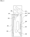
FIG. 2 is a cross-sectional view taken along line A-A inFIG. 1 ; and -
FIG. 3 is a view for illustrating an operation of a terminal housing for a motor according to one embodiment of the present invention. - Since the present invention may be modified in various ways and may have various embodiments, specific embodiments are illustrated in the drawings and are described in detail in the present specification.
- The terms "first," "second," etc. may be used to describe various components, but the components are not limited by such terms. The terms are used only for the purpose of distinguishing one component from other components. For example, a first component may be designated as a second component without departing from the scope of the present invention. In the same manner, the second component may be designated as the first component. The term "and/or" encompasses both combinations of the plurality of related items disclosed and any item from among the plurality of related items disclosed.
- When an arbitrary component is described as "being connected to" or "being linked to" another component, this should be understood to mean that still another component(s) may exist between them, although the arbitrary component may be directly connected to, or linked to, the second component. In contrast, when an arbitrary component is described as "being directly connected to" or "being directly linked to" another component, this should be understood to mean that no intervening component exists between them.
- The terms used in the specification of the present application are used for only illustrating specific embodiments, and are not intended to limit the present invention. A singular expression can include a plural expression as long as it does not have an apparently different meaning in context. In the present specification, the terms "include" and "have" should be understood to be intended to designate that illustrated features, numbers, steps, operations, components, parts, or combinations thereof exist and not to preclude the existence of one or more different features, numbers, steps, operations, components, parts, or combinations thereof, or the possibility of the addition thereof.
- Unless otherwise specified, all of the terms which are used herein, including the technical or scientific terms, have the same meanings as those that are generally understood by a person having ordinary knowledge in the art to which the present invention pertains. The terms defined in a generally used dictionary must be understood to have meanings identical to those used in the context of a related art, and are not to be construed to have ideal or excessively formal meanings unless they are obviously specified in the present specification.
- The embodiment of the present invention will be described in detail below with reference to the accompanying drawings. The structural element which is the same as or corresponds to the structural element which is already illustrated is indicated by the same reference numeral, and an illustration thereon is omitted.
-
FIG. 1 is a perspective view showing a stator of a motor employing a terminal housing for a motor according to one embodiment of the present invention. - Referring to
FIG. 1 , astator 100 of a motor employing a terminal housing for a motor according to one embodiment of the present invention includes astator core 110, a plurality ofteeth 120, aninsulator 130, acoil 140, and aterminal housing 300 for a motor. - The
stator core 110 is formed by stacking a plurality of cylindrical silicon steel plates and forms a magnetic circuit through which a magnetic field passes. - The plurality of
teeth 120 are spaced apart from each other at a regular interval and protrude in the inward direction of thestator core 110. - Meanwhile, the plurality of
teeth 120 may be formed of the same material as the material employed for forming thestator core 110. The plurality ofteeth 120 may be formed integrally with thestator core 110. In other words, by stacking donut-shaped silicon steel plates, each of which having protrusions protruding inward and spaced from each other at a regular interval, the protrusions become the plurality ofteeth 120 and the donut-shaped parts can become thestator core 110. In addition, the plurality ofteeth 120 and thestator core 110 can be separately formed to enable the teeth to be inserted in the groove provided at an inner side of thestator core 110. - The
insulator 130 is formed of an insulating material such as plastic and the like, and fitted to theteeth 120. Thisinsulator 130 insulates the plurality ofteeth 120 and thecoil 140 wound around each of the plurality ofteeth 120. - One end of a
terminal 200 is connected to thecoil 140, and the other end of the terminal is received in theterminal housing 300 for the motor. An external power is supplied to thecoil 140 via theterminal 200 to enable the plurality ofteeth 120 to form a magnetic field. - The
terminal housing 300 for the motor includes a terminal housingmain body 301 in which theterminal 200 is received. - If another terminal housing is inserted in the terminal housing
main body 301, theterminal housing 300 for the motor constructed as above allows theterminal 200 received therein to be electrically connected to a terminal received in another terminal housing. In addition, theterminal housing 300 for the motor protects the terminals which are electrically connected to each other, against an external force or a waterlogging. - Below, the
terminal housing 300 for the motor according to the present invention and theterminal 200 are described in more detail with reference to the drawings. -
FIG. 2 is a cross-sectional view taken along line A-A inFIG.1 . - Referring to
FIG. 2 , theterminal housing 200 includes acoil connecting part 210 to which thecoil 140 is connected, a terminal insertingpart 220 into which another terminal is inserted, and a connectingpart 230 connecting thecoil connecting part 210 and the terminal insertingpart 220. Here, the connectingpart 230 is inserted into a terminal insertinghole 302 of theterminal housing 300 for the motor, which will be described later. - The
terminal housing 300 for the motor includes the terminal housingmain body 301, achamber 310 formed in the terminal housingmain body 301 and serving as a space into which another terminal housing is inserted and in which theterminal inserting part 220 of theterminal 200 is placed, and the terminal insertinghole 302 formed in the terminal housingmain body 301 in the shape of a hole. Here, theterminal connecting part 230 is inserted into the terminal insertinghole 302. - The terms of "upward," "downward," "right," "left," "forward," and "backward" mentioned below indicate the direction or the place determined on the basis of
FIG. 2 . - A
curved portion 321 is provided on a side of thechamber 310 around the terminal insertinghole 302 to enable theterminal connecting part 230 to be moved in the right and left directions. Due to thecurved portion 320, theterminal 200 can be moved in the right and left directions or the forward and backward directions in a state where theterminal 200 is inserted into the terminal insertinghole 302. - A
deviation preventing wall 320 is formed on a left inner wall of thechamber 310 for preventing a deviation of theterminal 200 from thechamber 310, which is caused by an excessive movement of theterminal 200 in the left direction. Here, thedeviation preventing wall 320 may be formed by extending the left inner wall. - A
movement restriction part 330 is formed on a right inner wall of thechamber 310 for enabling theterminal 200 to be moved a certain distance in the right direction. Themovement restriction part 330 restricts an excessive movement of theterminal 200 in the right direction. Here, themovement restriction part 330 may be formed in a rib shape. - A downward
movement restriction part 340 is formed on a lower portion of the right inner wall of thechamber 310 for enabling theterminal 200 to be moved a certain distance in the downward direction. This downwardmovement restriction part 340 restricts an excessive downward movement of a lower end of the terminal 200. Here, the downwardmovement restriction part 340 may be formed in a protrusion shape extending from the right inner wall of thechamber 310 to an inside of thechamber 310. - Below, an operation of the terminal housing for the motor according to one embodiment of the present invention is described with reference to the drawings.
-
FIG. 3 is a view for illustrating an operation of a terminal housing for a motor according to one embodiment of the present invention. - Referring to
FIG. 3 , when another terminal is inserted into theterminal housing 300 of the motor, if the other terminal is not accurately inserted into theterminal inserting part 220, the terminal 200 is moved in the left direction d1 or the right direction d2 by thecurved portion 320. Due to the above, a force which is rapidly and excessively exerted to the terminal 200 is alleviated so that a damage of the terminal 200 and theterminal housing 300 for the motor is prevented. - By the present invention as described above, when another terminal housing is coupled to the terminal housing for the motor, it is possible to prevent the terminals assembled to these terminal housings from being damaged.
Claims (1)
- A motor using a terminal housing (300) for a motor; comprising,a stator (100);a terminal (200) having a coil connecting part (210) to which a coil (140) of the stator is connected, terminal inserting part (220) into which another terminal is inserted, and a terminal connecting part (230) connecting the coil connecting part (210) and the terminal inserting part (220),a terminal housing (300) for the motor includes a terminal housing main body (301) in which the terminal (200) is received;the terminal housing main body (301) having a terminal inserting hole (302) formed therein, which the terminal connecting part (230) is inserted into and providing a chamber for receiving the terminal inserting part (220); andcharacterized in that the terminal inserting part (220) comprises a right branch and a left branch extending from the connecting part inside the chamber;the terminal housing (300) further comprising a curved portion (321) provided on a side of the chamber around the inserting hole (302), the curved portion being curved to enable the terminal to be moved in the right and left directions;a deviation preventing wall (320) formed on a left inner wall of the chamber (310) wherein. when the terminal is in a far left position, the left branch of the terminal inserting part (220) contacts the deviation preventing wall (320) such that a movement of the left branch of the terminal inserting part (220) is blocked to the left against the deviation preventing wall (320);a movement restriction part (330) formed on a right inner wall of the chamber (310) wherein, when the terminal is in a far right position, the right branch of the terminal inserting part (220) contacts the movement restriction part (330), the movement restriction part being formed in a rib shape, such that a movement of the right branch of the terminal inserting part (220) is blocked to the right against the movement restriction part (330); and;a downward movement restriction part (340) formed on a lower portion of the right inner wall of the chamber (310) wherein, when the terminal is in the far right position, the right branch of the terminal inserting part (220) contacts the downward movement restriction part (340), the downward movement restriction part (340) being formed in a protrusion shape extending from the right inner wall of the chamber (310) to an inside of the chamber (310), such that the movement of the right branch of the terminal inserting part (220) is blocked downward against the downward movement restriction part (340).
Applications Claiming Priority (1)
| Application Number | Priority Date | Filing Date | Title |
|---|---|---|---|
| KR1020120126304A KR101975362B1 (en) | 2012-11-08 | 2012-11-08 | Terminal housing for motor and Motor having the same of |
Publications (3)
| Publication Number | Publication Date |
|---|---|
| EP2731237A2 EP2731237A2 (en) | 2014-05-14 |
| EP2731237A3 EP2731237A3 (en) | 2018-02-14 |
| EP2731237B1 true EP2731237B1 (en) | 2024-07-03 |
Family
ID=49546342
Family Applications (1)
| Application Number | Title | Priority Date | Filing Date |
|---|---|---|---|
| EP13192057.1A Active EP2731237B1 (en) | 2012-11-08 | 2013-11-08 | Terminal housing for motor and motor employing the same |
Country Status (4)
| Country | Link |
|---|---|
| US (1) | US9479023B2 (en) |
| EP (1) | EP2731237B1 (en) |
| KR (1) | KR101975362B1 (en) |
| CN (1) | CN103811921B (en) |
Families Citing this family (4)
| Publication number | Priority date | Publication date | Assignee | Title |
|---|---|---|---|---|
| JP2016208783A (en) * | 2015-04-28 | 2016-12-08 | 日本電産サンキョー株式会社 | motor |
| US10411541B2 (en) * | 2016-04-20 | 2019-09-10 | Hyundai Motor Company | Driving motor for environmentally friendly vehicles |
| CN107039792A (en) * | 2016-12-14 | 2017-08-11 | 上海艾铭思汽车控制系统有限公司 | A kind of motor inserted sheet and electric system |
| KR20210123916A (en) | 2020-04-06 | 2021-10-14 | 엘지이노텍 주식회사 | Motor |
Family Cites Families (8)
| Publication number | Priority date | Publication date | Assignee | Title |
|---|---|---|---|---|
| US3012159A (en) * | 1959-08-31 | 1961-12-05 | Gen Electric | Terminal arrangement for electrical apparatus |
| DE29920231U1 (en) * | 1999-11-17 | 2001-04-05 | Weidmüller Interface GmbH & Co, 32760 Detmold | Screwless terminal |
| JP3971987B2 (en) * | 2002-06-13 | 2007-09-05 | 日本電産サンキョー株式会社 | Motor stator structure |
| KR100543096B1 (en) * | 2003-11-28 | 2006-01-20 | 삼성광주전자 주식회사 | motor |
| JP4594026B2 (en) * | 2004-10-07 | 2010-12-08 | 多摩川精機株式会社 | Resolver external conductor fixing structure |
| JP4429246B2 (en) | 2005-09-30 | 2010-03-10 | ヒロセ電機株式会社 | Electrical connector for flat cable |
| DE102007022806B3 (en) * | 2007-05-11 | 2008-11-27 | Wago Verwaltungsgesellschaft Mbh | clamping member |
| KR101848922B1 (en) | 2011-09-21 | 2018-04-13 | 엘지이노텍 주식회사 | Terminal connection structure for Motor |
-
2012
- 2012-11-08 KR KR1020120126304A patent/KR101975362B1/en not_active Expired - Fee Related
-
2013
- 2013-11-07 US US13/998,512 patent/US9479023B2/en active Active
- 2013-11-08 CN CN201310553039.1A patent/CN103811921B/en active Active
- 2013-11-08 EP EP13192057.1A patent/EP2731237B1/en active Active
Also Published As
| Publication number | Publication date |
|---|---|
| CN103811921A (en) | 2014-05-21 |
| CN103811921B (en) | 2017-09-26 |
| US20140125169A1 (en) | 2014-05-08 |
| KR20140059925A (en) | 2014-05-19 |
| US9479023B2 (en) | 2016-10-25 |
| EP2731237A3 (en) | 2018-02-14 |
| EP2731237A2 (en) | 2014-05-14 |
| KR101975362B1 (en) | 2019-05-07 |
Similar Documents
| Publication | Publication Date | Title |
|---|---|---|
| US9847591B2 (en) | Electric terminal assembly | |
| EP2908385B1 (en) | Charging inlet device | |
| US9450319B2 (en) | Cable connector and connector device having the same | |
| EP2448386B1 (en) | Power-supply cord arrangement structure | |
| US8845351B2 (en) | Connector housing with alignment guidance feature | |
| EP2621019A1 (en) | Coaxial connector | |
| EP2731237B1 (en) | Terminal housing for motor and motor employing the same | |
| EP2892114B1 (en) | Motor terminal assembly and method of assembling a motor using the same | |
| US9142906B2 (en) | Power plug capable of simple assembly | |
| EP3188315B1 (en) | Cable connector | |
| CN104241859B (en) | Coil for antenna equipment | |
| KR101674581B1 (en) | Housing, bobbin, and electronic device | |
| EP3072748A1 (en) | Protector, assembly of wire with protector, and assembling method therefor | |
| JP2016058386A (en) | Submersible electric connector with rail mount | |
| CN104145375A (en) | Electrical connector with a push-in type contact | |
| US20130210279A1 (en) | Wire line connector | |
| US7604518B2 (en) | Electrical contact with retention latch | |
| EP2445058A1 (en) | Electric connector assembly | |
| WO2014136010A1 (en) | Connection terminal and connector assembly | |
| US20150311763A1 (en) | Two-component isolation of bl stators | |
| EP3001443A1 (en) | Winding module for electromagnetic switching device | |
| CN110168675B (en) | Thermal protector | |
| WO2014114323A1 (en) | Electrical high power connection assembly | |
| EP2736121A1 (en) | Antenna device | |
| KR102353541B1 (en) | A Magnetic Type of a Charging Connector |
Legal Events
| Date | Code | Title | Description |
|---|---|---|---|
| PUAI | Public reference made under article 153(3) epc to a published international application that has entered the european phase |
Free format text: ORIGINAL CODE: 0009012 |
|
| 17P | Request for examination filed |
Effective date: 20140331 |
|
| AK | Designated contracting states |
Kind code of ref document: A2 Designated state(s): AL AT BE BG CH CY CZ DE DK EE ES FI FR GB GR HR HU IE IS IT LI LT LU LV MC MK MT NL NO PL PT RO RS SE SI SK SM TR |
|
| AX | Request for extension of the european patent |
Extension state: BA ME |
|
| RAP1 | Party data changed (applicant data changed or rights of an application transferred) |
Owner name: LG INNOTEK CO., LTD. |
|
| RAP1 | Party data changed (applicant data changed or rights of an application transferred) |
Owner name: LG INNOTEK CO., LTD. |
|
| PUAL | Search report despatched |
Free format text: ORIGINAL CODE: 0009013 |
|
| AK | Designated contracting states |
Kind code of ref document: A3 Designated state(s): AL AT BE BG CH CY CZ DE DK EE ES FI FR GB GR HR HU IE IS IT LI LT LU LV MC MK MT NL NO PL PT RO RS SE SI SK SM TR |
|
| AX | Request for extension of the european patent |
Extension state: BA ME |
|
| RIC1 | Information provided on ipc code assigned before grant |
Ipc: H02K 5/22 20060101AFI20180108BHEP |
|
| STAA | Information on the status of an ep patent application or granted ep patent |
Free format text: STATUS: EXAMINATION IS IN PROGRESS |
|
| 17Q | First examination report despatched |
Effective date: 20181105 |
|
| GRAP | Despatch of communication of intention to grant a patent |
Free format text: ORIGINAL CODE: EPIDOSNIGR1 |
|
| STAA | Information on the status of an ep patent application or granted ep patent |
Free format text: STATUS: GRANT OF PATENT IS INTENDED |
|
| INTG | Intention to grant announced |
Effective date: 20240220 |
|
| GRAS | Grant fee paid |
Free format text: ORIGINAL CODE: EPIDOSNIGR3 |
|
| GRAA | (expected) grant |
Free format text: ORIGINAL CODE: 0009210 |
|
| STAA | Information on the status of an ep patent application or granted ep patent |
Free format text: STATUS: THE PATENT HAS BEEN GRANTED |
|
| AK | Designated contracting states |
Kind code of ref document: B1 Designated state(s): AL AT BE BG CH CY CZ DE DK EE ES FI FR GB GR HR HU IE IS IT LI LT LU LV MC MK MT NL NO PL PT RO RS SE SI SK SM TR |
|
| RAP3 | Party data changed (applicant data changed or rights of an application transferred) |
Owner name: LG INNOTEK CO., LTD. |
|
| REG | Reference to a national code |
Ref country code: CH Ref legal event code: EP |
|
| REG | Reference to a national code |
Ref country code: DE Ref legal event code: R096 Ref document number: 602013085849 Country of ref document: DE |
|
| REG | Reference to a national code |
Ref country code: LT Ref legal event code: MG9D |
|
| REG | Reference to a national code |
Ref country code: NL Ref legal event code: MP Effective date: 20240703 |
|
| PG25 | Lapsed in a contracting state [announced via postgrant information from national office to epo] |
Ref country code: PT Free format text: LAPSE BECAUSE OF FAILURE TO SUBMIT A TRANSLATION OF THE DESCRIPTION OR TO PAY THE FEE WITHIN THE PRESCRIBED TIME-LIMIT Effective date: 20241104 |
|
| REG | Reference to a national code |
Ref country code: AT Ref legal event code: MK05 Ref document number: 1700854 Country of ref document: AT Kind code of ref document: T Effective date: 20240703 |
|
| PG25 | Lapsed in a contracting state [announced via postgrant information from national office to epo] |
Ref country code: NL Free format text: LAPSE BECAUSE OF FAILURE TO SUBMIT A TRANSLATION OF THE DESCRIPTION OR TO PAY THE FEE WITHIN THE PRESCRIBED TIME-LIMIT Effective date: 20240703 |
|
| PG25 | Lapsed in a contracting state [announced via postgrant information from national office to epo] |
Ref country code: PT Free format text: LAPSE BECAUSE OF FAILURE TO SUBMIT A TRANSLATION OF THE DESCRIPTION OR TO PAY THE FEE WITHIN THE PRESCRIBED TIME-LIMIT Effective date: 20241104 Ref country code: NL Free format text: LAPSE BECAUSE OF FAILURE TO SUBMIT A TRANSLATION OF THE DESCRIPTION OR TO PAY THE FEE WITHIN THE PRESCRIBED TIME-LIMIT Effective date: 20240703 |
|
| PGFP | Annual fee paid to national office [announced via postgrant information from national office to epo] |
Ref country code: DE Payment date: 20241021 Year of fee payment: 12 |
|
| PG25 | Lapsed in a contracting state [announced via postgrant information from national office to epo] |
Ref country code: NO Free format text: LAPSE BECAUSE OF FAILURE TO SUBMIT A TRANSLATION OF THE DESCRIPTION OR TO PAY THE FEE WITHIN THE PRESCRIBED TIME-LIMIT Effective date: 20241003 |
|
| PG25 | Lapsed in a contracting state [announced via postgrant information from national office to epo] |
Ref country code: GR Free format text: LAPSE BECAUSE OF FAILURE TO SUBMIT A TRANSLATION OF THE DESCRIPTION OR TO PAY THE FEE WITHIN THE PRESCRIBED TIME-LIMIT Effective date: 20241004 Ref country code: FI Free format text: LAPSE BECAUSE OF FAILURE TO SUBMIT A TRANSLATION OF THE DESCRIPTION OR TO PAY THE FEE WITHIN THE PRESCRIBED TIME-LIMIT Effective date: 20240703 Ref country code: PL Free format text: LAPSE BECAUSE OF FAILURE TO SUBMIT A TRANSLATION OF THE DESCRIPTION OR TO PAY THE FEE WITHIN THE PRESCRIBED TIME-LIMIT Effective date: 20240703 |
|
| PG25 | Lapsed in a contracting state [announced via postgrant information from national office to epo] |
Ref country code: BG Free format text: LAPSE BECAUSE OF FAILURE TO SUBMIT A TRANSLATION OF THE DESCRIPTION OR TO PAY THE FEE WITHIN THE PRESCRIBED TIME-LIMIT Effective date: 20240703 |
|
| PG25 | Lapsed in a contracting state [announced via postgrant information from national office to epo] |
Ref country code: LV Free format text: LAPSE BECAUSE OF FAILURE TO SUBMIT A TRANSLATION OF THE DESCRIPTION OR TO PAY THE FEE WITHIN THE PRESCRIBED TIME-LIMIT Effective date: 20240703 |
|
| PG25 | Lapsed in a contracting state [announced via postgrant information from national office to epo] |
Ref country code: AT Free format text: LAPSE BECAUSE OF FAILURE TO SUBMIT A TRANSLATION OF THE DESCRIPTION OR TO PAY THE FEE WITHIN THE PRESCRIBED TIME-LIMIT Effective date: 20240703 Ref country code: IS Free format text: LAPSE BECAUSE OF FAILURE TO SUBMIT A TRANSLATION OF THE DESCRIPTION OR TO PAY THE FEE WITHIN THE PRESCRIBED TIME-LIMIT Effective date: 20241103 |
|
| PG25 | Lapsed in a contracting state [announced via postgrant information from national office to epo] |
Ref country code: CZ Free format text: LAPSE BECAUSE OF FAILURE TO SUBMIT A TRANSLATION OF THE DESCRIPTION OR TO PAY THE FEE WITHIN THE PRESCRIBED TIME-LIMIT Effective date: 20240703 Ref country code: HR Free format text: LAPSE BECAUSE OF FAILURE TO SUBMIT A TRANSLATION OF THE DESCRIPTION OR TO PAY THE FEE WITHIN THE PRESCRIBED TIME-LIMIT Effective date: 20240703 |
|
| PG25 | Lapsed in a contracting state [announced via postgrant information from national office to epo] |
Ref country code: ES Free format text: LAPSE BECAUSE OF FAILURE TO SUBMIT A TRANSLATION OF THE DESCRIPTION OR TO PAY THE FEE WITHIN THE PRESCRIBED TIME-LIMIT Effective date: 20240703 Ref country code: RS Free format text: LAPSE BECAUSE OF FAILURE TO SUBMIT A TRANSLATION OF THE DESCRIPTION OR TO PAY THE FEE WITHIN THE PRESCRIBED TIME-LIMIT Effective date: 20241003 |
|
| PG25 | Lapsed in a contracting state [announced via postgrant information from national office to epo] |
Ref country code: RS Free format text: LAPSE BECAUSE OF FAILURE TO SUBMIT A TRANSLATION OF THE DESCRIPTION OR TO PAY THE FEE WITHIN THE PRESCRIBED TIME-LIMIT Effective date: 20241003 Ref country code: PL Free format text: LAPSE BECAUSE OF FAILURE TO SUBMIT A TRANSLATION OF THE DESCRIPTION OR TO PAY THE FEE WITHIN THE PRESCRIBED TIME-LIMIT Effective date: 20240703 Ref country code: NO Free format text: LAPSE BECAUSE OF FAILURE TO SUBMIT A TRANSLATION OF THE DESCRIPTION OR TO PAY THE FEE WITHIN THE PRESCRIBED TIME-LIMIT Effective date: 20241003 Ref country code: LV Free format text: LAPSE BECAUSE OF FAILURE TO SUBMIT A TRANSLATION OF THE DESCRIPTION OR TO PAY THE FEE WITHIN THE PRESCRIBED TIME-LIMIT Effective date: 20240703 Ref country code: IS Free format text: LAPSE BECAUSE OF FAILURE TO SUBMIT A TRANSLATION OF THE DESCRIPTION OR TO PAY THE FEE WITHIN THE PRESCRIBED TIME-LIMIT Effective date: 20241103 Ref country code: HR Free format text: LAPSE BECAUSE OF FAILURE TO SUBMIT A TRANSLATION OF THE DESCRIPTION OR TO PAY THE FEE WITHIN THE PRESCRIBED TIME-LIMIT Effective date: 20240703 Ref country code: GR Free format text: LAPSE BECAUSE OF FAILURE TO SUBMIT A TRANSLATION OF THE DESCRIPTION OR TO PAY THE FEE WITHIN THE PRESCRIBED TIME-LIMIT Effective date: 20241004 Ref country code: FI Free format text: LAPSE BECAUSE OF FAILURE TO SUBMIT A TRANSLATION OF THE DESCRIPTION OR TO PAY THE FEE WITHIN THE PRESCRIBED TIME-LIMIT Effective date: 20240703 Ref country code: ES Free format text: LAPSE BECAUSE OF FAILURE TO SUBMIT A TRANSLATION OF THE DESCRIPTION OR TO PAY THE FEE WITHIN THE PRESCRIBED TIME-LIMIT Effective date: 20240703 Ref country code: CZ Free format text: LAPSE BECAUSE OF FAILURE TO SUBMIT A TRANSLATION OF THE DESCRIPTION OR TO PAY THE FEE WITHIN THE PRESCRIBED TIME-LIMIT Effective date: 20240703 Ref country code: BG Free format text: LAPSE BECAUSE OF FAILURE TO SUBMIT A TRANSLATION OF THE DESCRIPTION OR TO PAY THE FEE WITHIN THE PRESCRIBED TIME-LIMIT Effective date: 20240703 Ref country code: AT Free format text: LAPSE BECAUSE OF FAILURE TO SUBMIT A TRANSLATION OF THE DESCRIPTION OR TO PAY THE FEE WITHIN THE PRESCRIBED TIME-LIMIT Effective date: 20240703 |
|
| REG | Reference to a national code |
Ref country code: DE Ref legal event code: R097 Ref document number: 602013085849 Country of ref document: DE |
|
| PG25 | Lapsed in a contracting state [announced via postgrant information from national office to epo] |
Ref country code: RO Free format text: LAPSE BECAUSE OF FAILURE TO SUBMIT A TRANSLATION OF THE DESCRIPTION OR TO PAY THE FEE WITHIN THE PRESCRIBED TIME-LIMIT Effective date: 20240703 Ref country code: DK Free format text: LAPSE BECAUSE OF FAILURE TO SUBMIT A TRANSLATION OF THE DESCRIPTION OR TO PAY THE FEE WITHIN THE PRESCRIBED TIME-LIMIT Effective date: 20240703 Ref country code: SM Free format text: LAPSE BECAUSE OF FAILURE TO SUBMIT A TRANSLATION OF THE DESCRIPTION OR TO PAY THE FEE WITHIN THE PRESCRIBED TIME-LIMIT Effective date: 20240703 |
|
| PG25 | Lapsed in a contracting state [announced via postgrant information from national office to epo] |
Ref country code: EE Free format text: LAPSE BECAUSE OF FAILURE TO SUBMIT A TRANSLATION OF THE DESCRIPTION OR TO PAY THE FEE WITHIN THE PRESCRIBED TIME-LIMIT Effective date: 20240703 |
|
| PG25 | Lapsed in a contracting state [announced via postgrant information from national office to epo] |
Ref country code: SK Free format text: LAPSE BECAUSE OF FAILURE TO SUBMIT A TRANSLATION OF THE DESCRIPTION OR TO PAY THE FEE WITHIN THE PRESCRIBED TIME-LIMIT Effective date: 20240703 Ref country code: IT Free format text: LAPSE BECAUSE OF FAILURE TO SUBMIT A TRANSLATION OF THE DESCRIPTION OR TO PAY THE FEE WITHIN THE PRESCRIBED TIME-LIMIT Effective date: 20240703 |
|
| PLBE | No opposition filed within time limit |
Free format text: ORIGINAL CODE: 0009261 |
|
| STAA | Information on the status of an ep patent application or granted ep patent |
Free format text: STATUS: NO OPPOSITION FILED WITHIN TIME LIMIT |
|
| 26N | No opposition filed |
Effective date: 20250404 |
|
| REG | Reference to a national code |
Ref country code: CH Ref legal event code: PL |
|
| PG25 | Lapsed in a contracting state [announced via postgrant information from national office to epo] |
Ref country code: MC Free format text: LAPSE BECAUSE OF FAILURE TO SUBMIT A TRANSLATION OF THE DESCRIPTION OR TO PAY THE FEE WITHIN THE PRESCRIBED TIME-LIMIT Effective date: 20240703 |
|
| PG25 | Lapsed in a contracting state [announced via postgrant information from national office to epo] |
Ref country code: LU Free format text: LAPSE BECAUSE OF NON-PAYMENT OF DUE FEES Effective date: 20241108 |
|
| REG | Reference to a national code |
Ref country code: CH Ref legal event code: PL |
|
| GBPC | Gb: european patent ceased through non-payment of renewal fee |
Effective date: 20241108 |
|
| PG25 | Lapsed in a contracting state [announced via postgrant information from national office to epo] |
Ref country code: CH Free format text: LAPSE BECAUSE OF NON-PAYMENT OF DUE FEES Effective date: 20241130 |
|
| REG | Reference to a national code |
Ref country code: BE Ref legal event code: MM Effective date: 20241130 |
|
| PG25 | Lapsed in a contracting state [announced via postgrant information from national office to epo] |
Ref country code: SE Free format text: LAPSE BECAUSE OF FAILURE TO SUBMIT A TRANSLATION OF THE DESCRIPTION OR TO PAY THE FEE WITHIN THE PRESCRIBED TIME-LIMIT Effective date: 20240703 |
|
| PG25 | Lapsed in a contracting state [announced via postgrant information from national office to epo] |
Ref country code: GB Free format text: LAPSE BECAUSE OF NON-PAYMENT OF DUE FEES Effective date: 20241108 Ref country code: BE Free format text: LAPSE BECAUSE OF NON-PAYMENT OF DUE FEES Effective date: 20241130 |
|
| PG25 | Lapsed in a contracting state [announced via postgrant information from national office to epo] |
Ref country code: FR Free format text: LAPSE BECAUSE OF NON-PAYMENT OF DUE FEES Effective date: 20241130 |
|
| PG25 | Lapsed in a contracting state [announced via postgrant information from national office to epo] |
Ref country code: IE Free format text: LAPSE BECAUSE OF NON-PAYMENT OF DUE FEES Effective date: 20241108 |
|
| PG25 | Lapsed in a contracting state [announced via postgrant information from national office to epo] |
Ref country code: HU Free format text: LAPSE BECAUSE OF FAILURE TO SUBMIT A TRANSLATION OF THE DESCRIPTION OR TO PAY THE FEE WITHIN THE PRESCRIBED TIME-LIMIT; INVALID AB INITIO Effective date: 20131108 |
|
| PG25 | Lapsed in a contracting state [announced via postgrant information from national office to epo] |
Ref country code: CY Free format text: LAPSE BECAUSE OF FAILURE TO SUBMIT A TRANSLATION OF THE DESCRIPTION OR TO PAY THE FEE WITHIN THE PRESCRIBED TIME-LIMIT; INVALID AB INITIO Effective date: 20131108 |