EP2730846A2 - Fuel injector - Google Patents
Fuel injector Download PDFInfo
- Publication number
- EP2730846A2 EP2730846A2 EP13191948.2A EP13191948A EP2730846A2 EP 2730846 A2 EP2730846 A2 EP 2730846A2 EP 13191948 A EP13191948 A EP 13191948A EP 2730846 A2 EP2730846 A2 EP 2730846A2
- Authority
- EP
- European Patent Office
- Prior art keywords
- flow
- fuel injector
- delta wing
- injector according
- combustor
- Prior art date
- Legal status (The legal status is an assumption and is not a legal conclusion. Google has not performed a legal analysis and makes no representation as to the accuracy of the status listed.)
- Withdrawn
Links
- 239000000446 fuel Substances 0.000 title claims abstract description 73
- 238000011144 upstream manufacturing Methods 0.000 claims abstract description 17
- 239000012530 fluid Substances 0.000 claims abstract description 15
- 230000007704 transition Effects 0.000 claims description 15
- 238000002485 combustion reaction Methods 0.000 claims description 10
- 238000002347 injection Methods 0.000 description 15
- 239000007924 injection Substances 0.000 description 15
- 239000000463 material Substances 0.000 description 8
- PUAQLLVFLMYYJJ-UHFFFAOYSA-N 2-aminopropiophenone Chemical compound CC(N)C(=O)C1=CC=CC=C1 PUAQLLVFLMYYJJ-UHFFFAOYSA-N 0.000 description 6
- 230000037361 pathway Effects 0.000 description 6
- 239000000203 mixture Substances 0.000 description 2
- 230000002093 peripheral effect Effects 0.000 description 2
- 238000010248 power generation Methods 0.000 description 2
- 230000004075 alteration Effects 0.000 description 1
- 230000001419 dependent effect Effects 0.000 description 1
- 239000003344 environmental pollutant Substances 0.000 description 1
- 238000010438 heat treatment Methods 0.000 description 1
- 230000007246 mechanism Effects 0.000 description 1
- 230000035515 penetration Effects 0.000 description 1
- 231100000719 pollutant Toxicity 0.000 description 1
- 238000006467 substitution reaction Methods 0.000 description 1
Images

Classifications
-
- F—MECHANICAL ENGINEERING; LIGHTING; HEATING; WEAPONS; BLASTING
- F02—COMBUSTION ENGINES; HOT-GAS OR COMBUSTION-PRODUCT ENGINE PLANTS
- F02C—GAS-TURBINE PLANTS; AIR INTAKES FOR JET-PROPULSION PLANTS; CONTROLLING FUEL SUPPLY IN AIR-BREATHING JET-PROPULSION PLANTS
- F02C7/00—Features, components parts, details or accessories, not provided for in, or of interest apart form groups F02C1/00 - F02C6/00; Air intakes for jet-propulsion plants
- F02C7/22—Fuel supply systems
-
- F—MECHANICAL ENGINEERING; LIGHTING; HEATING; WEAPONS; BLASTING
- F23—COMBUSTION APPARATUS; COMBUSTION PROCESSES
- F23R—GENERATING COMBUSTION PRODUCTS OF HIGH PRESSURE OR HIGH VELOCITY, e.g. GAS-TURBINE COMBUSTION CHAMBERS
- F23R3/00—Continuous combustion chambers using liquid or gaseous fuel
- F23R3/28—Continuous combustion chambers using liquid or gaseous fuel characterised by the fuel supply
-
- F—MECHANICAL ENGINEERING; LIGHTING; HEATING; WEAPONS; BLASTING
- F23—COMBUSTION APPARATUS; COMBUSTION PROCESSES
- F23R—GENERATING COMBUSTION PRODUCTS OF HIGH PRESSURE OR HIGH VELOCITY, e.g. GAS-TURBINE COMBUSTION CHAMBERS
- F23R3/00—Continuous combustion chambers using liquid or gaseous fuel
- F23R3/28—Continuous combustion chambers using liquid or gaseous fuel characterised by the fuel supply
- F23R3/34—Feeding into different combustion zones
Definitions
- the subject matter disclosed herein relates to enhancements to fuel injectors and, more particularly, to a delta wing enhancement for fuel injectors.
- a typical gas turbine engine includes a compressor that compresses inlet air, a combustor in which the compressed inlet air and fuel are combusted to produce a main flow of products of the combustion, a turbine and a transition piece.
- the turbine is receptive of the main flow and configured to expand the main flow in power generation operations.
- the transition piece is fluidly interposed between the combustor and the turbine.
- Combustible materials such as the compressed inlet air and fuel are injectable into a head end of the combustor.
- additional combustible materials are injectable into downstream sections of the combustor and the transition piece.
- a performance of the gas turbine engine is largely dependent upon the ability of the combustible materials to be mixed prior to combustion. That is, as a degree of mixing of the combustible materials increases, increasingly completed combustion operations can be achieved. This in turn leads to a greater power output from the turbine and a decrease in the amount of pollutant emissions produced by the gas turbine engine.
- a fuel injector includes a surface disposed proximate to a flow of a first fluid and a delta wing feature.
- the surface has upstream and downstream portions defined relative to the flow and defines an injector hole in the downstream portion by which a jet of a second fluid is injectable into the flow.
- the delta wing feature is disposed on the surface at the upstream portion and is configured to lift an oncoming portion of the flow off the surface and to cause the oncoming portion of the flow to form a pair of counter-rotating vortices that respectively co-rotate with the jet in a cross-flow direction.
- a fuel injector includes a surface formed as a tubular element and disposed proximate to a flow of a first fluid, the surface having upstream and downstream portions defined relative to the flow and defining injector holes in the downstream portion by which jets of a second fluid are injectable into the flow and delta wing features.
- the delta wing features are disposed on the surface at the upstream portion and each one of the delta wing features is associated with a corresponding one of the injector holes and is configured to lift an oncoming portion of the flow off the surface and to cause the oncoming portion of the flow to form a pair of counter-rotating vortices that respectively co-rotate with the corresponding one of the jets in a cross-flow direction.
- a fuel injector includes a surface formed as a toroidal element and disposed proximate to a flow of a first fluid, the surface having upstream and downstream portions defined relative to the flow and defining injector holes in the downstream portion by which jets of a second fluid are injectable into the flow and delta wing features.
- the delta wing features are disposed on the surface at the upstream portion and each one of the delta wing features is associated with a corresponding one of the injector holes and is configured to lift an oncoming portion of the flow off the surface and to cause the oncoming portion of the flow to form a pair of counter-rotating vortices that respectively co-rotate with the corresponding one of the jets in a cross-flow direction.
- the description provided below relates to a delta wing feature added upstream from a jet in cross flow, which is formed by a fuel delivery hole on an outer style late lean injection (LLI) injector.
- the delta wing is positioned to point downstream toward the fuel hole and has an increasing thickness toward its downstream end.
- the delta wing thus provides a ramp for the oncoming air flow to be lifted off the injector wall.
- the shape of the wing sets up a counter-rotating vortex pair that co-rotates with the fuel jet in a cross-flow direction. This enhances vorticity, which is a primary fuel/air mixing mechanism, and fuel jet penetration, which is a key factor in mixing and avoiding flame holding concerns.
- the geometry of the delta wing is such that very small wakes exist behind the wing that could present a flame holding risk.
- the delta wing feature is applicable in the LLI injector, as noted above, and in additional applications as well. Such additional applications include quaternary fuel injection and fuel nozzle fuel injection. In each case, the delta wing feature may be incorporated into peg-shaped or annular fuel injectors.
- a gas turbine engine 1 includes a compressor 2 that compresses inlet air, a combustor 3 in which the compressed inlet air and fuel are provided as combustible materials and combusted to produce a main flow of products of the combustion, a turbine 4 and a transition piece 5.
- the turbine 4 is receptive of the main flow and configured to expand the main flow in power generation operations.
- the transition piece 5 is fluidly interposed between the combustor 3 and the turbine 4.
- the combustor 3 includes an annular combustor liner 6 and the transition piece 5 includes an annular transition piece liner 7.
- the combustor liner 6 and the transition piece liner 7 are cooperatively formed to define an interior 8 through which the main flow proceeds from the combustor 3 to the turbine 4.
- Combustible materials such as the compressed inlet air and fuel are injectable into the interior 8 at the head end 9 of the combustor 3 via fuel nozzles 10.
- additional combustible materials are injectable into the interior 8 at downstream sections 11 of the combustor 3 via first stage fuel injectors 12 and at upstream sections 13 of the transition piece 5 via second stage fuel injectors 14.
- the combustor liner 6 is surrounded by an annular flow sleeve 15 that is coupled to an end plate 16.
- the combustor liner 6 and the flow sleeve 15 cooperatively define an annulus 17 through which the compressed air output from the compressor 2 flows toward the head end 9 before turning radially inwardly and then flowing in the opposite direction toward the fuel nozzles 10.
- a quat fuel injector 18 may be disposed within the annulus 17 such that quaternary fuel can be injected into the flow of the compressed air.
- the quat fuel injector 18 may be annular or toroidal (see FIG. 3 ) or tubular or peg-shaped (see FIG. 4 ). In the former case, quaternary fuel injection is generally directed radially out of the quat fuel injector 18 whereas in the latter case, the quaternary fuel injection is generally directed circumferentially out of the quat fuel injector 18.
- each of the fuel nozzles 10 includes a center body 19 and a peripheral wall 20.
- the center body 19 has a longitudinal axis that is oriented to extend along the axial dimension of the combustor 3.
- the peripheral wall 20 surrounds the center body 19 along the longitudinal axis to define an annular pre-mixing pathway 21 along which compressed air flows toward a combustion zone defined in the interior 8 of the combustor 3.
- a fuel nozzle injector 22 may be disposed within the annular pre-mixing pathway 21 such that fuel can be injected into the flow of the compressed air.
- the fuel nozzle injector 22 may be annular or toroidal (see FIG. 5 ) or tubular or peg-shaped (see FIG. 6 ). In the former case, the fuel injection is generally directed radially out of the fuel nozzle injector 22 whereas in the latter case, the fuel injection is generally directed circumferentially out of the fuel nozzle injector 22.
- a fuel injector 30 is provided and may be employed as one or more of the first or second stage fuel injectors 12 and 14 (see FIG. 2 ).
- the fuel injector 30 includes a surface 31 disposed proximate to a flow 32 of a first fluid and a delta wing feature 33.
- the surface 31 has an upstream portion 34 and a downstream portion 35, which are defined relative to a predominant direction of the flow 32.
- the surface 31 is further formed to define an injector hole 36 in the downstream portion 35.
- a second fluid is injectable into the flow 32 via the injector hole 36 whereby the injector hole 36 generates a jet 37 of the second fluid.
- the delta wing feature 33 is disposed on the surface 31 at the upstream portion 34 such that an alignment of the injector hole 36 and the delta wing feature 33 is provided substantially in parallel with a predominant direction of the flow 32.
- the delta wing feature 33 includes a ramp portion 38 and a wing portion 39.
- the ramp portion 38 is configured to lift an oncoming portion 40 of the flow 32 off the surface 31 and has a curved leading edge 41 and a substantially flat, ramped surface 42.
- the wing portion 39 is configured to cause the portion 40 of the flow 32 to form a pair of counter-rotating vortices 43 that respectively co-rotate with the jet 37 in a cross-flow direction.
- the wing portion 39 includes converging lateral surfaces 44 that form a substantially linear trailing edge 45.
- the curved leading edge 41 and the substantially linear trailing edge 45 may be transversely oriented with respect to one another.
- delta wing feature 33, the injector hole 36, and the jet 37 may each be plural in number.
- each one of the jets 37 is generated by a corresponding one of the injector holes 36 and each one of the delta wing features 33 is associated with a corresponding one of the injector holes 36.
- the fuel injector 30 may be provided for use as one or more of the first stage fuel injectors 12 or the second stage fuel injectors 14 for axially staged injection or LLI.
- the flow 32 is provided as a mixture (e.g., a micro-mixture) of low or high heating value fuel and compressed air that is drawn from a compressor discharge casing (CDC) disposed around the downstream sections 11 of the combustor 3 and the upstream sections 13 of the transition piece 5.
- CDC compressor discharge casing
- the flow 32 is thus directed radially inwardly toward the main flow proceeding from the combustor 3, through a transition zone defined in the transition piece 5 and toward the turbine 4.
- the surface 31 forms a tubular element 50 that has a longitudinal axis 51.
- the surface 31 faces inwardly with the injection holes 36 and the delta wing features 33 correspondingly arranged annularly whereby the jets 37 are aimed toward a common central target.
- the tubular element 50 may be disposed with the longitudinal axis 51 arranged along a radial orientation relative to the main flow (see FIG. 2 ).
- the fuel injector 30 may be provided as the quat fuel injector 18 (see FIG. 3 ) or the fuel nozzle injector 22 (see FIG. 5 ).
- the flow 32 is provided as the flow of compressed air proceeding through the annulus 17 toward the head end 9 of the combustor 3.
- the flow 32 is provided as the flow of compressed air proceeding through the annular pathway 21 toward the combustion zone defined in the interior 8 of the combustor 3.
- the surface 31 forms a toroidal element 60 having a poloidal axis 61 and has inward and outward sides that face radially inwardly and radially outwardly, respectively, relative to an axial dimension of the combustor 3.
- the toroidal element 60 is disposable in the annulus 17 or the annular pre-mixing pathway 21 with the poloidal axis 61 arranged substantially in parallel with the axial dimension of the combustor 3.
- the injection holes 36 and the delta wing features 33 may be correspondingly arranged along the annular length of the surface 31 to face radially inwardly or outwardly whereby the jets 37 may be similarly aimed radially inwardly or outwardly.
- the fuel injector 30 may be provided as the quat fuel injector 18 (see FIG. 4 ) or the fuel nozzle injector 22 (see FIG. 6 ).
- the flow 32 is provided as the flow of compressed air proceeding through the annulus 17 toward the head end 9 of the combustor 3.
- the flow 32 is provided as the flow of compressed air proceeding through the annular pathway 21 toward the combustion zone defined in the interior 8 of the combustor 3.
- the surface 31 forms a tubular element 70 having a longitudinal axis 71 and has lateral sides that face in the circumferential direction relative to an axial dimension of the combustor 3.
- the tubular element 70 is disposable in the annulus 17 or the annular pre-mixing pathway 21 with the longitudinal axis 71 arranged substantially perpendicularly with respect to the axial dimension of the combustor 3.
- the injection holes 36 and the delta wing features 33 may be correspondingly arranged along the longitudinal length of the surface 31 to face circumferentially whereby the jets 37 may be similarly aimed circumferentially.
Landscapes
- Engineering & Computer Science (AREA)
- Chemical & Material Sciences (AREA)
- Combustion & Propulsion (AREA)
- Mechanical Engineering (AREA)
- General Engineering & Computer Science (AREA)
- Pressure-Spray And Ultrasonic-Wave- Spray Burners (AREA)
Abstract
A fuel injector is provided and includes a surface (31) disposed proximate to a flow (32) of a first fluid and a delta wing feature (33). The surface (31) has upstream and downstream portions defined relative to the flow (32) and defines an injector hole (36) in the downstream portion by which a jet (37) of a second fluid is injectable into the flow (32). The delta wing feature (33) is disposed on the surface (31) at the upstream portion and is configured to lift an oncoming portion (40) of the flow (32) off the surface (31) and to cause the oncoming portion (40) of the flow (32) to form a pair of counter-rotating vortices (43) that respectively co-rotate with the jet (37) in a crossflow direction.
Description
- The subject matter disclosed herein relates to enhancements to fuel injectors and, more particularly, to a delta wing enhancement for fuel injectors.
- A typical gas turbine engine includes a compressor that compresses inlet air, a combustor in which the compressed inlet air and fuel are combusted to produce a main flow of products of the combustion, a turbine and a transition piece. The turbine is receptive of the main flow and configured to expand the main flow in power generation operations. The transition piece is fluidly interposed between the combustor and the turbine. Combustible materials, such as the compressed inlet air and fuel are injectable into a head end of the combustor. In the case of axially staged injection or late lean injection (LLI), additional combustible materials are injectable into downstream sections of the combustor and the transition piece.
- Whether the combustible materials are injected into the head end of the combustor, the downstream sections of the combustor or the transition piece, a performance of the gas turbine engine is largely dependent upon the ability of the combustible materials to be mixed prior to combustion. That is, as a degree of mixing of the combustible materials increases, increasingly completed combustion operations can be achieved. This in turn leads to a greater power output from the turbine and a decrease in the amount of pollutant emissions produced by the gas turbine engine.
- According to one aspect of the invention, a fuel injector is provided and includes a surface disposed proximate to a flow of a first fluid and a delta wing feature. The surface has upstream and downstream portions defined relative to the flow and defines an injector hole in the downstream portion by which a jet of a second fluid is injectable into the flow. The delta wing feature is disposed on the surface at the upstream portion and is configured to lift an oncoming portion of the flow off the surface and to cause the oncoming portion of the flow to form a pair of counter-rotating vortices that respectively co-rotate with the jet in a cross-flow direction.
- According to another aspect of the invention, a fuel injector is provided and includes a surface formed as a tubular element and disposed proximate to a flow of a first fluid, the surface having upstream and downstream portions defined relative to the flow and defining injector holes in the downstream portion by which jets of a second fluid are injectable into the flow and delta wing features. The delta wing features are disposed on the surface at the upstream portion and each one of the delta wing features is associated with a corresponding one of the injector holes and is configured to lift an oncoming portion of the flow off the surface and to cause the oncoming portion of the flow to form a pair of counter-rotating vortices that respectively co-rotate with the corresponding one of the jets in a cross-flow direction.
- According to yet another aspect of the invention, a fuel injector is provided and includes a surface formed as a toroidal element and disposed proximate to a flow of a first fluid, the surface having upstream and downstream portions defined relative to the flow and defining injector holes in the downstream portion by which jets of a second fluid are injectable into the flow and delta wing features. The delta wing features are disposed on the surface at the upstream portion and each one of the delta wing features is associated with a corresponding one of the injector holes and is configured to lift an oncoming portion of the flow off the surface and to cause the oncoming portion of the flow to form a pair of counter-rotating vortices that respectively co-rotate with the corresponding one of the jets in a cross-flow direction.
- These and other advantages and features will become more apparent from the following description taken in conjunction with the drawings.
- The subject matter, which is regarded as the invention, is particularly pointed out and distinctly claimed in the claims at the conclusion of the specification. The foregoing and other features, and advantages of the invention are apparent from the following detailed description taken in conjunction with the accompanying drawings in which:
-
FIG. 1 is a schematic illustration of a turbomachine; -
FIG. 2 is an enlarged schematic illustration of a combustor and a transition piece of a turbomachine; -
FIG. 3 is an enlarged schematic illustration of a combustor head end of a turbomachine in accordance with embodiments; -
FIG. 4 is an enlarged schematic illustration of a combustor head end of a turbomachine in accordance with alternative embodiments; -
FIG. 5 is an enlarged schematic illustration of fuel nozzle of a turbomachine in accordance with embodiments; -
FIG. 6 is an enlarged schematic illustration of fuel nozzle of a turbomachine in accordance with alternative embodiments; -
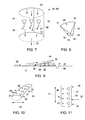
FIG. 7 is a cutaway perspective view of a fuel injector having delta wing features; -
FIG. 8 is a perspective view of a single delta wing feature; -
FIG. 9 is a side view of a single delta wing feature; -
FIG. 10 is a partial perspective view of a toroidal fuel injector in accordance with embodiments; and -
FIG. 11 is a partial perspective view of a longitudinal fuel injector in accordance with embodiments. - The detailed description explains embodiments of the invention, together with advantages and features, by way of example with reference to the drawings.
- The description provided below relates to a delta wing feature added upstream from a jet in cross flow, which is formed by a fuel delivery hole on an outer style late lean injection (LLI) injector. The delta wing is positioned to point downstream toward the fuel hole and has an increasing thickness toward its downstream end. The delta wing thus provides a ramp for the oncoming air flow to be lifted off the injector wall. Additionally, the shape of the wing sets up a counter-rotating vortex pair that co-rotates with the fuel jet in a cross-flow direction. This enhances vorticity, which is a primary fuel/air mixing mechanism, and fuel jet penetration, which is a key factor in mixing and avoiding flame holding concerns. Finally, the geometry of the delta wing is such that very small wakes exist behind the wing that could present a flame holding risk.
- The delta wing feature is applicable in the LLI injector, as noted above, and in additional applications as well. Such additional applications include quaternary fuel injection and fuel nozzle fuel injection. In each case, the delta wing feature may be incorporated into peg-shaped or annular fuel injectors.
- With reference to
FIGS. 1 and 2 , agas turbine engine 1 includes acompressor 2 that compresses inlet air, acombustor 3 in which the compressed inlet air and fuel are provided as combustible materials and combusted to produce a main flow of products of the combustion, aturbine 4 and atransition piece 5. Theturbine 4 is receptive of the main flow and configured to expand the main flow in power generation operations. Thetransition piece 5 is fluidly interposed between thecombustor 3 and theturbine 4. Thecombustor 3 includes anannular combustor liner 6 and thetransition piece 5 includes an annulartransition piece liner 7. Thecombustor liner 6 and thetransition piece liner 7 are cooperatively formed to define aninterior 8 through which the main flow proceeds from thecombustor 3 to theturbine 4. - Combustible materials, such as the compressed inlet air and fuel are injectable into the
interior 8 at thehead end 9 of thecombustor 3 viafuel nozzles 10. In the case of axially staged injection or late lean injection (LLI), additional combustible materials are injectable into theinterior 8 atdownstream sections 11 of thecombustor 3 via firststage fuel injectors 12 and atupstream sections 13 of thetransition piece 5 via secondstage fuel injectors 14. - With reference to
FIGS. 3 and 4 , thecombustor liner 6 is surrounded by anannular flow sleeve 15 that is coupled to anend plate 16. Thecombustor liner 6 and theflow sleeve 15 cooperatively define anannulus 17 through which the compressed air output from thecompressor 2 flows toward thehead end 9 before turning radially inwardly and then flowing in the opposite direction toward thefuel nozzles 10. In some embodiments and, as shown inFIGS. 3 and 4 , aquat fuel injector 18 may be disposed within theannulus 17 such that quaternary fuel can be injected into the flow of the compressed air. Thequat fuel injector 18 may be annular or toroidal (seeFIG. 3 ) or tubular or peg-shaped (seeFIG. 4 ). In the former case, quaternary fuel injection is generally directed radially out of thequat fuel injector 18 whereas in the latter case, the quaternary fuel injection is generally directed circumferentially out of thequat fuel injector 18. - With reference to
FIGS. 5 and 6 , each of thefuel nozzles 10 includes acenter body 19 and aperipheral wall 20. Thecenter body 19 has a longitudinal axis that is oriented to extend along the axial dimension of thecombustor 3. Theperipheral wall 20 surrounds thecenter body 19 along the longitudinal axis to define an annularpre-mixing pathway 21 along which compressed air flows toward a combustion zone defined in theinterior 8 of thecombustor 3. As shown inFIGS. 5 and 6 , afuel nozzle injector 22 may be disposed within the annular pre-mixingpathway 21 such that fuel can be injected into the flow of the compressed air. Thefuel nozzle injector 22 may be annular or toroidal (seeFIG. 5 ) or tubular or peg-shaped (seeFIG. 6 ). In the former case, the fuel injection is generally directed radially out of thefuel nozzle injector 22 whereas in the latter case, the fuel injection is generally directed circumferentially out of thefuel nozzle injector 22. - With reference to
FIGS. 7-9 , afuel injector 30 is provided and may be employed as one or more of the first or secondstage fuel injectors 12 and 14 (seeFIG. 2 ). Thefuel injector 30 includes asurface 31 disposed proximate to aflow 32 of a first fluid and adelta wing feature 33. Thesurface 31 has anupstream portion 34 and adownstream portion 35, which are defined relative to a predominant direction of theflow 32. Thesurface 31 is further formed to define aninjector hole 36 in thedownstream portion 35. A second fluid is injectable into theflow 32 via theinjector hole 36 whereby theinjector hole 36 generates ajet 37 of the second fluid. - The
delta wing feature 33 is disposed on thesurface 31 at theupstream portion 34 such that an alignment of theinjector hole 36 and thedelta wing feature 33 is provided substantially in parallel with a predominant direction of theflow 32. Thedelta wing feature 33 includes aramp portion 38 and awing portion 39. Theramp portion 38 is configured to lift an oncomingportion 40 of theflow 32 off thesurface 31 and has a curvedleading edge 41 and a substantially flat, rampedsurface 42. Thewing portion 39 is configured to cause theportion 40 of theflow 32 to form a pair ofcounter-rotating vortices 43 that respectively co-rotate with thejet 37 in a cross-flow direction. Thewing portion 39 includes converginglateral surfaces 44 that form a substantially linear trailingedge 45. The curvedleading edge 41 and the substantially linear trailingedge 45 may be transversely oriented with respect to one another. - In accordance with embodiments, it will be understood that
delta wing feature 33, theinjector hole 36, and thejet 37 may each be plural in number. In such cases, as shown inFIG. 7 , each one of thejets 37 is generated by a corresponding one of the injector holes 36 and each one of the delta wing features 33 is associated with a corresponding one of the injector holes 36. - In accordance with embodiments and, with reference to
FIGS. 2 and7-9 , thefuel injector 30 may be provided for use as one or more of the firststage fuel injectors 12 or the secondstage fuel injectors 14 for axially staged injection or LLI. In such cases, theflow 32 is provided as a mixture (e.g., a micro-mixture) of low or high heating value fuel and compressed air that is drawn from a compressor discharge casing (CDC) disposed around thedownstream sections 11 of thecombustor 3 and theupstream sections 13 of thetransition piece 5. Theflow 32 is thus directed radially inwardly toward the main flow proceeding from thecombustor 3, through a transition zone defined in thetransition piece 5 and toward theturbine 4. - In order to contain the
flow 32, thesurface 31 forms a tubular element 50 that has alongitudinal axis 51. Thesurface 31 faces inwardly with the injection holes 36 and the delta wing features 33 correspondingly arranged annularly whereby thejets 37 are aimed toward a common central target. Further, in order to direct theflow 32 radially into the main flow, the tubular element 50 may be disposed with thelongitudinal axis 51 arranged along a radial orientation relative to the main flow (seeFIG. 2 ). - In accordance with further alternative embodiments and, with reference to
FIGS. 3, 5 ,7 and 10 , thefuel injector 30 may be provided as the quat fuel injector 18 (seeFIG. 3 ) or the fuel nozzle injector 22 (seeFIG. 5 ). In the former case, theflow 32 is provided as the flow of compressed air proceeding through theannulus 17 toward thehead end 9 of thecombustor 3. In the latter case, theflow 32 is provided as the flow of compressed air proceeding through theannular pathway 21 toward the combustion zone defined in theinterior 8 of thecombustor 3. In either case, thesurface 31 forms atoroidal element 60 having apoloidal axis 61 and has inward and outward sides that face radially inwardly and radially outwardly, respectively, relative to an axial dimension of thecombustor 3. Thetoroidal element 60 is disposable in theannulus 17 or theannular pre-mixing pathway 21 with thepoloidal axis 61 arranged substantially in parallel with the axial dimension of thecombustor 3. Thus, the injection holes 36 and the delta wing features 33 may be correspondingly arranged along the annular length of thesurface 31 to face radially inwardly or outwardly whereby thejets 37 may be similarly aimed radially inwardly or outwardly. - In accordance with further alternative embodiments and, with reference to
FIGS. 4, 6 ,7 and 10 , thefuel injector 30 may be provided as the quat fuel injector 18 (seeFIG. 4 ) or the fuel nozzle injector 22 (seeFIG. 6 ). In the former case, theflow 32 is provided as the flow of compressed air proceeding through theannulus 17 toward thehead end 9 of thecombustor 3. In the latter case, theflow 32 is provided as the flow of compressed air proceeding through theannular pathway 21 toward the combustion zone defined in theinterior 8 of thecombustor 3. In either case, thesurface 31 forms atubular element 70 having alongitudinal axis 71 and has lateral sides that face in the circumferential direction relative to an axial dimension of thecombustor 3. Thetubular element 70 is disposable in theannulus 17 or theannular pre-mixing pathway 21 with thelongitudinal axis 71 arranged substantially perpendicularly with respect to the axial dimension of thecombustor 3. The injection holes 36 and the delta wing features 33 may be correspondingly arranged along the longitudinal length of thesurface 31 to face circumferentially whereby thejets 37 may be similarly aimed circumferentially. - While the invention has been described in detail in connection with only a limited number of embodiments, it should be readily understood that the invention is not limited to such disclosed embodiments. Rather, the invention can be modified to incorporate any number of variations, alterations, substitutions or equivalent arrangements not heretofore described, but which are commensurate with the spirit and scope of the invention. Additionally, while various embodiments of the invention have been described, it is to be understood that aspects of the invention may include only some of the described embodiments. Accordingly, the invention is not to be seen as limited by the foregoing description, but is only limited by the scope of the appended claims.
- Various aspects and embodiments of the present invention are defined by the following numbered clauses:
- 1. A fuel injector, comprising:
- a surface formed as a tubular element and disposed proximate to a flow of a first fluid,
- the surface having upstream and downstream portions defined relative to the flow and defining injector holes in the downstream portion by which jets of a second fluid are injectable into the flow; and
- delta wing features disposed on the surface at the upstream portion, each one of the delta wing features being associated with a corresponding one of the injector holes and being configured to lift an oncoming portion of the flow off the surface and to cause the oncoming portion of the flow to form a pair of counter-rotating vortices that respectively co-rotate with the corresponding one of the jets in a cross-flow direction.
- 2. The fuel injector according to
clause 1, wherein the surface faces inwardly and the injector holes, the jets and the delta wing features are arranged annularly. - 3. The fuel injector according to
clause
Claims (13)
- A fuel injector (30), comprising:a surface (31) disposed proximate to a flow (32) of a first fluid,the surface having upstream (34) and downstream (35) portions defined relative to the flow (32) and defining an injector hole (36) in the downstream portion (35) by which a jet (37) of a second fluid is injectable into the flow (32); anda delta wing feature (33) disposed on the surface (31) at the upstream portion (34), the delta wing feature (33) being configured to lift an oncoming portion (40) of the flow (32) off the surface (31) and to cause the oncoming portion (40) of the flow (32) to form a pair of counter-rotating vortices (43) that respectively co-rotate with the jet (37) in a cross-flow direction.
- The fuel injector according to claim 1, wherein the delta wing feature (33) comprises a curved leading edge (41).
- The fuel injector according to claim 1 or 2, wherein the delta wing feature (33) comprises a substantially flat, ramped surface (42).
- The fuel injector according to any of claims 1 to 3, wherein the delta wing feature (33) comprises converging lateral surfaces (44).
- The fuel injector according to any of claims 1 to 4, wherein the delta wing feature (33) comprises a substantially linear trailing edge (45).
- The fuel injector according to any of claims 1 to 5, wherein leading (43) and trailing (45) edges of the delta wing feature (33) are transversely oriented.
- The fuel injector according to any preceding claim, wherein an alignment of the injector hole (36) and the delta wing feature (33) is substantially parallel with a predominant direction of the flow (32).
- The fuel injector according to any preceding claim, wherein the injector hole (36) and the delta wing feature (33) are each plural in number, each one of the plural delta wing features (33) being associated with a corresponding one of the plural injector holes (36).
- The fuel injector according to any preceding claim, wherein the flow (32) is directed toward a main flow of products of combustion proceeding from a combustor (3), through a transition zone and toward a turbine (4).
- The fuel injector according to claim 9, wherein the surface forms a tubular element (50) having a longitudinal axis, the tubular element (50) being disposable with the longitudinal axis (51) arranged along a radial orientation relative to the main flow of the products of combustion.
- The fuel injector according to any preceding claim, wherein the flow (32) is directed toward one of a head end (9) of a combustor (3) or a combustion zone of a combustor (3).
- The fuel injector according to claim 11, wherein the surface forms a toroidal element (60) having a poloidal axis (61), the toroidal element (60) being disposable with the poloidal axis (61) arranged along an axial dimension of the combustor (3).
- The fuel injector according to claim 11, wherein the surface forms a tubular element (70) having a longitudinal axis (71), the tubular element (70) being disposable with the longitudinal axis (71) arranged along a radial dimension of the combustor (3).
Applications Claiming Priority (1)
| Application Number | Priority Date | Filing Date | Title |
|---|---|---|---|
| US13/672,147 US20140123653A1 (en) | 2012-11-08 | 2012-11-08 | Enhancement for fuel injector |
Publications (1)
| Publication Number | Publication Date |
|---|---|
| EP2730846A2 true EP2730846A2 (en) | 2014-05-14 |
Family
ID=49518870
Family Applications (1)
| Application Number | Title | Priority Date | Filing Date |
|---|---|---|---|
| EP13191948.2A Withdrawn EP2730846A2 (en) | 2012-11-08 | 2013-11-07 | Fuel injector |
Country Status (4)
| Country | Link |
|---|---|
| US (1) | US20140123653A1 (en) |
| EP (1) | EP2730846A2 (en) |
| JP (1) | JP2014095546A (en) |
| CN (1) | CN203880749U (en) |
Families Citing this family (7)
| Publication number | Priority date | Publication date | Assignee | Title |
|---|---|---|---|---|
| US10054314B2 (en) | 2015-12-17 | 2018-08-21 | General Electric Company | Slotted injector for axial fuel staging |
| CN106014487A (en) * | 2016-06-12 | 2016-10-12 | 上海交通大学 | Jet impingement control structure with cross flow in confined space |
| CN118043593A (en) * | 2021-08-27 | 2024-05-14 | 西门子能源全球有限两合公司 | Burner component with vortex generator and burner with the burner component |
| CN117515591B (en) * | 2023-11-20 | 2025-11-11 | 南京航空航天大学 | Nozzle with small support plate |
| US20250362017A1 (en) * | 2024-05-22 | 2025-11-27 | General Electric Company | Turbine engine and combustor therefor |
| CN119042661B (en) * | 2024-07-23 | 2025-12-05 | 北京航空航天大学 | A hydrogen fuel burner with staggered multi-point radial injection |
| CN119755674B (en) * | 2024-12-17 | 2025-12-26 | 北京航空航天大学 | Swirl burner |
Family Cites Families (12)
| Publication number | Priority date | Publication date | Assignee | Title |
|---|---|---|---|---|
| EP0623786B1 (en) * | 1993-04-08 | 1997-05-21 | Asea Brown Boveri Ag | Combustion chamber |
| DE59401177D1 (en) * | 1993-04-08 | 1997-01-16 | Abb Management Ag | Mixing and flame stabilization device in a combustion chamber with premix combustion |
| EP0619134B1 (en) * | 1993-04-08 | 1996-12-18 | ABB Management AG | Mixing receptacle |
| CH687832A5 (en) * | 1993-04-08 | 1997-02-28 | Asea Brown Boveri | Fuel supply for combustion. |
| DE59401018D1 (en) * | 1993-04-08 | 1996-12-19 | Abb Management Ag | Mixing chamber |
| DE19510744A1 (en) * | 1995-03-24 | 1996-09-26 | Abb Management Ag | Combustion chamber with two-stage combustion |
| US20090077972A1 (en) * | 2007-09-21 | 2009-03-26 | General Electric Company | Toroidal ring manifold for secondary fuel nozzle of a dln gas turbine |
| US20090241547A1 (en) * | 2008-03-31 | 2009-10-01 | Andrew Luts | Gas turbine fuel injector for lower heating capacity fuels |
| US8438852B2 (en) * | 2010-04-06 | 2013-05-14 | General Electric Company | Annular ring-manifold quaternary fuel distributor |
| US8545215B2 (en) * | 2010-05-17 | 2013-10-01 | General Electric Company | Late lean injection injector |
| US8281596B1 (en) * | 2011-05-16 | 2012-10-09 | General Electric Company | Combustor assembly for a turbomachine |
| US8919125B2 (en) * | 2011-07-06 | 2014-12-30 | General Electric Company | Apparatus and systems relating to fuel injectors and fuel passages in gas turbine engines |
-
2012
- 2012-11-08 US US13/672,147 patent/US20140123653A1/en not_active Abandoned
-
2013
- 2013-11-01 JP JP2013227816A patent/JP2014095546A/en active Pending
- 2013-11-07 EP EP13191948.2A patent/EP2730846A2/en not_active Withdrawn
- 2013-11-08 CN CN201320704297.0U patent/CN203880749U/en not_active Expired - Fee Related
Non-Patent Citations (1)
| Title |
|---|
| None |
Also Published As
| Publication number | Publication date |
|---|---|
| JP2014095546A (en) | 2014-05-22 |
| CN203880749U (en) | 2014-10-15 |
| US20140123653A1 (en) | 2014-05-08 |
Similar Documents
| Publication | Publication Date | Title |
|---|---|---|
| EP2730846A2 (en) | Fuel injector | |
| CN101713549B (en) | System and method for air-fuel mixing in gas turbines | |
| US20150159877A1 (en) | Late lean injection manifold mixing system | |
| JP2014132214A (en) | Fuel injector for supplying fuel to combustor | |
| EP3376109B1 (en) | Dual-fuel fuel nozzle with liquid fuel tip | |
| US20160061452A1 (en) | Corrugated cyclone mixer assembly to facilitate reduced nox emissions and improve operability in a combustor system | |
| EP4206534B1 (en) | Turbine engine fuel premixer | |
| CN102818290A (en) | Fuel nozzle with swirling vanes | |
| CN102809156A (en) | Double swirl burner with Venturi tube premixing section | |
| CN105940264A (en) | Combustor | |
| US12025311B2 (en) | Micromix fuel injection air nozzles | |
| CN116624892A (en) | Burner fuel assembly | |
| EP3425281B1 (en) | Pilot nozzle with inline premixing | |
| EP3169938B1 (en) | Axially staged gas turbine combustor with interstage premixer | |
| EP3220049B1 (en) | Gas turbine combustor having liner cooling guide vanes | |
| KR20240147655A (en) | Enhanced trailing edge fuel injection to alleviate flame holding | |
| EP3586062B1 (en) | Combustion system with axially staged fuel injection | |
| CN116498995A (en) | Burner fuel assembly | |
| CN102777930A (en) | Bi-directional fuel injection method | |
| US20260009540A1 (en) | Fuel nozzle | |
| EP3246630A1 (en) | Single can vortex combustor | |
| US20250362018A1 (en) | Turbine engine having a fuel nozzle including a curvilinear structure | |
| EP4641089A1 (en) | Fuel injector for a turbine engine | |
| US20260098640A1 (en) | Turbine engine having a fuel nozzle |
Legal Events
| Date | Code | Title | Description |
|---|---|---|---|
| PUAI | Public reference made under article 153(3) epc to a published international application that has entered the european phase |
Free format text: ORIGINAL CODE: 0009012 |
|
| 17P | Request for examination filed |
Effective date: 20131107 |
|
| AK | Designated contracting states |
Kind code of ref document: A2 Designated state(s): AL AT BE BG CH CY CZ DE DK EE ES FI FR GB GR HR HU IE IS IT LI LT LU LV MC MK MT NL NO PL PT RO RS SE SI SK SM TR |
|
| AX | Request for extension of the european patent |
Extension state: BA ME |
|
| STAA | Information on the status of an ep patent application or granted ep patent |
Free format text: STATUS: THE APPLICATION IS DEEMED TO BE WITHDRAWN |
|
| 18D | Application deemed to be withdrawn |
Effective date: 20170601 |