EP2730793A2 - Cage for thrust roller bearing - Google Patents
Cage for thrust roller bearing Download PDFInfo
- Publication number
- EP2730793A2 EP2730793A2 EP13191324.6A EP13191324A EP2730793A2 EP 2730793 A2 EP2730793 A2 EP 2730793A2 EP 13191324 A EP13191324 A EP 13191324A EP 2730793 A2 EP2730793 A2 EP 2730793A2
- Authority
- EP
- European Patent Office
- Prior art keywords
- cage
- axial direction
- annular portion
- bent
- thrust
- Prior art date
- Legal status (The legal status is an assumption and is not a legal conclusion. Google has not performed a legal analysis and makes no representation as to the accuracy of the status listed.)
- Granted
Links
- 239000000463 material Substances 0.000 description 4
- 229910000831 Steel Inorganic materials 0.000 description 3
- 239000010959 steel Substances 0.000 description 3
- 238000005452 bending Methods 0.000 description 2
- 230000000717 retained effect Effects 0.000 description 2
- 229910000975 Carbon steel Inorganic materials 0.000 description 1
- 239000010960 cold rolled steel Substances 0.000 description 1
- 230000000694 effects Effects 0.000 description 1
- 238000001746 injection moulding Methods 0.000 description 1
- 239000011347 resin Substances 0.000 description 1
- 229920005989 resin Polymers 0.000 description 1
- 239000010935 stainless steel Substances 0.000 description 1
- 229910001220 stainless steel Inorganic materials 0.000 description 1
Images


Classifications
-
- F—MECHANICAL ENGINEERING; LIGHTING; HEATING; WEAPONS; BLASTING
- F16—ENGINEERING ELEMENTS AND UNITS; GENERAL MEASURES FOR PRODUCING AND MAINTAINING EFFECTIVE FUNCTIONING OF MACHINES OR INSTALLATIONS; THERMAL INSULATION IN GENERAL
- F16C—SHAFTS; FLEXIBLE SHAFTS; ELEMENTS OR CRANKSHAFT MECHANISMS; ROTARY BODIES OTHER THAN GEARING ELEMENTS; BEARINGS
- F16C33/00—Parts of bearings; Special methods for making bearings or parts thereof
- F16C33/30—Parts of ball or roller bearings
- F16C33/46—Cages for rollers or needles
- F16C33/467—Details of individual pockets, e.g. shape or roller retaining means
- F16C33/4676—Details of individual pockets, e.g. shape or roller retaining means of the stays separating adjacent cage pockets, e.g. guide means for the bearing-surface of the rollers
-
- F—MECHANICAL ENGINEERING; LIGHTING; HEATING; WEAPONS; BLASTING
- F16—ENGINEERING ELEMENTS AND UNITS; GENERAL MEASURES FOR PRODUCING AND MAINTAINING EFFECTIVE FUNCTIONING OF MACHINES OR INSTALLATIONS; THERMAL INSULATION IN GENERAL
- F16C—SHAFTS; FLEXIBLE SHAFTS; ELEMENTS OR CRANKSHAFT MECHANISMS; ROTARY BODIES OTHER THAN GEARING ELEMENTS; BEARINGS
- F16C19/00—Bearings with rolling contact, for exclusively rotary movement
- F16C19/22—Bearings with rolling contact, for exclusively rotary movement with bearing rollers essentially of the same size in one or more circular rows, e.g. needle bearings
- F16C19/30—Bearings with rolling contact, for exclusively rotary movement with bearing rollers essentially of the same size in one or more circular rows, e.g. needle bearings for axial load mainly
- F16C19/305—Bearings with rolling contact, for exclusively rotary movement with bearing rollers essentially of the same size in one or more circular rows, e.g. needle bearings for axial load mainly consisting of rollers held in a cage
-
- F—MECHANICAL ENGINEERING; LIGHTING; HEATING; WEAPONS; BLASTING
- F16—ENGINEERING ELEMENTS AND UNITS; GENERAL MEASURES FOR PRODUCING AND MAINTAINING EFFECTIVE FUNCTIONING OF MACHINES OR INSTALLATIONS; THERMAL INSULATION IN GENERAL
- F16C—SHAFTS; FLEXIBLE SHAFTS; ELEMENTS OR CRANKSHAFT MECHANISMS; ROTARY BODIES OTHER THAN GEARING ELEMENTS; BEARINGS
- F16C33/00—Parts of bearings; Special methods for making bearings or parts thereof
- F16C33/30—Parts of ball or roller bearings
- F16C33/46—Cages for rollers or needles
- F16C33/467—Details of individual pockets, e.g. shape or roller retaining means
- F16C33/4682—Details of individual pockets, e.g. shape or roller retaining means of the end walls, e.g. interaction with the end faces of the rollers
-
- F—MECHANICAL ENGINEERING; LIGHTING; HEATING; WEAPONS; BLASTING
- F16—ENGINEERING ELEMENTS AND UNITS; GENERAL MEASURES FOR PRODUCING AND MAINTAINING EFFECTIVE FUNCTIONING OF MACHINES OR INSTALLATIONS; THERMAL INSULATION IN GENERAL
- F16C—SHAFTS; FLEXIBLE SHAFTS; ELEMENTS OR CRANKSHAFT MECHANISMS; ROTARY BODIES OTHER THAN GEARING ELEMENTS; BEARINGS
- F16C33/00—Parts of bearings; Special methods for making bearings or parts thereof
- F16C33/30—Parts of ball or roller bearings
- F16C33/46—Cages for rollers or needles
- F16C33/54—Cages for rollers or needles made from wire, strips, or sheet metal
- F16C33/541—Details of individual pockets, e.g. shape or roller retaining means
-
- F—MECHANICAL ENGINEERING; LIGHTING; HEATING; WEAPONS; BLASTING
- F16—ENGINEERING ELEMENTS AND UNITS; GENERAL MEASURES FOR PRODUCING AND MAINTAINING EFFECTIVE FUNCTIONING OF MACHINES OR INSTALLATIONS; THERMAL INSULATION IN GENERAL
- F16C—SHAFTS; FLEXIBLE SHAFTS; ELEMENTS OR CRANKSHAFT MECHANISMS; ROTARY BODIES OTHER THAN GEARING ELEMENTS; BEARINGS
- F16C33/00—Parts of bearings; Special methods for making bearings or parts thereof
- F16C33/30—Parts of ball or roller bearings
- F16C33/46—Cages for rollers or needles
- F16C33/54—Cages for rollers or needles made from wire, strips, or sheet metal
- F16C33/542—Cages for rollers or needles made from wire, strips, or sheet metal made from sheet metal
- F16C33/543—Cages for rollers or needles made from wire, strips, or sheet metal made from sheet metal from a single part
- F16C33/546—Cages for rollers or needles made from wire, strips, or sheet metal made from sheet metal from a single part with a M- or W-shaped cross section
Definitions
- the invention relates to a cage for a thrust roller bearing.
- the thrust cage has a large-diameter annular portion, a small-diameter annular portion and a plurality of cage bars.
- the large-diameter annular portion and the small-diameter annular portion are concentric with each other, and are located on substantially the same plane.
- the cage bars connect the large-diameter annular portion and the small-diameter annular portion to each other.
- the cage bars are arranged at intervals in the circumferential direction of the small-diameter annular portion.
- Each of the cage bars is bent into a generally U-shape in the axial direction of the small-diameter annular portion, as viewed in a section taken along the radial direction of the thrust cage. Further, all the cage bars are bent toward the same side in the axial direction of the small-diameter annular portion. In the above-described conventional thrust cage, the cage bars are bent into a generally U-shape, so that the thrust cage has an enhanced roller retaining capability.
- the cage bars of the above-described thrust cage are bent into a generally U-shape in the axial direction, the radial load bearing capacity of the above-described thrust cage is lower than that of a thrust cage having cage bars that are not bent. Therefore, there has been a demand that local deformation of the thrust cage, which is caused by holding the thrust cage between an inner ring and an outer ring, should be further suppressed, and the stiffness of the thrust cage against a radial compressive load should be enhanced.
- One object of the invention is to provide a cage for a thrust roller bearing, configured such that local deformation of the cage, which is caused by holding the cage between an inner ring and an outer ring, is suppressed and the stiffness of the cage against a radial compressive load is enhanced, while the roller retaining capability of the cage is appropriately maintained.
- An aspect of the invention relates to a cage for a thrust roller bearing, including: a first annular portion; and a plurality of cage bars extended from the first annular portion in a radial direction of the first annular portion, and located at intervals in a circumferential direction of the first annular portion.
- the cage has pockets formed between the cage bars that are adjacent to each other in the circumferential direction, rollers being arranged in the pockets.
- the cage bar of at least one of the pockets, the cage bar being on one side of the at least one of the pockets in the circumferential direction has a bent portion that is bent toward one side in an axial direction such that an end face of the cage bar on the other side in the axial direction is recessed toward the one side in the axial direction.
- the cage bar of the at least one of the pockets has a bent portion that is bent toward the other side in the axial direction such that an end face of the cage bar on the one side in the axial direction is recessed toward the other side in the axial direction.
- FIG. 1 is a schematic sectional view illustrating a thrust cylindrical roller bearing according to a first embodiment of the invention, taken along the radial direction of the thrust cylindrical roller bearing.
- the thrust cylindrical roller bearing includes an outer ring 1, an inner ring 2, a plurality of cylindrical rollers 3 and a cage 5 for a thrust cylindrical roller bearing (hereinafter, simply referred to as "thrust cage”).
- the outer ring 1 has a disc shape, and has a flat raceway surface 11. Further, the outer ring 1 has a bent extended portion 12.
- the bent extended portion 12 is located at a radially outer end portion of the outer ring 1.
- the bent extended portion 12 has a shape formed by bending a radially outer end portion of the outer ring 1 toward one side in the axial direction and is then extended along the axial direction toward the one side in the axial direction.
- the inner ring 2 has a disc shape, and has a flat raceway surface 21.
- the raceway surface 21 of the inner ring 2 is opposed to the raceway surface 11 of the outer ring 1 in the axial direction.
- the inner ring 2 has a bent extended portion 22.
- the bent extended portion 22 is located at a radially inner end portion of the inner ring 2.
- the bent extended portion 22 has a shape formed by bending a radially inner end portion of the inner ring 2 toward the other side in the axial direction and is then extended along the axial direction toward the other side in the axial direction.
- the cylindrical rollers 3 are arranged at intervals in the circumferential direction, while being retained, by thrust cage 5, between the raceway surface 11 of the outer ring 1 and the raceway surface 21 of the inner ring 2.
- the thrust cage 5 is made of a steel material that can be press-formed, for example, a cold-rolled steel (SPCC), carbon steels for machine structural use (S45C), or a general purpose stainless steel, and is formed by press-forming.
- SPCC cold-rolled steel
- S45C carbon steels for machine structural use
- the thrust cage 5 is overlapped with both the bent extended portion 12 of the outer ring 1 and the bent extended portion 22 of the inner ring 2 in the radial direction, so that the thrust cage 5 is prevented from coming off the outer ring 1 and the inner ring 2 in the radial direction.
- FIG. 2 is a perspective view illustrating part of the thrust cage 5, as viewed from one side in the axial direction of the thrust cage 5.
- the thrust cage 5 has a large-diameter annular portion 51, which may function as a first annular portion, a small-diameter annular portion 52, which may function as a second annular portion, and a plurality of cage bars 53.
- the large-diameter annular portion 51 and the small-diameter annular portion 52 are flat, and are located on substantially the same plane.
- the large-diameter annular portion 51 and the small-diameter annular portion 52 are concentric with each other, and are located on substantially the same plane.
- the large-diameter annular portion 51 is located radially outward of the small-diameter annular portion 52.
- the cage bars 53 connect the large-diameter annular portion 51 with the small-diameter annular portion 52.
- the cage bars 53 are arranged at intervals in the circumferential direction of the small-diameter annular portion 52.
- the thrust cage 5 has 2N (N is a natural number) pockets 55.
- the pockets 55 are positioned between the cage bars 53 that are adjacent to each other in the circumferential direction.
- the cylindrical rollers 3 are arranged in the pockets 55.
- each of the cage bars 53 has substantially the same thickness at any positions in the radial direction.
- Each of the cage bars 53 is bent in the axial direction such that an end face of the cage bar 53 on one side in the axial direction has a generally isosceles trapezoid-shaped recessed portion, as viewed in a section taken along the radial direction.
- any two of the cage bars 53 that are adjacent to each other in the circumferential direction are bent toward opposite sides in the axial direction.
- the cage bars 53 that are bent toward one side in the axial direction and the cage bars 53 that are bent toward the other side in the axial direction are alternately arranged in the circumferential direction.
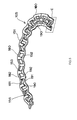
- FIG. 3 is a perspective view illustrating a cut section in the radial direction, indicated by a reference character B in FIG. 2 , and its surroundings, as viewed from the outside in the circumferential direction in FIG. 2 .
- each of the cage bars 53 has a large diameter-side connection portion 60 and a small diameter-side connection portion 61, in addition to a bent portion 62.
- the large diameter-side connection portion 60 is connected to the large-diameter annular portion 51, and is extended radially inward from a radially inner end face of the large-diameter annular portion 51.
- the small diameter-side connection portion 61 is connected to the small-diameter annular portion 52, and is extended radially outward from a radially outer end face of the small-diameter annular portion 52.
- the large diameter-side connection portion 60 and the small diameter-side connection portion 61 are both flat.
- the bent portion 62 is located at the center of each of the cage bars 53 in the radial direction. A radially outer end portion of the bent portion 62 is connected to a radially inner end portion of the large diameter-side connection portion 60. A radially inner end portion of the bent portion 62 is connected to a radially outer end portion of the small diameter-side connection portion 61.
- N (N is a natural number) cage bars 53 which are bent toward one side in the axial direction and which alternate with the cage bars 53 bent toward the other side in the axial direction, are overlapped with each other in the circumferential direction. Further, N (N is natural number) cage bars 53, which are bent toward the other side in the axial direction and which alternate with the cage bars 53 bent toward the one side in the axial direction, are also overlapped with each other in the circumferential direction.
- FIG. 4 is a perspective view illustrating a portion of the thrust cage 5 in FIG. 3 , around one pocket 55 of the thrust cage 5.
- the cage bar 53 on one side of the pocket 55 in the circumferential direction has a bent portion 62A that is bent toward the other side in the axial direction such that an end face 70 of the cage bar 53 on one side in the axial direction is recessed toward the other side in the axial direction.
- the cage bar 53 on the other side of the pocket 55 in the circumferential direction has a bent portion 62B that is bent toward the one side in the axial direction such that an end face 80 of the cage bar 53 on the other side in the axial direction is recessed toward the one side in the axial direction.
- the 2N bent portions 62 of the thrust cage 5 has N bent portions 62A and N bent portions 62B.
- the cage bar 53 on one side of the pocket 55 in the circumferential direction and the cage bar 53 on the other side of the pocket 55 in the circumferential direction are bent in the axial direction.
- the thrust cage 5 has at least two cage bars 53 that are bent toward the opposite sides in the axial direction, and the cage bars 53 that are bent toward one side in the axial direction and the cage bars 53 that are bent toward the other side in the axial direction are alternately arranged and located adjacent to each other in the circumferential direction.
- the mass balance of the thrust cage 5 in the axial direction is better than that in a conventional thrust cage in which all the cage bars are bent toward the same side in the axial direction. Therefore, as compared with the conventional thrust cage, the stiffness of the thrust cage 5 in each of the axial direction and the radial direction is enhanced, the stiffness of the thrust cage 5 against radial compressive loads as indicated by arrows AA' in FIG. 1 is enhanced, and local deformation of the thrust cage 5, which is caused by holding the thrust cage 5 between the outer ring 1 and the inner ring 2, is suppressed.
- each of the cage bars 53 has the bent portion 62 that is bent in the axial direction
- the bent portion 62 may have a lug that protrudes in the circumferential direction and that is used to prevent the cylindrical roller 3 from coming off.
- a subassembly formed of the thrust cage 5 and a plurality of the cylindrical rollers 3 is prepared. This makes it possible to facilitate, for example, the conveyance of the cylindrical roller bearing, and to reliably retain the cylindrical rollers 3 with the use of the thrust cage 5.
- the cage bar 53 on one side of the pocket 55 in the circumferential direction has the bent portion 62A that is bent toward the other side in the axial direction such that the end face 70 of the cage bar 53 on one side in the axial direction is recessed toward the other side in the axial direction.
- the cage bar 53 on the other side of the pocket 55 in the circumferential direction has the bent portion 62B that is bent toward the one side in the axial direction such that the end face 80 of the cage bar 53 on the other side in the axial direction is recessed toward the one side in the axial direction.
- the thrust cage according to the invention may be configured such that, at at least one of the pockets, the cage bar on one side of the pocket in the circumferential direction has the bent portion that is bent toward the other side in the axial direction such that the end face of the cage bar on one side in the axial direction is recessed toward the other side in the axial direction, and the cage bar on the other side of the pocket in the circumferential direction has the bent portion that is bent toward the one side in the axial direction such that the end face of the cage bar on the other side in the axial direction is recessed toward the one side in the axial direction.
- the thrust cage 5 has an even number of pockets 25.
- the thrust cage according to the invention may have an odd number of pockets. It is needless to say that, in the case where the thrust cage has an odd number of pockets, if all the cage bars have the bent portions, at at least one of the pockets, the two cage bars that define the pocket are bent toward the same side in the axial direction.
- the recessed portion formed in each of the cage bars 53 has an isosceles trapezoidal shape.
- the recessed portion formed in each of the cage bars may have a shape other than the isosceles trapezoidal shape, such as a substantially rectangular shape or a substantially semi-circular shape.
- the thrust cage 5 is made of a steel material.
- the thrust cage may be made of a resin material, and may be formed by, for example, injection molding.
- the rollers are cylindrical rollers (needle rollers or other cylindrical rollers) 3.
- the rollers may be tapered rollers or convex rollers (spherical rollers).
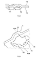
- FIG. 5 is a view corresponding to FIG. 2 and illustrating a thrust cage 105 according to a second embodiment of the invention.
- the thrust cage 105 in the second embodiment has an even number of pockets 155, like the thrust cage 5 in the first embodiment.
- the thrust cage 105 in the second embodiment differs from the thrust cage 5 in the first embodiment, in that a large-diameter annular portion 151 and a small-diameter annular portion 152 are both corrugated in a cycle of the same phase angle.
- descriptions on the same structures as those in the first embodiment, such as the structure that cage bars 153 have recessed portions will be omitted, and the advantageous effects as those in the first embodiment will also be omitted. Further, in the second embodiment, descriptions on the same modified examples as those in the first embodiments will also be omitted.
- the thrust cage 105 in the second embodiment is made of a steel material that is can be press-formed, and is formed by press-forming.
- the large-diameter annular portion 151 has such a shape that the large-diameter annular portion 151 extends in a zigzag manner, like a generally polygonal line, between a first axial position and a second axial position.
- the large-diameter annular portion 151 has 2M (M is a natural number) inter-cage bar portions 180 located between the cage bars 153 that are adjacent to each other in the circumferential direction.
- M inter-cage bar portions 180 that alternate with the other inter-cage bar portions 180 respectively have one axial side inclined portions 181 which are inclined toward one side in the axial direction, in a direction toward one side in the circumferential direction.
- the small-diameter annular portion 152 has such a shape that the small-diameter annular portion 152 extends in a zigzag manner, like a generally polygonal line, between a first axial position and a second axial position.
- the small-diameter annular portion 152 has 2M (M is a natural number) inter-cage bar portions 190 located between the cage bars 153 that are adjacent to each other in the circumferential direction.
- M inter-cage bar portions 190 that alternate with the other inter-cage bar portions 190 respectively have one axial side inclined portions 191 which are inclined toward the one side in the axial direction, in the direction toward the one side in the circumferential direction.
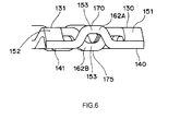
- FIG. 6 is a perspective view illustrating a cut section in the radial direction, indicated by a reference character C in FIG. 5 , and its surroundings, as viewed from the outside in the circumferential direction in FIG. 5 .
- the axial positions of portions 130, 131 of the large-diameter annular portion 151 and the small-diameter annular portion 152 substantially coincide with the axial position of a portion 170 of a bent portion 162A of the cage bar 153 extended from portions 140, 141 of the large-diameter annular portion 151 and the small-diameter annular portion 152.
- the portions 130, 131 are located on one side in the axial direction, and are located at positions farthest from the other side in the axial direction within the annular portions 151, 152.
- the portions 140, 141 are located on the other side in the axial direction, and are located at positions farthest from the one side in the axial direction within the annular portions 151, 152.
- the portion 170 is located on the one side in the axial direction, and is located at a position farthest from the other side in the axial direction within the bent portion 162A.
- the axial positions of the portions 140, 141 of the large-diameter annular portion 151 and the small-diameter annular portion 152 substantially coincide with the axial position of a portion 175 of a bent portion 162B of the cage bar 153 extended from the portions 130, 131 of the large-diameter annular portion 151 and the small-diameter annular portion 152.
- the portions 140, 141 are located on the other side in the axial direction, and are located at positions farthest from the one side in the axial direction within the annular portions 151, 152.
- the portions 130, 131 are located on the one side in the axial direction, and are located at positions farthest from the other side in the axial direction within the annular portions 151, 152.
- the portion 175 is located on the other side in the axial direction, and is located at a position farthest from the one side in the axial direction within the bent portion 162B.
- the large-diameter annular portion 151 has axially inclined portions 181, 182 that are alternately arranged in the circumferential direction and that are inclined toward the opposite sides in the axial direction.
- the small-diameter annular portion 152 has axially inclined portions 191, 192 that are alternately arranged in the circumferential direction and that are inclined toward the opposite sides in the axial direction.
- both the large-diameter annular portion 151 and the small-diameter annular portion 152 are corrugated in the axial direction.
- the cage bars 153 are provided with lugs that protrude in the circumferential direction and that are used to retain the rollers, more lugs can be located at different axial positions.
- the lugs for preventing the rollers from coming off the rollers can be retained in a more stable manner.
- the inter-cage bar portions 180, 190 of the annular portions 151, 152 are inclined toward the respective sides in the axial direction, in the direction toward the one side in the circumferential direction, over the entire region in the circumferential direction, where the inter-cage bar portions 180, 190 are provided.
- the inter-cage bar portions of at least one of the annular portions 151, 152 may be inclined toward the respective sides in the axial direction, in the direction toward the one side in the circumferential direction, over only part of the region in the circumferential direction, where the inter-cage bar portions are provided.
- the large-diameter annular portion 151 and the small-diameter annular portion 152 respectively have an even number of the inter-cage bar portions 180 and an even number of the inter-cage bar portions 190
- each of all the inter-cage bar portions 180 is the inclined portion 181 or the inclined portion 182
- each of all the inter-cage bar portions 190 is the inclined portion 191 or the inclined portion 192
- the large-diameter annular portion 151 and the small-diameter annular portion 152 are have corrugated shapes.
- each of the large-diameter annular portion and the small-diameter annular portion may have an odd number of the inter-cage bar portions.
- each of the large-diameter annular portion and the small-diameter annular portion may have an even number of the inter-cage bar portions.
- the large-diameter annular portion 151 and the small-diameter annular portion 152 are both corrugated like a generally polygonal line.
- the large-diameter annular portion and the small-diameter annular portion may be both corrugated such that the large-diameter annular portion and the small-diameter annular portion are curved.
- the cage for a thrust roller bearing configured such that local deformation of the cage, which is caused by holding the cage between the inner ring and the outer ring, is suppressed and the stiffness of the cage against a radial compressive load is enhanced, while the roller retaining capability of the cage is appropriately maintained.
Landscapes
- Engineering & Computer Science (AREA)
- General Engineering & Computer Science (AREA)
- Mechanical Engineering (AREA)
- Rolling Contact Bearings (AREA)
Abstract
Description
- The invention relates to a cage for a thrust roller bearing.
- A conventional cage for a thrust roller bearing (hereinafter, simply referred to as "thrust cage") is described in, for example, Japanese Patent Application Publication No.
2008-202797 JP 2008-202797 A - Each of the cage bars is bent into a generally U-shape in the axial direction of the small-diameter annular portion, as viewed in a section taken along the radial direction of the thrust cage. Further, all the cage bars are bent toward the same side in the axial direction of the small-diameter annular portion. In the above-described conventional thrust cage, the cage bars are bent into a generally U-shape, so that the thrust cage has an enhanced roller retaining capability.
- However, because the cage bars of the above-described thrust cage are bent into a generally U-shape in the axial direction, the radial load bearing capacity of the above-described thrust cage is lower than that of a thrust cage having cage bars that are not bent. Therefore, there has been a demand that local deformation of the thrust cage, which is caused by holding the thrust cage between an inner ring and an outer ring, should be further suppressed, and the stiffness of the thrust cage against a radial compressive load should be enhanced.
- One object of the invention is to provide a cage for a thrust roller bearing, configured such that local deformation of the cage, which is caused by holding the cage between an inner ring and an outer ring, is suppressed and the stiffness of the cage against a radial compressive load is enhanced, while the roller retaining capability of the cage is appropriately maintained.
- An aspect of the invention relates to a cage for a thrust roller bearing, including: a first annular portion; and a plurality of cage bars extended from the first annular portion in a radial direction of the first annular portion, and located at intervals in a circumferential direction of the first annular portion. The cage has pockets formed between the cage bars that are adjacent to each other in the circumferential direction, rollers being arranged in the pockets. The cage bar of at least one of the pockets, the cage bar being on one side of the at least one of the pockets in the circumferential direction, has a bent portion that is bent toward one side in an axial direction such that an end face of the cage bar on the other side in the axial direction is recessed toward the one side in the axial direction. The cage bar of the at least one of the pockets, the cage bar being on the other side of the at least one of the pockets in the circumferential direction, has a bent portion that is bent toward the other side in the axial direction such that an end face of the cage bar on the one side in the axial direction is recessed toward the other side in the axial direction.
- The foregoing and further features and advantages of the invention will become apparent from the following description of example embodiments with reference to the accompanying drawings, wherein like numerals are used to represent like elements and wherein:
-
FIG. 1 is a schematic sectional view illustrating a thrust cylindrical roller bearing according to a first embodiment of the invention, taken along the radial direction of the thrust cylindrical roller bearing; -
FIG. 2 is a perspective view illustrating part of a thrust cage inFIG. 1 , as viewed from one side in the axial direction of the thrust cage; -
FIG. 3 is a perspective view illustrating a cut section in the radial direction, indicated by a reference character B inFIG. 2 , and its surroundings, as viewed from the outside in the circumferential direction inFIG. 2 ; -
FIG. 4 is a perspective view illustrating a portion of the thrust cage inFIG. 3 , around one pocket of the thrust cage; -
FIG. 5 is a view illustrating a thrust cage according to a second embodiment of the invention, which corresponds toFIG. 2 ; and -
FIG. 6 is a perspective view illustrating a cut section in the radial direction, indicated by a reference character C inFIG. 5 , and its surroundings, as viewed from the outside in the circumferential direction inFIG. 5 . - Hereinafter, embodiments of the invention will be described with reference to the accompanying drawings.
-
FIG. 1 is a schematic sectional view illustrating a thrust cylindrical roller bearing according to a first embodiment of the invention, taken along the radial direction of the thrust cylindrical roller bearing. - The thrust cylindrical roller bearing includes an
outer ring 1, aninner ring 2, a plurality ofcylindrical rollers 3 and acage 5 for a thrust cylindrical roller bearing (hereinafter, simply referred to as "thrust cage"). Theouter ring 1 has a disc shape, and has aflat raceway surface 11. Further, theouter ring 1 has a bent extendedportion 12. The bent extendedportion 12 is located at a radially outer end portion of theouter ring 1. The bent extendedportion 12 has a shape formed by bending a radially outer end portion of theouter ring 1 toward one side in the axial direction and is then extended along the axial direction toward the one side in the axial direction. - The
inner ring 2 has a disc shape, and has aflat raceway surface 21. Theraceway surface 21 of theinner ring 2 is opposed to theraceway surface 11 of theouter ring 1 in the axial direction. Theinner ring 2 has a bent extendedportion 22. The bent extendedportion 22 is located at a radially inner end portion of theinner ring 2. The bent extendedportion 22 has a shape formed by bending a radially inner end portion of theinner ring 2 toward the other side in the axial direction and is then extended along the axial direction toward the other side in the axial direction. - The
cylindrical rollers 3 are arranged at intervals in the circumferential direction, while being retained, bythrust cage 5, between theraceway surface 11 of theouter ring 1 and theraceway surface 21 of theinner ring 2. Thethrust cage 5 is made of a steel material that can be press-formed, for example, a cold-rolled steel (SPCC), carbon steels for machine structural use (S45C), or a general purpose stainless steel, and is formed by press-forming. Thethrust cage 5 is overlapped with both the bent extendedportion 12 of theouter ring 1 and the bent extendedportion 22 of theinner ring 2 in the radial direction, so that thethrust cage 5 is prevented from coming off theouter ring 1 and theinner ring 2 in the radial direction. -
FIG. 2 is a perspective view illustrating part of thethrust cage 5, as viewed from one side in the axial direction of thethrust cage 5. - As illustrated in
FIG. 2 , thethrust cage 5 has a large-diameterannular portion 51, which may function as a first annular portion, a small-diameterannular portion 52, which may function as a second annular portion, and a plurality ofcage bars 53. The large-diameterannular portion 51 and the small-diameterannular portion 52 are flat, and are located on substantially the same plane. The large-diameterannular portion 51 and the small-diameterannular portion 52 are concentric with each other, and are located on substantially the same plane. The large-diameterannular portion 51 is located radially outward of the small-diameterannular portion 52. Thecage bars 53 connect the large-diameterannular portion 51 with the small-diameterannular portion 52. Thecage bars 53 are arranged at intervals in the circumferential direction of the small-diameterannular portion 52. - The
thrust cage 5 has 2N (N is a natural number)pockets 55. Thepockets 55 are positioned between thecage bars 53 that are adjacent to each other in the circumferential direction. Thecylindrical rollers 3 are arranged in thepockets 55. As illustrated inFIG. 2 , each of thecage bars 53 has substantially the same thickness at any positions in the radial direction. Each of thecage bars 53 is bent in the axial direction such that an end face of thecage bar 53 on one side in the axial direction has a generally isosceles trapezoid-shaped recessed portion, as viewed in a section taken along the radial direction. As illustrated inFIG. 2 , any two of thecage bars 53 that are adjacent to each other in the circumferential direction are bent toward opposite sides in the axial direction. As a result, thecage bars 53 that are bent toward one side in the axial direction and thecage bars 53 that are bent toward the other side in the axial direction are alternately arranged in the circumferential direction. -
FIG. 3 is a perspective view illustrating a cut section in the radial direction, indicated by a reference character B inFIG. 2 , and its surroundings, as viewed from the outside in the circumferential direction inFIG. 2 . - As illustrated in
FIG. 3 , each of thecage bars 53 has a large diameter-side connection portion 60 and a small diameter-side connection portion 61, in addition to abent portion 62. The large diameter-side connection portion 60 is connected to the large-diameterannular portion 51, and is extended radially inward from a radially inner end face of the large-diameterannular portion 51. The small diameter-side connection portion 61 is connected to the small-diameterannular portion 52, and is extended radially outward from a radially outer end face of the small-diameterannular portion 52. The large diameter-side connection portion 60 and the small diameter-side connection portion 61 are both flat. Thebent portion 62 is located at the center of each of thecage bars 53 in the radial direction. A radially outer end portion of thebent portion 62 is connected to a radially inner end portion of the large diameter-side connection portion 60. A radially inner end portion of thebent portion 62 is connected to a radially outer end portion of the small diameter-side connection portion 61. - As illustrated in
FIG. 3 , all the large diameter-side connection portions 60 of the cage bars 53 are overlapped with each other in the circumferential direction, and all the small diameter-side connection portions 61 of the cage bars 53 are also overlapped with each other in the circumferential direction. N (N is a natural number) cage bars 53, which are bent toward one side in the axial direction and which alternate with the cage bars 53 bent toward the other side in the axial direction, are overlapped with each other in the circumferential direction. Further, N (N is natural number) cage bars 53, which are bent toward the other side in the axial direction and which alternate with the cage bars 53 bent toward the one side in the axial direction, are also overlapped with each other in the circumferential direction. -
FIG. 4 is a perspective view illustrating a portion of thethrust cage 5 inFIG. 3 , around onepocket 55 of thethrust cage 5. - As illustrated in
FIG. 4 , thecage bar 53 on one side of thepocket 55 in the circumferential direction has abent portion 62A that is bent toward the other side in the axial direction such that anend face 70 of thecage bar 53 on one side in the axial direction is recessed toward the other side in the axial direction. Further, thecage bar 53 on the other side of thepocket 55 in the circumferential direction has abent portion 62B that is bent toward the one side in the axial direction such that anend face 80 of thecage bar 53 on the other side in the axial direction is recessed toward the one side in the axial direction. Note that, it is needless to say that the 2N bentportions 62 of thethrust cage 5 has N bentportions 62A and N bentportions 62B. - According to the first embodiment described above, at each
pocket 55, thecage bar 53 on one side of thepocket 55 in the circumferential direction and thecage bar 53 on the other side of thepocket 55 in the circumferential direction are bent in the axial direction. Thus, it is possible to enhance the thrust cage's capability of retaining thecylindrical rollers 3 in thepockets 55. - According to the first embodiment described above, the
thrust cage 5 has at least twocage bars 53 that are bent toward the opposite sides in the axial direction, and the cage bars 53 that are bent toward one side in the axial direction and the cage bars 53 that are bent toward the other side in the axial direction are alternately arranged and located adjacent to each other in the circumferential direction. Thus, the mass balance of thethrust cage 5 in the axial direction is better than that in a conventional thrust cage in which all the cage bars are bent toward the same side in the axial direction. Therefore, as compared with the conventional thrust cage, the stiffness of thethrust cage 5 in each of the axial direction and the radial direction is enhanced, the stiffness of thethrust cage 5 against radial compressive loads as indicated by arrows AA' inFIG. 1 is enhanced, and local deformation of thethrust cage 5, which is caused by holding thethrust cage 5 between theouter ring 1 and theinner ring 2, is suppressed. - Further, according to the first embodiment described above, because the mass balance of the
thrust cage 5 in the axial direction is improved, the behavior of thethrust cage 5 is stabilized. - In the first embodiment described above, because each of the cage bars 53 has the bent
portion 62 that is bent in the axial direction, thebent portion 62 may have a lug that protrudes in the circumferential direction and that is used to prevent thecylindrical roller 3 from coming off. In the case where each bent portion 6 is provided with the lug for preventing thecylindrical roller 3 from coming off, a subassembly formed of thethrust cage 5 and a plurality of thecylindrical rollers 3 is prepared. This makes it possible to facilitate, for example, the conveyance of the cylindrical roller bearing, and to reliably retain thecylindrical rollers 3 with the use of thethrust cage 5. - In the first embodiment described above, at each of all the
pockets 55, thecage bar 53 on one side of thepocket 55 in the circumferential direction has thebent portion 62A that is bent toward the other side in the axial direction such that theend face 70 of thecage bar 53 on one side in the axial direction is recessed toward the other side in the axial direction. Further, thecage bar 53 on the other side of thepocket 55 in the circumferential direction has thebent portion 62B that is bent toward the one side in the axial direction such that theend face 80 of thecage bar 53 on the other side in the axial direction is recessed toward the one side in the axial direction. However, the thrust cage according to the invention may be configured such that, at at least one of the pockets, the cage bar on one side of the pocket in the circumferential direction has the bent portion that is bent toward the other side in the axial direction such that the end face of the cage bar on one side in the axial direction is recessed toward the other side in the axial direction, and the cage bar on the other side of the pocket in the circumferential direction has the bent portion that is bent toward the one side in the axial direction such that the end face of the cage bar on the other side in the axial direction is recessed toward the one side in the axial direction. - Further, in the first embodiment described above, the
thrust cage 5 has an even number of pockets 25. However, the thrust cage according to the invention may have an odd number of pockets. It is needless to say that, in the case where the thrust cage has an odd number of pockets, if all the cage bars have the bent portions, at at least one of the pockets, the two cage bars that define the pocket are bent toward the same side in the axial direction. - In the first embodiment described above, the recessed portion formed in each of the cage bars 53 has an isosceles trapezoidal shape. However, the recessed portion formed in each of the cage bars may have a shape other than the isosceles trapezoidal shape, such as a substantially rectangular shape or a substantially semi-circular shape.
- In the first embodiment described above, the
thrust cage 5 is made of a steel material. However, the thrust cage may be made of a resin material, and may be formed by, for example, injection molding. - In the first embodiment described above, the rollers are cylindrical rollers (needle rollers or other cylindrical rollers) 3. However, the rollers may be tapered rollers or convex rollers (spherical rollers).
-
FIG. 5 is a view corresponding toFIG. 2 and illustrating athrust cage 105 according to a second embodiment of the invention. - The
thrust cage 105 in the second embodiment has an even number ofpockets 155, like thethrust cage 5 in the first embodiment. Thethrust cage 105 in the second embodiment differs from thethrust cage 5 in the first embodiment, in that a large-diameterannular portion 151 and a small-diameterannular portion 152 are both corrugated in a cycle of the same phase angle. In the second embodiment, descriptions on the same structures as those in the first embodiment, such as the structure that cage bars 153 have recessed portions, will be omitted, and the advantageous effects as those in the first embodiment will also be omitted. Further, in the second embodiment, descriptions on the same modified examples as those in the first embodiments will also be omitted. - The
thrust cage 105 in the second embodiment is made of a steel material that is can be press-formed, and is formed by press-forming. As illustrated inFIG. 5 , the large-diameterannular portion 151 has such a shape that the large-diameterannular portion 151 extends in a zigzag manner, like a generally polygonal line, between a first axial position and a second axial position. The large-diameterannular portion 151 has 2M (M is a natural number)inter-cage bar portions 180 located between the cage bars 153 that are adjacent to each other in the circumferential direction. Among the 2Minter-cage bar portions 180, Minter-cage bar portions 180 that alternate with the otherinter-cage bar portions 180, respectively have one axial side inclinedportions 181 which are inclined toward one side in the axial direction, in a direction toward one side in the circumferential direction. Theinter-cage bar portions 180, which are respectively adjacent to the aforementioned Minter-cage bar portions 180 on one side in the circumferential direction, have the other axial side inclinedportions 182 which are inclined toward the other side in the axial direction, in the direction toward the one side in the circumferential direction. - Similarly, the small-diameter
annular portion 152 has such a shape that the small-diameterannular portion 152 extends in a zigzag manner, like a generally polygonal line, between a first axial position and a second axial position. The small-diameterannular portion 152 has 2M (M is a natural number)inter-cage bar portions 190 located between the cage bars 153 that are adjacent to each other in the circumferential direction. Among the 2Minter-cage bar portions 190, Minter-cage bar portions 190 that alternate with the otherinter-cage bar portions 190, respectively have one axial side inclinedportions 191 which are inclined toward the one side in the axial direction, in the direction toward the one side in the circumferential direction. Theinter-cage bar portions 190, which are respectively adjacent to the aforementioned Minter-cage bar portions 190 on the one side in the circumferential direction, have the other axial side inclinedportions 192 which are inclined toward the other side in the axial direction, in the direction toward the one side in the circumferential direction. -
FIG. 6 is a perspective view illustrating a cut section in the radial direction, indicated by a reference character C inFIG. 5 , and its surroundings, as viewed from the outside in the circumferential direction inFIG. 5 . - As illustrated in
FIG. 6 , the axial positions ofportions annular portion 151 and the small-diameterannular portion 152 substantially coincide with the axial position of aportion 170 of abent portion 162A of thecage bar 153 extended fromportions annular portion 151 and the small-diameterannular portion 152. Theportions annular portions portions annular portions portion 170 is located on the one side in the axial direction, and is located at a position farthest from the other side in the axial direction within thebent portion 162A. - On the other hand, the axial positions of the
portions annular portion 151 and the small-diameterannular portion 152 substantially coincide with the axial position of aportion 175 of abent portion 162B of thecage bar 153 extended from theportions annular portion 151 and the small-diameterannular portion 152. Theportions annular portions portions annular portions portion 175 is located on the other side in the axial direction, and is located at a position farthest from the one side in the axial direction within thebent portion 162B. - Further, as illustrated in
FIG. 6 , the axial position of a portion of thebent portion 162A, the portion being on the one side in the axial direction and being located farthest from the other side in the axial direction within thebent portion 162A, which is bent from the axial positions of the large-diameterannular portion 151 and the small-diameterannular portion 152, the axial positions being on the other side in the axial direction and being located farthest from the one side in the axial direction, toward the one side in the axial direction, is offset toward the one side in the axial direction from the axial position of a portion of thebent portion 162B, the portion being on the other side in the axial direction and being located farthest from the one side in the axial direction within thebent portion 162B, which is bent from the axial positions of the large-diameterannular portion 151 and the small-diameterannular portion 152, the axial positions being on the one side in the axial direction and being located farthest from the other side in the axial direction. - According to the second embodiment described above, the large-diameter
annular portion 151 has axially inclinedportions annular portion 152 has axially inclinedportions thrust cage 105 in each of the axial direction and the radial direction is further increased, and local deformation of thethrust cage 105, which is caused by holding thethrust cage 105 between the inner ring and the outer ring, is further reliably suppressed. - According to the second embodiment described above, both the large-diameter
annular portion 151 and the small-diameterannular portion 152 are corrugated in the axial direction. Thus, in the case where the cage bars 153 are provided with lugs that protrude in the circumferential direction and that are used to retain the rollers, more lugs can be located at different axial positions. Thus, in the case of forming, in thethrust cage 105, the lugs for preventing the rollers from coming off, the rollers can be retained in a more stable manner. - In the second embodiment described above, the
inter-cage bar portions annular portions inter-cage bar portions annular portions - In the second embodiment described above, the large-diameter
annular portion 151 and the small-diameterannular portion 152 respectively have an even number of theinter-cage bar portions 180 and an even number of theinter-cage bar portions 190, each of all theinter-cage bar portions 180 is theinclined portion 181 or theinclined portion 182, each of all theinter-cage bar portions 190 is theinclined portion 191 or theinclined portion 192, and the large-diameterannular portion 151 and the small-diameterannular portion 152 are have corrugated shapes. However, each of the large-diameter annular portion and the small-diameter annular portion may have an odd number of the inter-cage bar portions. In this case, there may be at least one inter-cage bar portion that is not inclined in the axial direction. Alternatively, each of the large-diameter annular portion and the small-diameter annular portion may have an even number of the inter-cage bar portions. In this case, there may be at least one inter-cage bar portion that is not inclined in the axial direction. - In the second embodiment described above, the large-diameter
annular portion 151 and the small-diameterannular portion 152 are both corrugated like a generally polygonal line. However, the large-diameter annular portion and the small-diameter annular portion may be both corrugated such that the large-diameter annular portion and the small-diameter annular portion are curved. - According to the invention, it is possible to provide the cage for a thrust roller bearing, configured such that local deformation of the cage, which is caused by holding the cage between the inner ring and the outer ring, is suppressed and the stiffness of the cage against a radial compressive load is enhanced, while the roller retaining capability of the cage is appropriately maintained.
Claims (2)
- A cage for a thrust roller bearing comprising:a first annular portion; anda plurality of cage bars extended from the first annular portion in a radial direction of the first annular portion, and located at intervals in a circumferential direction of the first annular portion, whereinthe cage has pockets formed between the cage bars that are adjacent to each other in the circumferential direction, rollers being arranged in the pockets,the cage bar of at least one of the pockets, the cage bar being on one side of the at least one of the pockets in the circumferential direction, has a bent portion that is bent toward one side in an axial direction such that an end face of the cage bar on the other side in the axial direction is recessed toward the one side in the axial direction, and the cage bar of the at least one of the pockets, the cage bar being on the other side of the at least one of the pockets in the circumferential direction, has a bent portion that is bent toward the other side in the axial direction such that an end face of the cage bar on the one side in the axial direction is recessed toward the other side in the axial direction.
- The cage for a thrust roller bearing, according to claim 1, further comprising
a second annular portion that is opposed to the first annular portion in the radial direction, and is connected to the first annular potion by the cage bars, wherein:each of the first annular portion and the second annular portion has inter-cage bar portions located between the cage bars that are adjacent to each other in the circumferential direction;at least one of the inter-cage bar portions has a one axial side inclined portion inclined toward one side in the axial direction, in a direction toward one side in the circumferential direction; andthe inter-cage bar portion that is adjacent to the at least one of the inter-cage bar portions on one side in the circumferential direction has an other axial side inclined portion inclined toward the other side in the axial direction, in the direction toward the one side in the circumferential direction.
Applications Claiming Priority (1)
| Application Number | Priority Date | Filing Date | Title |
|---|---|---|---|
| JP2012245542A JP6089607B2 (en) | 2012-11-07 | 2012-11-07 | Thrust roller bearing cage |
Publications (3)
| Publication Number | Publication Date |
|---|---|
| EP2730793A2 true EP2730793A2 (en) | 2014-05-14 |
| EP2730793A3 EP2730793A3 (en) | 2015-02-25 |
| EP2730793B1 EP2730793B1 (en) | 2016-12-21 |
Family
ID=49515264
Family Applications (1)
| Application Number | Title | Priority Date | Filing Date |
|---|---|---|---|
| EP13191324.6A Not-in-force EP2730793B1 (en) | 2012-11-07 | 2013-11-04 | Cage for a thrust roller bearing |
Country Status (4)
| Country | Link |
|---|---|
| US (1) | US8911155B2 (en) |
| EP (1) | EP2730793B1 (en) |
| JP (1) | JP6089607B2 (en) |
| CN (1) | CN103807302B (en) |
Families Citing this family (7)
| Publication number | Priority date | Publication date | Assignee | Title |
|---|---|---|---|---|
| USD771166S1 (en) * | 2014-06-19 | 2016-11-08 | Nsk Ltd. | Tapered roller bearing cage |
| JP6653115B2 (en) * | 2014-07-30 | 2020-02-26 | 日本精工株式会社 | Thrust roller bearing with race |
| TWI576522B (en) * | 2015-12-30 | 2017-04-01 | Hiwin Tech Corp | Bearing with holder |
| JP2018194040A (en) * | 2017-05-12 | 2018-12-06 | 株式会社ジェイテクト | Cage for thrust roller bearing and thrust roller bearing |
| JP1645893S (en) * | 2019-01-10 | 2019-11-18 | ||
| DE102019213992A1 (en) * | 2019-09-13 | 2021-03-18 | Minebea Mitsumi Inc. | Bearing cage, especially radial bearing cage |
| CN111118828B (en) * | 2020-01-07 | 2023-09-22 | 珠海格力电器股份有限公司 | Fixing device and washing machine with spraying function |
Citations (1)
| Publication number | Priority date | Publication date | Assignee | Title |
|---|---|---|---|---|
| JP2008202797A (en) | 2008-04-07 | 2008-09-04 | Jtekt Corp | Method of manufacturing cage for thrust roller bearing |
Family Cites Families (6)
| Publication number | Priority date | Publication date | Assignee | Title |
|---|---|---|---|---|
| SE349110B (en) * | 1969-03-15 | 1972-09-18 | Skf Kugellagerfabriken Gmbh | |
| US3787104A (en) * | 1972-12-29 | 1974-01-22 | Torrington Co | Twisted bar cage |
| JPS5916128B2 (en) * | 1975-12-29 | 1984-04-13 | エヌ テ− エヌトウヨウベアリング カブシキガイシヤ | How to assemble a full complement cylindrical roller bearing |
| US4042285A (en) * | 1976-04-12 | 1977-08-16 | Ina Bearing Company, Inc. | Thrust bearing |
| JPH0342260Y2 (en) * | 1987-01-20 | 1991-09-04 | ||
| DE3728877A1 (en) * | 1987-08-29 | 1989-03-09 | Kugelfischer G Schaefer & Co | Tapered roller bearings |
-
2012
- 2012-11-07 JP JP2012245542A patent/JP6089607B2/en not_active Expired - Fee Related
-
2013
- 2013-10-31 US US14/068,567 patent/US8911155B2/en not_active Expired - Fee Related
- 2013-11-04 EP EP13191324.6A patent/EP2730793B1/en not_active Not-in-force
- 2013-11-05 CN CN201310542294.6A patent/CN103807302B/en not_active Expired - Fee Related
Patent Citations (1)
| Publication number | Priority date | Publication date | Assignee | Title |
|---|---|---|---|---|
| JP2008202797A (en) | 2008-04-07 | 2008-09-04 | Jtekt Corp | Method of manufacturing cage for thrust roller bearing |
Also Published As
| Publication number | Publication date |
|---|---|
| CN103807302A (en) | 2014-05-21 |
| JP2014095393A (en) | 2014-05-22 |
| EP2730793A3 (en) | 2015-02-25 |
| JP6089607B2 (en) | 2017-03-08 |
| US8911155B2 (en) | 2014-12-16 |
| EP2730793B1 (en) | 2016-12-21 |
| US20140126852A1 (en) | 2014-05-08 |
| CN103807302B (en) | 2017-06-30 |
Similar Documents
| Publication | Publication Date | Title |
|---|---|---|
| EP2730793B1 (en) | Cage for a thrust roller bearing | |
| US8485733B2 (en) | Roller bearing cage and roller bearing | |
| EP1881216B1 (en) | Cage for roller bearing | |
| US10208796B2 (en) | Segmented cage for a bearing | |
| EP3104030A1 (en) | Segmented cage and roller bearing | |
| US20140010492A1 (en) | Roller bearing for a tunneller | |
| JP2014139474A (en) | Rolling bearing | |
| US9273728B2 (en) | Rolling bearing having rings with stepped surfaces opposite to the raceways | |
| JP5277756B2 (en) | Double row thrust roller bearing | |
| JP2019173919A (en) | Cage for self-aligning roller bearing | |
| JP2013015200A (en) | Conical roller bearing | |
| JP6329198B2 (en) | Tapered roller bearing | |
| JP7495816B2 (en) | Tapered roller bearings | |
| US20140219599A1 (en) | Angular ball bearing | |
| JP2007224953A (en) | Split type rolling bearing | |
| JP2010169140A (en) | Thrust roller bearing | |
| JP7472544B2 (en) | Cylindrical roller bearing with outer ring | |
| JP6337482B2 (en) | Spherical roller bearing | |
| JP2009074587A (en) | Cage and roller and rolling bearing | |
| EP3318773B1 (en) | Roller bearing with segmented cage | |
| US11002314B2 (en) | Spherical roller bearing | |
| CN209875726U (en) | Single-row drum-shaped short roller bearing | |
| CN110325751B (en) | Cages and thrust roller bearings for thrust roller bearings | |
| JP2019168083A (en) | Roller bearing | |
| JPH0424574B2 (en) |
Legal Events
| Date | Code | Title | Description |
|---|---|---|---|
| PUAI | Public reference made under article 153(3) epc to a published international application that has entered the european phase |
Free format text: ORIGINAL CODE: 0009012 |
|
| 17P | Request for examination filed |
Effective date: 20131104 |
|
| AK | Designated contracting states |
Kind code of ref document: A2 Designated state(s): AL AT BE BG CH CY CZ DE DK EE ES FI FR GB GR HR HU IE IS IT LI LT LU LV MC MK MT NL NO PL PT RO RS SE SI SK SM TR |
|
| AX | Request for extension of the european patent |
Extension state: BA ME |
|
| PUAL | Search report despatched |
Free format text: ORIGINAL CODE: 0009013 |
|
| AK | Designated contracting states |
Kind code of ref document: A3 Designated state(s): AL AT BE BG CH CY CZ DE DK EE ES FI FR GB GR HR HU IE IS IT LI LT LU LV MC MK MT NL NO PL PT RO RS SE SI SK SM TR |
|
| AX | Request for extension of the european patent |
Extension state: BA ME |
|
| RIC1 | Information provided on ipc code assigned before grant |
Ipc: F16C 33/46 20060101AFI20150121BHEP Ipc: F16C 33/54 20060101ALI20150121BHEP Ipc: F16C 19/30 20060101ALI20150121BHEP |
|
| R17P | Request for examination filed (corrected) |
Effective date: 20150609 |
|
| RBV | Designated contracting states (corrected) |
Designated state(s): AL AT BE BG CH CY CZ DE DK EE ES FI FR GB GR HR HU IE IS IT LI LT LU LV MC MK MT NL NO PL PT RO RS SE SI SK SM TR |
|
| 17Q | First examination report despatched |
Effective date: 20160128 |
|
| GRAP | Despatch of communication of intention to grant a patent |
Free format text: ORIGINAL CODE: EPIDOSNIGR1 |
|
| INTG | Intention to grant announced |
Effective date: 20160622 |
|
| GRAS | Grant fee paid |
Free format text: ORIGINAL CODE: EPIDOSNIGR3 |
|
| GRAA | (expected) grant |
Free format text: ORIGINAL CODE: 0009210 |
|
| AK | Designated contracting states |
Kind code of ref document: B1 Designated state(s): AL AT BE BG CH CY CZ DE DK EE ES FI FR GB GR HR HU IE IS IT LI LT LU LV MC MK MT NL NO PL PT RO RS SE SI SK SM TR |
|
| REG | Reference to a national code |
Ref country code: GB Ref legal event code: FG4D |
|
| REG | Reference to a national code |
Ref country code: CH Ref legal event code: EP |
|
| REG | Reference to a national code |
Ref country code: IE Ref legal event code: FG4D |
|
| REG | Reference to a national code |
Ref country code: AT Ref legal event code: REF Ref document number: 855781 Country of ref document: AT Kind code of ref document: T Effective date: 20170115 |
|
| REG | Reference to a national code |
Ref country code: DE Ref legal event code: R096 Ref document number: 602013015539 Country of ref document: DE |
|
| PG25 | Lapsed in a contracting state [announced via postgrant information from national office to epo] |
Ref country code: LV Free format text: LAPSE BECAUSE OF FAILURE TO SUBMIT A TRANSLATION OF THE DESCRIPTION OR TO PAY THE FEE WITHIN THE PRESCRIBED TIME-LIMIT Effective date: 20161221 |
|
| REG | Reference to a national code |
Ref country code: LT Ref legal event code: MG4D |
|
| REG | Reference to a national code |
Ref country code: NL Ref legal event code: MP Effective date: 20161221 |
|
| PG25 | Lapsed in a contracting state [announced via postgrant information from national office to epo] |
Ref country code: GR Free format text: LAPSE BECAUSE OF FAILURE TO SUBMIT A TRANSLATION OF THE DESCRIPTION OR TO PAY THE FEE WITHIN THE PRESCRIBED TIME-LIMIT Effective date: 20170322 Ref country code: LT Free format text: LAPSE BECAUSE OF FAILURE TO SUBMIT A TRANSLATION OF THE DESCRIPTION OR TO PAY THE FEE WITHIN THE PRESCRIBED TIME-LIMIT Effective date: 20161221 Ref country code: NO Free format text: LAPSE BECAUSE OF FAILURE TO SUBMIT A TRANSLATION OF THE DESCRIPTION OR TO PAY THE FEE WITHIN THE PRESCRIBED TIME-LIMIT Effective date: 20170321 Ref country code: SE Free format text: LAPSE BECAUSE OF FAILURE TO SUBMIT A TRANSLATION OF THE DESCRIPTION OR TO PAY THE FEE WITHIN THE PRESCRIBED TIME-LIMIT Effective date: 20161221 |
|
| REG | Reference to a national code |
Ref country code: AT Ref legal event code: MK05 Ref document number: 855781 Country of ref document: AT Kind code of ref document: T Effective date: 20161221 |
|
| PG25 | Lapsed in a contracting state [announced via postgrant information from national office to epo] |
Ref country code: HR Free format text: LAPSE BECAUSE OF FAILURE TO SUBMIT A TRANSLATION OF THE DESCRIPTION OR TO PAY THE FEE WITHIN THE PRESCRIBED TIME-LIMIT Effective date: 20161221 Ref country code: FI Free format text: LAPSE BECAUSE OF FAILURE TO SUBMIT A TRANSLATION OF THE DESCRIPTION OR TO PAY THE FEE WITHIN THE PRESCRIBED TIME-LIMIT Effective date: 20161221 Ref country code: RS Free format text: LAPSE BECAUSE OF FAILURE TO SUBMIT A TRANSLATION OF THE DESCRIPTION OR TO PAY THE FEE WITHIN THE PRESCRIBED TIME-LIMIT Effective date: 20161221 |
|
| PG25 | Lapsed in a contracting state [announced via postgrant information from national office to epo] |
Ref country code: NL Free format text: LAPSE BECAUSE OF FAILURE TO SUBMIT A TRANSLATION OF THE DESCRIPTION OR TO PAY THE FEE WITHIN THE PRESCRIBED TIME-LIMIT Effective date: 20161221 |
|
| PG25 | Lapsed in a contracting state [announced via postgrant information from national office to epo] |
Ref country code: SK Free format text: LAPSE BECAUSE OF FAILURE TO SUBMIT A TRANSLATION OF THE DESCRIPTION OR TO PAY THE FEE WITHIN THE PRESCRIBED TIME-LIMIT Effective date: 20161221 Ref country code: IS Free format text: LAPSE BECAUSE OF FAILURE TO SUBMIT A TRANSLATION OF THE DESCRIPTION OR TO PAY THE FEE WITHIN THE PRESCRIBED TIME-LIMIT Effective date: 20170421 Ref country code: EE Free format text: LAPSE BECAUSE OF FAILURE TO SUBMIT A TRANSLATION OF THE DESCRIPTION OR TO PAY THE FEE WITHIN THE PRESCRIBED TIME-LIMIT Effective date: 20161221 Ref country code: RO Free format text: LAPSE BECAUSE OF FAILURE TO SUBMIT A TRANSLATION OF THE DESCRIPTION OR TO PAY THE FEE WITHIN THE PRESCRIBED TIME-LIMIT Effective date: 20161221 Ref country code: CZ Free format text: LAPSE BECAUSE OF FAILURE TO SUBMIT A TRANSLATION OF THE DESCRIPTION OR TO PAY THE FEE WITHIN THE PRESCRIBED TIME-LIMIT Effective date: 20161221 |
|
| PG25 | Lapsed in a contracting state [announced via postgrant information from national office to epo] |
Ref country code: BE Free format text: LAPSE BECAUSE OF FAILURE TO SUBMIT A TRANSLATION OF THE DESCRIPTION OR TO PAY THE FEE WITHIN THE PRESCRIBED TIME-LIMIT Effective date: 20161221 Ref country code: SM Free format text: LAPSE BECAUSE OF FAILURE TO SUBMIT A TRANSLATION OF THE DESCRIPTION OR TO PAY THE FEE WITHIN THE PRESCRIBED TIME-LIMIT Effective date: 20161221 Ref country code: AT Free format text: LAPSE BECAUSE OF FAILURE TO SUBMIT A TRANSLATION OF THE DESCRIPTION OR TO PAY THE FEE WITHIN THE PRESCRIBED TIME-LIMIT Effective date: 20161221 Ref country code: ES Free format text: LAPSE BECAUSE OF FAILURE TO SUBMIT A TRANSLATION OF THE DESCRIPTION OR TO PAY THE FEE WITHIN THE PRESCRIBED TIME-LIMIT Effective date: 20161221 Ref country code: IT Free format text: LAPSE BECAUSE OF FAILURE TO SUBMIT A TRANSLATION OF THE DESCRIPTION OR TO PAY THE FEE WITHIN THE PRESCRIBED TIME-LIMIT Effective date: 20161221 Ref country code: PT Free format text: LAPSE BECAUSE OF FAILURE TO SUBMIT A TRANSLATION OF THE DESCRIPTION OR TO PAY THE FEE WITHIN THE PRESCRIBED TIME-LIMIT Effective date: 20170421 Ref country code: PL Free format text: LAPSE BECAUSE OF FAILURE TO SUBMIT A TRANSLATION OF THE DESCRIPTION OR TO PAY THE FEE WITHIN THE PRESCRIBED TIME-LIMIT Effective date: 20161221 Ref country code: BG Free format text: LAPSE BECAUSE OF FAILURE TO SUBMIT A TRANSLATION OF THE DESCRIPTION OR TO PAY THE FEE WITHIN THE PRESCRIBED TIME-LIMIT Effective date: 20170321 |
|
| REG | Reference to a national code |
Ref country code: DE Ref legal event code: R097 Ref document number: 602013015539 Country of ref document: DE |
|
| PLBE | No opposition filed within time limit |
Free format text: ORIGINAL CODE: 0009261 |
|
| STAA | Information on the status of an ep patent application or granted ep patent |
Free format text: STATUS: NO OPPOSITION FILED WITHIN TIME LIMIT |
|
| 26N | No opposition filed |
Effective date: 20170922 |
|
| PG25 | Lapsed in a contracting state [announced via postgrant information from national office to epo] |
Ref country code: DK Free format text: LAPSE BECAUSE OF FAILURE TO SUBMIT A TRANSLATION OF THE DESCRIPTION OR TO PAY THE FEE WITHIN THE PRESCRIBED TIME-LIMIT Effective date: 20161221 |
|
| PG25 | Lapsed in a contracting state [announced via postgrant information from national office to epo] |
Ref country code: SI Free format text: LAPSE BECAUSE OF FAILURE TO SUBMIT A TRANSLATION OF THE DESCRIPTION OR TO PAY THE FEE WITHIN THE PRESCRIBED TIME-LIMIT Effective date: 20161221 |
|
| PG25 | Lapsed in a contracting state [announced via postgrant information from national office to epo] |
Ref country code: MC Free format text: LAPSE BECAUSE OF FAILURE TO SUBMIT A TRANSLATION OF THE DESCRIPTION OR TO PAY THE FEE WITHIN THE PRESCRIBED TIME-LIMIT Effective date: 20161221 |
|
| GBPC | Gb: european patent ceased through non-payment of renewal fee |
Effective date: 20171104 |
|
| PG25 | Lapsed in a contracting state [announced via postgrant information from national office to epo] |
Ref country code: CH Free format text: LAPSE BECAUSE OF NON-PAYMENT OF DUE FEES Effective date: 20171130 Ref country code: LI Free format text: LAPSE BECAUSE OF NON-PAYMENT OF DUE FEES Effective date: 20171130 |
|
| PG25 | Lapsed in a contracting state [announced via postgrant information from national office to epo] |
Ref country code: LU Free format text: LAPSE BECAUSE OF NON-PAYMENT OF DUE FEES Effective date: 20171104 |
|
| REG | Reference to a national code |
Ref country code: FR Ref legal event code: ST Effective date: 20180731 |
|
| REG | Reference to a national code |
Ref country code: IE Ref legal event code: MM4A |
|
| PG25 | Lapsed in a contracting state [announced via postgrant information from national office to epo] |
Ref country code: MT Free format text: LAPSE BECAUSE OF NON-PAYMENT OF DUE FEES Effective date: 20171104 |
|
| PG25 | Lapsed in a contracting state [announced via postgrant information from national office to epo] |
Ref country code: IE Free format text: LAPSE BECAUSE OF NON-PAYMENT OF DUE FEES Effective date: 20171104 Ref country code: FR Free format text: LAPSE BECAUSE OF NON-PAYMENT OF DUE FEES Effective date: 20171130 |
|
| PG25 | Lapsed in a contracting state [announced via postgrant information from national office to epo] |
Ref country code: GB Free format text: LAPSE BECAUSE OF NON-PAYMENT OF DUE FEES Effective date: 20171104 |
|
| PG25 | Lapsed in a contracting state [announced via postgrant information from national office to epo] |
Ref country code: HU Free format text: LAPSE BECAUSE OF FAILURE TO SUBMIT A TRANSLATION OF THE DESCRIPTION OR TO PAY THE FEE WITHIN THE PRESCRIBED TIME-LIMIT; INVALID AB INITIO Effective date: 20131104 |
|
| PG25 | Lapsed in a contracting state [announced via postgrant information from national office to epo] |
Ref country code: CY Free format text: LAPSE BECAUSE OF NON-PAYMENT OF DUE FEES Effective date: 20161221 |
|
| PG25 | Lapsed in a contracting state [announced via postgrant information from national office to epo] |
Ref country code: MK Free format text: LAPSE BECAUSE OF FAILURE TO SUBMIT A TRANSLATION OF THE DESCRIPTION OR TO PAY THE FEE WITHIN THE PRESCRIBED TIME-LIMIT Effective date: 20161221 |
|
| PG25 | Lapsed in a contracting state [announced via postgrant information from national office to epo] |
Ref country code: TR Free format text: LAPSE BECAUSE OF FAILURE TO SUBMIT A TRANSLATION OF THE DESCRIPTION OR TO PAY THE FEE WITHIN THE PRESCRIBED TIME-LIMIT Effective date: 20161221 |
|
| PG25 | Lapsed in a contracting state [announced via postgrant information from national office to epo] |
Ref country code: AL Free format text: LAPSE BECAUSE OF FAILURE TO SUBMIT A TRANSLATION OF THE DESCRIPTION OR TO PAY THE FEE WITHIN THE PRESCRIBED TIME-LIMIT Effective date: 20161221 |
|
| PGFP | Annual fee paid to national office [announced via postgrant information from national office to epo] |
Ref country code: DE Payment date: 20201020 Year of fee payment: 8 |
|
| REG | Reference to a national code |
Ref country code: DE Ref legal event code: R119 Ref document number: 602013015539 Country of ref document: DE |
|
| PG25 | Lapsed in a contracting state [announced via postgrant information from national office to epo] |
Ref country code: DE Free format text: LAPSE BECAUSE OF NON-PAYMENT OF DUE FEES Effective date: 20220601 |