EP2730492A1 - Accumulateur électrique avec capteur d'eau - Google Patents
Accumulateur électrique avec capteur d'eau Download PDFInfo
- Publication number
- EP2730492A1 EP2730492A1 EP13000547.3A EP13000547A EP2730492A1 EP 2730492 A1 EP2730492 A1 EP 2730492A1 EP 13000547 A EP13000547 A EP 13000547A EP 2730492 A1 EP2730492 A1 EP 2730492A1
- Authority
- EP
- European Patent Office
- Prior art keywords
- electrical
- water
- poles
- measuring
- contact
- Prior art date
- Legal status (The legal status is an assumption and is not a legal conclusion. Google has not performed a legal analysis and makes no representation as to the accuracy of the status listed.)
- Withdrawn
Links
Images


Classifications
-
- H—ELECTRICITY
- H01—ELECTRIC ELEMENTS
- H01M—PROCESSES OR MEANS, e.g. BATTERIES, FOR THE DIRECT CONVERSION OF CHEMICAL ENERGY INTO ELECTRICAL ENERGY
- H01M10/00—Secondary cells; Manufacture thereof
- H01M10/42—Methods or arrangements for servicing or maintenance of secondary cells or secondary half-cells
- H01M10/425—Structural combination with electronic components, e.g. electronic circuits integrated to the outside of the casing
-
- B—PERFORMING OPERATIONS; TRANSPORTING
- B63—SHIPS OR OTHER WATERBORNE VESSELS; RELATED EQUIPMENT
- B63B—SHIPS OR OTHER WATERBORNE VESSELS; EQUIPMENT FOR SHIPPING
- B63B43/00—Improving safety of vessels, e.g. damage control, not otherwise provided for
-
- B—PERFORMING OPERATIONS; TRANSPORTING
- B63—SHIPS OR OTHER WATERBORNE VESSELS; RELATED EQUIPMENT
- B63H—MARINE PROPULSION OR STEERING
- B63H20/00—Outboard propulsion units, e.g. outboard motors or Z-drives; Arrangements thereof on vessels
- B63H20/007—Trolling propulsion units
-
- B—PERFORMING OPERATIONS; TRANSPORTING
- B63—SHIPS OR OTHER WATERBORNE VESSELS; RELATED EQUIPMENT
- B63H—MARINE PROPULSION OR STEERING
- B63H21/00—Use of propulsion power plant or units on vessels
- B63H21/12—Use of propulsion power plant or units on vessels the vessels being motor-driven
- B63H21/17—Use of propulsion power plant or units on vessels the vessels being motor-driven by electric motor
-
- H—ELECTRICITY
- H01—ELECTRIC ELEMENTS
- H01M—PROCESSES OR MEANS, e.g. BATTERIES, FOR THE DIRECT CONVERSION OF CHEMICAL ENERGY INTO ELECTRICAL ENERGY
- H01M10/00—Secondary cells; Manufacture thereof
- H01M10/42—Methods or arrangements for servicing or maintenance of secondary cells or secondary half-cells
- H01M10/48—Accumulators combined with arrangements for measuring, testing or indicating the condition of cells, e.g. the level or density of the electrolyte
-
- H—ELECTRICITY
- H02—GENERATION; CONVERSION OR DISTRIBUTION OF ELECTRIC POWER
- H02H—EMERGENCY PROTECTIVE CIRCUIT ARRANGEMENTS
- H02H5/00—Emergency protective circuit arrangements for automatic disconnection directly responsive to an undesired change from normal non-electric working conditions with or without subsequent reconnection
- H02H5/08—Emergency protective circuit arrangements for automatic disconnection directly responsive to an undesired change from normal non-electric working conditions with or without subsequent reconnection responsive to abnormal fluid pressure, liquid level or liquid displacement, e.g. Buchholz relays
- H02H5/083—Emergency protective circuit arrangements for automatic disconnection directly responsive to an undesired change from normal non-electric working conditions with or without subsequent reconnection responsive to abnormal fluid pressure, liquid level or liquid displacement, e.g. Buchholz relays responsive to the entry or leakage of a liquid into an electrical appliance
-
- H—ELECTRICITY
- H01—ELECTRIC ELEMENTS
- H01M—PROCESSES OR MEANS, e.g. BATTERIES, FOR THE DIRECT CONVERSION OF CHEMICAL ENERGY INTO ELECTRICAL ENERGY
- H01M2220/00—Batteries for particular applications
- H01M2220/20—Batteries in motive systems, e.g. vehicle, ship, plane
-
- Y—GENERAL TAGGING OF NEW TECHNOLOGICAL DEVELOPMENTS; GENERAL TAGGING OF CROSS-SECTIONAL TECHNOLOGIES SPANNING OVER SEVERAL SECTIONS OF THE IPC; TECHNICAL SUBJECTS COVERED BY FORMER USPC CROSS-REFERENCE ART COLLECTIONS [XRACs] AND DIGESTS
- Y02—TECHNOLOGIES OR APPLICATIONS FOR MITIGATION OR ADAPTATION AGAINST CLIMATE CHANGE
- Y02E—REDUCTION OF GREENHOUSE GAS [GHG] EMISSIONS, RELATED TO ENERGY GENERATION, TRANSMISSION OR DISTRIBUTION
- Y02E60/00—Enabling technologies; Technologies with a potential or indirect contribution to GHG emissions mitigation
- Y02E60/10—Energy storage using batteries
Definitions
- the invention relates to an electrical memory having at least one storage element and a positive and a negative pole, wherein the poles are in current-conducting connection with the storage element. Furthermore, the invention relates to a method for safety shutdown of such an electrical storage and to a boat with such a memory.
- Oxyhydrogen is highly explosive and has the corresponding potential for danger. At voltages higher than extra low voltage, i. are higher than 60V, there is also a risk of electric accidents for persons.
- Electric outboard motors for boats are therefore equipped with a housing to IP67 protection. These housings protect the outboard electric motor against ingress of water during temporary submersion.
- the test standard prescribes a water-tightness over 30 minutes at a depth of 1 m.
- the degree of protection IP67 guarantees waterproofness at a depth of one meter only for half an hour. In a boating accident but the outboard motor can also sink to greater depths and / or not be recovered from the water within half an hour. In addition, it may damage the insulation of the housing in case of damage, so that then again there is the risk of explosive gas formation and electric shock.
- the object of the present invention is therefore to provide a method and a device with which these dangers are avoided.
- an electrical memory having at least one storage element and a positive and a negative pole, wherein the poles are in current-conducting connection with the storage element, which thereby characterized in that a water sensor is provided, which determines whether one of the poles is in contact with water, and wherein the water sensor is in operative connection with a turn-off, which serves to interrupt the current-conducting connection between at least one of the poles and the storage element.
- protection class IP67 is an important basic protection. Due to the time limit and the limitation resulting from the maximum depth, however, risks remain that are reduced or eliminated by the installation according to the invention.
- An important application of the invention are electrical storage on boats, especially on boats with electric drive.
- the invention proposes, in case of accident, when one of the poles of the electrical storage comes into contact with water, the voltage or the poles to switch, in order to minimize at least further consequential damage and in particular to avoid the above-described contact corrosion. Therefore, a water sensor is provided which detects the contact of one of the poles with water. If one of the poles is in the water or underwater, or if a certain humidity threshold is exceeded, the pole in question or both poles will be de-energized.
- the water sensor is for this purpose in operative connection with a shut-off device, which in this case separates the current-conducting connection between at least one of the poles and the electrical storage.
- the electrical storage is in particular a battery or an accumulator.
- the invention provides a particular safety gain in electrical storage systems, in particular batteries or accumulators, which provide a voltage of more than 60 V, more than 100 V or more than 200 V.
- the safety circuit according to the invention is advantageously used on boats which have a power supply of 300 V or 400 V.
- the water sensor registers when water occurs at the point to be monitored.
- an optical measuring principle can be used in the water sensor in which the presence of water is detected by means of a light source and a light receiver.
- water at the measuring point will interrupt the luminous flux between the light source and the light receiver, or will allow it to become scattered. A change in the luminous flux thus indicates the presence of water at the measuring point.
- the water sensor is based on an electrical measuring principle.
- the water sensor here has a first and a second measuring contact and a measuring circuit for determining an electrical measured variable present between the first and the second measuring contact. If the space originally filled, for example, with air between the two measuring contacts is filled with water, then the resistance or the conductivity change between the measuring contacts. This change is interpreted by the water sensor as the presence of water.
- one of the poles of the electrical memory serves as one of the measuring contacts. Either the positive pole or the negative pole of the electrical memory are used as the first measuring contact.
- the water detection is performed by measuring an electrical quantity, such as the electrical resistance, between one of the poles and the second measuring contact. This approach has the advantage that the water detection takes place in the immediate vicinity of the one pole of the electrical storage.
- the measuring circuit is connected via a series resistor to the positive and / or negative pole, so that the current from the measuring circuit or in the measuring circuit is current limited and even in the case of a hard short circuit between a pole of the measuring circuit and the pole of the battery, which is not part of the measuring circuit, does not exceed a critical value.
- the measuring circuit is normally designed to determine the impedance between a measuring contact and a second measuring contact, which may also be a battery pole. In the event that a battery contact itself is a reference contact, it must be ensured that in the case of a conductive connection between the non-referenced contact and the contact of the measuring circuit, there is no damage to the measuring circuit.
- each case there is in each case one measuring circuit between a measuring contact and in each case one of the battery contacts, which is particularly useful in the case of batteries with a large spatial extent.
- Batteries are generally installed horizontally so that all battery poles are at the same height above the water level. In case of an accident, it could lead to an angle, in which then one of the battery poles has significantly more time contact with the incoming water and then the shutdown of the memory takes place well before the water contact of the second Spelcherpoles.
- only both memory poles are used as measuring contacts. This method assumes that the impedance effective at the memory poles in the faultless state is known, which is particularly difficult in systems with different degrees of expansion. If it then comes to a significant impedance change, the battery terminals are turned off.
- Another embodiment is the use of measuring contacts that are not in communication with the contacts of the electrical storage. These contacts can then be placed in the boat so that they detect the contact with water before the poles of the electrical storage unit come into contact with the water.
- the evaluation circuit can be located inside or outside the memory.
- the invention is preferably used on boats located on electrical storage, especially in electric outboard motors. Particularly in the case of outboard drives, in which the electric storage or the battery are located in the outboard drive, the invention brings a significant gain in safety.
- the inventive method for safety shutdown of an electrical storage having a positive and a negative pole characterized in that it is detected whether one of the poles has contact with water, and in the case of detection of water, the electrically conductive connection between at least one of the poles and the electrical memory is interrupted.
- the detection of water is preferably carried out by means of an electrical measuring method, in particular by measuring the electrical conductivity or the electrical resistance.
- One of the objects of the invention is to prevent the contact corrosion in the case of contact of the poles of the electric storage with water.
- the electrical resistance in the environment of at least one of the poles is determined.
- the term in the environment is intended to mean, in particular, that the measurement is made at a distance of less than 30 cm, less than 20 cm or less than 10 cm from the pole.
- Both measuring contacts are provided at a distance of less than 30 cm, less than 20 cm or less than 10 cm from the pole.
- one of the poles itself is used as a measuring contact and the resistance between the pole and the second measuring contact is detected.
- the measuring contacts are spatially preferably arranged so that it can not come to an unwanted contact by the tool used in the assembly of the memory or other marine components.
- An unwanted contact can be prevented in electrical storage, inter alia, that there is a mechanical barrier between the poles of the memory, which excludes a short distance contact in direct line of sight. In such a case, it makes sense that the measuring contact is located on the side of the barrier on which the memory pole is arranged, which has no connection to the measuring circuit.
- the detected resistance value is compared, for example, with a reference value. If the deviation between the measured resistance value and the reference value exceeds a certain threshold or if the absolute value of the measured resistance exceeds or falls below a certain threshold, this is interpreted as the presence of water and one of the poles or both poles of the electrical memory are switched off.
- the detection of water preferably takes place by means of an alternating voltage measuring method in order to minimize galvanic contact corrosion.
- a capacitor may preferably be used as the current-limiting impedance, so that a too high direct current against the opposite pole of the memory, which is not part of the sensor circuit is impossible.
- a monitoring line is provided, via which all components connected to the electrical memory, in particular the electric motor, can be switched off.
- the monitoring line is used for safety shutdown when one of the poles comes into contact with water.
- the electrical memory is provided with additional safety devices in addition to the water detection according to the invention.
- the further safety devices preferably include means for detecting and protecting against short circuits, overcharging or deep discharge of the electrical storage, and / or overheating of the battery cells and / or the electronics.
- some or all safety devices e.g. the water sensor or the above-mentioned further safety devices redundantly designed. That is, some or all security-related features are duplicated. In this way it is ensured that the failure of a safety device itself does not become a potential safety problem.
- the electrical storage in particular a battery, is equipped with a pyrotechnic fuse which reliably separates the electric motor and / or other electrical components connected to the electrical storage from the electrical storage in the event of an accident.
- the pyrotechnic fuse has, for example, a pyrotechnic, flammable or explosive substance. If the current flowing through the pyrotechnic fuse exceeds a certain limit value, an ohmic heater heats up Resistance in the fuse so strong that ignited the pyrotechnic substance and the current-conducting connection is interrupted.
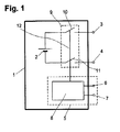
- FIG. 1 shows the housing 1 of an electrical storage, in particular a battery or a rechargeable battery, which has a plurality of storage elements, in particular galvanic cells.
- the cells 2 are connected to a positive pole (positive pole) 3 and to a negative pole (negative pole) 4.
- a turn-off device 9 In the connection between the cells 2 and the poles 3, 4 is a turn-off device 9 with two switches 10, 11 which are arranged in the line between the cells 2 and the positive pole 3 and in the line between the cells 2 and the negative terminal 4 are. By opening the switches 10, 11, the current-conducting connection between the cells 2 and the poles 3, 4 can be interrupted and the poles 3, 4 can be switched off.
- the electrical storage is preferably used as a voltage source for an electric drive on a boat, especially for outboard motors.
- a water sensor 5 is provided in the housing 1, a water sensor 5 is provided.
- the water sensor 5 comprises a measuring shadow 8 and two measuring contacts 6, 7, which are arranged outside the housing 1 or on its exterior.
- the measuring circuit 8 is connected via a control line 12 to the switches 10, 11.
- the measuring circuit 8 determines the electrical resistance between the two measuring contact 6, 7. If the measuring contacts 6, 7 come into contact with water, so changes the electrical resistance between the measuring contacts 6, 7. This change is interpreted by the measuring circuit 8 as the presence of water and the switches 10, 11 are controlled by the control line 12 and opened. The poles 3, 4 of the electrical storage are thus de-energized to avoid contact corrosion and to minimize further consequential damage.
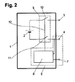
- FIG. 2 shows an alternative embodiment of the invention. This is different from the one in FIG. 1 version shown in that the negative pole 4 serves as a measuring contact. Incidentally, the same components are identified by the same reference numerals in all figures.
- the water detection is performed in this case by measuring an electrical variable, for example, the electrical resistance, between the negative terminal 4 and the second measuring contact 7.
- This approach has the advantage that the water detection takes place in the immediate vicinity of the one pole 4 of the electrical storage.
- FIG. 3 a further embodiment is shown in which two water sensors 5, 13 are provided.
- the water sensor 5 is as shown FIG. 2 described, connected to the negative terminal 4 of the electrical storage.
- the negative pole 4 is used as one of the two measuring contacts of the water sensor 5.
- the second water sensor 13 is executed, wherein the positive pole 3 of the electrical memory serves as one of the measuring contact 3, 14.
- the measuring circuit 8 registers the presence of water in the region of the negative pole 4, the measuring circuit 13 registers the presence of water in the region of the positive pole 3.
- This has advantages in batteries with large spatial extent. Batteries are generally installed horizontally, so that all battery poles 3, 4 have a same height above the water level. In case of an accident, it could come to an angle, in which then one of the battery terminals 3, 4 has significantly more time in contact with the incoming water. In the FIG. 3 shown variant of the invention then allows early shutdown of the memory, well before the second Speicherpol 3, 4 comes into contact with the water.
- FIG. 4 an electrical storage device according to the invention is shown in which a mechanical barrier 16 is provided in order to prevent unwanted contact between the battery poles 3, 4 and the measuring contact 7 during assembly of the storage or other marine components by the tool used.
- FIG. 4 shown electrical circuit corresponds to the circuit according to FIG. 2 .
- a mechanical barrier 16 for example in the form of an increase of the housing, is provided between the poles 3, 4 of the electrical storage.
- the barrier 16 is designed so that it is located in the straight-line connection as the crow flies between the two poles 3, 4. In this way, the unintentional production of an electrically conductive connection between the two poles 3, 4, for example by means of a tool, is prevented or at least made more difficult.
- the water sensor 5 is designed so that one of the poles 4 serves as a measuring contact, so it makes sense to provide the measuring contact on the side of the barrier 16, on which the pole 3 of the memory is arranged, which is not connected to Measuring circuit has.
- FIG. 5 an embodiment of the invention is shown in which in the event of an accident in which the water sensor 5 detects contact with water, not only the poles 3, 4, but also other electrical components 17, 18, 19 are turned off.
- the circuit shown the water sensor 5 corresponds to the in FIG. 2 shown circuit.
- the concept explained below is also in the circuits according to the FIGS. 1 or 3 applicable in a corresponding manner.
- a monitoring line 20 is additionally provided, which is connected to a low-voltage power source 21.
- a motor controller 17 which drives an electric motor 18, and another component 19 to the battery terminals 3, 4 are connected.
- the monitoring line 12 is also connected to the motor controller 17 and the other component 19.
- a switch 22 is provided in the monitoring line 20, via which the monitoring line 20 can be separated.
- the measuring circuit 8 In the case of a problem or accident detected by the water sensor 5, the measuring circuit 8 not only opens the switches 10, 11 to de-energize the battery terminals 3, 4, but also the monitoring line 20 is interrupted by opening the switch 22. The motor control 17 and the further component 19 is thereby signaled a problem. The engine controller 17 will shut off the electric motor 18 and the other component 19 will also be turned off. In this way, not only galvanic contact corrosion is prevented at the poles 3, 4, but also a damage to the other with the cells 2 conductively connected components 17, 18, 19 counteracted.
Landscapes
- Engineering & Computer Science (AREA)
- Chemical & Material Sciences (AREA)
- Combustion & Propulsion (AREA)
- Mechanical Engineering (AREA)
- Ocean & Marine Engineering (AREA)
- Manufacturing & Machinery (AREA)
- Chemical Kinetics & Catalysis (AREA)
- Electrochemistry (AREA)
- General Chemical & Material Sciences (AREA)
- Fluid Mechanics (AREA)
- Physics & Mathematics (AREA)
- Microelectronics & Electronic Packaging (AREA)
- Secondary Cells (AREA)
- Battery Mounting, Suspending (AREA)
- Connection Of Batteries Or Terminals (AREA)
- Investigating Or Analyzing Materials By The Use Of Electric Means (AREA)
Priority Applications (4)
| Application Number | Priority Date | Filing Date | Title |
|---|---|---|---|
| US14/442,047 US10096863B2 (en) | 2012-11-12 | 2013-11-11 | Electrical accumulator with water sensor |
| EP13796000.1A EP2920054B1 (fr) | 2012-11-12 | 2013-11-11 | Accumulateur électrique avec capteur d'eau |
| PCT/EP2013/003392 WO2014072071A1 (fr) | 2012-11-12 | 2013-11-11 | Accumulateur électrique pourvu d'un capteur d'eau |
| DK13796000.1T DK2920054T3 (da) | 2012-11-12 | 2013-11-11 | Elektrisk lagring med vandsensor |
Applications Claiming Priority (1)
| Application Number | Priority Date | Filing Date | Title |
|---|---|---|---|
| DE102012021994 | 2012-11-12 |
Publications (1)
| Publication Number | Publication Date |
|---|---|
| EP2730492A1 true EP2730492A1 (fr) | 2014-05-14 |
Family
ID=47721951
Family Applications (2)
| Application Number | Title | Priority Date | Filing Date |
|---|---|---|---|
| EP13000547.3A Withdrawn EP2730492A1 (fr) | 2012-11-12 | 2013-02-03 | Accumulateur électrique avec capteur d'eau |
| EP13796000.1A Active EP2920054B1 (fr) | 2012-11-12 | 2013-11-11 | Accumulateur électrique avec capteur d'eau |
Family Applications After (1)
| Application Number | Title | Priority Date | Filing Date |
|---|---|---|---|
| EP13796000.1A Active EP2920054B1 (fr) | 2012-11-12 | 2013-11-11 | Accumulateur électrique avec capteur d'eau |
Country Status (4)
| Country | Link |
|---|---|
| US (1) | US10096863B2 (fr) |
| EP (2) | EP2730492A1 (fr) |
| DK (1) | DK2920054T3 (fr) |
| WO (1) | WO2014072071A1 (fr) |
Cited By (1)
| Publication number | Priority date | Publication date | Assignee | Title |
|---|---|---|---|---|
| EP3530560A1 (fr) * | 2018-02-22 | 2019-08-28 | Torqeedo GmbH | Dispositif de surveillance d'un entraînement de bateau |
Families Citing this family (4)
| Publication number | Priority date | Publication date | Assignee | Title |
|---|---|---|---|---|
| EP2730493A1 (fr) | 2012-11-12 | 2014-05-14 | Torqeedo GmbH | Bateau avec système haute tension |
| DK2920060T3 (en) | 2012-11-12 | 2018-10-22 | Torqeedo Gmbh | BOAT WITH ELECTRIC DRIVE |
| CN116487794A (zh) | 2017-01-09 | 2023-07-25 | 米沃奇电动工具公司 | 用于向电气设备提供输出电力的设备 |
| US10714926B2 (en) * | 2017-07-06 | 2020-07-14 | International Business Machines Corporation | Self-disconnecting power source apparatus |
Citations (4)
| Publication number | Priority date | Publication date | Assignee | Title |
|---|---|---|---|---|
| US5292269A (en) * | 1993-02-19 | 1994-03-08 | Plost Gerald N | Trolling motor automatic disconnect |
| US5516312A (en) * | 1994-08-26 | 1996-05-14 | Reed; Steven L. | Engine safety interlock |
| EP1806280A1 (fr) * | 2006-01-05 | 2007-07-11 | Torqeedo GmbH | Moteur hors-bord pour bateaux |
| US20110244739A1 (en) * | 2010-03-31 | 2011-10-06 | Suzuki Motor Corporation | Electric outboard motor |
Family Cites Families (6)
| Publication number | Priority date | Publication date | Assignee | Title |
|---|---|---|---|---|
| US6669516B1 (en) | 2002-08-20 | 2003-12-30 | Royce H. Husted | Weed-resistant outboard motor drive system |
| US7898219B2 (en) * | 2008-02-25 | 2011-03-01 | Jimmie Doyle Felps | On-board battery supervisor |
| DE102009020559B4 (de) * | 2009-05-08 | 2011-05-05 | Auto-Kabel Management Gmbh | Kurzschlusssicherung für eine Elektrofahrzeugbatterie |
| US20110135984A1 (en) | 2009-12-04 | 2011-06-09 | Ekchian Jack A | Safety device for electric and hybrid electric vehicle energy storage systems |
| EP2730493A1 (fr) | 2012-11-12 | 2014-05-14 | Torqeedo GmbH | Bateau avec système haute tension |
| DK2920060T3 (en) | 2012-11-12 | 2018-10-22 | Torqeedo Gmbh | BOAT WITH ELECTRIC DRIVE |
-
2013
- 2013-02-03 EP EP13000547.3A patent/EP2730492A1/fr not_active Withdrawn
- 2013-11-11 US US14/442,047 patent/US10096863B2/en active Active
- 2013-11-11 WO PCT/EP2013/003392 patent/WO2014072071A1/fr active Application Filing
- 2013-11-11 EP EP13796000.1A patent/EP2920054B1/fr active Active
- 2013-11-11 DK DK13796000.1T patent/DK2920054T3/da active
Patent Citations (4)
| Publication number | Priority date | Publication date | Assignee | Title |
|---|---|---|---|---|
| US5292269A (en) * | 1993-02-19 | 1994-03-08 | Plost Gerald N | Trolling motor automatic disconnect |
| US5516312A (en) * | 1994-08-26 | 1996-05-14 | Reed; Steven L. | Engine safety interlock |
| EP1806280A1 (fr) * | 2006-01-05 | 2007-07-11 | Torqeedo GmbH | Moteur hors-bord pour bateaux |
| US20110244739A1 (en) * | 2010-03-31 | 2011-10-06 | Suzuki Motor Corporation | Electric outboard motor |
Cited By (3)
| Publication number | Priority date | Publication date | Assignee | Title |
|---|---|---|---|---|
| EP3530560A1 (fr) * | 2018-02-22 | 2019-08-28 | Torqeedo GmbH | Dispositif de surveillance d'un entraînement de bateau |
| CN110182345A (zh) * | 2018-02-22 | 2019-08-30 | 托奇多有限责任公司 | 用于监测船舶驱动装置的装置 |
| US11001360B2 (en) | 2018-02-22 | 2021-05-11 | Torqeedo Gmbh | Device for monitoring a boat drive |
Also Published As
| Publication number | Publication date |
|---|---|
| US20150288036A1 (en) | 2015-10-08 |
| EP2920054B1 (fr) | 2020-01-01 |
| US10096863B2 (en) | 2018-10-09 |
| DK2920054T3 (da) | 2020-03-02 |
| EP2920054A1 (fr) | 2015-09-23 |
| WO2014072071A1 (fr) | 2014-05-15 |
Similar Documents
| Publication | Publication Date | Title |
|---|---|---|
| EP2427941B1 (fr) | Protection contre les courts-circuits de la batterie d'un véhicule électrique | |
| DE102012109430B4 (de) | Automatisches Batterieentladeverfahren nach einem Crash | |
| EP2920054B1 (fr) | Accumulateur électrique avec capteur d'eau | |
| DE102015105426B4 (de) | Sicherheitsvorrichtung für einen wiederaufladbaren elektrischen Energiespeicher, Verfahren zur Unterbindung eines elektrischen Stromflusses eines wiederaufladbaren elektrischen Energiespeichers und Batteriesystem mit dieser Sicherheitsvorrichtung | |
| DE102010061815B4 (de) | Integrierter Niederspannungs- und Hochspannungsanschlusskasten | |
| EP3392070A1 (fr) | Bloc-batterie et véhicule électrique | |
| WO2010057724A1 (fr) | Véhicule, en particulier véhicule hybride, avec un équipement électrique | |
| DE102013217006A1 (de) | Schalter mit einem Reed-Relais für eine Hochspannungsverriegelungsschleife (HVIL-Schalter) | |
| DE102011014343A1 (de) | Sicherungsvorrichtung für eine Spannungsversorgung eines Kraftfahrzeugs | |
| DE102015002069B4 (de) | Batterie und Kraftfahrzeug | |
| DE112018003415T5 (de) | Energiespeichervorrichtung, fahrzeug und motorrad | |
| WO2012155942A2 (fr) | Ensemble de batteries pour une automobile | |
| DE102010045904A1 (de) | Energiespeichereinrichtung mit Kurzschlusssicherungsschaltung | |
| DE102016212986A1 (de) | Flüssigkeitsmessvorrichtung und Messkopfvorrichtung zur Feuchtigkeitsdetektion, insbesondere in Behältnissen für flüssigkeitssensitive Elektrik- und/oder Elektronikkomponenten in Straßenfahrzeugen | |
| WO2014191135A1 (fr) | Séparation de modules dans des systèmes de batterie en cas d'accidents | |
| DE102012013497B4 (de) | Batterie für ein Fahrzeug, Verwendung einer solchen Batterie und Verfahren zum Betreiben eines Fahrzeugs | |
| EP2792013A1 (fr) | Système de batterie et véhicule à moteur | |
| DE102014006829A1 (de) | Elektrischer Speicher mit Wassersensor | |
| DE102016107706A1 (de) | Ansteuerungsvorrichtung für eine pyrotechnische Sicherungsvorrichtung | |
| DE102014208543A1 (de) | Batteriezelleinrichtung mit einer Batteriezelle und einer Überwachungselektronik zum Überwachen der Batteriezelle und entsprechendes Verfahren zum Betreiben und Überwachen einer Batteriezelle | |
| WO2015173000A1 (fr) | Procédé d'exploitation d'un ensemble accumulateur d'énergie, système de gestion de batterie pour la mise en œuvre d'un tel procédé, et ensemble accumulateur d'énergie doté d'un tel système de gestion de batterie | |
| DE102017221935A1 (de) | Schutzvorrichtung und Verfahren zur Absicherung eines Hochvoltnetzes sowie elektrisches Antriebssystem | |
| DE102015200316A1 (de) | Batterie und Batteriesystem aufweisend eine Batterie | |
| EP3314275B1 (fr) | Dispositif de mesure pour l'identification d'une fonction déficiente dans un dispositif accumulateur d'énergie | |
| EP2791391B1 (fr) | Batterie, véhicule à moteur et procédé permettant de faire fonctionner une batterie |
Legal Events
| Date | Code | Title | Description |
|---|---|---|---|
| PUAI | Public reference made under article 153(3) epc to a published international application that has entered the european phase |
Free format text: ORIGINAL CODE: 0009012 |
|
| 17P | Request for examination filed |
Effective date: 20130203 |
|
| AK | Designated contracting states |
Kind code of ref document: A1 Designated state(s): AL AT BE BG CH CY CZ DE DK EE ES FI FR GB GR HR HU IE IS IT LI LT LU LV MC MK MT NL NO PL PT RO RS SE SI SK SM TR |
|
| AX | Request for extension of the european patent |
Extension state: BA ME |
|
| STAA | Information on the status of an ep patent application or granted ep patent |
Free format text: STATUS: THE APPLICATION IS DEEMED TO BE WITHDRAWN |
|
| 18D | Application deemed to be withdrawn |
Effective date: 20141115 |