EP2730468A1 - Vehicle bumper reinforcement - Google Patents
Vehicle bumper reinforcement Download PDFInfo
- Publication number
- EP2730468A1 EP2730468A1 EP12807205.5A EP12807205A EP2730468A1 EP 2730468 A1 EP2730468 A1 EP 2730468A1 EP 12807205 A EP12807205 A EP 12807205A EP 2730468 A1 EP2730468 A1 EP 2730468A1
- Authority
- EP
- European Patent Office
- Prior art keywords
- vehicle
- portions
- bumper reinforcement
- projecting
- low strength
- Prior art date
- Legal status (The legal status is an assumption and is not a legal conclusion. Google has not performed a legal analysis and makes no representation as to the accuracy of the status listed.)
- Withdrawn
Links
- 230000002787 reinforcement Effects 0.000 title claims abstract description 58
- 239000000463 material Substances 0.000 claims description 17
- 239000002184 metal Substances 0.000 claims description 10
- 238000010521 absorption reaction Methods 0.000 abstract description 11
- 230000000694 effects Effects 0.000 description 13
- 230000000052 comparative effect Effects 0.000 description 10
- 238000010586 diagram Methods 0.000 description 7
- 238000005452 bending Methods 0.000 description 3
- 238000005516 engineering process Methods 0.000 description 3
- 238000010791 quenching Methods 0.000 description 3
- 101000856746 Bos taurus Cytochrome c oxidase subunit 7A1, mitochondrial Proteins 0.000 description 2
- 229910000831 Steel Inorganic materials 0.000 description 2
- 238000011835 investigation Methods 0.000 description 2
- 238000004519 manufacturing process Methods 0.000 description 2
- 230000000630 rising effect Effects 0.000 description 2
- 239000010959 steel Substances 0.000 description 2
- 238000010998 test method Methods 0.000 description 2
- 230000003247 decreasing effect Effects 0.000 description 1
- 238000006073 displacement reaction Methods 0.000 description 1
- 230000000171 quenching effect Effects 0.000 description 1
- 229920003002 synthetic resin Polymers 0.000 description 1
- 239000000057 synthetic resin Substances 0.000 description 1
Images





Classifications
-
- B—PERFORMING OPERATIONS; TRANSPORTING
- B60—VEHICLES IN GENERAL
- B60R—VEHICLES, VEHICLE FITTINGS, OR VEHICLE PARTS, NOT OTHERWISE PROVIDED FOR
- B60R19/00—Wheel guards; Radiator guards, e.g. grilles; Obstruction removers; Fittings damping bouncing force in collisions
- B60R19/02—Bumpers, i.e. impact receiving or absorbing members for protecting vehicles or fending off blows from other vehicles or objects
- B60R19/18—Bumpers, i.e. impact receiving or absorbing members for protecting vehicles or fending off blows from other vehicles or objects characterised by the cross-section; Means within the bumper to absorb impact
-
- B—PERFORMING OPERATIONS; TRANSPORTING
- B60—VEHICLES IN GENERAL
- B60R—VEHICLES, VEHICLE FITTINGS, OR VEHICLE PARTS, NOT OTHERWISE PROVIDED FOR
- B60R19/00—Wheel guards; Radiator guards, e.g. grilles; Obstruction removers; Fittings damping bouncing force in collisions
- B60R19/56—Fittings damping bouncing force in truck collisions, e.g. bumpers; Arrangements on high-riding vehicles, e.g. lorries, for preventing vehicles or objects from running thereunder
-
- B—PERFORMING OPERATIONS; TRANSPORTING
- B60—VEHICLES IN GENERAL
- B60R—VEHICLES, VEHICLE FITTINGS, OR VEHICLE PARTS, NOT OTHERWISE PROVIDED FOR
- B60R19/00—Wheel guards; Radiator guards, e.g. grilles; Obstruction removers; Fittings damping bouncing force in collisions
- B60R19/02—Bumpers, i.e. impact receiving or absorbing members for protecting vehicles or fending off blows from other vehicles or objects
- B60R19/18—Bumpers, i.e. impact receiving or absorbing members for protecting vehicles or fending off blows from other vehicles or objects characterised by the cross-section; Means within the bumper to absorb impact
- B60R2019/1806—Structural beams therefor, e.g. shock-absorbing
- B60R2019/1813—Structural beams therefor, e.g. shock-absorbing made of metal
-
- B—PERFORMING OPERATIONS; TRANSPORTING
- B60—VEHICLES IN GENERAL
- B60R—VEHICLES, VEHICLE FITTINGS, OR VEHICLE PARTS, NOT OTHERWISE PROVIDED FOR
- B60R19/00—Wheel guards; Radiator guards, e.g. grilles; Obstruction removers; Fittings damping bouncing force in collisions
- B60R19/02—Bumpers, i.e. impact receiving or absorbing members for protecting vehicles or fending off blows from other vehicles or objects
- B60R19/18—Bumpers, i.e. impact receiving or absorbing members for protecting vehicles or fending off blows from other vehicles or objects characterised by the cross-section; Means within the bumper to absorb impact
- B60R2019/186—Additional energy absorbing means supported on bumber beams, e.g. cellular structures or material
Definitions
- the present invention relates to a bumper reinforcement for a vehicle, and particularly to improvement of a bumper reinforcement having a function of preventing a vehicle from running onto or under another vehicle.
- a bumper reinforcement for a vehicle has been proposed, which is configured by a metal plate material, and which is formed by press working so as to have a plurality of projecting portions that are provided at a distance from each other in a vehicle up-down direction and project toward a vehicle outer side, the bumper reinforcement having a longitudinal shape that is elongated in a vehicle width direction.
- a device described in Patent Document 1 is one example thereof, and a high-strength bumper reinforcement with high tensile strength is obtained by hot press forming (hot stamping forming).
- Patent Document 2 a technology is proposed in which, in a case where quench hardening is performed by hot press forming, in order to prevent a sharp decrease in a load due to buckling (bending) of a load-input portion, a low strength portion is provided by locally moderating hardening, and thus, a sudden decrease in the load is suppressed to obtain excellent collision energy absorption performance.
- Patent Document 3 proposes a technology in which a height-raising wall for preventing a vehicle from running under another vehicle is fixedly provided integrally with a bumper reinforcement.
- the present invention has been made in view of the above-described circumstances, and an object thereof is to obtain excellent collision energy absorption performance, and to obtain a function of preventing a vehicle from running onto or under another vehicle without increasing the number of components and weight.
- the first aspect of the invention provides a bumper reinforcement for a vehicle, which is configured by a metal plate material, and which is formed by press working so as to have a plurality of projecting portions that are provided at a distance from each other in a vehicle up-down direction, and project toward a vehicle outer side, the bumper reinforcement having a longitudinal shape that is elongated in a vehicle width direction, and the bumper reinforcement being characterized in that low strength portions, each of which has a width expanded in the vehicle up-down direction, and in each of which the number of the projecting portions is relatively small or a projecting dimension of the projecting portion is reduced, are provided at a plurality of locations inside a pair of support portions fixed to a vehicle body in the vehicle width direction, the locations being symmetrical with respect to a center in the vehicle width direction.
- the second aspect of the invention provides the bumper reinforcement for a vehicle recited in the first aspect of the invention, wherein (a) in a general portion other than the low strength portions, a pair of the projecting portions is provided to form an M-shaped section in the vehicle up-down direction, (b) in each of the low strength portions, the number of the projecting portions is one, and the projecting dimension of the projecting portion is the same as that of the projecting portions in the general portion, and each of the low strength portions has a section having an inverted shallow dish shape extending in the vehicle up-down direction, and (c) sectional lengths of the general portion and each of the low strength portions in the vehicle up-down direction are substantially the same.
- the third aspect of the invention provides the bumper reinforcement for a vehicle recited in the first or second aspect of the invention, wherein a width of each of the low strength portions is expanded upwardly or downwardly in the vehicle up-down direction.
- the bumper reinforcement for a vehicle since the low strength portions are provided at a plurality of locations inside a pair of support portions and the locations being symmetrical with respect to a center in the vehicle width direction, the bumper reinforcement for a vehicle is easily deformed at the low strength portions, and a sharp decrease in a load due to buckling of a load-input portion is suppressed, and thus, it is possible to obtain excellent collision energy absorption performance.
- each of the low strength portions of the present invention is characterized in that the number of the projecting portions is small or a projecting dimension of the projecting portion is reduced, strength against a collision load from the projecting direction of the projecting portion is reduced.
- each of the low strength portions Since the width of each of the low strength portions is expanded in the vehicle up-down direction, the function of preventing the vehicle from running onto or under another vehicle is obtained by the low strength portions, and thus, the vehicle is restrained from running onto and running under the other vehicle without increasing the number of components and weight.
- each of the low strength portions while in a general portion other than the low strength portions, a pair of the projecting portions is provided to form an M-shaped section, in each of the low strength portions, the number of the projecting portions is one, and each of the low strength portions has a section having an inverted shallow dish shape extending in the vehicle up-down direction. Therefore, strength against a collision load of each of the low strength portions is appropriately reduced as compared to the general portion. Since sectional lengths of the general portion and each of the low strength portions in the vehicle up-down direction are substantially the same, it is possible to perform press working using the metal plate material having a constant material width dimension in the vehicle up-down direction, thereby improving a material yield and reducing manufacturing cost.
- a bumper reinforcement for a vehicle according to the present invention is applicable to a bumper attached to a front side of a vehicle and a bumper attached to a rear side of a vehicle, but may be applied to only either one of the above-described bumpers.
- a longitudinal shape of a bumper reinforcement in other words, a shape in a planar view seen from above a vehicle is a shape that is smoothly curved so that, for example, a central portion projects in a direction toward an outer side of the vehicle (frontward or rearward), but may also be a substantially linear shape, and the bumper reinforcement may have various forms, for example, a form in which only both end portions are inclined or curved toward a vehicle body side.
- a plurality of low strength portions are provided, for example, at two locations symmetrical with respect to a center in a vehicle width direction so as to be separated from the center, but may also be provided at four or more locations. It is preferable that each of the low strength portions should be provided to have a shape that changes smoothly from a general portion so that stress concentration does not occur at a boundary with the general portion other than the low strength portions, and for example, the low strength portions bulge in an arc shape in a vehicle up-down direction.
- the portion that includes support portions and that is other than the low strength portions may have a same sectional shape such as an M shape, but the support portions may also have a different sectional shape.
- Each of the low strength portions is configured so as to have, for example, one projecting portion and a section in an inverted shallow dish shape extending in the vehicle up-down direction (a shape in which a bottom side of a dish projects toward a vehicle outer side) as in the second invention, but the number of the projecting portions may be the same as that in the general portion, and a projecting dimension of the projecting portion may be reduced and a width of the low strength portion in the vehicle up-down direction may be expanded.
- sectional lengths of the general portion and each of the low strength portions in the vehicle up-down direction are substantially the same.
- the sectional lengths of the general portion and each of the low strength portions in the vehicle up-down direction do not need to be the same, and may be appropriately determined.
- the projecting dimension of the projecting portions in the general portion is the same as that of the projecting portion in each of the low strength portions.
- the low strength portions are provided.
- the low strength portions each of which has a width expanded upwardly or downwardly in the vehicle up-down direction
- the low strength portions may be provided.
- a function of the low strength portions for preventing a vehicle from running onto or under another vehicle does not necessarily need to achieve both an effect of preventing the vehicle from running onto the other vehicle and an effect of preventing the vehicle from running under the other vehicle, and may achieve at least one of the effect of preventing the vehicle from running onto the other vehicle and the effect of preventing the vehicle from running under the other vehicle.
- the bumper reinforcement In press working for forming the bumper reinforcement, for example, mainly bending may be performed, and drawing may be also performed. It is desirable that the bumper reinforcement should be formed by performing press working one time, using a pair of dies having a forming surface with an intended sectional shape. If necessary, flat flanges may be provided on respective side portions of the bumper reinforcement in the vehicle up-down direction, so as to project toward an upper side and a lower side of the vehicle.
- a steel plate for hot press forming which is able to be hardened by quenching through hot press forming, is suitably used as a metal plate material.
- FIG. 1(a) is a perspective view
- FIG 1(b) is an enlarged view of a section taken along IB - IB in FIG 1(a)
- FIG 1(c) is an enlarged view of a section taken along IC - IC in FIG. 1(a)
- FIG 2 is a view that also shows the bumper reinforcement 10
- FIG 2(a) is a plan view seen from above in a state where the bumper reinforcement 10 is arranged in the vehicle
- FIG 2(b) is a front view seen from a front side of the vehicle.
- FIG 3 is a plan view showing a rectangular metal plate material 12, which is a material of the bumper reinforcement 10.
- a steel plate for hot press forming is used, which is bent into a given shape by hot press forming, and is given high strength up to tensile strength of 1400 MPa or higher through quench hardening.
- the bumper reinforcement 10 has a longitudinal shape that is elongated in a vehicle width direction that is a right-left direction in FIG 2(a) , and in the plan view shown in FIG 2(a) , the bumper reinforcement 10 includes a linear portion 14 located at a center portion in the vehicle width direction, a pair of inclined portions 16 located on respective end portions, and a pair of curved portions 18 that smoothly connects the linear portion 14 and the inclined portions 16.
- the bumper reinforcement 10 is configured to be bilaterally symmetrical with respect to the center in the vehicle width direction, and portions of the pair of inclined portions 16 on respective ends are fixed to side members 22 on the right and left, which serve as vehicle-side members, through bumper stays 20, the portions of the pair of inclined portions 16 receding toward the vehicle body side.
- the portions of the inclined portions 16, which are fixed to the bumper stays 20, correspond to support portions.
- a bumper body 24 made of a synthetic resin is arranged outside the bumper reinforcement 10.
- a pair of projecting portions 30, 32 projecting in an inverted U shape toward the vehicle outer side (in this example, frontward) is provided at a distance from each other in the vehicle up-down direction, through a connecting portion 34 as shown in FIG 1(b) , thus forming an M-shaped section as a whole.
- flat flanges 36, 38 are provided so as to project upward and downward.
- Each of bent portions in the M-shaped section is bent relatively angularly, and each of the pair of projecting portions 30, 32 has a trapezoidal shape in which a width dimension is reduced toward a distal end side.
- the connecting portion 34 is in the form of a straight line, in other words, a flat surface.
- the connecting portion 34 and the flanges 36, 38 are located within a common plane, and are arranged in a substantially vertical posture.
- the left direction in FIG 1(b) is the vehicle front side.
- the paired curved portions 18 of the bumper reinforcement 10 are provided at two positions symmetrical with respect to the center in the vehicle width direction, and each of the curved portions 18 is configured by a single projecting portion 40 as evident from the section in the vehicle up-down direction shown in FIG 1(c) .
- a projecting dimension of the projecting portion 40 toward the front of the vehicle is the same as those of the projecting portions 30, 32 described above, but the projecting portion 40 has a large width dimension in the vehicle up-down direction, and has an inverted shallow dish shape in the section in the vehicle up-down direction shown in FIG. 1(c) .
- each of the curved portions 18 in the up-down direction is larger than those of the linear portion 14 and each of the inclined portions 16, and the width of each of the curved portions 18 is expanded upwardly and downwardly in the vehicle up-down direction, each of the curved portions 18 smoothly bulges in an arc shape upwardly and downwardly so as to be connected smoothly with upper and lower end edges of the linear portion 14 and the inclined portion 16, as evident in FIG. 1(a) and FIG. 2(b) .
- Sectional lengths in the sectional shapes in the vehicle up-down direction shown in FIG 1(b) and FIG 1(c) are substantially the same, and as shown in FIG 3 , the bumper reinforcement 10 is manufactured by performing press working on the rectangular metal plate material 12 having a constant material width dimension in the vehicle up-down direction (a width dimension in the up-down direction in FIG. 3 ).
- the flanges 36, 38 are respectively provided continuously from the foregoing linear portion 14 and the inclined portions 16.
- the curved portions 18, each of which is configured by the single projecting portion 40 correspond to low strength portions
- the linear portion 14 and the inclined portions 16, which have the pair of projecting portions 30, 32 correspond to a general portion.
- a center line S in FIG 1(b) and 1(c) is a center line of the linear portion 14 and the inclined portions 16 in the up-down direction shown in FIG 1(b) , and the width of each of the curved portions 18 in FIG 1(c) is expanded upward and downward substantially equally in the up-down direction.
- the bumper reinforcement for a vehicle 10 in this example since the curved portions 18 with low strength are provided at two positions that are symmetrical with respect to the center in the vehicle width direction, the bumper reinforcement for a vehicle 10 is easily deformed at the curved portions 18, and a sharp decrease in a load due to buckling of a load-input portion is suppressed, and thus, it is possible to obtain excellent collision energy absorption performance.
- each of the curved portions 18 is configured by the single projecting portion 40, strength against a collision load from the projecting direction of the projecting portion 40 (from the front of the vehicle) is reduced.
- each of the curved portions 18 Since the width of each of the curved portions 18 is expanded in the vehicle up-down direction, the function of preventing the vehicle from running onto or under another vehicle is obtained by the curved portions 18, and thus, the vehicle is restrained from running onto and running under the other vehicle without increasing the number of components and weight.
- the width of each of the curved portions 18 is expanded upwardly and downwardly in the vehicle up-down direction, it is possible to adequately obtain both the effect of preventing the vehicle from running onto the other vehicle and the effect of preventing the vehicle from running under the other vehicle.
- each of the curved portions 18 is configured by the single projecting portion 40, and has a section with the inverted shallow dish shape extending in the vehicle up-down direction, and therefore, strength of the curved portions 18 against the collision load is adequately reduced as compared to the linear portion 14 and the inclined portions 16.
- each of the inclined portions 16, and each of the curved portions 18 in the vehicle up-down direction are substantially the same, it is possible to perform press working using the metal plate material 12 having a constant material width dimension in the vehicle up-down direction, thereby improving a material yield and reducing manufacturing cost.
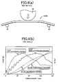
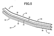
- FIG 4 is a view explaining a result of an investigation on differences in collision energy absorption performance using the bumper reinforcement 10 of this example and a comparative product 50 shown in FIG. 5 .
- a sectional shape of a curved portion 52 is the same as those of the foregoing linear portion 14 and the inclined portions 16, and thus, the curved portion 52 has the M-shaped section as shown in FIG 1(b) .
- FIG 4(a) is a view explaining a test method, in which portions of the inclined portions 16, which were located near the support portions, were placed on and fixed to a pair of support stands 60, a colliding piece 62 having a semicircular arc-shaped distal end was caused to collide with a center portion in the vehicle width direction at a given speed, a load change at that time was measured, and an EA amount (an energy absorption amount) was obtained.
- the EA amount corresponds to an integral value of a load.
- FIG 4(b) is a result of the test, in which solid lines represent the product according to the present invention (the bumper reinforcement 10), in other words, the case where there are low strength portions, and dashed lines represent the comparative product 50, in other words, the case where there is no low strength portion.
- dashed lines represent the comparative product 50, in other words, the case where there is no low strength portion.
- FIG. 6 is a perspective view of the tested products after the test
- FIG 6(a) shows the product according to the present invention (the bumper reinforcement 10)
- FIG 6(b) shows the comparative product 50.
- the comparative product 50 is buckled at a portion near the center of the linear portion 14 that serves as the load-input portion.
- the linear portion 14 is not buckled and is only curved gently.
- Each of the curved portions 18 in the foregoing example is configured by the single projecting portion 40.
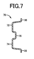
- a pair of projecting portions 72, 74 is connected with each other by a relatively-shallow connecting portion 76 as in a curved portion 70 shown in FIG. 7
- strength against a collision load from the front of the vehicle is reduced as compared to that of the linear portion 14 and the inclined portions 16, and the curved portion 70 may be used as a low strength portion.
- FIG 7 is a sectional view corresponding to FIG 1(c) .
- each of curved portions 82 of a bumper reinforcement for a vehicle 80 shown in FIG 8 and FIG 9 has a sectional shape shown in FIG 8(c) that is the same as that of the foregoing curved portion 18, but is different from the foregoing curved portion 18 in that a width is expanded only upwardly.
- the effect of preventing the vehicle from running onto the other vehicle in front of the vehicle is not obtained.
- an upward projecting dimension is larger than that of the curved portion 18, the effect of preventing the vehicle from running under the other vehicle in front of the vehicle is obtained even more appropriately, and this bumper reinforcement for a vehicle 80 is proactively applied to a vehicle in which a bumper is located at a low position, for example.
- FIG 8 and FIG 9 are views corresponding to FIG 1 and FIG 2 .
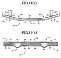
- FIG 10 and FIG. 11 are views corresponding to FIG 1 and FIG. 2 .
- metal plate material 14 linear portion (support portions, general portion) 16: inclined portion (general portion) 18, 70, 82, 92: curved portion (low strength portions) 30, 32, 40, 72, 74: projecting portion
Landscapes
- Engineering & Computer Science (AREA)
- Mechanical Engineering (AREA)
- Body Structure For Vehicles (AREA)
- Blow-Moulding Or Thermoforming Of Plastics Or The Like (AREA)
Abstract
Description
- The present invention relates to a bumper reinforcement for a vehicle, and particularly to improvement of a bumper reinforcement having a function of preventing a vehicle from running onto or under another vehicle.
- A bumper reinforcement for a vehicle has been proposed, which is configured by a metal plate material, and which is formed by press working so as to have a plurality of projecting portions that are provided at a distance from each other in a vehicle up-down direction and project toward a vehicle outer side, the bumper reinforcement having a longitudinal shape that is elongated in a vehicle width direction. A device described in Patent Document 1 is one example thereof, and a high-strength bumper reinforcement with high tensile strength is obtained by hot press forming (hot stamping forming). In Patent Document 2, a technology is proposed in which, in a case where quench hardening is performed by hot press forming, in order to prevent a sharp decrease in a load due to buckling (bending) of a load-input portion, a low strength portion is provided by locally moderating hardening, and thus, a sudden decrease in the load is suppressed to obtain excellent collision energy absorption performance. Also, Patent Document 3 proposes a technology in which a height-raising wall for preventing a vehicle from running under another vehicle is fixedly provided integrally with a bumper reinforcement.
-
- Patent Document 1: Japanese Patent Application Publication No.
2007-38756 - Patent Document 2: Japanese Patent Application Publication No.
2007-290582 - Patent Document 3: Japanese Patent Application Publication No.
2009-1199 - Therefore, by applying the technology described in the cited Document 2 to the cited Document 1, it is possible to obtain excellent collision energy absorption performance. However, a function of preventing a vehicle from running onto or under another vehicle is not obtained, and if a separate member is fixedly provided as in the cited Document 3, there is a problem that the number of components and weight are increased, and thus full satisfaction is not necessarily afforded.
- The present invention has been made in view of the above-described circumstances, and an object thereof is to obtain excellent collision energy absorption performance, and to obtain a function of preventing a vehicle from running onto or under another vehicle without increasing the number of components and weight.
- To achieve the object, the first aspect of the invention provides a bumper reinforcement for a vehicle, which is configured by a metal plate material, and which is formed by press working so as to have a plurality of projecting portions that are provided at a distance from each other in a vehicle up-down direction, and project toward a vehicle outer side, the bumper reinforcement having a longitudinal shape that is elongated in a vehicle width direction, and the bumper reinforcement being characterized in that low strength portions, each of which has a width expanded in the vehicle up-down direction, and in each of which the number of the projecting portions is relatively small or a projecting dimension of the projecting portion is reduced, are provided at a plurality of locations inside a pair of support portions fixed to a vehicle body in the vehicle width direction, the locations being symmetrical with respect to a center in the vehicle width direction.
- The second aspect of the invention provides the bumper reinforcement for a vehicle recited in the first aspect of the invention, wherein (a) in a general portion other than the low strength portions, a pair of the projecting portions is provided to form an M-shaped section in the vehicle up-down direction, (b) in each of the low strength portions, the number of the projecting portions is one, and the projecting dimension of the projecting portion is the same as that of the projecting portions in the general portion, and each of the low strength portions has a section having an inverted shallow dish shape extending in the vehicle up-down direction, and (c) sectional lengths of the general portion and each of the low strength portions in the vehicle up-down direction are substantially the same.
- The third aspect of the invention provides the bumper reinforcement for a vehicle recited in the first or second aspect of the invention, wherein a width of each of the low strength portions is expanded upwardly or downwardly in the vehicle up-down direction.
- In the bumper reinforcement for a vehicle as described above, since the low strength portions are provided at a plurality of locations inside a pair of support portions and the locations being symmetrical with respect to a center in the vehicle width direction, the bumper reinforcement for a vehicle is easily deformed at the low strength portions, and a sharp decrease in a load due to buckling of a load-input portion is suppressed, and thus, it is possible to obtain excellent collision energy absorption performance. In this case, since each of the low strength portions of the present invention is characterized in that the number of the projecting portions is small or a projecting dimension of the projecting portion is reduced, strength against a collision load from the projecting direction of the projecting portion is reduced. Since the width of each of the low strength portions is expanded in the vehicle up-down direction, the function of preventing the vehicle from running onto or under another vehicle is obtained by the low strength portions, and thus, the vehicle is restrained from running onto and running under the other vehicle without increasing the number of components and weight.
- In the second aspect of the invention, while in a general portion other than the low strength portions, a pair of the projecting portions is provided to form an M-shaped section, in each of the low strength portions, the number of the projecting portions is one, and each of the low strength portions has a section having an inverted shallow dish shape extending in the vehicle up-down direction. Therefore, strength against a collision load of each of the low strength portions is appropriately reduced as compared to the general portion. Since sectional lengths of the general portion and each of the low strength portions in the vehicle up-down direction are substantially the same, it is possible to perform press working using the metal plate material having a constant material width dimension in the vehicle up-down direction, thereby improving a material yield and reducing manufacturing cost.
-
-
FIG 1 is a diagram of the bumper reinforcement for a vehicle that is an example of the present invention; (a) is a perspective view, (b) is an enlarged view of a section taken along IB - IB in (a), and (c) is an enlarged view of a section taken along IC - ZC in (a). -
FIG. 2 is a diagram of the bumper reinforcement for a vehicle inFIG 1; (a) is a plan view seen from above in a state where the bumper reinforcement is arranged in the vehicle, and (b) is a front view seen from a front side of the vehicle. -
FIG. 3 is a plan view showing a rectangular metal plate material, which is a material of the bumper reinforcement inFIG. 1 . -
FIG 4 is a view explaining a result of an investigation on characteristics of a load and an EA amount (an energy absorption amount) using the bumper reinforcement inFIG 1 and a comparative product; (a) is a view explaining a test method, (b) is a result of the test. -
FIG. 5 is a perspective view of the comparative product used in the test ofFIG 4 . -
FIG 6 is perspective views of the tested products after the test ofFIG 4 corresponding toFIG 1(a) andFIG 5 , respectively; (a) shows the product according to the present invention, and (b) shows the comparative product. -
FIG 7 is a diagram for explaining the other example of the present invention and a cross section of the carved portion (low strength portion) corresponding toFIG 1 (c) . -
FIG 8 is a diagram for explaining yet another example of the present invention and corresponds toFIG. 1; (a) is a perspective view, (b) is an enlarged view of a section taken along VIIIB - VIIIB in (a), and (c) is an enlarged view of a section taken along VIIIC - VIIIC in (a). -
FIG 9 is a diagram of the bumper reinforcement for a vehicle in an example ofFIG 8 and corresponds toFIG. 2 ;(a) is a plan view seen from above in a state where the bumper reinforcement is arranged in the vehicle, and (b) is a front view seen from a front side of the vehicle. -
FIG 10 is a diagram for explaining yet another example of the present invention and corresponds toFIG 1; (a) is a perspective view, (b) is an enlarged view of a section taken along XB - XB in (a), and (c) is an enlarged view of a section taken along XC -XC in (a). -
FIG 11 is a diagram of the bumper reinforcement for a vehicle in an example ofFIG 10 and corresponds toFIG 2 ;(a) is a plan view seen from above in a state where the bumper reinforcement is arranged in the vehicle, and (b) is a front view seen from a front side of the vehicle. - A bumper reinforcement for a vehicle according to the present invention is applicable to a bumper attached to a front side of a vehicle and a bumper attached to a rear side of a vehicle, but may be applied to only either one of the above-described bumpers.
- A longitudinal shape of a bumper reinforcement, in other words, a shape in a planar view seen from above a vehicle is a shape that is smoothly curved so that, for example, a central portion projects in a direction toward an outer side of the vehicle (frontward or rearward), but may also be a substantially linear shape, and the bumper reinforcement may have various forms, for example, a form in which only both end portions are inclined or curved toward a vehicle body side.
- A plurality of low strength portions are provided, for example, at two locations symmetrical with respect to a center in a vehicle width direction so as to be separated from the center, but may also be provided at four or more locations. It is preferable that each of the low strength portions should be provided to have a shape that changes smoothly from a general portion so that stress concentration does not occur at a boundary with the general portion other than the low strength portions, and for example, the low strength portions bulge in an arc shape in a vehicle up-down direction. The portion that includes support portions and that is other than the low strength portions may have a same sectional shape such as an M shape, but the support portions may also have a different sectional shape.
- Each of the low strength portions is configured so as to have, for example, one projecting portion and a section in an inverted shallow dish shape extending in the vehicle up-down direction (a shape in which a bottom side of a dish projects toward a vehicle outer side) as in the second invention, but the number of the projecting portions may be the same as that in the general portion, and a projecting dimension of the projecting portion may be reduced and a width of the low strength portion in the vehicle up-down direction may be expanded. In the second invention, sectional lengths of the general portion and each of the low strength portions in the vehicle up-down direction are substantially the same. However, when the first invention is carried out, the sectional lengths of the general portion and each of the low strength portions in the vehicle up-down direction do not need to be the same, and may be appropriately determined. In the second invention, the projecting dimension of the projecting portions in the general portion is the same as that of the projecting portion in each of the low strength portions. However, it is possible to employ various forms, such as a form in which the projecting dimension of the projecting portion in each of the low strength portions is smaller than that of the projecting portions in the general portion.
- In the third invention, the low strength portions, each of which has a width expanded upwardly or downwardly in the vehicle up-down direction, are provided. However, the low strength portions, each of which has a width expanded upwardly and downwardly in the vehicle up-down direction, may be provided. A function of the low strength portions for preventing a vehicle from running onto or under another vehicle does not necessarily need to achieve both an effect of preventing the vehicle from running onto the other vehicle and an effect of preventing the vehicle from running under the other vehicle, and may achieve at least one of the effect of preventing the vehicle from running onto the other vehicle and the effect of preventing the vehicle from running under the other vehicle. By providing the low strength portions each of which has the width expanded upwardly and downwardly in the vehicle up-down direction, it is possible to obtain both the effect of preventing the vehicle from running onto the other vehicle and the effect of preventing the vehicle from running under the other vehicle.
- In press working for forming the bumper reinforcement, for example, mainly bending may be performed, and drawing may be also performed. It is desirable that the bumper reinforcement should be formed by performing press working one time, using a pair of dies having a forming surface with an intended sectional shape. If necessary, flat flanges may be provided on respective side portions of the bumper reinforcement in the vehicle up-down direction, so as to project toward an upper side and a lower side of the vehicle. A steel plate for hot press forming, which is able to be hardened by quenching through hot press forming, is suitably used as a metal plate material.
- Examples of the present invention will be explained below in detail with reference to the drawings.
- A bumper reinforcement for a vehicle (also simply referred to as a bumper reinforcement, herein below) 10 in
FIG 1 is arranged on a front side of a vehicle, andFIG. 1(a) is a perspective view,FIG 1(b) is an enlarged view of a section taken along IB - IB inFIG 1(a), and FIG 1(c) is an enlarged view of a section taken along IC - IC inFIG. 1(a) .FIG 2 is a view that also shows thebumper reinforcement 10, andFIG 2(a) is a plan view seen from above in a state where thebumper reinforcement 10 is arranged in the vehicle, andFIG 2(b) is a front view seen from a front side of the vehicle.FIG 3 is a plan view showing a rectangularmetal plate material 12, which is a material of thebumper reinforcement 10. In this example, a steel plate for hot press forming is used, which is bent into a given shape by hot press forming, and is given high strength up to tensile strength of 1400 MPa or higher through quench hardening. - The
bumper reinforcement 10 has a longitudinal shape that is elongated in a vehicle width direction that is a right-left direction inFIG 2(a) , and in the plan view shown inFIG 2(a) , thebumper reinforcement 10 includes alinear portion 14 located at a center portion in the vehicle width direction, a pair ofinclined portions 16 located on respective end portions, and a pair ofcurved portions 18 that smoothly connects thelinear portion 14 and theinclined portions 16. Thebumper reinforcement 10 is configured to be bilaterally symmetrical with respect to the center in the vehicle width direction, and portions of the pair ofinclined portions 16 on respective ends are fixed toside members 22 on the right and left, which serve as vehicle-side members, through bumper stays 20, the portions of the pair ofinclined portions 16 receding toward the vehicle body side. The portions of theinclined portions 16, which are fixed to the bumper stays 20, correspond to support portions. Abumper body 24 made of a synthetic resin is arranged outside thebumper reinforcement 10. - In the
bumper reinforcement 10, in thelinear portion 14 and the pair ofinclined portions 16, a pair of projectingportions portion 34 as shown inFIG 1(b) , thus forming an M-shaped section as a whole. In addition, in respective end portions of thebumper reinforcement 10, in other words, upper and lower side portions in the vehicle up-down direction,flat flanges portions portion 34 is in the form of a straight line, in other words, a flat surface. The connectingportion 34 and theflanges FIG 1(b) is the vehicle front side. - The paired
curved portions 18 of thebumper reinforcement 10 are provided at two positions symmetrical with respect to the center in the vehicle width direction, and each of thecurved portions 18 is configured by a single projectingportion 40 as evident from the section in the vehicle up-down direction shown inFIG 1(c) . A projecting dimension of the projectingportion 40 toward the front of the vehicle is the same as those of the projectingportions portion 40 has a large width dimension in the vehicle up-down direction, and has an inverted shallow dish shape in the section in the vehicle up-down direction shown inFIG. 1(c) . In other words, although the dimension of each of thecurved portions 18 in the up-down direction is larger than those of thelinear portion 14 and each of theinclined portions 16, and the width of each of thecurved portions 18 is expanded upwardly and downwardly in the vehicle up-down direction, each of thecurved portions 18 smoothly bulges in an arc shape upwardly and downwardly so as to be connected smoothly with upper and lower end edges of thelinear portion 14 and theinclined portion 16, as evident inFIG. 1(a) andFIG. 2(b) . Sectional lengths in the sectional shapes in the vehicle up-down direction shown inFIG 1(b) and FIG 1(c) are substantially the same, and as shown inFIG 3 , thebumper reinforcement 10 is manufactured by performing press working on the rectangularmetal plate material 12 having a constant material width dimension in the vehicle up-down direction (a width dimension in the up-down direction inFIG. 3 ). At both upper and lower ends of thecurved portions 18, theflanges linear portion 14 and theinclined portions 16. In this example, thecurved portions 18, each of which is configured by the single projectingportion 40, correspond to low strength portions, and thelinear portion 14 and theinclined portions 16, which have the pair of projectingportions FIG 1(b) and 1(c) is a center line of thelinear portion 14 and theinclined portions 16 in the up-down direction shown inFIG 1(b) , and the width of each of thecurved portions 18 inFIG 1(c) is expanded upward and downward substantially equally in the up-down direction. - In the bumper reinforcement for a
vehicle 10 in this example, since thecurved portions 18 with low strength are provided at two positions that are symmetrical with respect to the center in the vehicle width direction, the bumper reinforcement for avehicle 10 is easily deformed at thecurved portions 18, and a sharp decrease in a load due to buckling of a load-input portion is suppressed, and thus, it is possible to obtain excellent collision energy absorption performance. In this case, since each of thecurved portions 18 is configured by the single projectingportion 40, strength against a collision load from the projecting direction of the projecting portion 40 (from the front of the vehicle) is reduced. Since the width of each of thecurved portions 18 is expanded in the vehicle up-down direction, the function of preventing the vehicle from running onto or under another vehicle is obtained by thecurved portions 18, and thus, the vehicle is restrained from running onto and running under the other vehicle without increasing the number of components and weight. In this example, since the width of each of thecurved portions 18 is expanded upwardly and downwardly in the vehicle up-down direction, it is possible to adequately obtain both the effect of preventing the vehicle from running onto the other vehicle and the effect of preventing the vehicle from running under the other vehicle. - In this example, the
linear portion 14 and theinclined portions 16, which are other than thecurved portions 18 with low strength, are provided with the pair of projectingportions curved portions 18 is configured by the single projectingportion 40, and has a section with the inverted shallow dish shape extending in the vehicle up-down direction, and therefore, strength of thecurved portions 18 against the collision load is adequately reduced as compared to thelinear portion 14 and theinclined portions 16. - Further, in this example, since the sectional lengths of the
linear portion 14, each of theinclined portions 16, and each of thecurved portions 18 in the vehicle up-down direction are substantially the same, it is possible to perform press working using themetal plate material 12 having a constant material width dimension in the vehicle up-down direction, thereby improving a material yield and reducing manufacturing cost. -
FIG 4 is a view explaining a result of an investigation on differences in collision energy absorption performance using thebumper reinforcement 10 of this example and acomparative product 50 shown inFIG. 5 . In thecomparative product 50, a sectional shape of acurved portion 52 is the same as those of the foregoinglinear portion 14 and theinclined portions 16, and thus, thecurved portion 52 has the M-shaped section as shown inFIG 1(b) .FIG 4(a) is a view explaining a test method, in which portions of theinclined portions 16, which were located near the support portions, were placed on and fixed to a pair of support stands 60, a collidingpiece 62 having a semicircular arc-shaped distal end was caused to collide with a center portion in the vehicle width direction at a given speed, a load change at that time was measured, and an EA amount (an energy absorption amount) was obtained. The EA amount corresponds to an integral value of a load. -
FIG 4(b) is a result of the test, in which solid lines represent the product according to the present invention (the bumper reinforcement 10), in other words, the case where there are low strength portions, and dashed lines represent thecomparative product 50, in other words, the case where there is no low strength portion. According to this result, in the case of thecomparative product 50 having no low strength portion, a load starts rising sharply due to high strength, but the load is suddenly decreased around a displacement of 70 mm at which buckling (bending) begins at a load-input portion in the center in the vehicle width direction, and an increase in the EA amount becomes slow. On the contrary, in the product according to the present invention with the low strength portions, since there are thecurved portions 18 with low strength, a load starts rising moderately as thecurved portions 18 are deformed, but a peak of the load is gentle and relatively long, and thus, smooth load characteristics are obtained. In addition, the final EA amount is approximately the same as or larger than that of thecomparative product 50, and thus, excellent collision energy absorption performance is obtained.FIG. 6 is a perspective view of the tested products after the test,FIG 6(a) shows the product according to the present invention (the bumper reinforcement 10), andFIG 6(b) shows thecomparative product 50. Thecomparative product 50 is buckled at a portion near the center of thelinear portion 14 that serves as the load-input portion. In contrast, in the product according to the present invention, although thecurved portions 18 are deformed inversely, thelinear portion 14 is not buckled and is only curved gently. - Next, other examples of the present invention will be explained. In the following examples, the same reference numerals will be assigned to portions that are substantially the same as those in the foregoing example, and detailed explanation thereof will be omitted.
- Each of the
curved portions 18 in the foregoing example is configured by the single projectingportion 40. However, in a case where a pair of projectingportions shallow connecting portion 76 as in acurved portion 70 shown inFIG. 7 , strength against a collision load from the front of the vehicle is reduced as compared to that of thelinear portion 14 and theinclined portions 16, and thecurved portion 70 may be used as a low strength portion.FIG 7 is a sectional view corresponding toFIG 1(c) . - Also, each of
curved portions 82 of a bumper reinforcement for avehicle 80 shown inFIG 8 andFIG 9 has a sectional shape shown inFIG 8(c) that is the same as that of the foregoingcurved portion 18, but is different from the foregoingcurved portion 18 in that a width is expanded only upwardly. In this case, the effect of preventing the vehicle from running onto the other vehicle in front of the vehicle is not obtained. However, since an upward projecting dimension is larger than that of thecurved portion 18, the effect of preventing the vehicle from running under the other vehicle in front of the vehicle is obtained even more appropriately, and this bumper reinforcement for avehicle 80 is proactively applied to a vehicle in which a bumper is located at a low position, for example.FIG 8 andFIG 9 are views corresponding toFIG 1 andFIG 2 . - In a case where a width of each of
curved portions 92 in a bumper reinforcement for avehicle 90 shown inFIG 10 andFIG 11 is expanded only downwardly, contrary to the above-describedcurved portion 82, the effect of preventing the vehicle from running under the other vehicle in front of the vehicle is not obtained. However, since an downward projecting dimension is larger than that of thecurved portion 18, the effect of preventing the vehicle from running onto the other vehicle in front of the vehicle is obtained even more appropriately, and this bumper reinforcement for avehicle 90 is proactively applied to a vehicle in which a bumper is located at a high position.FIG 10 andFIG. 11 are views corresponding toFIG 1 andFIG. 2 . - The examples of the present invention have been explained in detail based on the drawings, but they are merely examples, and the present invention is able to be carried out in forms with various changes and improvements added based on knowledge of a person skilled in the art.
- 10, 80, 90: bumper reinforcement for a vehicle 12: metal plate material 14: linear portion (support portions, general portion) 16: inclined portion (general portion) 18, 70, 82, 92: curved portion (low strength portions) 30, 32, 40, 72, 74: projecting portion
Claims (3)
- A bumper reinforcement for a vehicle, which is configured by a metal plate material, and which is formed by press working so as to have a plurality of projecting portions that are provided at a distance from each other in a vehicle up-down direction, and project toward a vehicle outer side, the bumper reinforcement having a longitudinal shape that is elongated in a vehicle width direction, and the bumper reinforcement being characterized in that
low strength portions, each of which has a width expanded in the vehicle up-down direction, and in each of which the number of the projecting portions is relatively small or a projecting dimension of the projecting portion is reduced, are provided at a plurality of locations inside a pair of support portions fixed to a vehicle body in the vehicle width direction, the locations being symmetrical with respect to a center in the vehicle width direction. - The bumper reinforcement for a vehicle according to claim 1, characterized in that,
in a general portion other than the low strength portions, a pair of the projecting portions is provided to form an M-shaped section in the vehicle up-down direction,
in each of the low strength portions, the number of the projecting portions is one, and the projecting dimension of the projecting portion is the same as that of the projecting portions in the general portion, and each of the low strength portions has a section having an inverted shallow dish shape extending in the vehicle up-down direction, and
sectional lengths of the general portion and each of the low strength portions in the vehicle up-down direction are substantially the same. - The bumper reinforcement for a vehicle according to claim 1 or 2, characterized in that
a width of each of the low strength portions is expanded upwardly or downwardly in the vehicle up-down direction.
Applications Claiming Priority (2)
| Application Number | Priority Date | Filing Date | Title |
|---|---|---|---|
| JP2011150617A JP5689034B2 (en) | 2011-07-07 | 2011-07-07 | Bumper reinforcement for vehicles |
| PCT/JP2012/060385 WO2013005465A1 (en) | 2011-07-07 | 2012-04-17 | Vehicle bumper reinforcement |
Publications (2)
| Publication Number | Publication Date |
|---|---|
| EP2730468A1 true EP2730468A1 (en) | 2014-05-14 |
| EP2730468A4 EP2730468A4 (en) | 2015-02-25 |
Family
ID=47436824
Family Applications (1)
| Application Number | Title | Priority Date | Filing Date |
|---|---|---|---|
| EP12807205.5A Withdrawn EP2730468A4 (en) | 2011-07-07 | 2012-04-17 | Vehicle bumper reinforcement |
Country Status (5)
| Country | Link |
|---|---|
| US (1) | US9114768B2 (en) |
| EP (1) | EP2730468A4 (en) |
| JP (1) | JP5689034B2 (en) |
| CN (1) | CN103648849B (en) |
| WO (1) | WO2013005465A1 (en) |
Families Citing this family (16)
| Publication number | Priority date | Publication date | Assignee | Title |
|---|---|---|---|---|
| JP5968284B2 (en) * | 2013-09-09 | 2016-08-10 | 株式会社神戸製鋼所 | Bumper structure and bumper beam manufacturing method |
| JP5968285B2 (en) * | 2013-09-09 | 2016-08-10 | 株式会社神戸製鋼所 | Bumper reinforcement and manufacturing method thereof |
| DE102014009337B4 (en) * | 2014-06-27 | 2016-03-24 | Thyssenkrupp Ag | Bumper system for a vehicle |
| US20160128275A1 (en) * | 2014-11-12 | 2016-05-12 | Deere & Company | Robotic mower contact detection system |
| JP6479612B2 (en) | 2015-09-03 | 2019-03-06 | 豊田鉄工株式会社 | Manufacturing method for bumper reinforcement |
| US9764704B1 (en) * | 2016-03-03 | 2017-09-19 | Ford Global Technologies, Llc | Bumper |
| KR101880825B1 (en) * | 2016-12-29 | 2018-07-20 | 한화첨단소재 주식회사 | Reinforced device in bumper beam for vehicle with enhanced crash capability and bumper beam asssembly for comprising thereof |
| US10399519B2 (en) * | 2017-06-16 | 2019-09-03 | Ford Global Technologies, Llc | Vehicle bumper beam with varied strength zones |
| US12347879B2 (en) * | 2017-09-13 | 2025-07-01 | Shape Corp. | Vehicle battery tray with tubular peripheral wall |
| US11110972B2 (en) * | 2018-08-07 | 2021-09-07 | Sti Holdings, Inc. | Stamped rear frame bolster |
| CN110871763A (en) * | 2018-09-03 | 2020-03-10 | 山东建筑大学 | Lightweight composite high-strength plastic energy-absorbing automobile guard bar |
| JP7115960B2 (en) * | 2018-11-12 | 2022-08-09 | トヨタ自動車株式会社 | vehicle front structure |
| USD1087844S1 (en) | 2019-09-09 | 2025-08-12 | Sti Holdings, Inc. | Rear bolster |
| US11052850B1 (en) * | 2019-12-12 | 2021-07-06 | Utility Trailer Manufacturing Company | Underride guard |
| US11691583B1 (en) | 2021-02-17 | 2023-07-04 | Utility Trailer Manufacturing Company | Side underride guards |
| JP7431191B2 (en) * | 2021-04-05 | 2024-02-14 | トヨタ自動車株式会社 | front bumper |
Family Cites Families (11)
| Publication number | Priority date | Publication date | Assignee | Title |
|---|---|---|---|---|
| US1676749A (en) * | 1927-12-26 | 1928-07-10 | Scuterud Harold | Automobile bumper |
| NO960288D0 (en) * | 1996-01-24 | 1996-01-24 | Raufoss Automotive As | Stötfangerskinne |
| CA2570446C (en) * | 2004-07-01 | 2013-09-17 | Magna International Inc. | Bumper beam for a motor vehicle |
| JP4471904B2 (en) | 2005-08-01 | 2010-06-02 | 豊田鉄工株式会社 | Bumper beam for automobile |
| JP5137323B2 (en) | 2006-04-26 | 2013-02-06 | 新日鐵住金株式会社 | Bumper reinforcing member manufacturing method |
| CN100480102C (en) * | 2006-08-10 | 2009-04-22 | 重庆大学 | Composite material energy absorbing structure for buffering automobile collision |
| JP4546496B2 (en) * | 2007-03-09 | 2010-09-15 | 株式会社丸順 | Bumper beam for automobile |
| JP4256436B2 (en) | 2007-06-22 | 2009-04-22 | 本田技研工業株式会社 | Bumper beam structure |
| JP5330674B2 (en) * | 2007-11-05 | 2013-10-30 | 豊田鉄工株式会社 | Crash box |
| JP5139954B2 (en) * | 2008-10-27 | 2013-02-06 | アイシン精機株式会社 | Bumper device for vehicle |
| JP2010179832A (en) * | 2009-02-06 | 2010-08-19 | Aisin Seiki Co Ltd | Vehicular bumper unit |
-
2011
- 2011-07-07 JP JP2011150617A patent/JP5689034B2/en not_active Expired - Fee Related
-
2012
- 2012-04-17 US US14/130,430 patent/US9114768B2/en not_active Expired - Fee Related
- 2012-04-17 WO PCT/JP2012/060385 patent/WO2013005465A1/en not_active Ceased
- 2012-04-17 CN CN201280033716.0A patent/CN103648849B/en not_active Expired - Fee Related
- 2012-04-17 EP EP12807205.5A patent/EP2730468A4/en not_active Withdrawn
Non-Patent Citations (2)
| Title |
|---|
| No further relevant documents disclosed * |
| See also references of WO2013005465A1 * |
Also Published As
| Publication number | Publication date |
|---|---|
| WO2013005465A1 (en) | 2013-01-10 |
| US9114768B2 (en) | 2015-08-25 |
| CN103648849A (en) | 2014-03-19 |
| CN103648849B (en) | 2017-06-09 |
| US20140152029A1 (en) | 2014-06-05 |
| JP2013018297A (en) | 2013-01-31 |
| EP2730468A4 (en) | 2015-02-25 |
| JP5689034B2 (en) | 2015-03-25 |
Similar Documents
| Publication | Publication Date | Title |
|---|---|---|
| US9114768B2 (en) | Vehicle bumper reinforcement | |
| EP3278897B1 (en) | Press molding method, method for manufacturing component in which said press molding method is used, and component manufactured using said press molding method | |
| JP5543756B2 (en) | Bumper device for vehicle | |
| CN102452424B (en) | Frame for vehicle | |
| EP2626252A1 (en) | Bumper for vehicle | |
| EP2345560A1 (en) | Underrun prevention member for vehicle bumper beam | |
| US9017798B2 (en) | Press-formed product | |
| SE527530C2 (en) | Vehicle`s bow-formed bumper beam, has side flanges comprising transverse dents in association with beginning of bent edges of flanges, and readily flattened out when beam is bent in collision | |
| JP4896966B2 (en) | Bumper Beam | |
| SE527380C2 (en) | Bumper beam for vehicles | |
| KR101398577B1 (en) | A bumper beam | |
| JP6285217B2 (en) | Car bumper beam | |
| US8931818B2 (en) | Mounting structure of assist grip | |
| WO2006056046A2 (en) | Method for forming a bumper beam for a motor vehicle | |
| US12583406B2 (en) | Vehicle structural member | |
| EP3932750B1 (en) | Structural member for vehicle | |
| JP6125466B2 (en) | Structural members for automobiles | |
| JP5598434B2 (en) | Manufacturing method of molded member | |
| WO2021045226A1 (en) | Shock absorption structural member for vehicle | |
| JP2015074354A (en) | Car body structural member and welded structure made of high-tensile steel plate | |
| JP2017047427A (en) | Blank shape determination method | |
| JP2006137376A (en) | Strength member for automobile having excellent collision characteristics and structural member for automobile using the same | |
| JP2018164930A (en) | Manufacturing method of differential thickness plate material and differential thickness plate material | |
| JP2016088236A (en) | Automobile hood panel |
Legal Events
| Date | Code | Title | Description |
|---|---|---|---|
| PUAI | Public reference made under article 153(3) epc to a published international application that has entered the european phase |
Free format text: ORIGINAL CODE: 0009012 |
|
| 17P | Request for examination filed |
Effective date: 20140108 |
|
| AK | Designated contracting states |
Kind code of ref document: A1 Designated state(s): AL AT BE BG CH CY CZ DE DK EE ES FI FR GB GR HR HU IE IS IT LI LT LU LV MC MK MT NL NO PL PT RO RS SE SI SK SM TR |
|
| DAX | Request for extension of the european patent (deleted) | ||
| A4 | Supplementary search report drawn up and despatched |
Effective date: 20150123 |
|
| RIC1 | Information provided on ipc code assigned before grant |
Ipc: B60R 19/04 20060101AFI20150119BHEP Ipc: B60R 19/56 20060101ALI20150119BHEP |
|
| 17Q | First examination report despatched |
Effective date: 20160211 |
|
| GRAP | Despatch of communication of intention to grant a patent |
Free format text: ORIGINAL CODE: EPIDOSNIGR1 |
|
| INTG | Intention to grant announced |
Effective date: 20170918 |
|
| STAA | Information on the status of an ep patent application or granted ep patent |
Free format text: STATUS: THE APPLICATION IS DEEMED TO BE WITHDRAWN |
|
| 18D | Application deemed to be withdrawn |
Effective date: 20180130 |