EP2730462A1 - LED Lamp - Google Patents
LED Lamp Download PDFInfo
- Publication number
- EP2730462A1 EP2730462A1 EP13191538.1A EP13191538A EP2730462A1 EP 2730462 A1 EP2730462 A1 EP 2730462A1 EP 13191538 A EP13191538 A EP 13191538A EP 2730462 A1 EP2730462 A1 EP 2730462A1
- Authority
- EP
- European Patent Office
- Prior art keywords
- light distributing
- pcb
- lampshade
- led lamp
- enclosure
- Prior art date
- Legal status (The legal status is an assumption and is not a legal conclusion. Google has not performed a legal analysis and makes no representation as to the accuracy of the status listed.)
- Withdrawn
Links
- JAYCNKDKIKZTAF-UHFFFAOYSA-N 1-chloro-2-(2-chlorophenyl)benzene Chemical compound ClC1=CC=CC=C1C1=CC=CC=C1Cl JAYCNKDKIKZTAF-UHFFFAOYSA-N 0.000 description 13
- 101100084627 Neurospora crassa (strain ATCC 24698 / 74-OR23-1A / CBS 708.71 / DSM 1257 / FGSC 987) pcb-4 gene Proteins 0.000 description 13
- 238000003466 welding Methods 0.000 description 7
- 238000001746 injection moulding Methods 0.000 description 6
- 239000003550 marker Substances 0.000 description 4
- 230000003287 optical effect Effects 0.000 description 4
- 230000001186 cumulative effect Effects 0.000 description 3
- 238000000034 method Methods 0.000 description 3
- 238000009434 installation Methods 0.000 description 2
- 238000007789 sealing Methods 0.000 description 2
- MTCPZNVSDFCBBE-UHFFFAOYSA-N 1,3,5-trichloro-2-(2,6-dichlorophenyl)benzene Chemical compound ClC1=CC(Cl)=CC(Cl)=C1C1=C(Cl)C=CC=C1Cl MTCPZNVSDFCBBE-UHFFFAOYSA-N 0.000 description 1
- 238000009825 accumulation Methods 0.000 description 1
- 230000007547 defect Effects 0.000 description 1
- 230000000694 effects Effects 0.000 description 1
- 230000010354 integration Effects 0.000 description 1
- 239000000243 solution Substances 0.000 description 1
Images


Classifications
-
- B—PERFORMING OPERATIONS; TRANSPORTING
- B60—VEHICLES IN GENERAL
- B60Q—ARRANGEMENT OF SIGNALLING OR LIGHTING DEVICES, THE MOUNTING OR SUPPORTING THEREOF OR CIRCUITS THEREFOR, FOR VEHICLES IN GENERAL
- B60Q1/00—Arrangement of optical signalling or lighting devices, the mounting or supporting thereof or circuits therefor
- B60Q1/26—Arrangement of optical signalling or lighting devices, the mounting or supporting thereof or circuits therefor the devices being primarily intended to indicate the vehicle, or parts thereof, or to give signals, to other traffic
- B60Q1/2696—Mounting of devices using LEDs
-
- B—PERFORMING OPERATIONS; TRANSPORTING
- B60—VEHICLES IN GENERAL
- B60Q—ARRANGEMENT OF SIGNALLING OR LIGHTING DEVICES, THE MOUNTING OR SUPPORTING THEREOF OR CIRCUITS THEREFOR, FOR VEHICLES IN GENERAL
- B60Q1/00—Arrangement of optical signalling or lighting devices, the mounting or supporting thereof or circuits therefor
- B60Q1/26—Arrangement of optical signalling or lighting devices, the mounting or supporting thereof or circuits therefor the devices being primarily intended to indicate the vehicle, or parts thereof, or to give signals, to other traffic
- B60Q1/32—Arrangement of optical signalling or lighting devices, the mounting or supporting thereof or circuits therefor the devices being primarily intended to indicate the vehicle, or parts thereof, or to give signals, to other traffic for indicating vehicle sides, e.g. clearance lights
-
- F—MECHANICAL ENGINEERING; LIGHTING; HEATING; WEAPONS; BLASTING
- F21—LIGHTING
- F21S—NON-PORTABLE LIGHTING DEVICES; SYSTEMS THEREOF; VEHICLE LIGHTING DEVICES SPECIALLY ADAPTED FOR VEHICLE EXTERIORS
- F21S43/00—Signalling devices specially adapted for vehicle exteriors, e.g. brake lamps, direction indicator lights or reversing lights
- F21S43/10—Signalling devices specially adapted for vehicle exteriors, e.g. brake lamps, direction indicator lights or reversing lights characterised by the light source
- F21S43/13—Signalling devices specially adapted for vehicle exteriors, e.g. brake lamps, direction indicator lights or reversing lights characterised by the light source characterised by the type of light source
- F21S43/14—Light emitting diodes [LED]
-
- F—MECHANICAL ENGINEERING; LIGHTING; HEATING; WEAPONS; BLASTING
- F21—LIGHTING
- F21S—NON-PORTABLE LIGHTING DEVICES; SYSTEMS THEREOF; VEHICLE LIGHTING DEVICES SPECIALLY ADAPTED FOR VEHICLE EXTERIORS
- F21S43/00—Signalling devices specially adapted for vehicle exteriors, e.g. brake lamps, direction indicator lights or reversing lights
- F21S43/10—Signalling devices specially adapted for vehicle exteriors, e.g. brake lamps, direction indicator lights or reversing lights characterised by the light source
- F21S43/19—Attachment of light sources or lamp holders
-
- F—MECHANICAL ENGINEERING; LIGHTING; HEATING; WEAPONS; BLASTING
- F21—LIGHTING
- F21S—NON-PORTABLE LIGHTING DEVICES; SYSTEMS THEREOF; VEHICLE LIGHTING DEVICES SPECIALLY ADAPTED FOR VEHICLE EXTERIORS
- F21S43/00—Signalling devices specially adapted for vehicle exteriors, e.g. brake lamps, direction indicator lights or reversing lights
- F21S43/20—Signalling devices specially adapted for vehicle exteriors, e.g. brake lamps, direction indicator lights or reversing lights characterised by refractors, transparent cover plates, light guides or filters
- F21S43/255—Filters
-
- F—MECHANICAL ENGINEERING; LIGHTING; HEATING; WEAPONS; BLASTING
- F21—LIGHTING
- F21Y—INDEXING SCHEME ASSOCIATED WITH SUBCLASSES F21K, F21L, F21S and F21V, RELATING TO THE FORM OR THE KIND OF THE LIGHT SOURCES OR OF THE COLOUR OF THE LIGHT EMITTED
- F21Y2115/00—Light-generating elements of semiconductor light sources
- F21Y2115/10—Light-emitting diodes [LED]
Definitions
- the present invention relates to LED Lamp.
- the types of LED lamp include position lamp, marker lamp and other functionally similar lamps.
- the position/ marker lamp needs to emit red light and white light at the same time, and meanwhile integration of the position/ marker lamp should be considered.
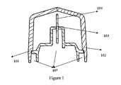
- FIG.1 shows a classic LED lamp in prior art, wherein red lampshade 101 and clear lampshade 102 are provided for light distributing. Both components are produced by injection molding, and the two components are connected by ultra-sonic welding.
- a pluggable cavity 103 is provided on the enclosure, and a PCB 104 is inserted into the pluggable cavity 103 for securing.
- the LED Lamp mentioned above has the following defects,
- the ultra-sonic welding needs additional cost (for welding equipment, etc). Meanwhile, failure rate of seal structures and appearance for the welded light distributing lampshade is higher than those for molded light distributing lampshade (Although failure rate of seal structures and appearance for the molded light distributing lampshade is lower than those for welded light distributing lampshade, the cost for double-color injection molding is higher however).
- PCB should be connected with enclosure first, then the cooperative relationship between LED and optical surface should be achieved by installation of enclosure and light distributing lampshade. It will lead to a cumulative tolerance, and a risk for optical effect. And much higher precision accuracies for enclosure, PCB and light distributing lampshade are required.
- the present invention provides a LED lamp without double-color injection molding or welding.
- the red/clear light distributing lampshades and PCB including LED are installed directly, and the PCB is hold between red/clear light distributing lampshades without additional components.
- the LED lamp comprises an enclosure, a PCB provided in the enclosure, a first light distributing lampshade arranged in one side of the PCB and a second light distributing lampshade arranged in the other side of the PCB.
- the first light distributing lampshade is a red light distributing lampshade
- the second light distributing lampshade is a clear light distributing lampshade.
- a positioning hole is provided on the PCB and a positioning column which is fitted into the positioning hole is provided on the first light distributing lampshade and second light distributing lampshade.
- the PCB is held in position by engaging part formed on the first and second light distributing lampshades.
- the LED lamp further comprises a base plate, which, together with the said enclosure, defines an inner space for enclosing the PCB, first and second light distributing lampshades. And the enclosure has a catch; the base plate has a cooperating slot.
- seal gum is filled in the gap between the enclosure, PCB and/or first and second light distributing lampshades.
- the LED lamp has a connector
- the PCB has a pin for electrically connecting with the connector
- Enclosure- made for protecting light distributing components and PCB. And the enclosure has a catch so as to engage with the base plate.
- First and second light distributing lampshades - light distributing components.
- the light emitted by LED fit the light distribution requirement of position/ marker lamp.
- the first and second light distributing lampshades have positioning columns for the PCB's positioning hole.
- PCB- LED is provided on each of its two sides, and the PCB has a pin for electrically connecting with lamp's connector.
- Base plate- made for connecting the LED lamp with car body.
- the base plate has a slot so as to be connected with the enclosure by plug-in connection.
- Connector- made for electrically connecting with car body.
- the present invention has the following technical effects,
- the light distributing components and PCB including LED are installed directly without additional components (such as enclosure) so as to reduce cumulative tolerance during assembly procedure.
- FIG. 1 is a structural schematic view of a LED lamp in prior art
- FIG. 2 is a sectional view of a LED lamp without base plate and connector in present application
- FIG. 3 is a sectional view of a LED lamp without base plate and connector in present application
- FIG. 4 is an inner structural schematic view of a LED lamp without base plate and connector in present application
- FIG. 5 is a schematic view of a LED lamp with base plate and connector in present application.
- FIG. 2-4 With reference to FIG. 2-4 , a particularly preferred embodiment of the invention with simpler structure is illustrated.
- the LED lamp of the present application includes an enclosure 1, a PCB 4 provided in the enclosure 1, a first light distributing lampshade 2 arranged in one side of the PCB 4 and a second light distributing lampshade 3 arranged in the other side of the PCB 4.
- the first light distributing lampshade 2 is a red light distributing lampshade
- the second light distributing lampshade 3 is a clear light distributing lampshade.
- FIG. 2 is a sectional view of a LED lamp without base plate and connector.
- a positioning hole is provided on the PCB 4 and positioning columns 11a, 11b which are fitted into the positioning hole is provided on the first light distributing lampshade 2 and second light distributing lampshade 3.
- the positioning columns 11a, 11b and the positioning hole are arranged staggered shown in FIG. 2 so as to hold the PCB 4 in position.
- FIG. 3 is a sectional view of a LED lamp without base plate and connector.
- the PCB 4 is held in position by engaging parts 13 formed on first and second light distributing lampshades 2, 3 for clamping the PCB 4.
- the PCB 4 and light distributing components are installed together by the above positioning columns 11a, 11b and engaging part structure.
- extension parts 8 are formed in first and second light distributing lampshades2, 3, and depression parts 9 are formed in enclosure 1 so as to engage with the extension parts 8.
- invert the whole as shown in FIG. 4 the PCB 4 is held in position between the first and second light distributing lampshades 2, 3.
- the enclosure 1 has catches 12 for engaging with the base plate 6.
- the PCB 4 has a pin 10 for electrically connecting with car body.
- the base plate 6 and the enclosure 1 are installed together by the catches 12.
- the connector 7 is connected together with the PCB 4 through the pin 10.
- seal gum is filled in the gap 5 (shown in FIG. 2, FIG. 3 ) between the enclosure 1, PCB 4 and/or first and second light distributing lampshades2, 3 for firmly sealing the LED lamp.
- the base plate 6 and the enclosure 1 are installed together by the catches 12 so as to form the complete lamp.
- the LED lamp of the present application is installed without double-color injection molding or welding so as to reduce cost. And the light distributing components and PCB including LED are installed directly without additional components (such as enclosure) so as to reduce tolerance accumulation during assembly procedure.
Landscapes
- Engineering & Computer Science (AREA)
- Mechanical Engineering (AREA)
- General Engineering & Computer Science (AREA)
- Physics & Mathematics (AREA)
- Microelectronics & Electronic Packaging (AREA)
- Optics & Photonics (AREA)
- Non-Portable Lighting Devices Or Systems Thereof (AREA)
- Fastening Of Light Sources Or Lamp Holders (AREA)
Abstract
A LED lamp, comprising an enclosure (1), a PCB (4) provided in the enclosure (1), a first light distributing lampshade (2) arranged in one side of the PCB (4) and a second light distributing lampshade (3) arranged in the other side of the PCB (4), wherein a positioning hole is provided on the PCB and a positioning column (11a,11b) which is fitted into the positioning hole is provided on the first light distributing lampshade (2) and second light distributing lampshade (3).
Description
- The present invention relates to LED Lamp.
- The types of LED lamp include position lamp, marker lamp and other functionally similar lamps. The position/ marker lamp needs to emit red light and white light at the same time, and meanwhile integration of the position/ marker lamp should be considered. In prior art, there are two different solutions,
- 1. Connect red/ clear light distributing lampshades together by double-color injection molding or welding, and then a PCB including LED is secured on the enclosure. And the enclosure and light distributing lampshades are sealed together. LED should fit optical surface.
- 2. Prepare red/ clear light distributing components, and the components and a PCB are secured on the enclosure. LED should fit optical surface. And then the enclosure and light distributing lampshades are sealed together to form the complete lamp.
-
FIG.1 shows a classic LED lamp in prior art, whereinred lampshade 101 andclear lampshade 102 are provided for light distributing. Both components are produced by injection molding, and the two components are connected by ultra-sonic welding. - A
pluggable cavity 103 is provided on the enclosure, and aPCB 104 is inserted into thepluggable cavity 103 for securing. - Connect the above mentioned enclosure with the light distributing lampshades by filing seal gum in the
area 105 so as to form the complete lamp. - The LED Lamp mentioned above has the following defects,
- 1. The ultra-sonic welding needs additional cost (for welding equipment, etc). Meanwhile, failure rate of seal structures and appearance for the welded light distributing lampshade is higher than those for molded light distributing lampshade (Although failure rate of seal structures and appearance for the molded light distributing lampshade is lower than those for welded light distributing lampshade, the cost for double-color injection molding is higher however).
- 2. PCB should be connected with enclosure first, then the cooperative relationship between LED and optical surface should be achieved by installation of enclosure and light distributing lampshade. It will lead to a cumulative tolerance, and a risk for optical effect. And much higher precision accuracies for enclosure, PCB and light distributing lampshade are required.
- There is a need for a LED lamp with simpler structure and higher precision accuracies
- The present invention provides a LED lamp without double-color injection molding or welding. The red/clear light distributing lampshades and PCB including LED are installed directly, and the PCB is hold between red/clear light distributing lampshades without additional components.
- The LED lamp comprises an enclosure, a PCB provided in the enclosure, a first light distributing lampshade arranged in one side of the PCB and a second light distributing lampshade arranged in the other side of the PCB. Preferably, the first light distributing lampshade is a red light distributing lampshade; the second light distributing lampshade is a clear light distributing lampshade.
- Wherein, a positioning hole is provided on the PCB and a positioning column which is fitted into the positioning hole is provided on the first light distributing lampshade and second light distributing lampshade.
- Wherein, the PCB is held in position by engaging part formed on the first and second light distributing lampshades.
- Wherein, the LED lamp further comprises a base plate, which, together with the said enclosure, defines an inner space for enclosing the PCB, first and second light distributing lampshades. And the enclosure has a catch; the base plate has a cooperating slot.
- Wherein, seal gum is filled in the gap between the enclosure, PCB and/or first and second light distributing lampshades.
- Wherein, the LED lamp has a connector, and the PCB has a pin for electrically connecting with the connector.
- The above components have the following functions,
- Enclosure- made for protecting light distributing components and PCB. And the enclosure has a catch so as to engage with the base plate.
- First and second light distributing lampshades - light distributing components. Through the light distributing lampshades, the light emitted by LED fit the light distribution requirement of position/ marker lamp. In addition, the first and second light distributing lampshades have positioning columns for the PCB's positioning hole.
- PCB- LED is provided on each of its two sides, and the PCB has a pin for electrically connecting with lamp's connector.
- Base plate- made for connecting the LED lamp with car body. The base plate has a slot so as to be connected with the enclosure by plug-in connection.
- Connector- made for electrically connecting with car body.
- The present invention has the following technical effects,
- 1. Reducing cost. No additional double-color injection molding or welding equipments are required.
- 2. Reducing a cumulative tolerance. The light distributing components and PCB including LED are installed directly without additional components (such as enclosure) so as to reduce cumulative tolerance during assembly procedure.
-
FIG. 1 is a structural schematic view of a LED lamp in prior art; -
FIG. 2 is a sectional view of a LED lamp without base plate and connector in present application; -
FIG. 3 is a sectional view of a LED lamp without base plate and connector in present application; -
FIG. 4 is an inner structural schematic view of a LED lamp without base plate and connector in present application; -
FIG. 5 is a schematic view of a LED lamp with base plate and connector in present application. - The application will be described below in more detail with reference to figures and embodiments.
- With reference to
FIG. 2-4 , a particularly preferred embodiment of the invention with simpler structure is illustrated. - The LED lamp of the present application includes an
enclosure 1, a PCB 4 provided in theenclosure 1, a firstlight distributing lampshade 2 arranged in one side of the PCB 4 and a secondlight distributing lampshade 3 arranged in the other side of the PCB 4. Preferably, the firstlight distributing lampshade 2 is a red light distributing lampshade; the secondlight distributing lampshade 3 is a clear light distributing lampshade. -
FIG. 2 is a sectional view of a LED lamp without base plate and connector. With reference toFIG. 2 , a positioning hole is provided on the PCB 4 andpositioning columns light distributing lampshade 2 and secondlight distributing lampshade 3. When theabove positioning columns positioning columns FIG. 2 so as to hold the PCB 4 in position. -
FIG. 3 is a sectional view of a LED lamp without base plate and connector. With reference toFIG. 3 , the PCB 4 is held in position by engagingparts 13 formed on first and secondlight distributing lampshades - The PCB 4 and light distributing components are installed together by the
above positioning columns - After the PCB 4 and first and second
light distributing lampshades enclosure 1. With reference toFIG. 2 ,extension parts 8 are formed in first and second light distributing lampshades2, 3, and depression parts 9 are formed inenclosure 1 so as to engage with theextension parts 8. After the above installation, invert the whole as shown inFIG. 4 . With reference toFIG. 4 , the PCB 4 is held in position between the first and secondlight distributing lampshades enclosure 1 hascatches 12 for engaging with the base plate 6. The PCB 4 has apin 10 for electrically connecting with car body. - With reference to
FIG. 4 , the base plate 6 and theenclosure 1 are installed together by thecatches 12. The connector 7 is connected together with the PCB 4 through thepin 10. Then, seal gum is filled in the gap 5 (shown inFIG. 2, FIG. 3 ) between theenclosure 1, PCB 4 and/or first and second light distributing lampshades2, 3 for firmly sealing the LED lamp. After the sealing process, the base plate 6 and theenclosure 1 are installed together by thecatches 12 so as to form the complete lamp. - Different with the prior art, the LED lamp of the present application is installed without double-color injection molding or welding so as to reduce cost. And the light distributing components and PCB including LED are installed directly without additional components (such as enclosure) so as to reduce tolerance accumulation during assembly procedure.
- It should be appreciated, however, that the embodiments provide many applicable inventive concepts that can be embodied in a wide variety of specific contexts. The specific embodiments discussed are merely illustrative, and do not limit the scope of the disclosure.
Claims (8)
- A LED lamp, comprising an enclosure, a PCB provided in said enclosure, a first light distributing lampshade arranged in one side of said PCB and a second light distributing lampshade arranged in the other side of said PCB, wherein a positioning hole is provided on said PCB and a positioning column which is fitted into said positioning hole is provided on said first light distributing lampshade and second light distributing lampshade.
- LED lamp according to Claim 1, wherein said PCB is held in position by engaging part formed on said first and second light distributing lampshades.
- LED lamp according to Claim 1, wherein further comprises a base plate, which, together with said enclosure, defines an inner space for enclosing said PCB, first and second light distributing lampshades.
- LED lamp according to Claim 3, wherein said enclosure has a catch, and said base plate has a cooperating slot.
- LED lamp according to Claim 3, wherein seal gum is filled in the gap between said enclosure, PCB and/or first and second light distributing lampshades.
- LED lamp according to Claim 1, wherein said LED lamp has a connector, and said PCB has a pin for electrically connecting with said connector.
- LED lamp according to Claim 1, wherein said first light distributing lampshade is a red light distributing lampshade, and said second light distributing lampshade is a clear light distributing lampshade.
- LED lamp according to Claim 1, wherein, when said positioning column is inserted into said positioning hole, said positioning column and said positioning hole is arranged staggered.
Applications Claiming Priority (1)
| Application Number | Priority Date | Filing Date | Title |
|---|---|---|---|
| CN2012205819364U CN202972854U (en) | 2012-11-07 | 2012-11-07 | LED (Light Emitting Diode) car lamp |
Publications (1)
| Publication Number | Publication Date |
|---|---|
| EP2730462A1 true EP2730462A1 (en) | 2014-05-14 |
Family
ID=48513924
Family Applications (1)
| Application Number | Title | Priority Date | Filing Date |
|---|---|---|---|
| EP13191538.1A Withdrawn EP2730462A1 (en) | 2012-11-07 | 2013-11-05 | LED Lamp |
Country Status (2)
| Country | Link |
|---|---|
| EP (1) | EP2730462A1 (en) |
| CN (1) | CN202972854U (en) |
Families Citing this family (1)
| Publication number | Priority date | Publication date | Assignee | Title |
|---|---|---|---|---|
| CN113776025A (en) * | 2021-09-14 | 2021-12-10 | 沈阳道达汽车饰件有限公司 | A kind of vehicle lamp sealing structure and sealing method |
Citations (8)
| Publication number | Priority date | Publication date | Assignee | Title |
|---|---|---|---|---|
| FR2639683A1 (en) * | 1988-11-28 | 1990-06-01 | Autorupteur Cie Nle | Light projector |
| JPH0545811U (en) * | 1991-11-15 | 1993-06-18 | 株式会社小糸製作所 | Vehicle marker light |
| JPH08268152A (en) * | 1995-03-30 | 1996-10-15 | Koito Mfg Co Ltd | Fender marker |
| US6280480B1 (en) * | 1998-10-30 | 2001-08-28 | Meridian Automotive Systems, Inc. | Indirect illumination taillamp assembly for a vehicle |
| EP1510457A2 (en) * | 2004-10-11 | 2005-03-02 | Flight Components AG | Anti collision light for aircraft |
| DE102005004050A1 (en) * | 2005-01-28 | 2006-08-10 | Johann & Konen Gmbh & Co. Kg | Light especially for a motor vehicle, has base with receiver for the lamp and a transparent hood fixed to the base by invisible internal connectors |
| EP2186680A1 (en) * | 2008-11-14 | 2010-05-19 | Hella KG Hueck & Co. | Light for vehicles |
| DE102010043313A1 (en) * | 2010-11-03 | 2012-05-03 | Hella Kgaa Hueck & Co. | Illumination device for vehicle, has several positioning elements that are formed in preset reflector and circuit board for assembling reflectors and circuit board into assembly position using separate fasteners |
-
2012
- 2012-11-07 CN CN2012205819364U patent/CN202972854U/en not_active Expired - Lifetime
-
2013
- 2013-11-05 EP EP13191538.1A patent/EP2730462A1/en not_active Withdrawn
Patent Citations (8)
| Publication number | Priority date | Publication date | Assignee | Title |
|---|---|---|---|---|
| FR2639683A1 (en) * | 1988-11-28 | 1990-06-01 | Autorupteur Cie Nle | Light projector |
| JPH0545811U (en) * | 1991-11-15 | 1993-06-18 | 株式会社小糸製作所 | Vehicle marker light |
| JPH08268152A (en) * | 1995-03-30 | 1996-10-15 | Koito Mfg Co Ltd | Fender marker |
| US6280480B1 (en) * | 1998-10-30 | 2001-08-28 | Meridian Automotive Systems, Inc. | Indirect illumination taillamp assembly for a vehicle |
| EP1510457A2 (en) * | 2004-10-11 | 2005-03-02 | Flight Components AG | Anti collision light for aircraft |
| DE102005004050A1 (en) * | 2005-01-28 | 2006-08-10 | Johann & Konen Gmbh & Co. Kg | Light especially for a motor vehicle, has base with receiver for the lamp and a transparent hood fixed to the base by invisible internal connectors |
| EP2186680A1 (en) * | 2008-11-14 | 2010-05-19 | Hella KG Hueck & Co. | Light for vehicles |
| DE102010043313A1 (en) * | 2010-11-03 | 2012-05-03 | Hella Kgaa Hueck & Co. | Illumination device for vehicle, has several positioning elements that are formed in preset reflector and circuit board for assembling reflectors and circuit board into assembly position using separate fasteners |
Also Published As
| Publication number | Publication date |
|---|---|
| CN202972854U (en) | 2013-06-05 |
Similar Documents
| Publication | Publication Date | Title |
|---|---|---|
| US11223158B2 (en) | Waterproof electronic component and method for assembling the same | |
| JPWO2016158423A1 (en) | Light source unit and vehicle lamp | |
| CN102644862A (en) | Lamp tube structure and assembly thereof | |
| US20140199870A1 (en) | Structure of highly waterproof connector for easy conduction between ground pin and body | |
| CN102740646B (en) | A kind of installation method of power device and installation component | |
| CN111853572A (en) | A waterproof strip light | |
| CN104197262A (en) | LED automobile lamp, manufacturing method of LED automobile lamp and automobile headlamp assembly | |
| WO2014131340A1 (en) | Electronic expansion valve and connection assembly therefor | |
| CN102829455B (en) | Connector assembly for connecting power supply plate and light source plate in LED (Light Emitting Diode) bulb and method | |
| WO2010020497A1 (en) | Lighting device | |
| CA2728372C (en) | Connector terminal for lamps | |
| CN104218356B (en) | Photoelectric Mixed Connector | |
| CN104110589B (en) | Display lamp and luminescent device thereof | |
| CN203786332U (en) | Optical fiber rapid connector with reliable assembling and automatic butt joint | |
| CN207455221U (en) | Photoelectricity module with connector and the LEDbulb lamp using the photoelectricity module | |
| CN202972854U (en) | LED (Light Emitting Diode) car lamp | |
| CN212361688U (en) | LED module | |
| CN205640477U (en) | Waterproof LED frame lamp | |
| CN104033865B (en) | Socket lamp body | |
| CN207796931U (en) | A kind of mounting structure improving positional precision between lamp guide and LED brackets | |
| CN104602960B (en) | Screw connection in headlamp | |
| CN203024092U (en) | LED (Light Emitting Diode) lamp bar mounting assembly | |
| CN206697640U (en) | Automobile using power supply connector and automobile circuit erecting device | |
| CN206790759U (en) | Black appliances fill stabilizer | |
| CN207796927U (en) | A kind of mounting structure reducing interior len and substrate with deviation of light |
Legal Events
| Date | Code | Title | Description |
|---|---|---|---|
| PUAI | Public reference made under article 153(3) epc to a published international application that has entered the european phase |
Free format text: ORIGINAL CODE: 0009012 |
|
| 17P | Request for examination filed |
Effective date: 20131105 |
|
| AK | Designated contracting states |
Kind code of ref document: A1 Designated state(s): AL AT BE BG CH CY CZ DE DK EE ES FI FR GB GR HR HU IE IS IT LI LT LU LV MC MK MT NL NO PL PT RO RS SE SI SK SM TR |
|
| AX | Request for extension of the european patent |
Extension state: BA ME |
|
| RAP1 | Party data changed (applicant data changed or rights of an application transferred) |
Owner name: HELLA GMBH & CO. KGAA |
|
| STAA | Information on the status of an ep patent application or granted ep patent |
Free format text: STATUS: THE APPLICATION IS DEEMED TO BE WITHDRAWN |
|
| 18D | Application deemed to be withdrawn |
Effective date: 20141115 |