EP2730398B1 - Apparatus for molding core of vacuum insulation panel and vacuum insulation panel manufactured thereby - Google Patents
Apparatus for molding core of vacuum insulation panel and vacuum insulation panel manufactured thereby Download PDFInfo
- Publication number
- EP2730398B1 EP2730398B1 EP13192008.4A EP13192008A EP2730398B1 EP 2730398 B1 EP2730398 B1 EP 2730398B1 EP 13192008 A EP13192008 A EP 13192008A EP 2730398 B1 EP2730398 B1 EP 2730398B1
- Authority
- EP
- European Patent Office
- Prior art keywords
- molding
- core
- molding plate
- exhaust cavity
- insulation panel
- Prior art date
- Legal status (The legal status is an assumption and is not a legal conclusion. Google has not performed a legal analysis and makes no representation as to the accuracy of the status listed.)
- Active
Links
Images



Classifications
-
- B—PERFORMING OPERATIONS; TRANSPORTING
- B29—WORKING OF PLASTICS; WORKING OF SUBSTANCES IN A PLASTIC STATE IN GENERAL
- B29C—SHAPING OR JOINING OF PLASTICS; SHAPING OF MATERIAL IN A PLASTIC STATE, NOT OTHERWISE PROVIDED FOR; AFTER-TREATMENT OF THE SHAPED PRODUCTS, e.g. REPAIRING
- B29C43/00—Compression moulding, i.e. applying external pressure to flow the moulding material; Apparatus therefor
- B29C43/02—Compression moulding, i.e. applying external pressure to flow the moulding material; Apparatus therefor of articles of definite length, i.e. discrete articles
-
- B—PERFORMING OPERATIONS; TRANSPORTING
- B30—PRESSES
- B30B—PRESSES IN GENERAL
- B30B9/00—Presses specially adapted for particular purposes
- B30B9/30—Presses specially adapted for particular purposes for baling; Compression boxes therefor
- B30B9/3075—Presses specially adapted for particular purposes for baling; Compression boxes therefor with press boxes on a movable carrier, e.g. turntable
-
- B—PERFORMING OPERATIONS; TRANSPORTING
- B29—WORKING OF PLASTICS; WORKING OF SUBSTANCES IN A PLASTIC STATE IN GENERAL
- B29C—SHAPING OR JOINING OF PLASTICS; SHAPING OF MATERIAL IN A PLASTIC STATE, NOT OTHERWISE PROVIDED FOR; AFTER-TREATMENT OF THE SHAPED PRODUCTS, e.g. REPAIRING
- B29C41/00—Shaping by coating a mould, core or other substrate, i.e. by depositing material and stripping-off the shaped article; Apparatus therefor
- B29C41/02—Shaping by coating a mould, core or other substrate, i.e. by depositing material and stripping-off the shaped article; Apparatus therefor for making articles of definite length, i.e. discrete articles
-
- B—PERFORMING OPERATIONS; TRANSPORTING
- B29—WORKING OF PLASTICS; WORKING OF SUBSTANCES IN A PLASTIC STATE IN GENERAL
- B29C—SHAPING OR JOINING OF PLASTICS; SHAPING OF MATERIAL IN A PLASTIC STATE, NOT OTHERWISE PROVIDED FOR; AFTER-TREATMENT OF THE SHAPED PRODUCTS, e.g. REPAIRING
- B29C59/00—Surface shaping of articles, e.g. embossing; Apparatus therefor
- B29C59/02—Surface shaping of articles, e.g. embossing; Apparatus therefor by mechanical means, e.g. pressing
- B29C59/022—Surface shaping of articles, e.g. embossing; Apparatus therefor by mechanical means, e.g. pressing characterised by the disposition or the configuration, e.g. dimensions, of the embossments or the shaping tools therefor
-
- B—PERFORMING OPERATIONS; TRANSPORTING
- B29—WORKING OF PLASTICS; WORKING OF SUBSTANCES IN A PLASTIC STATE IN GENERAL
- B29D—PRODUCING PARTICULAR ARTICLES FROM PLASTICS OR FROM SUBSTANCES IN A PLASTIC STATE
- B29D99/00—Subject matter not provided for in other groups of this subclass
- B29D99/001—Producing wall or panel-like structures, e.g. for hulls, fuselages, or buildings
- B29D99/0021—Producing wall or panel-like structures, e.g. for hulls, fuselages, or buildings provided with plain or filled structures, e.g. cores, placed between two or more plates or sheets, e.g. in a matrix
-
- B—PERFORMING OPERATIONS; TRANSPORTING
- B30—PRESSES
- B30B—PRESSES IN GENERAL
- B30B11/00—Presses specially adapted for forming shaped articles from material in particulate or plastic state, e.g. briquetting presses, tabletting presses
-
- B—PERFORMING OPERATIONS; TRANSPORTING
- B30—PRESSES
- B30B—PRESSES IN GENERAL
- B30B11/00—Presses specially adapted for forming shaped articles from material in particulate or plastic state, e.g. briquetting presses, tabletting presses
- B30B11/02—Presses specially adapted for forming shaped articles from material in particulate or plastic state, e.g. briquetting presses, tabletting presses using a ram exerting pressure on the material in a moulding space
- B30B11/04—Presses specially adapted for forming shaped articles from material in particulate or plastic state, e.g. briquetting presses, tabletting presses using a ram exerting pressure on the material in a moulding space co-operating with a fixed mould
-
- B—PERFORMING OPERATIONS; TRANSPORTING
- B30—PRESSES
- B30B—PRESSES IN GENERAL
- B30B11/00—Presses specially adapted for forming shaped articles from material in particulate or plastic state, e.g. briquetting presses, tabletting presses
- B30B11/02—Presses specially adapted for forming shaped articles from material in particulate or plastic state, e.g. briquetting presses, tabletting presses using a ram exerting pressure on the material in a moulding space
- B30B11/14—Presses specially adapted for forming shaped articles from material in particulate or plastic state, e.g. briquetting presses, tabletting presses using a ram exerting pressure on the material in a moulding space co-operating with moulds on a movable carrier other than a turntable or a rotating drum
-
- B—PERFORMING OPERATIONS; TRANSPORTING
- B30—PRESSES
- B30B—PRESSES IN GENERAL
- B30B15/00—Details of, or accessories for, presses; Auxiliary measures in connection with pressing
- B30B15/0005—Details of, or accessories for, presses; Auxiliary measures in connection with pressing for briquetting presses
- B30B15/0017—Deairing means
-
- B—PERFORMING OPERATIONS; TRANSPORTING
- B30—PRESSES
- B30B—PRESSES IN GENERAL
- B30B15/00—Details of, or accessories for, presses; Auxiliary measures in connection with pressing
- B30B15/06—Platens or press rams
- B30B15/062—Press plates
-
- B—PERFORMING OPERATIONS; TRANSPORTING
- B30—PRESSES
- B30B—PRESSES IN GENERAL
- B30B15/00—Details of, or accessories for, presses; Auxiliary measures in connection with pressing
- B30B15/30—Feeding material to presses
- B30B15/302—Feeding material in particulate or plastic state to moulding presses
-
- B—PERFORMING OPERATIONS; TRANSPORTING
- B30—PRESSES
- B30B—PRESSES IN GENERAL
- B30B9/00—Presses specially adapted for particular purposes
- B30B9/30—Presses specially adapted for particular purposes for baling; Compression boxes therefor
- B30B9/3085—Presses specially adapted for particular purposes for baling; Compression boxes therefor using a stationary press ram co-operating with a movable press box
-
- B—PERFORMING OPERATIONS; TRANSPORTING
- B30—PRESSES
- B30B—PRESSES IN GENERAL
- B30B9/00—Presses specially adapted for particular purposes
- B30B9/30—Presses specially adapted for particular purposes for baling; Compression boxes therefor
- B30B9/3096—Presses specially adapted for particular purposes for baling; Compression boxes therefor the means against which, or wherein, the material is compacted being retractable
-
- F—MECHANICAL ENGINEERING; LIGHTING; HEATING; WEAPONS; BLASTING
- F16—ENGINEERING ELEMENTS AND UNITS; GENERAL MEASURES FOR PRODUCING AND MAINTAINING EFFECTIVE FUNCTIONING OF MACHINES OR INSTALLATIONS; THERMAL INSULATION IN GENERAL
- F16L—PIPES; JOINTS OR FITTINGS FOR PIPES; SUPPORTS FOR PIPES, CABLES OR PROTECTIVE TUBING; MEANS FOR THERMAL INSULATION IN GENERAL
- F16L59/00—Thermal insulation in general
- F16L59/06—Arrangements using an air layer or vacuum
- F16L59/065—Arrangements using an air layer or vacuum using vacuum
-
- Y—GENERAL TAGGING OF NEW TECHNOLOGICAL DEVELOPMENTS; GENERAL TAGGING OF CROSS-SECTIONAL TECHNOLOGIES SPANNING OVER SEVERAL SECTIONS OF THE IPC; TECHNICAL SUBJECTS COVERED BY FORMER USPC CROSS-REFERENCE ART COLLECTIONS [XRACs] AND DIGESTS
- Y10—TECHNICAL SUBJECTS COVERED BY FORMER USPC
- Y10T—TECHNICAL SUBJECTS COVERED BY FORMER US CLASSIFICATION
- Y10T428/00—Stock material or miscellaneous articles
- Y10T428/24—Structurally defined web or sheet [e.g., overall dimension, etc.]
- Y10T428/24479—Structurally defined web or sheet [e.g., overall dimension, etc.] including variation in thickness
-
- Y—GENERAL TAGGING OF NEW TECHNOLOGICAL DEVELOPMENTS; GENERAL TAGGING OF CROSS-SECTIONAL TECHNOLOGIES SPANNING OVER SEVERAL SECTIONS OF THE IPC; TECHNICAL SUBJECTS COVERED BY FORMER USPC CROSS-REFERENCE ART COLLECTIONS [XRACs] AND DIGESTS
- Y10—TECHNICAL SUBJECTS COVERED BY FORMER USPC
- Y10T—TECHNICAL SUBJECTS COVERED BY FORMER US CLASSIFICATION
- Y10T428/00—Stock material or miscellaneous articles
- Y10T428/24—Structurally defined web or sheet [e.g., overall dimension, etc.]
- Y10T428/24479—Structurally defined web or sheet [e.g., overall dimension, etc.] including variation in thickness
- Y10T428/24612—Composite web or sheet
Definitions
- the following description relates to an apparatus for molding a core of a vacuum insulation panel according to claim 1.
- Insulation panels are used to limit transference of heat in buildings, pipes, and ice boxes where there is temperature difference between the interior and exterior thereof
- General insulation panels or vacuum insulation panels are mostly used for the above purpose.
- a general insulation panel refers to an insulation panel having an insulation performance of 30mW/mK, whereas a vacuum insulation panel is an insulation panel having a high insulation performance of 3 ⁇ mW/mK.
- a vacuum insulation panel is an insulation panel having a high insulation performance of 3 ⁇ mW/mK.
- a vacuum insulation panel consists of a molded insulation body made of inorganic substances and a gas insulation film covering the molded insulation body.
- the biggest feature of a vacuum insulation panel is that the interior of the molded insulation body is prepared in a vacuum condition.
- the molded insulation body that fills the inside of the vacuum insulation panel is called a core.
- One way to manufacture a core is to use a glass fiber compressed material or mixed powder including silica.
- KR 20120028048 discloses the method of pressing mixed powder that includes fumed silica in a molding cast through a continuously revolving molding cast, and thus shows enhanced mechanical strength, and is capable of molding a core of which the exterior has a rectangular shape with reduced molding time.
- US 4564547 , US 2026940 , GB 2284172 and EP1098104 describe apparatus for manufacturing blocks by compacting granular material in a mold by means of a pressing tool.
- felt was installed on the exterior of the molding plate so as to prevent direct contact between the molding plate and mixed powder, but when used for more than a certain number of times, the felt is damaged and thus affects the molding of the core or the apparatus must be stopped to replace the felt, thereby delaying the process time and reducing the productivity.
- a manufactured core is used as a vacuum insulation panel through a packaging process where it is accommodated in a packaging material of which the interior is kept in a vacuum condition, which prevents external elements from coming inside the core, thereby increasing the durability of the vacuum insulation panel.
- the packaging process may be performed by accommodating the core inside the packaging material, and then discharging the air inside the packaging material outside through a vacuum pump etc.
- the problem of the aforementioned packaging process is that the vacuum inside the vacuum insulation panel acts as a limitation to improvement, generates creases on the surface of the vacuum insulation panel, and creates leakage between the wall and the surface of the vacuum insulating panel when attaching the vacuum insulation panel to the wall, reducing the insulating effect.
- a purpose of the present disclosure is to resolve the aforementioned problems of prior art, that is, to provide an apparatus for molding a core of a vacuum insulation panel capable of easily discharging from the molding space residue that may have negative effects on core molding.
- Another purpose of the present disclosure is to provide an apparatus for molding a core of a vacuum insulation panel capable of efficiently discharging air inside the packaging material when packaging the core by forming a pattern on an exterior surface of the core at the same time as molding the core, and a vacuum insulation panel manufactured thereby.
- an apparatus for molding a core of a vacuum insulation panel comprising: a pair of molding plates distanced from and facing each other to form a molding space where a core is molded; a molding cast configured to close the molding space from outside; and a pressing member configured to press at least one of the pair of molding plates; wherein the at least one of the pair of molding plates comprises: a pattern portion which is provided on a first surface facing the molding space, and which transcribes a pattern on an exterior surface of the core; and an exhaust cavity penetrating the molding plate in a thickness direction from the first surface to a second surface opposite the first surface.
- the pair of molding plates comprises: a first molding plate that is provided on an upper side of the molding space to open and close the molding cast; and a second molding plate that is provided on a lower side of the molding space.
- the second molding plate which moves in the molding space, has the first surface having a bigger cross-sectional area than a cross-sectional area of the second surface in such a manner that the distance between the molding cast and the second molding plate becomes wider in a direction away from the molding space.
- the cross-sectional area of the exhaust cavity of a second surface may be bigger than that of the first surface.
- the pattern portion may be provided with repeatedly arranged protrusions that protrude from the first surface and repeatedly arranged recesses that recess towards the inside of the first surface.
- the height of the protrusion may be 0.02 mm to 0.5mm.
- the molding plate may comprise a coating member.
- the diameter of the exhaust cavity on the first surface may be 0.2 mm to 3mm.
- the diameter of the exhaust cavity on the second surface may be 2 mm to 10mm.
- the exhaust cavity may comprise an increase section where the closer to the second surface from the first surface, the bigger the diameter thereof, and a maintain section where the diameter thereof is maintained to be the same.
- the number of exhaust cavity formed per unit of 1m 2 of the molding plate may be 650 to 3300 or 1200 to 1800.
- the molding cast may have a bigger bottom surface that faces the second molding plate than the second molding plate.
- an apparatus for molding a core of a vacuum insulation panel that may easily discharge residue that are attached to the exterior surface of the molding plate and have negative effects when molding the core, and a vacuum insulation panel manufactured thereby.
- the diameter of an exhaust cavity of the molding plate may be formed in such a manner that the farther away from the core, the bigger the diameter of the exhaust cavity of the molding plate, thereby preventing the core material being stuck in the exhaust cavity and the exhaust cavity being blocked.
- the powder provided in the molding space through the coating member contact the molding plate, it is possible to prevent the powder from being attached to the molding plate.
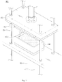
- FIG. 1 is a schematic skewed view of an apparatus for molding a core of a vacuum insulating panel according to an exemplary embodiment of the present disclosure
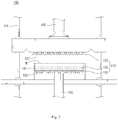
- FIG. 2 is a schematic cross-sectional view of an apparatus for molding a core of a vacuum insulating panel according to FIG. 1 .
- the apparatus for molding a core of a vacuum insulation panel according to an exemplary embodiment of the present disclosure 100 may form a specific pattern on a surface of the core at the same time of molding the core, and may easily discharge from the molding space the air inside the core material that forms the core and the floating particles that may be generated in the molding process.
- the apparatus for molding a core of a vacuum insulation panel 100 comprises a molding plate 110, molding cast 140, and a pressing member 150.
- the molding plate 110 is provided as a pair of plate members that face each other and are distanced from each other, forming a molding space M that is a space between the pair of molding plates 110.
- the molding plate 110 presses and compresses the core material provided inside the molding space M, and in the exemplary embodiment of the present disclosure, the pair of molding plates 110 comprises a first molding plate 120 disposed on the upper side and a second molding plate 130 disposed on the lower side, the two molding plates 120, 130 facing each other in the gravity direction.
- FIG. 3 is a schematic bottom view illustrating a first molding plate in an apparatus for molding a core of a vacuum insulation panel according to FIG. 1 .
- the first molding plate 120 presses the molding space M from the upper side.
- a pattern portion 121 is formed so that the core material is pressed and molded at the same time a pattern is formed, and an exhaust cavity 122 is formed that penetrates the first surface 120a and a second surface 120b(see FIG. 5 )
- the pattern portion 121 is provided in a particular pattern on the first surface 120a of the molding plate 120 such that a same shape is transcript on an exterior surface of the core 105 when molding the core 105.
- the pattern portion 121 is provided in a predetermined shape according to the manufacturer's intentions.
- a particular shape may be repeatedly formed such that the overall shape has the predetermined shape.
- the pattern portion 121 may be utilized as a flow path of air when packaging the core 150 molded according to the exemplary embodiment of the present disclosure with the packaging material and thus may improve the degree of vacuum.
- the pattern portion 121 may comprise as a protrusion 121a that is protruded towards the outside of the first surface 120a and a recess 121b that is recessed towards the inside of the first surface 120a.
- the pattern portion 121 may facilitate the air flow, and may reduce the power consumption of a vacuum pump and vacuum pumping time necessary to have the interior of the packaging material in a vacuum condition.
- the height of the protrusion 121a or the depth of the recess 121b may be 0.02mm to 0.5mm.
- the exhaust cavity 122 is a path that may discharge the air inside the molding space M during a molding process.
- the exhaust cavity 122 penetrates the first molding plate 120.
- the exhaust cavity 122b(see FIG. 5 ) of the second surface 120b side is bigger than the exhaust cavity 122a(see FIG. 5 ) of the first surface 120a side.
- the abovementioned function is one of the basic principles of fluid mechanics that can be explained by the Bernoulli's Theorem that the physicist Bernoulli announced in 1738.
- P represents the pressure of the fluid at a particular point
- p represents the density of the fluid
- v represents the velocity at a particular point
- g represents the acceleration of gravity
- h represents the height at a particular point.
- Q represents the discharge amount
- A represents the cross sectional area that the fluid passes
- v represents the velocity of the fluid. That is, it can be seen that the velocity of the fluid and the cross sectional area that the fluid passes when flowing through a particular area are inversely proportional to each other.
- the cross-sectional size at the molding space M (A 0 ) is the greatest, followed by the cross-sectional size of the exhaust cavity 122a of the first surface 120a side (A 1 ), followed by the cross-sectional size of the exhaust cavity 122b of the second surface 120b side (A 2 ).
- the velocity of fluid passing the exhaust cavity 122a of the first surface 120a side is the fastest, followed by the velocity of fluid passing the exhaust cavity 122b of the second surface 120b side, followed by the velocity of fluid inside the molding space M.
- the kinetic energy of the fluid being discharged may act as energy source for pushing the residue out from the exhaust cavity 122, and since the kinetic energy is proportionate to the square of velocity, residue may be pushed out most actively from the exhaust cavity 122a of the first surface 120a side having the fastest fluid discharge velocity.
- the viscosity force of the fluid being discharged may act as the force for pushing out the residue attached to the exhaust cavity 122 from the exhaust cavity 122, and since the viscosity force is proportionate to velocity, residue may be pushed out most actively from the exhaust cavity 122a of the first surface 120a side having the fastest fluid discharge velocity.
- the fluid inside the molding space M may be discharged smoothly along the exhaust cavity 122 from the molding space M.
- the diameter of the exhaust cavity 122a of the first surface 120a may be between the range of 0.2mm to 3.0mm, and the diameter of the exhaust cavity 122b of the second surface 120b may be between the range of 2.0mm to 10.0mm as long as it is bigger than the exhaust cavity 122a of the first surface 120a.
- the diameter of the exhaust cavity 122a of the first surface 120a may be 1.5mm and the diameter of the exhaust cavity 122b of the second surface 120b may be 5.0mm.
- the diameter of the exhaust cavity 122a of the first surface 120a side and the diameter cavity 122b of the second surface 120b side may be determined in comprehensive consideration of the components of the core 105, and the pressure on the molding space M during the core 105 molding process.
- the exhaust cavity 122 may comprise an increase section where the closer to the second surface 120b side from the first surface 120a, the bigger the area of cross-section, and a maintain section where the area of cross-section is maintained to be the same.
- the exhaust cavity 122 may only comprise an increase section where the closer to the second surface 120b side from the first surface 120a the bigger the area of cross-section.
- the exhaust cavity 122 may be of any shape as long as the size of the exhaust cavity 122a of the first surface 120a side is smaller than the size of the exhaust cavity 122b of the second surface 120b side.
- the number of the exhaust cavity 122 may be adjusted such that the air of the molding space M may be discharged appropriately. 650 to 3300, and more desirably 1200 to 1800 exhaust cavity 122 may be provided per unit area 1m 2 of the molding plate 110 so as to prevent loss of pressure on the first molding plate 120 from the upper side while appropriately discharging the air of the molding space M.
- each exhaust cavity 122 may be distanced by a distance of 15mm to 40mm from one another and form a grid.
- the exhaust cavity 122 may discharge air of the molding space M during upward movement of the first molding plate 120 thereby reducing the resistance caused by the air and facilitating movement of the first molding plate 120.
- the exterior surface of the first molding plate 120 may be coated with a coating member(not illustrated).
- the coating member(not illustrated) may prevent residue including core material etc. from remaining on the first molding plate 120.
- the coating member(not illustrated) may prevent the core material from being attached to the surface of the first molding plate 120.
- the coating member(not illustrated) may be made of a fluoroplastic material.
- the coating member(not illustrated) of the first molding plate 120 is made of a fluoroplastic material having weak adhesion, and thus prevents the core from being damaged when the first molding plate 120 is distanced from the core 105.
- the coating member(not illustrated) of the first molding plate 120 is made of a fluoroplastic material having low friction coefficient and adhesion, and thus may prevent the core from being damaged when discharging the core 105.
- the coating member(not illustrated) it is possible to prevent residue from being attached on the molding plate 110 and to lower the friction coefficient between the core 105 and the molding plate 110 thereby preventing the core from being damaged when discharging the core.
- the second molding plate 130 is a molding plate that is provided on the lower side of the molding space M such that it faces the molding plate 120.
- the second molding plate 130 is practically the same as the aforementioned first molding plate 120 except that it is disposed on the lower side of the molding apparatus 100, and thus detailed explanation thereof is omitted.
- the cross-section area of the first surface 130a near the molding space M is bigger than the cross-section area of the second surface 130b. Accordingly, the farther away from the molding space M, the wider the distance between the second molding plate 130 and the molding cast 140.
- Such a shape performs practically the same function as the aforementioned exhaust cavity 122, thereby easily discharging the air inside the molding space M and residue including some of the core material and preventing them from being adhered between the second molding plate 130 and molding cast 140.
- the molding cast 140 is a cast for closing the molding space M from outside and for determining the shape of the core 105 when molding the core.
- the molding cast 140 in the exemplary embodiment of the present disclosure wraps around the side of the molding space M, and the upper surface and the lower surface are open to the exterior.
- the pressing member 150 presses the molding plate 110 to press the core material from the inside of the molding space M.
- the pressing member150 according to an exemplary embodiment of the present disclosure is a well known technology and thus detailed explanation is omitted.
- the pressing member 150 is provided to apply preferably 1kgf/cm 2 to 10kgf/cm 2 of pressure to the molding space M.
- the pattern formed on the first surface of the molding plate 110 may be sufficiently transcript on the surface of the core 105, while minimizing the power consumption necessary for driving the pressing member 150 and easily controlling the density of the core 105.
- the pressure applied by the pressing member 150 may be 1kgf/cm 2 to 10kgf/cm 2 in consideration of not only the density of the core 105 but also the number and size of the exhaust cavity 122, 132, and the shape of the first surface of the molding plate 110.
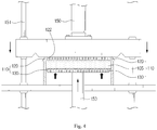
- FIG. 4 is a schematic cross-sectional view of pressing a molding space through a pressing member in a molding apparatus of a core of a vacuum insulating panel according to FIG. 1 .
- the pressing member 150 may be connected to at least one of the second surface 120b of the first molding plate 120 and the second surface 130b of the second molding plate 130 so as to move the first or second molding plates 120, 130 in the molding space M, and press the core material or core 105.
- the pressing member 150 is provided to press the first molding plate 120 and second molding plate 130, respectively.
- a guide 151 that surface-contacts the pressing member 150 and the molding plate 110 thereby guiding the moving direction of the pressing member so that the pressing member may apply an even pressure to the molding plate 110.
- a vacuum inhaler (not illustrated) to inhale the air and residue discharged through the exhaust cavity 122, 132.
- the vacuum inhaler may inhale and remove the residue on the surface of the molding plate 110.
- the core material provided to the molding space 111 in the exemplary embodiment of the present disclosure may be mixed powder where fumed silica powder, organic and inorganic fiber powder etc. are mixed therein.
- core material is provided in powder state forming a core 105.
- the core material may be provided inside the molding cast 140, on the upper side of the second molding plate 130.
- the second molding plate 130 After the core material is provided on the upper side of the second molding plate 130, with the first molding plate 120 distanced from the molding cast 140, the second molding plate 130 is moved upwards, and when the second molding plate 130 is moved upwards by a certain extent, the first molding plate 120 is moved downwards.
- the first molding plate 120 is disposed on the upper side of the molding cast 140 without moving inside the molding cast 140 but closing the opening formed on the upper side of the molding cast 140.
- the core material provided on the upper side of the second molding plate 130 contacts the first molding plate 120, the core material is pressed between the first molding plate 120 and the second molding plate 130, and the powder state raw material is compressed by a high pressure, forming a compressed product, a core 105.
- FIG. 5 is a schematic cross-sectional view of air and residue being discharged through a first molding plate and second molding plate in an apparatus for molding a core in a vacuum insulating panel according to FIG. 1 .
- the air inside the molding space M is discharged through the exhaust cast 122, 132.
- the cross-section area of the first surface 130a of the second molding plate 130 is bigger than the cross-section area of the second surface 130b so that in a pressing process, the air inside the molding space M and the residue including some core material that are not molded as a core 105 may be discharged between the molding cast 140 and the second molding plate 130, and especially, to prevent the residue from not being discharged to the space between the molding cast 140 and the second molding plate 130 due to the pressure difference during the discharge.
- first molding plate 120 and the second molding plate 130 may press 1kgf/cm 2 to 10kgf/cm 2 pressure to the core material, so as to appropriately form the pattern 121 formed on the first molding plate 120 and second molding plate 130 on the core 105.
- the first molding plate 120 and second molding plate 130 are both moved upwards while maintaining a certain distance from each other so as to prevent deformation of the core 105 by the spring back effect due to the elastic force of air gap inside the core 105 and the core material itself.
- the distance between the first molding plate 120 and second molding plate 130 is maintained to be practically the same.
- the synchronization control refers to the method of, when there is a plurality of processes being processed within a certain period of time, controlling the exact flow of control between these processes.
- the second molding plate 130 is also moved a predetermined length by the synchronization control, thereby maintaining a certain distance between the first molding plate 120 and second molding plate 130.
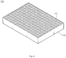
- FIG. 6 is a schematic skewed view of a pattern formed on a surface of a core in a vacuum insulation panel according to an exemplary embodiment of the present disclosure
- FIG. 7 is a schematic cross-sectional view of a vacuum insulation panel according to FIG. 6 .
- the vacuum insulation panel 200 comprises a core 210 and a packaging material 220, and is capable of easily making the interior of the packaging material 220 in a vacuum condition when vacuum packaging it through the pattern 211 formed on the exterior of the core.
- the core 210 is molded by an apparatus for molding a core of a vacuum insulation panel according to an exemplary embodiment of the present disclosure.
- a pattern portion 111 formed on a molding plate 110 on the exterior of the core there is provided a pattern 211 formed on the exterior of the core, and a pattern 211 with the same shape thereof.
- the pattern 211 of the core 210 may not only beautify the appearance of the core but also increase the elimination rate of the air inside the packaging material 220 during the packaging process of packaging the core 210 towards the outside with the packaging material 220.
- a core 210 is molded by an apparatus for molding a core of a vacuum insulation panel according to an exemplary embodiment of the present disclosure
- moisture is removed through a drying process, and a cutting process is performed to a certain standard at the user's request.
- the core 210 cut to a certain standard by the aforementioned cutting process is accommodated inside a packaging material 220, and then a vacuum packaging processing is performed where the inside of the packaging material 220 is made in a vacuum condition by removing the air inside the packaging material 220 by a vacuum pump.
- a sealing process is performed to seal the inlet of the packaging material 220.
- the air inside the packaging material is discharged up until the inside of the packaging material 220 reaches a degree of vacuum of 1mbar or less, and the pattern 211 may function as a flow path enabling air flow so as to facilitate discharging of air.
- the air is discharged starting from the area near the inlet of the packaging material 220, and the farther from the inlet of the packaging material 220, the more difficult discharging of the air becomes.
- the core 210 and the packaging material 220 would closely contact each other starting from the inlet of the packaging material 220, not creating a space for discharging the air. Accordingly, it would be difficult to discharge the air inside the packaging material 220 completely and create a vacuum condition.
- air may flow through the pattern 211 formed on the external surface of the core 210, so as to guide the air in the inside portion of the packaging material 220 to be discharged smoothely thereby discharging the maximum amount of air inside the packaging material 220.
- the packaging material 220 may be one that is suitable for creating a vacuum condition inside thereof and accommodating a core 210, and according to an exemplary embodiment of the present disclosure, it may be aluminum film.
- the packaging material 220 may be a shrink packaging film or felt that comprises a first packaging material(not illustrated) that contacts the core 210 and a second packaging material(not illustrated) made of aluminum film that covers the first packaging material so as to prevent elements such as moisture and air that deteriorates the insulating effect of the vacuum insulation panel from penetrating inside the core 210.
- the packaging material 220 when the core 210 is taken out with the core 210 accommodated inside the packaging material 220 in a vacuum condition, due to the difference of atmospheric pressure between the outside pressure and that of the inside the packaging material 220, the packaging material 220 closely contacts the core 210.
- the packaging material is desirable to provide the packaging material with the size corresponding to the size of the core 210, but the size of the packaging material 220 is generally provided to be bigger than that of the core during the cutting and sealing process, and when there is no pattern, the remaining portion that cannot contact the core when the packaging material 220 closely contacts the core 210 creates creases on the surface of the vacuum insulation panel 200.
- a portion of the packaging material 220 closely contacts between the pattern 211 of the core 210, thereby increasing the area of contact between the packaging material 220 and the core 210, preventing the remaining portion from occurring when the packaging material 220 closely contacts the core 210, consequently preventing creases from occurring on the surface of the vacuum insulation panel 200.
- the insulating effect improves, increasing the product performance.
- the table below compares a vacuum insulation panel 200 according to the exemplary embodiment of the present disclosure and a general produce not having a pattern on the surface of the core 210.
- Vacuum insulation panel according to the exemplary embodiment of the present disclosure Prior art vacuum insulation panel Height of creases on the packaging material(mm) 0.01 to 0.5 1 to 3 Gap due to the creases 0.5 or less 1 to 3
- a vacuum insulation panel may closely contact the packaging material 220 to the core 210, thereby reducing creases and minimizing the gap caused by the creases, consequently minimizing heat loss caused by the creases.
- a vacuum insulation panel according to an exemplary embodiment of the present disclosure, it is possible to beautify the appearance due to the pattern 211 on the surface of the core 210 and also increase the degree of vacuum inside the packaging material 220 since the pattern may act as a flow path for the air in a vacuum packaging process, thereby improving the insulating effect, minimizing the occurrence of creases on the surface of the vacuum insulation panel, and reducing the time needed for discharging the air inside the packaging material 220, consequently reducing the manufacturing costs.
Landscapes
- Engineering & Computer Science (AREA)
- Mechanical Engineering (AREA)
- General Engineering & Computer Science (AREA)
- Architecture (AREA)
- Civil Engineering (AREA)
- Structural Engineering (AREA)
- Casting Or Compression Moulding Of Plastics Or The Like (AREA)
- Moulds For Moulding Plastics Or The Like (AREA)
- Press-Shaping Or Shaping Using Conveyers (AREA)
- Thermal Insulation (AREA)
- Shaping Of Tube Ends By Bending Or Straightening (AREA)
Description
- The following description relates to an apparatus for molding a core of a vacuum insulation panel according to claim 1.
- Insulation panels are used to limit transference of heat in buildings, pipes, and ice boxes where there is temperature difference between the interior and exterior thereof General insulation panels or vacuum insulation panels are mostly used for the above purpose.
- A general insulation panel refers to an insulation panel having an insulation performance of 30mW/mK, whereas a vacuum insulation panel is an insulation panel having a high insulation performance of 3∼mW/mK. However, due to the high material costs and difficult manufacturing technology, insulation panels were not widely being used despite their excellent heat insulation property.
- Recently, due to significant advance of manufacturing technologies, various countries such as Germany, Great Britain, Japan, USA, Canada, Korea, and China etc. are making efforts to commercialize vacuum insulation panels, but high material costs and manufacturing process costs are becoming a burden.
- A vacuum insulation panel consists of a molded insulation body made of inorganic substances and a gas insulation film covering the molded insulation body. The biggest feature of a vacuum insulation panel is that the interior of the molded insulation body is prepared in a vacuum condition. Herein, the molded insulation body that fills the inside of the vacuum insulation panel is called a core. One way to manufacture a core is to use a glass fiber compressed material or mixed powder including silica.
- The case of using mixed powder to manufacture a core was disclosed in
KR 20120028048 KR 20120028048 -
US 4564547 ,US 2026940 ,GB 2284172 EP1098104 describe apparatus for manufacturing blocks by compacting granular material in a mold by means of a pressing tool. - However, as a molding plate for pressing mixed powder is used repeatedly, there occurs a problem where some of the mixed powder is not molded as a core and remain in the exterior surface of the molding plate, producing defective cores.
- In order to resolve this problem, felt was installed on the exterior of the molding plate so as to prevent direct contact between the molding plate and mixed powder, but when used for more than a certain number of times, the felt is damaged and thus affects the molding of the core or the apparatus must be stopped to replace the felt, thereby delaying the process time and reducing the productivity.
- Meanwhile, a manufactured core is used as a vacuum insulation panel through a packaging process where it is accommodated in a packaging material of which the interior is kept in a vacuum condition, which prevents external elements from coming inside the core, thereby increasing the durability of the vacuum insulation panel. Herein, the packaging process may be performed by accommodating the core inside the packaging material, and then discharging the air inside the packaging material outside through a vacuum pump etc.
- However, there occurs a problem where as air is discharged starting from not the inside but from outside the packaging material, the air inside the packaging material is not discharged completely or the discharge time is increased.
- The problem of the aforementioned packaging process is that the vacuum inside the vacuum insulation panel acts as a limitation to improvement, generates creases on the surface of the vacuum insulation panel, and creates leakage between the wall and the surface of the vacuum insulating panel when attaching the vacuum insulation panel to the wall, reducing the insulating effect.
- Therefore, a purpose of the present disclosure is to resolve the aforementioned problems of prior art, that is, to provide an apparatus for molding a core of a vacuum insulation panel capable of easily discharging from the molding space residue that may have negative effects on core molding.
- Another purpose of the present disclosure is to provide an apparatus for molding a core of a vacuum insulation panel capable of efficiently discharging air inside the packaging material when packaging the core by forming a pattern on an exterior surface of the core at the same time as molding the core, and a vacuum insulation panel manufactured thereby.
- In one general aspect, there is provided an apparatus for molding a core of a vacuum insulation panel, the apparatus comprising: a pair of molding plates distanced from and facing each other to form a molding space where a core is molded; a molding cast configured to close the molding space from outside; and a pressing member configured to press at least one of the pair of molding plates; wherein the at least one of the pair of molding plates comprises: a pattern portion which is provided on a first surface facing the molding space, and which transcribes a pattern on an exterior surface of the core; and an exhaust cavity penetrating the molding plate in a thickness direction from the first surface to a second surface opposite the first surface. The pair of molding plates comprises: a first molding plate that is provided on an upper side of the molding space to open and close the molding cast; and a second molding plate that is provided on a lower side of the molding space. The second molding plate, which moves in the molding space, has the first surface having a bigger cross-sectional area than a cross-sectional area of the second surface in such a manner that the distance between the molding cast and the second molding plate becomes wider in a direction away from the molding space.
- In the general aspect of the apparatus, the cross-sectional area of the exhaust cavity of a second surface may be bigger than that of the first surface.
- In the general aspect of the apparatus, the pattern portion may be provided with repeatedly arranged protrusions that protrude from the first surface and repeatedly arranged recesses that recess towards the inside of the first surface.
- In the general aspect of the apparatus, the height of the protrusion may be 0.02 mm to 0.5mm.
- In the general aspect of the apparatus, the molding plate may comprise a coating member.
- In the general aspect of the apparatus, the diameter of the exhaust cavity on the first surface may be 0.2 mm to 3mm.
- In the general aspect of the apparatus, the diameter of the exhaust cavity on the second surface may be 2 mm to 10mm.
- In the general aspect of the apparatus, the exhaust cavity may comprise an increase section where the closer to the second surface from the first surface, the bigger the diameter thereof, and a maintain section where the diameter thereof is maintained to be the same.
- In the general aspect of the apparatus, the number of exhaust cavity formed per unit of 1m2 of the molding plate may be 650 to 3300 or 1200 to 1800.
- In the general aspect of the apparatus, the molding cast may have a bigger bottom surface that faces the second molding plate than the second molding plate.
- According to the present disclosure, there is provided an apparatus for molding a core of a vacuum insulation panel that may easily discharge residue that are attached to the exterior surface of the molding plate and have negative effects when molding the core, and a vacuum insulation panel manufactured thereby.
- In addition, the diameter of an exhaust cavity of the molding plate may be formed in such a manner that the farther away from the core, the bigger the diameter of the exhaust cavity of the molding plate, thereby preventing the core material being stuck in the exhaust cavity and the exhaust cavity being blocked.
- Furthermore, as the powder provided in the molding space through the coating member contact the molding plate, it is possible to prevent the powder from being attached to the molding plate.
- In addition, it is possible to easily form shapes, letter etc. that a user wants on the exterior of the core.
- Furthermore, it is possible to prevent movement of the molding plate being limited by the core material stuck between the molding plate and molding cast.
- In addition, it is possible to facilitate discharging of air during the packaging process through a pattern formed on the core, thereby enhancing the adherence of the packaging material and the core.
- Furthermore, it is possible to improve the appearance of exterior of the vacuum insulation panel through the pattern formed on the core.
- Other features and aspects may be apparent from the following detailed description, the drawings, and the claims.
-
-
FIG. 1 is a schematic skewed view of an apparatus for molding a core of a vacuum insulating panel according to an exemplary embodiment of the present disclosure. -
FIG. 2 is a schematic cross-sectional view of an apparatus for molding a core of a vacuum insulating panel according toFIG. 1 . -
FIG. 3 is a schematic bottom view illustrating a first molding plate in an apparatus for molding a core of a vacuum insulating panel according toFIG. 1 . -
FIG. 4 is a schematic cross-sectional view of pressing a molding space through a pressing member in an apparatus for molding a core of a vacuum insulating panel according toFIG. 1 . -
FIG. 5 is a schematic cross-sectional view of air and residue being discharged through a first molding plate and second molding plate in an apparatus for molding a core in a vacuum insulating panel according toFIG. 1 . -
FIG. 6 is a schematic skewed view of a pattern formed on a surface of a core in a vacuum insulation panel according to an exemplary embodiment of the present disclosure. -
FIG. 7 is a schematic cross-sectional view of a vacuum insulation panel according toFIG. 6 . - Throughout the drawings and the detailed description, unless otherwise described, the same drawing reference numerals will be understood to refer to the same elements, features, and structures. The relative size and depiction of these elements may be exaggerated for clarity, illustrating, and convenience.
- The following detailed description is provided to assist the reader in gaining a comprehensive understanding of the methods, apparatuses, and/or systems described herein. Accordingly, various changes, modifications, and equivalents of the systems, apparatuses and/or methods described herein will be suggested to those of ordinary skill in the art. Also, descriptions of well-known functions and constructions may be omitted for increased clarity and conciseness.
- Hereinbelow is detailed description of an apparatus for molding a core of a vacuum insulation panel according to an exemplary embodiment of the present disclosure with reference to the drawings attached hereto.
-
FIG. 1 is a schematic skewed view of an apparatus for molding a core of a vacuum insulating panel according to an exemplary embodiment of the present disclosure, andFIG. 2 is a schematic cross-sectional view of an apparatus for molding a core of a vacuum insulating panel according toFIG. 1 . - With reference to
FIG. 1 orFIG. 2 , the apparatus for molding a core of a vacuum insulation panel according to an exemplary embodiment of thepresent disclosure 100 may form a specific pattern on a surface of the core at the same time of molding the core, and may easily discharge from the molding space the air inside the core material that forms the core and the floating particles that may be generated in the molding process. The apparatus for molding a core of avacuum insulation panel 100 comprises amolding plate 110,molding cast 140, and apressing member 150. - The
molding plate 110 is provided as a pair of plate members that face each other and are distanced from each other, forming a molding space M that is a space between the pair ofmolding plates 110. Themolding plate 110 presses and compresses the core material provided inside the molding space M, and in the exemplary embodiment of the present disclosure, the pair ofmolding plates 110 comprises afirst molding plate 120 disposed on the upper side and asecond molding plate 130 disposed on the lower side, the twomolding plates -
FIG. 3 is a schematic bottom view illustrating a first molding plate in an apparatus for molding a core of a vacuum insulation panel according toFIG. 1 . - With reference to
FIG. 3 , thefirst molding plate 120 presses the molding space M from the upper side. On afirst surface 120a that is adjacent to the molding space M, a pattern portion 121 is formed so that the core material is pressed and molded at the same time a pattern is formed, and anexhaust cavity 122 is formed that penetrates thefirst surface 120a and asecond surface 120b(seeFIG. 5 ) - The pattern portion 121 is provided in a particular pattern on the
first surface 120a of themolding plate 120 such that a same shape is transcript on an exterior surface of thecore 105 when molding thecore 105. - Herein, the pattern portion 121 is provided in a predetermined shape according to the manufacturer's intentions. Herein, a particular shape may be repeatedly formed such that the overall shape has the predetermined shape.
- Especially, the pattern portion 121 may be utilized as a flow path of air when packaging the
core 150 molded according to the exemplary embodiment of the present disclosure with the packaging material and thus may improve the degree of vacuum. - Herein, in order to be utilized as a flow path for air, the pattern portion 121 may comprise as a
protrusion 121a that is protruded towards the outside of thefirst surface 120a and arecess 121b that is recessed towards the inside of thefirst surface 120a. The pattern portion 121 may facilitate the air flow, and may reduce the power consumption of a vacuum pump and vacuum pumping time necessary to have the interior of the packaging material in a vacuum condition. For example, the height of theprotrusion 121a or the depth of therecess 121b may be 0.02mm to 0.5mm. - The
exhaust cavity 122 is a path that may discharge the air inside the molding space M during a molding process. Theexhaust cavity 122 penetrates thefirst molding plate 120. On thefirst molding plate 120, the exhaust cavity 122b(seeFIG. 5 ) of thesecond surface 120b side is bigger than theexhaust cavity 122a(seeFIG. 5 ) of thefirst surface 120a side. - This is to prevent some of the core material from blocking the
exhaust cavity 122 when being discharged together with the air inside the molding space M, that is to prevent theexhaust cavity 122 being blocked by the core material and interrupting the air or residue being discharged. - The abovementioned function is one of the basic principles of fluid mechanics that can be explained by the Bernoulli's Theorem that the physicist Bernoulli announced in 1738. Herein, the Bernoulli's Theorem refers to a mathematical formula as shown below representing a relationship between the velocity, pressure and height when an ideal fluid that is incompressible inviscid flows.

- Herein, P represents the pressure of the fluid at a particular point, p represents the density of the fluid, v represents the velocity at a particular point, g represents the acceleration of gravity, and h represents the height at a particular point. When the above formula is applied to the
exhaust cavity 122 according to the exemplary embodiment of the present disclosure, the difference of height between thefirst surface 120a and thesecond surface 120b, that is the thickness of thefirst molding plate 120 is negligibly small, and thus gh which means the kinetic energy in the above mathematical formula could be disregarded, showing that the fluid velocity v and the pressure P are inversely proportional to each other. - In addition, a continuity equation that is another expression of the mass conservation law is as shown below.

- Herein, Q represents the discharge amount, A represents the cross sectional area that the fluid passes, and v represents the velocity of the fluid. That is, it can be seen that the velocity of the fluid and the cross sectional area that the fluid passes when flowing through a particular area are inversely proportional to each other.
- Assuming that the air flow from the molding space M along the
exhaust cavity 122 is a laminar flow, when applying the aforementioned Bernoulli's Theorem and the continuity equation to theexhaust cavity 122 and molding space M of the present disclosure, regarding the cross-sectional size A, the cross-sectional size at the molding space M (A0) is the greatest, followed by the cross-sectional size of theexhaust cavity 122a of thefirst surface 120a side (A1), followed by the cross-sectional size of the exhaust cavity 122b of thesecond surface 120b side (A2). - When this is applied to the continuity equation, regarding the velocity of fluid, the velocity of fluid passing the
exhaust cavity 122a of thefirst surface 120a side is the fastest, followed by the velocity of fluid passing the exhaust cavity 122b of thesecond surface 120b side, followed by the velocity of fluid inside the molding space M. - Thus,


relationship is established. - Herein, when residue is attached to the
exhaust cavity 122, the kinetic energy of the fluid being discharged may act as energy source for pushing the residue out from theexhaust cavity 122, and since the kinetic energy is proportionate to the square of velocity, residue may be pushed out most actively from theexhaust cavity 122a of thefirst surface 120a side having the fastest fluid discharge velocity. - In addition, the viscosity force of the fluid being discharged may act as the force for pushing out the residue attached to the
exhaust cavity 122 from theexhaust cavity 122, and since the viscosity force is proportionate to velocity, residue may be pushed out most actively from theexhaust cavity 122a of thefirst surface 120a side having the fastest fluid discharge velocity. - In other words, since the kinetic energy and viscosity force of fluid that may act as a cause for pushing out residue from the
exhaust cavity 122 acts the greatest at theexhaust cavity 122a of thefirst surface 120a, residue may be discharged most actively from theexhaust cavity 122a of thefirst surface 120a side. - In addition, when the Bernoulli's Theorem is applied to the aforementioned relationship,

relationship is established. - Consequently, since the pressure P0 inside the molding space M is significantly bigger than the pressure P1 at the
exhaust cavity 122a and the pressure P2 at the exhaust cavity 122b of thesecond surface 120b, regardless of size of the pressure P1 at theexhaust cavity 122a of thefirst surface 120a side and the size of the pressure P2 at the exhaust cavity 122b of thesecond surface 120b, the fluid inside the molding space M may be discharged smoothly along theexhaust cavity 122 from the molding space M. - Herein, when the Bernoulli's Theorem is applied, v1 > v2, P1<P2 relationship is established, and as a result, the pressure P1 at the
exhaust cavity 122a of thefirst surface 120a side is greater than the pressure P2 of the fluid at the exhaust cavity 122b of thesecond surface 120b side, and even if some of the raw material is discharged through theexhaust cavity 122, some of the raw material would not accumulate in theexhaust cavity 122a of thefirst surface 120a side, but would float to the exhaust cavity 122b of thesecond surface 120b and be discharged to the exterior. - Therefore, it is possible to smoothly perform the process of molding the core by adjusting the size of the
exhaust cavity 122a of thefirst surface 120a and the exhaust cavity 122b of thesecond surface 120b as long as theexhaust cavity 122a of thefirst surface 120a side is smaller than the size of the exhaust cavity 122b of thesecond surface 120b. - For example, the diameter of the
exhaust cavity 122a of thefirst surface 120a may be between the range of 0.2mm to 3.0mm, and the diameter of the exhaust cavity 122b of thesecond surface 120b may be between the range of 2.0mm to 10.0mm as long as it is bigger than theexhaust cavity 122a of thefirst surface 120a. - For example, according to an exemplary embodiment of the present disclosure, the diameter of the
exhaust cavity 122a of thefirst surface 120a may be 1.5mm and the diameter of the exhaust cavity 122b of thesecond surface 120b may be 5.0mm. - Herein, the diameter of the
exhaust cavity 122a of thefirst surface 120a side and the diameter cavity 122b of thesecond surface 120b side may be determined in comprehensive consideration of the components of thecore 105, and the pressure on the molding space M during thecore 105 molding process. - Meanwhile, according to the present exemplary embodiment of the present disclosure, the
exhaust cavity 122 may comprise an increase section where the closer to thesecond surface 120b side from thefirst surface 120a, the bigger the area of cross-section, and a maintain section where the area of cross-section is maintained to be the same. - Otherwise, the
exhaust cavity 122 may only comprise an increase section where the closer to thesecond surface 120b side from thefirst surface 120a the bigger the area of cross-section. Herein, theexhaust cavity 122 may be of any shape as long as the size of theexhaust cavity 122a of thefirst surface 120a side is smaller than the size of the exhaust cavity 122b of thesecond surface 120b side. - Meanwhile, the number of the
exhaust cavity 122 may be adjusted such that the air of the molding space M may be discharged appropriately. 650 to 3300, and more desirably 1200 to 1800exhaust cavity 122 may be provided per unit area 1m2 of themolding plate 110 so as to prevent loss of pressure on thefirst molding plate 120 from the upper side while appropriately discharging the air of the molding space M. - Herein, each
exhaust cavity 122 may be distanced by a distance of 15mm to 40mm from one another and form a grid. - Meanwhile, the
exhaust cavity 122 may discharge air of the molding space M during upward movement of thefirst molding plate 120 thereby reducing the resistance caused by the air and facilitating movement of thefirst molding plate 120. - Meanwhile, the exterior surface of the
first molding plate 120 may be coated with a coating member(not illustrated). The coating member(not illustrated) may prevent residue including core material etc. from remaining on thefirst molding plate 120. - Furthermore, in the process where the
core 105 contacting thefirst molding plate 120 is detached from thefirst molding plate 120 by the coating member(not illustrated), the coating member(not illustrated) may prevent the core material from being attached to the surface of thefirst molding plate 120. - Herein, the coating member(not illustrated) may be made of a fluoroplastic material.
- More specifically, the coating member(not illustrated) of the
first molding plate 120 is made of a fluoroplastic material having weak adhesion, and thus prevents the core from being damaged when thefirst molding plate 120 is distanced from thecore 105. Likewise, the coating member(not illustrated) of thefirst molding plate 120 is made of a fluoroplastic material having low friction coefficient and adhesion, and thus may prevent the core from being damaged when discharging thecore 105. - That is, using the coating member(not illustrated), it is possible to prevent residue from being attached on the
molding plate 110 and to lower the friction coefficient between the core 105 and themolding plate 110 thereby preventing the core from being damaged when discharging the core. - The
second molding plate 130 is a molding plate that is provided on the lower side of the molding space M such that it faces themolding plate 120. Thesecond molding plate 130 is practically the same as the aforementionedfirst molding plate 120 except that it is disposed on the lower side of themolding apparatus 100, and thus detailed explanation thereof is omitted. - However, in the
second molding plate 130, the cross-section area of thefirst surface 130a near the molding space M is bigger than the cross-section area of thesecond surface 130b. Accordingly, the farther away from the molding space M, the wider the distance between thesecond molding plate 130 and themolding cast 140. Such a shape performs practically the same function as theaforementioned exhaust cavity 122, thereby easily discharging the air inside the molding space M and residue including some of the core material and preventing them from being adhered between thesecond molding plate 130 andmolding cast 140. - In addition, by reducing the area of contact between the
second molding plate 130 and molding cast 140, it is possible to reduce the mechanical interference by the contact of thesecond molding plate 130 and molding cast 140 and reduce the air exhaust resistance, during an up-and-down movement of thesecond molding plate 130. - The molding cast 140 is a cast for closing the molding space M from outside and for determining the shape of the
core 105 when molding the core. - The molding cast 140 in the exemplary embodiment of the present disclosure wraps around the side of the molding space M, and the upper surface and the lower surface are open to the exterior.
- The pressing
member 150 presses themolding plate 110 to press the core material from the inside of the molding space M. The pressing member150 according to an exemplary embodiment of the present disclosure is a well known technology and thus detailed explanation is omitted. - However, according to the exemplary embodiment of the present disclosure, the pressing
member 150 is provided to apply preferably 1kgf/cm2 to 10kgf/cm2 of pressure to the molding space M. By pressing the core 105 with a pressure of such range, the pattern formed on the first surface of themolding plate 110 may be sufficiently transcript on the surface of thecore 105, while minimizing the power consumption necessary for driving thepressing member 150 and easily controlling the density of thecore 105. - Herein, the pressure applied by the pressing
member 150 may be 1kgf/cm2 to 10kgf/cm2 in consideration of not only the density of the core 105 but also the number and size of theexhaust cavity molding plate 110. -
FIG. 4 is a schematic cross-sectional view of pressing a molding space through a pressing member in a molding apparatus of a core of a vacuum insulating panel according toFIG. 1 . - Meanwhile, the pressing
member 150 may be connected to at least one of thesecond surface 120b of thefirst molding plate 120 and thesecond surface 130b of thesecond molding plate 130 so as to move the first orsecond molding plates core 105. With reference toFIG. 4 , according to the exemplary embodiment of the present disclosure, the pressingmember 150 is provided to press thefirst molding plate 120 andsecond molding plate 130, respectively. - In addition, there may be further provided a
guide 151 that surface-contacts thepressing member 150 and themolding plate 110 thereby guiding the moving direction of the pressing member so that the pressing member may apply an even pressure to themolding plate 110. - Furthermore, on the surface of the
pressing member 150 facing themolding plate 110, there may be provided a vacuum inhaler(not illustrated) to inhale the air and residue discharged through theexhaust cavity - Herein, the vacuum inhaler(not illustrated) may inhale and remove the residue on the surface of the
molding plate 110. - Meanwhile, the core material provided to the molding space 111 in the exemplary embodiment of the present disclosure may be mixed powder where fumed silica powder, organic and inorganic fiber powder etc. are mixed therein.
- The following is an explanation on operating an exemplary embodiment of an apparatus for molding a core of a vacuum insulation panel explained above.
- First of all, on the upper side of the
second molding plate 130, core material is provided in powder state forming acore 105. The core material may be provided inside the molding cast 140, on the upper side of thesecond molding plate 130. - After the core material is provided on the upper side of the
second molding plate 130, with thefirst molding plate 120 distanced from the molding cast 140, thesecond molding plate 130 is moved upwards, and when thesecond molding plate 130 is moved upwards by a certain extent, thefirst molding plate 120 is moved downwards. Herein, thefirst molding plate 120 is disposed on the upper side of the molding cast 140 without moving inside the molding cast 140 but closing the opening formed on the upper side of themolding cast 140. - This is because the
second molding plate 130 moves with the upper side of the molding cast 140 open, and thus it is possible to accelerate the movement speed of thesecond molding plate 130, thereby reducing the time spent in a molding process. - When the core material provided on the upper side of the
second molding plate 130 contacts thefirst molding plate 120, the core material is pressed between thefirst molding plate 120 and thesecond molding plate 130, and the powder state raw material is compressed by a high pressure, forming a compressed product, acore 105. -
FIG. 5 is a schematic cross-sectional view of air and residue being discharged through a first molding plate and second molding plate in an apparatus for molding a core in a vacuum insulating panel according toFIG. 1 . - Meanwhile, with reference to
FIG. 5 , in the moving process and pressing process of thefirst molding plate 120 andsecond molding plate 130, the air inside the molding space M is discharged through the exhaust cast 122, 132. - Herein, the cross-section area of the
first surface 130a of thesecond molding plate 130 is bigger than the cross-section area of thesecond surface 130b so that in a pressing process, the air inside the molding space M and the residue including some core material that are not molded as acore 105 may be discharged between the molding cast 140 and thesecond molding plate 130, and especially, to prevent the residue from not being discharged to the space between the molding cast 140 and thesecond molding plate 130 due to the pressure difference during the discharge. - Meanwhile, the
first molding plate 120 and thesecond molding plate 130 may press 1kgf/cm2 to 10kgf/cm2 pressure to the core material, so as to appropriately form the pattern 121 formed on thefirst molding plate 120 andsecond molding plate 130 on thecore 105. - Meanwhile, to take out the
core 105 that has been formed by compressing with the pressure received from themolding plate 110, it is possible to perform a process of detaching the core from inside themolding cast 140. - In the process of performing the aforementioned, the
first molding plate 120 andsecond molding plate 130 are both moved upwards while maintaining a certain distance from each other so as to prevent deformation of thecore 105 by the spring back effect due to the elastic force of air gap inside thecore 105 and the core material itself. - Herein, by performing a synchronization control on the
first molding plate 120 andsecond molding plate 130, the distance between thefirst molding plate 120 andsecond molding plate 130 is maintained to be practically the same. - Herein, the synchronization control refers to the method of, when there is a plurality of processes being processed within a certain period of time, controlling the exact flow of control between these processes.
- That is, when the
first molding plate 120 is moved a predetermined length, thesecond molding plate 130 is also moved a predetermined length by the synchronization control, thereby maintaining a certain distance between thefirst molding plate 120 andsecond molding plate 130. - Next is explanation on a vacuum insulation panel manufactured by an apparatus for molding a core of a vacuum insulation panel explained above.
-
FIG. 6 is a schematic skewed view of a pattern formed on a surface of a core in a vacuum insulation panel according to an exemplary embodiment of the present disclosure, andFIG. 7 is a schematic cross-sectional view of a vacuum insulation panel according toFIG. 6 . - With reference to
FIGs. 6 and7 , thevacuum insulation panel 200 according to an exemplary embodiment of the present disclosure comprises acore 210 and apackaging material 220, and is capable of easily making the interior of thepackaging material 220 in a vacuum condition when vacuum packaging it through thepattern 211 formed on the exterior of the core. - The
core 210 is molded by an apparatus for molding a core of a vacuum insulation panel according to an exemplary embodiment of the present disclosure. On thecore 210, there is provided a pattern portion 111 formed on amolding plate 110 on the exterior of the core, and apattern 211 with the same shape thereof. - Herein, the
pattern 211 of thecore 210 may not only beautify the appearance of the core but also increase the elimination rate of the air inside thepackaging material 220 during the packaging process of packaging thecore 210 towards the outside with thepackaging material 220. - Prior to explaining such a function of the
pattern 211, the following is an explanation on a process for manufacturing a vacuum insulation panel after a molding process. - When a
core 210 is molded by an apparatus for molding a core of a vacuum insulation panel according to an exemplary embodiment of the present disclosure, moisture is removed through a drying process, and a cutting process is performed to a certain standard at the user's request. - In addition, the
core 210 cut to a certain standard by the aforementioned cutting process is accommodated inside apackaging material 220, and then a vacuum packaging processing is performed where the inside of thepackaging material 220 is made in a vacuum condition by removing the air inside thepackaging material 220 by a vacuum pump. - After the aforementioned vacuum packaging process, a sealing process is performed to seal the inlet of the
packaging material 220. - Herein, it is desirable that the air inside the packaging material is discharged up until the inside of the
packaging material 220 reaches a degree of vacuum of 1mbar or less, and thepattern 211 may function as a flow path enabling air flow so as to facilitate discharging of air. - In other words, in the case of discharging the air inside the
packaging material 220 through the aforementioned vacuum packaging process, the air is discharged starting from the area near the inlet of thepackaging material 220, and the farther from the inlet of thepackaging material 220, the more difficult discharging of the air becomes. - If there were no
pattern 211 formed on the core, once the air is discharged to some degree, thecore 210 and thepackaging material 220 would closely contact each other starting from the inlet of thepackaging material 220, not creating a space for discharging the air. Accordingly, it would be difficult to discharge the air inside thepackaging material 220 completely and create a vacuum condition. - Therefore, in the case of packaging a
core 200 not having apattern 211, creases would occur on the surface of the vacuum insulation panel due to the air not discharged. - However, according to the exemplary embodiment of the present disclosure, air may flow through the
pattern 211 formed on the external surface of thecore 210, so as to guide the air in the inside portion of thepackaging material 220 to be discharged smoothely thereby discharging the maximum amount of air inside thepackaging material 220. - The
packaging material 220 may be one that is suitable for creating a vacuum condition inside thereof and accommodating a core 210, and according to an exemplary embodiment of the present disclosure, it may be aluminum film. - Otherwise, the
packaging material 220 may be a shrink packaging film or felt that comprises a first packaging material(not illustrated) that contacts thecore 210 and a second packaging material(not illustrated) made of aluminum film that covers the first packaging material so as to prevent elements such as moisture and air that deteriorates the insulating effect of the vacuum insulation panel from penetrating inside thecore 210. - Meanwhile, regarding the combination relationship between the core 210 and the
packaging material 220, when thecore 210 is taken out with thecore 210 accommodated inside thepackaging material 220 in a vacuum condition, due to the difference of atmospheric pressure between the outside pressure and that of the inside thepackaging material 220, thepackaging material 220 closely contacts thecore 210. - Herein, it is desirable to provide the packaging material with the size corresponding to the size of the
core 210, but the size of thepackaging material 220 is generally provided to be bigger than that of the core during the cutting and sealing process, and when there is no pattern, the remaining portion that cannot contact the core when thepackaging material 220 closely contacts thecore 210 creates creases on the surface of thevacuum insulation panel 200. - However, when a
pattern 211 is formed on thecore 210, a portion of thepackaging material 220 closely contacts between thepattern 211 of thecore 210, thereby increasing the area of contact between thepackaging material 220 and thecore 210, preventing the remaining portion from occurring when thepackaging material 220 closely contacts thecore 210, consequently preventing creases from occurring on the surface of thevacuum insulation panel 200. - As aforementioned, when the degree of adherence of the
packaging material 220 to thecore 210 improves, the insulating effect improves, increasing the product performance. - The table below compares a
vacuum insulation panel 200 according to the exemplary embodiment of the present disclosure and a general produce not having a pattern on the surface of thecore 210.Vacuum insulation panel according to the exemplary embodiment of the present disclosure Prior art vacuum insulation panel Height of creases on the packaging material(mm) 0.01 to 0.5 1 to 3 Gap due to the creases 0.5 or less 1 to 3 - According to the above table, a vacuum insulation panel according to an exemplary embodiment of the present disclosure may closely contact the
packaging material 220 to thecore 210, thereby reducing creases and minimizing the gap caused by the creases, consequently minimizing heat loss caused by the creases. - In a vacuum insulation panel according to an exemplary embodiment of the present disclosure, it is possible to beautify the appearance due to the
pattern 211 on the surface of thecore 210 and also increase the degree of vacuum inside thepackaging material 220 since the pattern may act as a flow path for the air in a vacuum packaging process, thereby improving the insulating effect, minimizing the occurrence of creases on the surface of the vacuum insulation panel, and reducing the time needed for discharging the air inside thepackaging material 220, consequently reducing the manufacturing costs. - A number of examples have been described above. Nevertheless, it will be understood that various modifications may be made. For example, suitable results may be achieved if the described techniques are performed in a different order and/or if components in a described system, architecture, device, or circuit are combined in a different matter and/or replaced or supplemented by other components or their equivalents. Accordingly, other implementations are within the scope of the following claims.
-
- 110:
- MOLDING PLATE
- 120:
- FIRST MOLDING PLATE
- 130:
- SECOND MOLDING PLATE
- 140:
- MOLDING CAST
- 150:
- PRESSING MEMBER
- 200:
- VACUUM INSULATION PANEL
- 210:
- CORE
- 220:
- PACKAGING MATERIAL
Claims (9)
- An apparatus (100) for molding a core of a vacuum insulation panel, the apparatus (100) comprising:a pair of molding plates (120, 130) distanced from and facing each other to form a molding space (M) where a core (210) is molded;a molding cast (140) configured to close the molding space (M) from outside; anda pressing member (150) configured to press at least one of the pair of molding plates (120, 130);wherein the at least one of the pair of molding plates (120, 130) comprises:a pattern portion (121) which is provided on a first surface (120a, 130a) facing the molding space and which transcribes a pattern on an exterior surface of the core (210); andan exhaust cavity (122) penetrating the molding plate (120, 130) in a thickness direction from the first surface (120a, 130a) to a second surface (120b, 130b) opposite the first surface (120a, 130a),wherein the pair of molding plates (120, 130) comprises a first molding plate (120) that is provided on an upper side of the molding cast (140) to open and close the molding cast (140) and a second molding plate (130) that is provided on a lower side of the molding space (M), and wherein the second molding plate (130) which moves in the molding space (M) has the first surface (130a) near the molding space (M) having a bigger cross-sectional area than a cross-sectional area of the second surface (130b) such that the farther away from the molding space (M), the wider the distance between the second molding plate (130) and molding cast (140) becomes.
- The apparatus (100) according to claim 1, wherein the cross-sectional area of the exhaust cavity (122, 132) of a second surface (120b, 130b) is bigger than that of the first surface (120a, 130a).
- The apparatus (100) according to claim 2, wherein the diameter of the exhaust cavity (122, 132) on the first surface (120a, 130a) is 0.2 mm to 3mm.
- The apparatus (100) according to claim 2, wherein the diameter of the exhaust cavity (122, 132) on the second surface (120b, 130b) is 2 mm to 10mm.
- The apparatus (100) according to claim 2, wherein the exhaust cavity (122, 132) comprises an increase section where the closer to the second surface (120b, 130b) from the first surface (120a, 130a), the bigger the diameter thereof, and a maintain section where the diameter thereof is maintained to be the same.
- The apparatus (100) according to any one of the preceding claims,
wherein the pattern portion (121) is provided with repeatedly arranged protrusions (121a) that protrude from the first surface (120a, 130a) and repeatedly arranged recesses (121b) that recess towards the inside of the first surface (120a, 130a). - The apparatus (100) according to claim 6,
wherein the height of the protrusion (121a) is 0.02 mm to 0.5mm. - The apparatus (100) according to any one of the preceding claims,
wherein the molding plate (120, 130) comprises a coating member. - The apparatus (100) according to claim 1,
wherein the molding cast (140) has a bigger bottom surface that faces the second molding plate (130) than the second molding plate (130).
Applications Claiming Priority (2)
| Application Number | Priority Date | Filing Date | Title |
|---|---|---|---|
| KR20120125370 | 2012-11-07 | ||
| KR20120129401 | 2012-11-15 |
Publications (3)
| Publication Number | Publication Date |
|---|---|
| EP2730398A2 EP2730398A2 (en) | 2014-05-14 |
| EP2730398A3 EP2730398A3 (en) | 2014-07-09 |
| EP2730398B1 true EP2730398B1 (en) | 2017-05-31 |
Family
ID=49578114
Family Applications (3)
| Application Number | Title | Priority Date | Filing Date |
|---|---|---|---|
| EP13192020.9A Active EP2730400B1 (en) | 2012-11-07 | 2013-11-07 | Method for molding a core of a vacuum insulation panel |
| EP13192009.2A Active EP2730399B1 (en) | 2012-11-07 | 2013-11-07 | System for manufacturing core of vacuum insulation panel |
| EP13192008.4A Active EP2730398B1 (en) | 2012-11-07 | 2013-11-07 | Apparatus for molding core of vacuum insulation panel and vacuum insulation panel manufactured thereby |
Family Applications Before (2)
| Application Number | Title | Priority Date | Filing Date |
|---|---|---|---|
| EP13192020.9A Active EP2730400B1 (en) | 2012-11-07 | 2013-11-07 | Method for molding a core of a vacuum insulation panel |
| EP13192009.2A Active EP2730399B1 (en) | 2012-11-07 | 2013-11-07 | System for manufacturing core of vacuum insulation panel |
Country Status (5)
| Country | Link |
|---|---|
| US (3) | US20140127470A1 (en) |
| EP (3) | EP2730400B1 (en) |
| JP (3) | JP5745595B2 (en) |
| KR (3) | KR101552018B1 (en) |
| CN (3) | CN103802350B (en) |
Families Citing this family (12)
| Publication number | Priority date | Publication date | Assignee | Title |
|---|---|---|---|---|
| JP2016033419A (en) | 2014-07-29 | 2016-03-10 | 旭硝子株式会社 | Manufacturing method of heat insulation plate and vacuum heat insulation material |
| JP6476794B2 (en) * | 2014-11-27 | 2019-03-06 | Agc株式会社 | Manufacturing method of heat insulating plate and manufacturing apparatus thereof, and vacuum heat insulating material and manufacturing method thereof |
| CN105149392B (en) * | 2015-09-22 | 2018-03-09 | 苏州维艾普新材料股份有限公司 | A kind of indent method of special-shaped core material of vacuum heat insulation plate |
| CN106003374B (en) * | 2016-07-19 | 2018-11-27 | 东莞市唯美陶瓷工业园有限公司 | Production equipment for ultrathin fabric whole-body porcelain tile |
| CN106978859B (en) * | 2017-03-31 | 2019-11-22 | 北京微纳宏创科技有限公司 | A kind of vacuum insulation panel and preparation method thereof allowing any cutting |
| CN110126242A (en) * | 2018-02-02 | 2019-08-16 | 广州金发碳纤维新材料发展有限公司 | A kind of the suction type molding device and its mould pressing method of cellular thermoplastic plate |
| ES2708400B2 (en) * | 2019-02-06 | 2019-10-29 | Kuhamisha Tech S L | Flexible continuous vacuum insulation panel |
| CN111634048A (en) * | 2020-05-20 | 2020-09-08 | 安徽牧洋饲料科技有限公司 | Oil residue re-pressing separation device for oil production |
| CN111572906B (en) * | 2020-05-22 | 2021-09-14 | 振德医疗用品股份有限公司 | Online bag pressing and forming equipment |
| CN113681966B (en) * | 2021-07-19 | 2023-04-07 | 安徽中马磁能科技股份有限公司 | Production equipment for magnetic material |
| CN114347339B (en) * | 2021-12-03 | 2024-09-06 | 上饶贝龙软件中心(个人独资) | A thermosetting plastic shell molding equipment for small car equipment manufacturing |
| CN114536840B (en) * | 2022-02-28 | 2024-05-10 | 卓马(深圳)装饰创新科技有限公司 | Building loam compression processing device |
Family Cites Families (77)
| Publication number | Priority date | Publication date | Assignee | Title |
|---|---|---|---|---|
| US390747A (en) * | 1888-10-09 | Bob-sleigh | ||
| US2026940A (en) * | 1934-12-13 | 1936-01-07 | Harbison Walker Refractories | Shaping refractory articles |
| DE1584664A1 (en) | 1966-03-12 | 1970-03-26 | Dolomitwerke Gmbh | Method and device for controlling a press metering |
| DE2334499A1 (en) | 1972-07-20 | 1974-01-31 | Von Roll Ag | METHOD AND DEVICE FOR THE PRODUCTION OF BLOCKS |
| US4005956A (en) * | 1973-04-11 | 1977-02-01 | Inoue-Japax Research Incorporated | Powder activation and integrated powder metallurgy system |
| US3890413A (en) * | 1974-08-15 | 1975-06-17 | Hydramet American Inc | Apparatus and method for compacting particulate materials |
| US4047864A (en) * | 1975-10-06 | 1977-09-13 | Wolverine Aluminum Corporation | Apparatus for producing spherical articles |
| JPS52111916A (en) * | 1976-03-17 | 1977-09-20 | Kouji Miyazaki | Apparatus for continuous production of roof tile |
| CA1075140A (en) * | 1976-09-23 | 1980-04-08 | Donald W. Nyberg | Method and apparatus for consolidating particle board |
| US4335065A (en) * | 1979-12-17 | 1982-06-15 | Shigeo Ando | Method and apparatus for producing mouldings of cement mortar |
| US4327049A (en) * | 1980-02-14 | 1982-04-27 | Miller Frederick O | Method of forming automotive headliners from composite foamed resin blanks |
| JPS5931369Y2 (en) * | 1981-03-02 | 1984-09-05 | 株式会社 石川時鉄工所 | roof tile forming machine |
| JPS5938082B2 (en) * | 1981-03-24 | 1984-09-13 | 株式会社 石川時鉄工所 | Flower pot press molding machine |
| GB2106823B (en) * | 1981-09-03 | 1985-08-14 | Lucas Ind Plc | Producing a friction element for a disc brake |
| JPS59158242A (en) * | 1983-02-28 | 1984-09-07 | Nippon Sekisoo Kogyo Kk | Method for molding molded article of organic substance |
| SE466299B (en) * | 1983-08-04 | 1992-01-27 | Micropore International Ltd | HEAT-INSULATING BODY AND MAKING IT MANUFACTURED, INCLUDING A REINFORCING HONEY STRUCTURE AND A HEATING INSULATION MATERIAL |
| GB8715471D0 (en) * | 1987-07-01 | 1987-08-05 | Micropore International Ltd | Moulding thermal insulation |
| ES2021657B3 (en) * | 1987-09-02 | 1991-11-16 | Theodor Grabener Pressensysteme Gmbh & Co Kg | PRESS TO PRODUCE PRESSED PIECES OF SPRAY MATERIAL. |
| JPH02251400A (en) | 1989-03-24 | 1990-10-09 | Ishikawajima Harima Heavy Ind Co Ltd | Powder molding press equipment |
| JP2889990B2 (en) * | 1990-08-06 | 1999-05-10 | セイコーインスツルメンツ株式会社 | Powder molding method |
| JPH07112638B2 (en) * | 1991-05-02 | 1995-12-06 | 株式会社ヨシツカ精機 | Pressure control method for powder molding press |
| US5489408A (en) * | 1993-03-08 | 1996-02-06 | Agency Of Industrial Science & Technology | Method for producing ceramics reinforced with three-dimensional fibers |
| JP2980484B2 (en) * | 1993-06-14 | 1999-11-22 | コータキ精機株式会社 | Die set type powder molding press |
| US5648033A (en) * | 1993-09-10 | 1997-07-15 | Fuisz Technologies Ltd. | Method and apparatus for retaining a formed compression dosage unit within a die cavity |
| CH686785A5 (en) * | 1993-10-06 | 1996-06-28 | Matec Holding Ag | Odour Armer, sound and waermedaemmender Formkoerper and method for its manufacture. |
| EP0680405B1 (en) * | 1993-11-24 | 1999-08-04 | Stackpole Limited | Phased split die |
| US6099772A (en) * | 1993-11-24 | 2000-08-08 | Stackpole Limited | Undercut split die |
| GB2284172B (en) * | 1993-11-25 | 1997-07-30 | Ceramaspeed Ltd | Method of forming compacted layer |
| US5580586A (en) * | 1994-03-17 | 1996-12-03 | Tamagawa Machinery Co., Ltd. | Die control speed rate conversion device for powder mold press |
| DE59506072D1 (en) * | 1994-04-27 | 1999-07-08 | Dorst Masch & Anlagen | Process for the production of compacts from powdery material and corresponding press |
| DE4432896C2 (en) * | 1994-09-15 | 2002-08-29 | Wacker Chemie Gmbh | Evacuated, thermally insulating molded body |
| US6440357B1 (en) * | 1996-05-09 | 2002-08-27 | Stackpole Limited | Compacted-powder opposed twin-helical gears and method |
| IT1287505B1 (en) * | 1996-11-22 | 1998-08-06 | Algeri Maris | Continuous pressing method and plant for production of tiles - involves controlled discharge of contained layer of powder on conveyor belt that advances through pre-pressing rollers to mould and pressing punch |
| JPH10264119A (en) * | 1997-03-26 | 1998-10-06 | Seiko Epson Corp | Compression molding apparatus and compression molding method |
| IT1294943B1 (en) * | 1997-08-01 | 1999-04-23 | Sacmi | METHOD TO FORM LARGE CERAMIC TILES, AND PLANT TO IMPLEMENT THE METHOD. |
| JP4348750B2 (en) * | 1998-04-21 | 2009-10-21 | 日産自動車株式会社 | Powder molding apparatus and driving method thereof |
| JP4015796B2 (en) * | 1999-03-31 | 2007-11-28 | Spsシンテックス株式会社 | Automatic pulse current pressure sintering method and system |
| KR100314431B1 (en) | 1999-04-23 | 2001-11-15 | 구자홍 | the manufacture method of vaccum insulation material core |
| KR20000073547A (en) * | 1999-05-12 | 2000-12-05 | 강창신 | Press mould for making block with incinerated materials |
| DE19941746A1 (en) * | 1999-09-02 | 2001-03-08 | Porextherm Daemmstoffe Gmbh | Insulation molded body and process for its production |
| US6432158B1 (en) * | 1999-10-25 | 2002-08-13 | Sumitomo Special Metals Co., Ltd. | Method and apparatus for producing compact of rare earth alloy powder and rare earth magnet |
| DE19953438C2 (en) * | 1999-11-06 | 2002-04-04 | Ruetgers Automotive Ag | Method and device for producing brake pads |
| ES2264577T3 (en) * | 1999-12-03 | 2007-01-01 | System S.P.A. | DEVICE FOR ELIMINATING AIR FROM A FLACCIDATED POWDER MATERIAL IN A PRESSURE MOLDING CYCLE FOR THE MANUFACTURE OF CERAMIC PRODUCTS. |
| US6531090B2 (en) * | 2000-02-17 | 2003-03-11 | Sumitomo Special Metals Co., Ltd. | Method for producing powder compact and method for manufacturing magnet |
| JP3482399B2 (en) | 2001-04-16 | 2003-12-22 | 松下冷機株式会社 | Vacuum insulation material, method for manufacturing vacuum insulation material, notebook computer, refrigeration equipment, electric water heater, microwave oven |
| JP3780842B2 (en) * | 2000-12-04 | 2006-05-31 | 株式会社村田製作所 | Powder molding apparatus and powder molding method |
| KR100463775B1 (en) * | 2000-12-04 | 2004-12-29 | 가부시키가이샤 무라타 세이사쿠쇼 | Powder feeding apparatus and powder forming apparatus |
| CN1255265C (en) * | 2001-08-30 | 2006-05-10 | 株式会社三和化学研究所 | Device for producing molded articles, and a molded article that can be produced by such device |
| JP2003311494A (en) * | 2002-04-25 | 2003-11-05 | Kitagawa Elaborate Mach Co Ltd | Press device and cushion member for press device |
| DE10218642B4 (en) * | 2002-04-25 | 2007-02-01 | Tmd Friction Services Gmbh | Method and device for the production of brake or clutch linings from binder-bound molding compounds |
| JP3528846B1 (en) * | 2003-02-12 | 2004-05-24 | 松下電器産業株式会社 | Vacuum insulation material, and refrigeration equipment and cooling / heating equipment using the vacuum insulation material |
| AU2003900878A0 (en) * | 2003-02-26 | 2003-03-13 | Tele-Ip Limited | Improved sodar sounding in the lower atmosphere |
| KR200331298Y1 (en) * | 2003-07-22 | 2003-10-24 | 이기열 | A sundried brick metal mould matrix |
| JP2005106090A (en) * | 2003-09-29 | 2005-04-21 | Hitachi Home & Life Solutions Inc | Vacuum insulating panel and its manufacturing method |
| US7235201B2 (en) * | 2004-12-20 | 2007-06-26 | Borgwarner Inc. | Split die and method for production of compacted powder metal parts |
| US7383769B2 (en) * | 2005-02-24 | 2008-06-10 | Intel Corporation | System and method for vacuum generated imprinting |
| DE102006008626B4 (en) * | 2006-02-24 | 2008-01-10 | Flooring Technologies Ltd. | Device for refining structural panels |
| JP4918999B2 (en) * | 2006-05-19 | 2012-04-18 | クオリカプス株式会社 | Powder compression molding machine and continuous production apparatus for powder compression molding using the molding machine |
| JP4552917B2 (en) * | 2006-09-07 | 2010-09-29 | Tdk株式会社 | Molding equipment |
| JP2008215492A (en) * | 2007-03-05 | 2008-09-18 | Matsushita Electric Ind Co Ltd | Vacuum insulation |
| AT9818U1 (en) * | 2007-04-04 | 2008-04-15 | Miba Sinter Austria Gmbh | DEVICE AND METHOD FOR CALIBRATING A SINTERING PART |
| US7829015B2 (en) * | 2007-05-31 | 2010-11-09 | Borgwarner Inc. | Formation of non-axial features in compacted powder metal components |
| DE102007043582B3 (en) * | 2007-09-13 | 2008-11-27 | Fette Gmbh | Rotor for a rotary tablet press |
| CN101618597A (en) * | 2008-07-04 | 2010-01-06 | 深圳富泰宏精密工业有限公司 | Vacuum forming mould and bleeder hole perforating device thereof |
| DE102008035301B3 (en) * | 2008-07-29 | 2010-03-25 | Fette Gmbh | powder Press |
| EP2500617A1 (en) * | 2008-12-26 | 2012-09-19 | Mitsubishi Electric Corporation | Vacuum heat insulating material, heat insulating box using vacuum heat insulating material, refrigerator, refrigerating /air-conditioning apparatus, water heater, equipments, and manufacturing method of vacuum heat insulating material |
| KR20100090000A (en) | 2009-02-05 | 2010-08-13 | 엘에스전선 주식회사 | Metal sheath forming apparatus and metal sheath forming method of power cable |
| KR101051750B1 (en) | 2009-02-05 | 2011-07-25 | 주식회사 포스코 | Waste MgO removal device for turnover electric steel coil |
| DE102009042598A1 (en) * | 2009-09-23 | 2011-03-24 | Gkn Sinter Metals Holding Gmbh | Process for producing a green body |
| KR101102262B1 (en) | 2010-02-23 | 2012-01-03 | 오씨아이 주식회사 | Apparatus and method for manufacturing inner core material of vacuum insulation material using continuous mold |
| IT1401322B1 (en) * | 2010-03-10 | 2013-07-18 | Gape Due S P A | MOLD FOR UNIDIRECTIONAL PRESSING OF CERAMIC ARTICLES |
| KR101196363B1 (en) | 2010-09-14 | 2012-11-01 | 오씨아이 주식회사 | Continuous rotary Molding process and apparatus for the core of Vacuum Insulation Panel |
| US20120153528A1 (en) * | 2010-12-17 | 2012-06-21 | Honeywell International Inc. | Apparatus for carbon fiber processing and pitch densification |
| CN202180599U (en) * | 2011-06-01 | 2012-04-04 | 华中科技大学 | Low-melting-point board servo pressure hot forming machine |
| KR101311480B1 (en) * | 2011-08-03 | 2013-11-13 | 한국생산기술연구원 | manufacturing method of WC sintered-body for friction stir welding(FSW) tool |
| KR101363423B1 (en) * | 2012-01-17 | 2014-02-17 | 주식회사 경동원 | Low Density Vacuum Insulation of Inorganic Powder with Supporting Structure Using Expended Perlite and Silica, its Manufacturing Method and Making Machine |
| EP2808106B1 (en) * | 2013-05-30 | 2019-11-06 | Sandvik Intellectual Property AB | Method for manufacturing a cutting insert |
-
2013
- 2013-11-06 KR KR1020130134465A patent/KR101552018B1/en active Active
- 2013-11-07 CN CN201310549545.3A patent/CN103802350B/en active Active
- 2013-11-07 US US14/074,316 patent/US20140127470A1/en not_active Abandoned
- 2013-11-07 EP EP13192020.9A patent/EP2730400B1/en active Active
- 2013-11-07 US US14/074,414 patent/US20140124985A1/en not_active Abandoned
- 2013-11-07 KR KR1020130134746A patent/KR101571216B1/en active Active
- 2013-11-07 CN CN201310551739.7A patent/CN103802257B/en active Active
- 2013-11-07 JP JP2013231555A patent/JP5745595B2/en active Active
- 2013-11-07 EP EP13192009.2A patent/EP2730399B1/en active Active
- 2013-11-07 CN CN201310551738.2A patent/CN103802256B/en active Active
- 2013-11-07 US US14/074,446 patent/US9566725B2/en active Active
- 2013-11-07 JP JP2013231553A patent/JP5914450B2/en active Active
- 2013-11-07 EP EP13192008.4A patent/EP2730398B1/en active Active
- 2013-11-07 JP JP2013231554A patent/JP5733848B2/en active Active
- 2013-11-07 KR KR20130134748A patent/KR101509349B1/en active Active
Also Published As
| Publication number | Publication date |
|---|---|
| JP2014095471A (en) | 2014-05-22 |
| CN103802350A (en) | 2014-05-21 |
| JP5914450B2 (en) | 2016-05-11 |
| EP2730398A3 (en) | 2014-07-09 |
| CN103802257A (en) | 2014-05-21 |
| KR20140059148A (en) | 2014-05-15 |
| US9566725B2 (en) | 2017-02-14 |
| EP2730400B1 (en) | 2017-04-26 |
| EP2730399A3 (en) | 2014-07-09 |
| JP5745595B2 (en) | 2015-07-08 |
| KR20140059151A (en) | 2014-05-15 |
| CN103802257B (en) | 2016-09-28 |
| JP2014094564A (en) | 2014-05-22 |
| CN103802350B (en) | 2016-06-22 |
| US20140127346A1 (en) | 2014-05-08 |
| US20140124985A1 (en) | 2014-05-08 |
| JP5733848B2 (en) | 2015-06-10 |
| EP2730400A2 (en) | 2014-05-14 |
| EP2730399B1 (en) | 2019-03-13 |
| KR20140059150A (en) | 2014-05-15 |
| CN103802256B (en) | 2016-09-07 |
| KR101552018B1 (en) | 2015-09-09 |
| EP2730398A2 (en) | 2014-05-14 |
| KR101509349B1 (en) | 2015-04-07 |
| JP2014094563A (en) | 2014-05-22 |
| EP2730400A3 (en) | 2014-07-09 |
| EP2730399A2 (en) | 2014-05-14 |
| US20140127470A1 (en) | 2014-05-08 |
| CN103802256A (en) | 2014-05-21 |
| KR101571216B1 (en) | 2015-11-24 |
Similar Documents
| Publication | Publication Date | Title |
|---|---|---|
| EP2730398A2 (en) | Apparatus for molding core of vacuum insulation panel and vacuum insulation panel manufactured thereby | |
| US6571859B2 (en) | Heat sink and process and molding tool for production of same | |
| CN103521622B (en) | A kind of ultrahigh-strength steel plates hat section part punching manufacturing process | |
| ZA202301319B (en) | A compression moulding method and apparatus | |
| NZ597901A (en) | Method for manufacturing non-flat agglomerated stone products | |
| KR101986619B1 (en) | Apparatus and method for laminating a film to a substrate | |
| CN108911484B (en) | Sealing device for traction glass short roller | |
| US20030108692A1 (en) | Glass panel and method of manufacturing the glass panel | |
| CN109133589B (en) | Glass baseplate processing mold and glass baseplate processing method | |
| CN205112500U (en) | Split type fin -outlet mechanism | |
| CN101867267B (en) | Technology for manufacturing neodymium iron boron (NdFeB) magnetic tile used for radial oriented motor and moulding mould thereof | |
| CN110405043A (en) | A kind of impact forming method improving thick material product wet look | |
| CN204894164U (en) | Quartz stone plate moulding press | |
| CN207508114U (en) | A kind of hinge-type interconnects component one-time-shaped mould | |
| CN107310127B (en) | Quick-open rubber extruder head | |
| CN110821018B (en) | Multi-cavity thermal insulation broken bridge profile | |
| CN212579282U (en) | Stamping die with rotary positioning structure | |
| CN111655469B (en) | Rotary press | |
| CN217098985U (en) | Adjustable tunnel protection door vacuum leading-in mould | |
| CN210435193U (en) | Continuous stamping die of car seat slide rail tablet | |
| CA2954471C (en) | Apparatus and method for vacuum vibro-compression of mixes | |
| CN221971625U (en) | Annealing device for uniformly heating aluminum hose | |
| CN212471891U (en) | Female die convenient for pulling out blank | |
| CN219363739U (en) | Heat treatment molding tool for steam turbine steam seal enclosure | |
| CN214026676U (en) | Composite construction production mould |
Legal Events
| Date | Code | Title | Description |
|---|---|---|---|
| PUAI | Public reference made under article 153(3) epc to a published international application that has entered the european phase |
Free format text: ORIGINAL CODE: 0009012 |
|
| 17P | Request for examination filed |
Effective date: 20131107 |
|
| AK | Designated contracting states |
Kind code of ref document: A2 Designated state(s): AL AT BE BG CH CY CZ DE DK EE ES FI FR GB GR HR HU IE IS IT LI LT LU LV MC MK MT NL NO PL PT RO RS SE SI SK SM TR |
|
| AX | Request for extension of the european patent |
Extension state: BA ME |
|
| REG | Reference to a national code |
Ref country code: DE Ref legal event code: R079 Ref document number: 602013021643 Country of ref document: DE Free format text: PREVIOUS MAIN CLASS: B30B0009300000 Ipc: B30B0011040000 |
|
| PUAL | Search report despatched |
Free format text: ORIGINAL CODE: 0009013 |
|
| AK | Designated contracting states |
Kind code of ref document: A3 Designated state(s): AL AT BE BG CH CY CZ DE DK EE ES FI FR GB GR HR HU IE IS IT LI LT LU LV MC MK MT NL NO PL PT RO RS SE SI SK SM TR |
|
| AX | Request for extension of the european patent |
Extension state: BA ME |
|
| RIC1 | Information provided on ipc code assigned before grant |
Ipc: B30B 15/00 20060101ALI20140603BHEP Ipc: B30B 9/30 20060101ALI20140603BHEP Ipc: B30B 15/06 20060101ALI20140603BHEP Ipc: E04B 1/80 20060101ALN20140603BHEP Ipc: B30B 11/04 20060101AFI20140603BHEP |
|
| R17P | Request for examination filed (corrected) |
Effective date: 20150109 |
|
| RBV | Designated contracting states (corrected) |
Designated state(s): AL AT BE BG CH CY CZ DE DK EE ES FI FR GB GR HR HU IE IS IT LI LT LU LV MC MK MT NL NO PL PT RO RS SE SI SK SM TR |
|
| GRAP | Despatch of communication of intention to grant a patent |
Free format text: ORIGINAL CODE: EPIDOSNIGR1 |
|
| STAA | Information on the status of an ep patent application or granted ep patent |
Free format text: STATUS: GRANT OF PATENT IS INTENDED |
|
| INTG | Intention to grant announced |
Effective date: 20170103 |
|
| GRAS | Grant fee paid |
Free format text: ORIGINAL CODE: EPIDOSNIGR3 |
|
| GRAA | (expected) grant |
Free format text: ORIGINAL CODE: 0009210 |
|
| STAA | Information on the status of an ep patent application or granted ep patent |
Free format text: STATUS: THE PATENT HAS BEEN GRANTED |
|
| AK | Designated contracting states |
Kind code of ref document: B1 Designated state(s): AL AT BE BG CH CY CZ DE DK EE ES FI FR GB GR HR HU IE IS IT LI LT LU LV MC MK MT NL NO PL PT RO RS SE SI SK SM TR |
|
| REG | Reference to a national code |
Ref country code: CH Ref legal event code: EP Ref country code: GB Ref legal event code: FG4D |
|
| REG | Reference to a national code |
Ref country code: AT Ref legal event code: REF Ref document number: 897045 Country of ref document: AT Kind code of ref document: T Effective date: 20170615 |
|
| REG | Reference to a national code |
Ref country code: IE Ref legal event code: FG4D |
|
| REG | Reference to a national code |
Ref country code: DE Ref legal event code: R096 Ref document number: 602013021643 Country of ref document: DE |
|
| REG | Reference to a national code |
Ref country code: NL Ref legal event code: MP Effective date: 20170531 |
|
| REG | Reference to a national code |
Ref country code: LT Ref legal event code: MG4D |
|
| REG | Reference to a national code |
Ref country code: AT Ref legal event code: MK05 Ref document number: 897045 Country of ref document: AT Kind code of ref document: T Effective date: 20170531 |
|
| PG25 | Lapsed in a contracting state [announced via postgrant information from national office to epo] |
Ref country code: LT Free format text: LAPSE BECAUSE OF FAILURE TO SUBMIT A TRANSLATION OF THE DESCRIPTION OR TO PAY THE FEE WITHIN THE PRESCRIBED TIME-LIMIT Effective date: 20170531 Ref country code: FI Free format text: LAPSE BECAUSE OF FAILURE TO SUBMIT A TRANSLATION OF THE DESCRIPTION OR TO PAY THE FEE WITHIN THE PRESCRIBED TIME-LIMIT Effective date: 20170531 Ref country code: AT Free format text: LAPSE BECAUSE OF FAILURE TO SUBMIT A TRANSLATION OF THE DESCRIPTION OR TO PAY THE FEE WITHIN THE PRESCRIBED TIME-LIMIT Effective date: 20170531 Ref country code: NO Free format text: LAPSE BECAUSE OF FAILURE TO SUBMIT A TRANSLATION OF THE DESCRIPTION OR TO PAY THE FEE WITHIN THE PRESCRIBED TIME-LIMIT Effective date: 20170831 Ref country code: ES Free format text: LAPSE BECAUSE OF FAILURE TO SUBMIT A TRANSLATION OF THE DESCRIPTION OR TO PAY THE FEE WITHIN THE PRESCRIBED TIME-LIMIT Effective date: 20170531 Ref country code: GR Free format text: LAPSE BECAUSE OF FAILURE TO SUBMIT A TRANSLATION OF THE DESCRIPTION OR TO PAY THE FEE WITHIN THE PRESCRIBED TIME-LIMIT Effective date: 20170901 Ref country code: HR Free format text: LAPSE BECAUSE OF FAILURE TO SUBMIT A TRANSLATION OF THE DESCRIPTION OR TO PAY THE FEE WITHIN THE PRESCRIBED TIME-LIMIT Effective date: 20170531 |
|
| PG25 | Lapsed in a contracting state [announced via postgrant information from national office to epo] |
Ref country code: BG Free format text: LAPSE BECAUSE OF FAILURE TO SUBMIT A TRANSLATION OF THE DESCRIPTION OR TO PAY THE FEE WITHIN THE PRESCRIBED TIME-LIMIT Effective date: 20170831 Ref country code: IS Free format text: LAPSE BECAUSE OF FAILURE TO SUBMIT A TRANSLATION OF THE DESCRIPTION OR TO PAY THE FEE WITHIN THE PRESCRIBED TIME-LIMIT Effective date: 20170930 Ref country code: NL Free format text: LAPSE BECAUSE OF FAILURE TO SUBMIT A TRANSLATION OF THE DESCRIPTION OR TO PAY THE FEE WITHIN THE PRESCRIBED TIME-LIMIT Effective date: 20170531 Ref country code: LV Free format text: LAPSE BECAUSE OF FAILURE TO SUBMIT A TRANSLATION OF THE DESCRIPTION OR TO PAY THE FEE WITHIN THE PRESCRIBED TIME-LIMIT Effective date: 20170531 Ref country code: SE Free format text: LAPSE BECAUSE OF FAILURE TO SUBMIT A TRANSLATION OF THE DESCRIPTION OR TO PAY THE FEE WITHIN THE PRESCRIBED TIME-LIMIT Effective date: 20170531 Ref country code: RS Free format text: LAPSE BECAUSE OF FAILURE TO SUBMIT A TRANSLATION OF THE DESCRIPTION OR TO PAY THE FEE WITHIN THE PRESCRIBED TIME-LIMIT Effective date: 20170531 |
|
| PG25 | Lapsed in a contracting state [announced via postgrant information from national office to epo] |
Ref country code: CZ Free format text: LAPSE BECAUSE OF FAILURE TO SUBMIT A TRANSLATION OF THE DESCRIPTION OR TO PAY THE FEE WITHIN THE PRESCRIBED TIME-LIMIT Effective date: 20170531 Ref country code: SK Free format text: LAPSE BECAUSE OF FAILURE TO SUBMIT A TRANSLATION OF THE DESCRIPTION OR TO PAY THE FEE WITHIN THE PRESCRIBED TIME-LIMIT Effective date: 20170531 Ref country code: DK Free format text: LAPSE BECAUSE OF FAILURE TO SUBMIT A TRANSLATION OF THE DESCRIPTION OR TO PAY THE FEE WITHIN THE PRESCRIBED TIME-LIMIT Effective date: 20170531 Ref country code: RO Free format text: LAPSE BECAUSE OF FAILURE TO SUBMIT A TRANSLATION OF THE DESCRIPTION OR TO PAY THE FEE WITHIN THE PRESCRIBED TIME-LIMIT Effective date: 20170531 Ref country code: EE Free format text: LAPSE BECAUSE OF FAILURE TO SUBMIT A TRANSLATION OF THE DESCRIPTION OR TO PAY THE FEE WITHIN THE PRESCRIBED TIME-LIMIT Effective date: 20170531 |
|
| PG25 | Lapsed in a contracting state [announced via postgrant information from national office to epo] |
Ref country code: PL Free format text: LAPSE BECAUSE OF FAILURE TO SUBMIT A TRANSLATION OF THE DESCRIPTION OR TO PAY THE FEE WITHIN THE PRESCRIBED TIME-LIMIT Effective date: 20170531 Ref country code: SM Free format text: LAPSE BECAUSE OF FAILURE TO SUBMIT A TRANSLATION OF THE DESCRIPTION OR TO PAY THE FEE WITHIN THE PRESCRIBED TIME-LIMIT Effective date: 20170531 Ref country code: IT Free format text: LAPSE BECAUSE OF FAILURE TO SUBMIT A TRANSLATION OF THE DESCRIPTION OR TO PAY THE FEE WITHIN THE PRESCRIBED TIME-LIMIT Effective date: 20170531 |
|
| REG | Reference to a national code |
Ref country code: DE Ref legal event code: R097 Ref document number: 602013021643 Country of ref document: DE |
|
| PLBE | No opposition filed within time limit |
Free format text: ORIGINAL CODE: 0009261 |
|
| STAA | Information on the status of an ep patent application or granted ep patent |
Free format text: STATUS: NO OPPOSITION FILED WITHIN TIME LIMIT |
|
| 26N | No opposition filed |
Effective date: 20180301 |
|
| PG25 | Lapsed in a contracting state [announced via postgrant information from national office to epo] |
Ref country code: SI Free format text: LAPSE BECAUSE OF FAILURE TO SUBMIT A TRANSLATION OF THE DESCRIPTION OR TO PAY THE FEE WITHIN THE PRESCRIBED TIME-LIMIT Effective date: 20170531 |
|
| PG25 | Lapsed in a contracting state [announced via postgrant information from national office to epo] |
Ref country code: MC Free format text: LAPSE BECAUSE OF FAILURE TO SUBMIT A TRANSLATION OF THE DESCRIPTION OR TO PAY THE FEE WITHIN THE PRESCRIBED TIME-LIMIT Effective date: 20170531 |
|
| GBPC | Gb: european patent ceased through non-payment of renewal fee |
Effective date: 20171107 |
|
| PG25 | Lapsed in a contracting state [announced via postgrant information from national office to epo] |
Ref country code: CH Free format text: LAPSE BECAUSE OF NON-PAYMENT OF DUE FEES Effective date: 20171130 Ref country code: LI Free format text: LAPSE BECAUSE OF NON-PAYMENT OF DUE FEES Effective date: 20171130 |
|
| PG25 | Lapsed in a contracting state [announced via postgrant information from national office to epo] |
Ref country code: LU Free format text: LAPSE BECAUSE OF NON-PAYMENT OF DUE FEES Effective date: 20171107 |
|
| REG | Reference to a national code |
Ref country code: FR Ref legal event code: ST Effective date: 20180731 Ref country code: BE Ref legal event code: MM Effective date: 20171130 |
|
| REG | Reference to a national code |
Ref country code: IE Ref legal event code: MM4A |
|
| PG25 | Lapsed in a contracting state [announced via postgrant information from national office to epo] |
Ref country code: MT Free format text: LAPSE BECAUSE OF NON-PAYMENT OF DUE FEES Effective date: 20171107 |
|
| PG25 | Lapsed in a contracting state [announced via postgrant information from national office to epo] |
Ref country code: IE Free format text: LAPSE BECAUSE OF NON-PAYMENT OF DUE FEES Effective date: 20171107 Ref country code: FR Free format text: LAPSE BECAUSE OF NON-PAYMENT OF DUE FEES Effective date: 20171130 |
|
| PG25 | Lapsed in a contracting state [announced via postgrant information from national office to epo] |
Ref country code: BE Free format text: LAPSE BECAUSE OF NON-PAYMENT OF DUE FEES Effective date: 20171130 Ref country code: GB Free format text: LAPSE BECAUSE OF NON-PAYMENT OF DUE FEES Effective date: 20171107 |
|
| PG25 | Lapsed in a contracting state [announced via postgrant information from national office to epo] |
Ref country code: HU Free format text: LAPSE BECAUSE OF FAILURE TO SUBMIT A TRANSLATION OF THE DESCRIPTION OR TO PAY THE FEE WITHIN THE PRESCRIBED TIME-LIMIT; INVALID AB INITIO Effective date: 20131107 |
|
| PG25 | Lapsed in a contracting state [announced via postgrant information from national office to epo] |
Ref country code: CY Free format text: LAPSE BECAUSE OF NON-PAYMENT OF DUE FEES Effective date: 20170531 |
|
| PG25 | Lapsed in a contracting state [announced via postgrant information from national office to epo] |
Ref country code: MK Free format text: LAPSE BECAUSE OF FAILURE TO SUBMIT A TRANSLATION OF THE DESCRIPTION OR TO PAY THE FEE WITHIN THE PRESCRIBED TIME-LIMIT Effective date: 20170531 |
|
| PG25 | Lapsed in a contracting state [announced via postgrant information from national office to epo] |
Ref country code: TR Free format text: LAPSE BECAUSE OF FAILURE TO SUBMIT A TRANSLATION OF THE DESCRIPTION OR TO PAY THE FEE WITHIN THE PRESCRIBED TIME-LIMIT Effective date: 20170531 |
|
| PG25 | Lapsed in a contracting state [announced via postgrant information from national office to epo] |
Ref country code: PT Free format text: LAPSE BECAUSE OF FAILURE TO SUBMIT A TRANSLATION OF THE DESCRIPTION OR TO PAY THE FEE WITHIN THE PRESCRIBED TIME-LIMIT Effective date: 20170531 |
|
| PG25 | Lapsed in a contracting state [announced via postgrant information from national office to epo] |
Ref country code: AL Free format text: LAPSE BECAUSE OF FAILURE TO SUBMIT A TRANSLATION OF THE DESCRIPTION OR TO PAY THE FEE WITHIN THE PRESCRIBED TIME-LIMIT Effective date: 20170531 |
|
| PGFP | Annual fee paid to national office [announced via postgrant information from national office to epo] |
Ref country code: DE Payment date: 20250910 Year of fee payment: 13 |