EP2730372A1 - Grinding disc and grinding method - Google Patents
Grinding disc and grinding method Download PDFInfo
- Publication number
- EP2730372A1 EP2730372A1 EP12807325.1A EP12807325A EP2730372A1 EP 2730372 A1 EP2730372 A1 EP 2730372A1 EP 12807325 A EP12807325 A EP 12807325A EP 2730372 A1 EP2730372 A1 EP 2730372A1
- Authority
- EP
- European Patent Office
- Prior art keywords
- grinding
- workpiece
- start position
- grinding wheel
- actual
- Prior art date
- Legal status (The legal status is an assumption and is not a legal conclusion. Google has not performed a legal analysis and makes no representation as to the accuracy of the status listed.)
- Withdrawn
Links
- 238000000034 method Methods 0.000 title claims description 56
- 239000013256 coordination polymer Substances 0.000 description 4
- 230000002950 deficient Effects 0.000 description 3
- 238000010586 diagram Methods 0.000 description 3
- 238000004519 manufacturing process Methods 0.000 description 3
- 238000005452 bending Methods 0.000 description 2
- 230000000694 effects Effects 0.000 description 2
- 230000003247 decreasing effect Effects 0.000 description 1
- 230000006866 deterioration Effects 0.000 description 1
- 238000006073 displacement reaction Methods 0.000 description 1
- 238000005259 measurement Methods 0.000 description 1
- 238000005498 polishing Methods 0.000 description 1
- 230000002035 prolonged effect Effects 0.000 description 1
- 238000004904 shortening Methods 0.000 description 1
Images


Classifications
-
- B—PERFORMING OPERATIONS; TRANSPORTING
- B24—GRINDING; POLISHING
- B24B—MACHINES, DEVICES, OR PROCESSES FOR GRINDING OR POLISHING; DRESSING OR CONDITIONING OF ABRADING SURFACES; FEEDING OF GRINDING, POLISHING, OR LAPPING AGENTS
- B24B49/00—Measuring or gauging equipment for controlling the feed movement of the grinding tool or work; Arrangements of indicating or measuring equipment, e.g. for indicating the start of the grinding operation
- B24B49/02—Measuring or gauging equipment for controlling the feed movement of the grinding tool or work; Arrangements of indicating or measuring equipment, e.g. for indicating the start of the grinding operation according to the instantaneous size and required size of the workpiece acted upon, the measuring or gauging being continuous or intermittent
-
- B—PERFORMING OPERATIONS; TRANSPORTING
- B24—GRINDING; POLISHING
- B24B—MACHINES, DEVICES, OR PROCESSES FOR GRINDING OR POLISHING; DRESSING OR CONDITIONING OF ABRADING SURFACES; FEEDING OF GRINDING, POLISHING, OR LAPPING AGENTS
- B24B51/00—Arrangements for automatic control of a series of individual steps in grinding a workpiece
-
- B—PERFORMING OPERATIONS; TRANSPORTING
- B24—GRINDING; POLISHING
- B24B—MACHINES, DEVICES, OR PROCESSES FOR GRINDING OR POLISHING; DRESSING OR CONDITIONING OF ABRADING SURFACES; FEEDING OF GRINDING, POLISHING, OR LAPPING AGENTS
- B24B49/00—Measuring or gauging equipment for controlling the feed movement of the grinding tool or work; Arrangements of indicating or measuring equipment, e.g. for indicating the start of the grinding operation
- B24B49/10—Measuring or gauging equipment for controlling the feed movement of the grinding tool or work; Arrangements of indicating or measuring equipment, e.g. for indicating the start of the grinding operation involving electrical means
-
- B—PERFORMING OPERATIONS; TRANSPORTING
- B24—GRINDING; POLISHING
- B24B—MACHINES, DEVICES, OR PROCESSES FOR GRINDING OR POLISHING; DRESSING OR CONDITIONING OF ABRADING SURFACES; FEEDING OF GRINDING, POLISHING, OR LAPPING AGENTS
- B24B5/00—Machines or devices designed for grinding surfaces of revolution on work, including those which also grind adjacent plane surfaces; Accessories therefor
Definitions
- the present invention relates to a grinding technique.
- the workpiece when setting a positional relationship between a grinding wheel and a workpiece at the time of, for example, switching workpiece settings, the workpiece is set on a spindle, and then a teaching operation is performed in which an infeed shaft is manually operated to bring the grinding wheel provided on the infeed shaft into contact with the workpiece.
- the teaching operation with respect to the inner ring includes a manual operation of the infeed shaft to a position where the grinding wheel abuts (contacts) an inner diameter surface of the inner ring.
- the teaching operation with respect to the outer ring includes a manual operation of the infeed shaft to a position where the grinding wheel abuts (contacts) the raceway groove of the outer ring.
- Patent Document 1 JP 2010-076005 A
- the teaching operation (contacting operation) described above requires an experience, and workers engaging in the teaching operation are required to have high skill. Depending on an experience level of the worker, the teaching operation may take time, and the time required to switch the workpiece settings may be prolonged. As a result, it may hamper an improvement in efficiency of grinding of the workpiece.
- difference in grinding skill among respective workers may cause an error in the position at which the grinding wheel is brought into contact with the workpiece.
- the workpiece may not be ground accurately, which may result in a production of a defective product and a significant deterioration of a yield.
- the present invention has been made to solve the problems described above, and it is an object thereof to provide a grinding technique capable of shortening the time required to switch workpiece settings and capable of grinding a workpiece with high precision by bringing a grinding wheel into contact with the workpiece accurately.
- a grinding machine includes a grinding wheel configured to grind a workpiece, and a grinding wheel control system configured to move the grinding wheel relative to the workpiece.
- the grinding machine includes a first control section configured to calculate and set a provisional grinding start position S0' of the grinding wheel relative to a first workpiece, with a center position of a support shaft supporting the grinding wheel being a reference, and based on a diameter ID of the first workpiece before grinding, a diameter WD of the grinding wheel, a grinding completion position S4 on the first workpiece after the grinding, and an actual grinding start position S0 of the grinding wheel relative to each of second and subsequent workpieces before grinding, a second control section configured to position the grinding wheel at the provisional grinding start position S0' that has been set by the first control section, a third control section configured move the grinding wheel relative to the first workpiece from the provisional grinding start position S0' to grind the first workpiece, and a fourth control section configured to fix the actual grinding start position S0 by moving the
- the in-process gauge is configured to measure the diameter of the first workpiece to detect a grinding condition of the first workpiece.
- the fourth control section is configured to fix the actual grinding start position S0 by moving the grinding wheel away from the first workpiece by the distance corresponding to S4, based on the gauge signal from the in-process gauge near the grinding completion position S4.
- the allowance S ⁇ is set in view of an error generated when arranging the grinding wheel to face the first workpiece to at the time of starting the grinding.
- the fourth control section when switching between a setting for a grinding of a certain workpiece and a setting for a grinding of a different workpiece, is configured to, in the grinding of the first workpiece at a beginning of the setting, moves the grinding wheel relative to the first workpiece from the provisional grinding start position S0' to grind the first workpiece, and moves the grinding wheel away from the first workpiece by the distance corresponding to S4, based on the gauge signal from the in-process gauge near the grinding completion position S4, to fix the actual grinding start position S0, and in the grinding of each of the second and subsequent workpieces after the switching of the settings, repeat a process of moving the grinding wheel relative to the workpiece from the actual grinding start position S0 to grind the workpiece, and moving the grinding wheel to actual grinding start position S0 based on the gauge signal from the in-process gauge near the grinding completion position S4.
- a teaching operation of bringing the grinding wheel into contact with the workpiece becomes unnecessary, and the workpiece settings can be performed automatically. Therefore, it is possible to reduce the time required to switch the workpiece settings, and to grind the workpiece with high precision by accurately bringing the grinding wheel into contact with the workpiece. Consequently, according to the present invention, the grinding technique capable of reducing a production a defective product and having superior grinding efficiency can be achieved.
- FIGs. 1A and 2A illustrate a configuration of a grinding machine for implementing a grinding technique of this embodiment.
- the grinding machine includes a grinding wheel 4 which performs grinding on a workpiece 2, and a grinding wheel control system NC which moves the grinding wheel 4 relative to the workpiece 2.
- the grinding wheel 4 is supported by a support shaft (also called as an infeed shaft or a servo shaft) of a quill type, and the support shaft 6 is incorporated in the grinder 8 which is controlled by the grinding wheel control system NC.
- the grinding wheel control system NC includes a workpiece specification database 10 in which specifications required for the grinding of various workpieces 2 are registered in advance, and an arithmetic processing section 12 which executes a given arithmetic processing based on the specifications of the various workpieces registered in the workpiece specification database 10.
- Examples of the workpiece 2 include an inner ring and an outer ring of a bearing.
- the specifications of various workpieces 2 registered in the workpiece specification database 10 is information required for the grinding of the workpiece 2.
- the information including a diameter (inner diameter) ID of the workpiece 2 before the grinding, and a moving position of the grinding wheel 4 for the grinding (e.g., a grinding feed position such as a high-speed feed completion position S1, a rough feed completion position S2, a finish feed completion position S3, and a fine finish completion position S4) is used as an example of these specifications.
- the high-speed feed completion position S1 means a range in which the grinding wheel 4 comes first into contact with the workpiece 2 at the grinding, in other words, a range of which the grinding wheel 4 does not in contact with the workpiece 2.
- Each of positions S2, S3, S4 indicates a range in which each grinding feed of the rough feed grinding, the finish feed grinding, and the fine finish feed grinding is performed after the grinding wheel 4 is taught in the workpiece 2 (see FIG. 1B ).
- a computer for executing various arithmetic processing required for the grinding based on the above-described specifications is installed in the arithmetic processing section 12.
- the computer includes a ROM (not illustrated) storing various arithmetic processing programs, a RAM (not illustrated) specifying an operational region for executing the arithmetic processing program, and a CPU (not illustrated) executing the arithmetic processing program in the RAM.
- the grinder 8 is controlled (e.g., feed control or rotation control) based on the arithmetic processing result. Accordingly, the grinding wheel 4 supported by the support shaft 6 can be move relatively to the workpiece 2 to perform the grinding (each grinding feed of the rough feed grinding, the finish feed grinding, and the fine finish feed grinding) on the workpiece 2.
- the support shaft 6 is feed-controlled or rotation-controlled by, for example, an AC servo motor (not illustrated). Therefore, the movement control of the grinding wheel 4 to the above-described grinding feed positions S0, S1, S2, S3, S4.
- the arithmetic processing section 12 controls the grinder 8.
- the model number is input from an input instruction section 14 which is provided in the grinding wheel control system NC.
- the arithmetic processing section 12 detects a rotational displacement and a revolving speed of an output shaft of the AC servo motor by an encoder (rotation detector) (not illustrated), and compares a current position (coordinates) signal and a target position (coordinates) signal to perform a feedback control (feed control and rotation control) on the support shaft 6.
- the arithmetic processing section 12 moves (rotate) the AC servo motor in a direction to decrease the difference from the target position (coordinates) signal. The above procedure is repeated until it reaches finally a target value, or it belongs to an allowable range, thereby performing the movement control of the grinding wheel 4 to the above-described grinding feed positions S0, S1, S2, S3, S4.
- the current position information (coordinates) of the AC servo motor can be recorded digitally.
- the movement of the grinding wheel 4 to the grinding feed positions S0, S1, S2, S3, S4 may be controlled so that the grinding wheel 4 reaches the target value at one time by providing the information with the difference to the target position (coordinates) signal. In this way, it is possible to improve the efficiency of the routine from the switching of the settings of the workpiece 2 to the grinding.
- the grinding condition of the workpiece 2 is always detected by an in-process gauge 16.
- a gauge signal indicating the diameter is output from the in-process gauge 16 to the grinding wheel control system NC (specifically, the arithmetic processing section 12).
- the in-process gauge 16 is provided with a pair of opposite sensing pins 16a, and the grinding condition of the workpiece 2 can be always detected by setting the pair of sensing pins 16a onto a portion to be ground of the workpiece 2. In this instance, so as to cancel an effect of eccentricity of the workpiece 2 during the grinding, it is preferable to set one pair of sensing pins 16a to measure the diameter (inner diameter) ID of the workpiece 2.
- the arithmetic processing section 12 controls the grinder 8 based on the gauge signal. In this way, the moving condition of the grinding wheel 4 with respect to the workpiece 2 (specifically, grinding feed including the rough feed grinding, the finish feed grinding, and the fine finish feed grinding) is switched (see FIG. 1B ).
- the arithmetic processing section 12 switches the following moving condition (grinding feed) of the grinding wheel 4 to be the finish feed. Further, for example, when the gauge signal 2 is input during the finish feed, the arithmetic processing section 12 switches the following moving condition (grinding feed) of the grinding wheel 4 to be the fine finish feed. For example, when the gauge signal 3 is input during the fine finish feed, the arithmetic processing section 12 feeds the grinding wheel 4 back to the actual grinding start position S0.
- the operational flow will be described based on detailed configuration.
- the inner ring is used as one example of the workpiece 2.
- the portion which is subjected to the grinding is generally an inner diameter surface or an outer diameter surface of the workpiece 2, for example, but an inner diameter surface 2s of the workpiece (inner ring) 2 is subjected to the grinding as one example.
- the switching is performed between the setting for the grinding on one workpiece 2 and the setting for the grinding on another workpiece 2. That is, in the operational flow, the settings are switched among workpieces (inner rings) 2 having different model numbers.
- the grinding process before the switching of the settings that is, an inner diameter surface 2s of the first workpiece (inner ring) 2
- the pair of sensing pins 16a of the in-process gauge 16 are set to measure the inner diameter of the workpiece 2 (inner ring), that is, the diameter ID of the inner diameter surface 2s.
- the grinding wheel control system NC sets the provisional grinding start position SO', at which the grinding wheel 4 is to be positioned relative to the inner diameter surface 2s of the workpiece 2, by calculation (P3 in FIG. 2B ).
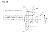
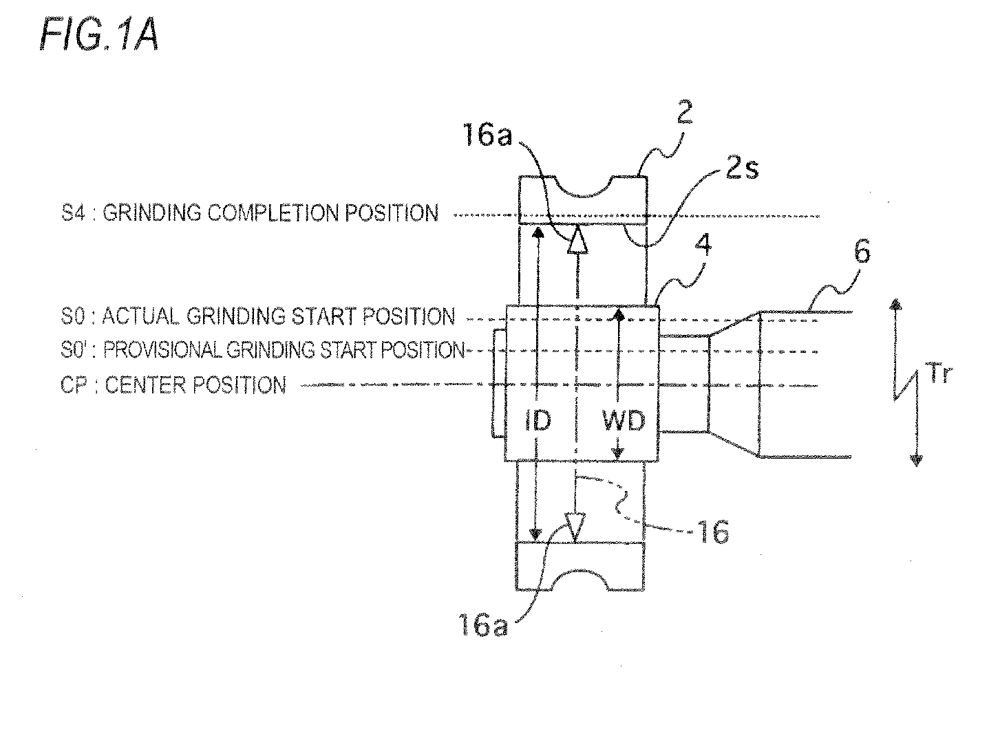
- the calculation of the provisional grinding start position S0' is performed based on the specifications of the first workpiece (inner ring) 2 registered in the workpiece specification database 10 by the arithmetic processing section 12. That is, the provisional grinding start position S0' of the grinding wheel 4 relative to the inner diameter surface 2s of the first workpiece (inner ring) 2 is calculated, with reference to the center position CP of the support shaft 6 supporting the grinding wheel 4, and from the diameter (inner diameter) ID of the first workpiece (inner ring) 2 before it is ground, the diameter WD of the grinding wheel, the fine finish completion position S4 on the workpiece (inner ring) 2 immediately after the grinding, and the actual grinding start position S0 of the grinding wheel 4 relative to each of second and subsequent workpieces (inner rings) 2 before grinding.
- the center position CP of the support shaft 6 supporting the grinding wheel 4 is stored in the arithmetic processing section 12 in advance as information to control the AC servo motor for feed control of the support shaft 6.
- the center position CP of the support shaft 6 supporting the grinding wheel 4 is a position in which a rotational center line of a backing plate (not illustrated) rotatably supporting the workpiece (inner ring) 2 and a center line of the grinding wheel 4.
- the provisional grinding start position S0' is set by the arithmetic processing section 12 based on the calculation which will be described below, in view of a predetermined allowance S ⁇ between the actual grinding start position S0 and the provisional grinding start position S0'.
- the allowance S ⁇ is set in view of an amount of error which may be generated when arranging the grinding wheel 4 to face the inner diameter surface 2s of the first workpiece (inner ring) 2 at the time of starting the grinding (see FIG. 1A ).
- the following 6 factors may be the errors that are taken into account as the allowance S ⁇ .
- the following factors are merely an example, and the technical scope of the present invention is not limited thereto. Other factors may be added as the error amount of the allowance S ⁇ .
- the provisional grinding start position S0' is set to a position relatively largely spaced from the inner diameter surface 2s of the first workpiece (inner ring) 2 before the grinding by the arithmetic processing section 12.
- the arithmetic processing section 12 controls the grinder 8 based on the set data to perform the feed control and the rotation control on the support shaft 6, so that the stop position of the grinding wheel 4 is controlled to be at the provisional grinding start position S0'.
- the grinding wheel 4 is positioned at the provisional grinding start position S0' (P4 in FIG. 2B ).
- the arithmetic processing section 12 performs the grinding on the inner diameter surface 2s of the first workpiece (inner ring) 2 while relatively moving the grinding wheel 4 with respect to the first workpiece (inner ring) 2 from the provisional grinding start position S0' (P5 in FIG. 2B ). Specifically, the grinding on the first workpiece (inner ring) 2 is performed according to a grinding cycle illustrated in FIG. 2C .
- the arithmetic processing section 12 moves (high-speed feed) the grinding wheel 4 from the provisional grinding start position S0' to the high-speed feed completion position S1 (T1 in Fig. 2C ).
- the arithmetic processing section 12 controls the grinder 8 to switch the moving condition of the grinding wheel 4 from the high-speed feed to the rough feed state.
- the rough feed grinding starts while the grinding wheel 4 is moved (rough feed) (T2 in FIG. 2C ).
- the grinding condition of the inner diameter surface 2s of the first workpiece (inner ring) 2 is always detected by the pair of sensing pins 16a of the in-process gauge 16 (T3 in FIG. 2C ). Near the rough feed completion position S2, the gauge signal I from the in-process gauge 16 is output to the arithmetic processing section 12.
- the arithmetic processing section 12 controls the grinder 8 based on the input gauge signal 1 (T4 in FIG. 2C ) to switch the moving condition of the grinding wheel 4 with respect to the first workpiece (inner ring) 2 from the rough feed grinding to the finish feed grinding. Accordingly, the finish feed grinding starts (T5 in FIG. 2C ).
- the grinding condition of the inner diameter surface 2s of the first workpiece (inner ring) 2 is always detected by the pair of sensing pins 16a of the in-process gauge 16 (T6 in FIG. 2C ). Near the finish feed completion position S3, the gauge signal 2 from the in-process gauge 16 is output to the arithmetic processing section 12.
- the arithmetic processing section 12 controls the grinder 8 based on the input gauge signal 2 (T7 in FIG. 2C ) to switch the moving condition of the grinding wheel 4 with respect to the first workpiece (inner ring) 2 from the finish feed grinding to the fine finish feed grinding. Accordingly, the fine finish feed grinding starts (T8 in FIG. 2C ).
- the grinding condition of the inner diameter surface 2s of the first workpiece (inner ring) 2 is always detected by the pair of sensing pins 16a of the in-process gauge 16 (T9 in FIG. 2C ). Near the fine finish feed completion position S4, the gauge signal 3 from the in-process gauge 16 is output to the arithmetic processing section 12.
- the arithmetic processing section 12 controls the grinder 8 based on the input gauge signal 3 (T10 in FIG. 2C ) to feed the grinding wheel 4 back in a direction spaced apart from the inner diameter surface 2s of the first workpiece (inner ring) 2.
- the backward feeding amount is an amount corresponding to S4, and the grinding wheel 4 is spaced apart from the inner diameter surface 2s of the first workpiece (inner ring) 2 by this backward feeding amount (11 in FIG. 2C ).
- the actual grinding start position S0 is fixed by the arithmetic processing section 12 (P6 in FIG. 2B ).
- the above-described fine finish feed grinding may be omitted by using the effect quill bending.
- the backward feeding control of the grinding wheel 4 is performed based on the input of the gauge signal 3.
- the input of the gauge signal 2 is omitted.
- the backward feeding amount is an amount corresponding to S4, and the grinding wheel 4 is moved away from the inner diameter surface 2s of the first workpiece (inner ring) 2 by this back word feeding amount.
- the grinding can be performed on the inner diameter surface 2s of the first workpiece (inner ring) 2 while the grinding wheel 4 is moved relative to the inner diameter surface 2s of the first workpiece (inner ring) 2 at the beginning of the setting from the provisional grinding start position S0'. Then, the actual grinding start position S0 is fixed by moving the grinding wheel 4 away from the inner diameter surface 2s of the first workpiece (inner ring) 2 as much as S4, based on the gauge signal 3 from the in-process gauge 16, near the grinding completion position S4.
- the position of the grinding wheel at the time when the gauge signal is output from the in-process gauge 16 varies slightly for each workpiece 2.
- the gauge signal may be output when the grinding wheel has not yet reached each of the positions S2, S3, S4, or has slightly passed each of the positions S2, S3, S4.
- the output of the gauge signal in the process of moving the grinding wheel toward the positions S2, S3, S4 is described as the output of the gauge signal near each of the positions S2, S3, S4.
- the setting of the positional relationship between the workpiece (inner ring) 2 and the grinding wheel 4 can be automatically performed. Therefore, it is possible to reduce the time required to switch the settings of the workpiece (inner ring) 2, thereby improving the efficiency of the grinding of the workpiece (inner ring) 2.
- the present invention is not limited to the embodiment described above, and various changes cam be made to implement the invention within the scope as defined in the claims.
- the inner ring has been described as the workpiece 2, but the present invention is not limited thereto.
- the technical concept according to the embodiment described above can of course be applied to a grinding of a radially inner surface (e.g., a raceway groove of the outer ring) of the outer ring as the workpiece 2.
Landscapes
- Engineering & Computer Science (AREA)
- Mechanical Engineering (AREA)
- Constituent Portions Of Griding Lathes, Driving, Sensing And Control (AREA)
- Grinding Of Cylindrical And Plane Surfaces (AREA)
Abstract
Description
- The present invention relates to a grinding technique.
- Conventionally, in a process of manufacturing various kinds of workpiece, such as a bearing ring (inner ring, outer ring), grinding on an inner diameter portion of a workpiece (e.g., inner ring) or grinding on a raceway groove of another workpiece (e.g., outer ring) is performed. Various proposals have been made in connection with such a grinding technique (see, e.g., Patent Document 1).
- According to a conventional grinding technique, when setting a positional relationship between a grinding wheel and a workpiece at the time of, for example, switching workpiece settings, the workpiece is set on a spindle, and then a teaching operation is performed in which an infeed shaft is manually operated to bring the grinding wheel provided on the infeed shaft into contact with the workpiece. For example, the teaching operation with respect to the inner ring includes a manual operation of the infeed shaft to a position where the grinding wheel abuts (contacts) an inner diameter surface of the inner ring. Further, the teaching operation with respect to the outer ring includes a manual operation of the infeed shaft to a position where the grinding wheel abuts (contacts) the raceway groove of the outer ring.
- Patent Document 1:
JP 2010-076005 A - However, the teaching operation (contacting operation) described above requires an experience, and workers engaging in the teaching operation are required to have high skill. Depending on an experience level of the worker, the teaching operation may take time, and the time required to switch the workpiece settings may be prolonged. As a result, it may hamper an improvement in efficiency of grinding of the workpiece.
- In addition, in the teaching operation, difference in grinding skill among respective workers may cause an error in the position at which the grinding wheel is brought into contact with the workpiece. Depending on the amount of error, the workpiece may not be ground accurately, which may result in a production of a defective product and a significant deterioration of a yield.
- The present invention has been made to solve the problems described above, and it is an object thereof to provide a grinding technique capable of shortening the time required to switch workpiece settings and capable of grinding a workpiece with high precision by bringing a grinding wheel into contact with the workpiece accurately.
- In order to achieve the above object, according to the present invention, a grinding machine includes a grinding wheel configured to grind a workpiece, and a grinding wheel control system configured to move the grinding wheel relative to the workpiece. The grinding machine includes a first control section configured to calculate and set a provisional grinding start position S0' of the grinding wheel relative to a first workpiece, with a center position of a support shaft supporting the grinding wheel being a reference, and based on a diameter ID of the first workpiece before grinding, a diameter WD of the grinding wheel, a grinding completion position S4 on the first workpiece after the grinding, and an actual grinding start position S0 of the grinding wheel relative to each of second and subsequent workpieces before grinding, a second control section configured to position the grinding wheel at the provisional grinding start position S0' that has been set by the first control section, a third control section configured move the grinding wheel relative to the first workpiece from the provisional grinding start position S0' to grind the first workpiece, and a fourth control section configured to fix the actual grinding start position S0 by moving the grinding wheel away from the first workpiece by a distance corresponding to S4, based on a gauge signal from an in-process gauge near the grinding completion position S4. The first control section is configured to set the provisional grinding start position SO' by a calculation, S0' = ID - WD - S4 - Sα, in view of a predetermined allowance Sα between the actual grinding start position S0 and the provisional grinding start position S0'.
- According to an aspect of the present invention, the in-process gauge is configured to measure the diameter of the first workpiece to detect a grinding condition of the first workpiece. The fourth control section is configured to fix the actual grinding start position S0 by moving the grinding wheel away from the first workpiece by the distance corresponding to S4, based on the gauge signal from the in-process gauge near the grinding completion position S4.
- According to as aspect of the present invention, the allowance Sα is set in view of an error generated when arranging the grinding wheel to face the first workpiece to at the time of starting the grinding.
- According to as aspect of the present invention, when switching between a setting for a grinding of a certain workpiece and a setting for a grinding of a different workpiece, the fourth control section is configured to, in the grinding of the first workpiece at a beginning of the setting, moves the grinding wheel relative to the first workpiece from the provisional grinding start position S0' to grind the first workpiece, and moves the grinding wheel away from the first workpiece by the distance corresponding to S4, based on the gauge signal from the in-process gauge near the grinding completion position S4, to fix the actual grinding start position S0, and in the grinding of each of the second and subsequent workpieces after the switching of the settings, repeat a process of moving the grinding wheel relative to the workpiece from the actual grinding start position S0 to grind the workpiece, and moving the grinding wheel to actual grinding start position S0 based on the gauge signal from the in-process gauge near the grinding completion position S4.
- According to the present invention, a teaching operation of bringing the grinding wheel into contact with the workpiece becomes unnecessary, and the workpiece settings can be performed automatically. Therefore, it is possible to reduce the time required to switch the workpiece settings, and to grind the workpiece with high precision by accurately bringing the grinding wheel into contact with the workpiece. Consequently, according to the present invention, the grinding technique capable of reducing a production a defective product and having superior grinding efficiency can be achieved.
-
-
FIG. 1A is a diagram illustrating a positional relationship between a grinding start position and a grinding completion position in a grinding machine according to an embodiment of the present invention; -
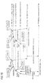
FIG. 1B is a diagram illustrating an example of a grinding cycle for implementing a grinding method according to an embodiment of the present invention; -
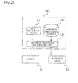
FIG. 2A is a block diagram illustrating a configuration of a grinding wheel control system in a grinding machine according to an embodiment of the present invention; -
FIG. 2B is flowchart illustrating an initial grinding process at the time of switching workpiece settings; and -
Fig. 2C is a flowchart illustrating a subroutine of the grinding cycle. - Hereinafter, a grinding technique according to an embodiment of the present invention will be described with reference to the accompanying drawings.
-
FIGs. 1A and2A illustrate a configuration of a grinding machine for implementing a grinding technique of this embodiment. The grinding machine includes agrinding wheel 4 which performs grinding on aworkpiece 2, and a grinding wheel control system NC which moves thegrinding wheel 4 relative to theworkpiece 2. In this instance, thegrinding wheel 4 is supported by a support shaft (also called as an infeed shaft or a servo shaft) of a quill type, and thesupport shaft 6 is incorporated in thegrinder 8 which is controlled by the grinding wheel control system NC. - The grinding wheel control system NC includes a
workpiece specification database 10 in which specifications required for the grinding ofvarious workpieces 2 are registered in advance, and anarithmetic processing section 12 which executes a given arithmetic processing based on the specifications of the various workpieces registered in theworkpiece specification database 10. Examples of theworkpiece 2 include an inner ring and an outer ring of a bearing. - The specifications of
various workpieces 2 registered in theworkpiece specification database 10 is information required for the grinding of theworkpiece 2. For example, the information including a diameter (inner diameter) ID of theworkpiece 2 before the grinding, and a moving position of thegrinding wheel 4 for the grinding (e.g., a grinding feed position such as a high-speed feed completion position S1, a rough feed completion position S2, a finish feed completion position S3, and a fine finish completion position S4) is used as an example of these specifications. In this instance, the high-speed feed completion position S1 means a range in which thegrinding wheel 4 comes first into contact with theworkpiece 2 at the grinding, in other words, a range of which thegrinding wheel 4 does not in contact with theworkpiece 2. Each of positions S2, S3, S4 indicates a range in which each grinding feed of the rough feed grinding, the finish feed grinding, and the fine finish feed grinding is performed after thegrinding wheel 4 is taught in the workpiece 2 (seeFIG. 1B ). - A computer (not illustrated) for executing various arithmetic processing required for the grinding based on the above-described specifications is installed in the
arithmetic processing section 12. The computer includes a ROM (not illustrated) storing various arithmetic processing programs, a RAM (not illustrated) specifying an operational region for executing the arithmetic processing program, and a CPU (not illustrated) executing the arithmetic processing program in the RAM. - In the
arithmetic processing section 12, the above-described arithmetic processing is executed based the specifications of various workpieces registered in theworkpiece specification database 10, thegrinder 8 is controlled (e.g., feed control or rotation control) based on the arithmetic processing result. Accordingly, thegrinding wheel 4 supported by thesupport shaft 6 can be move relatively to theworkpiece 2 to perform the grinding (each grinding feed of the rough feed grinding, the finish feed grinding, and the fine finish feed grinding) on theworkpiece 2. In this instance, thesupport shaft 6 is feed-controlled or rotation-controlled by, for example, an AC servo motor (not illustrated). Therefore, the movement control of thegrinding wheel 4 to the above-described grinding feed positions S0, S1, S2, S3, S4. - Specifically, based on the specification data associated with the
workpiece 2 matched to a model number which is assigned for everyworkpiece 2, thearithmetic processing section 12 controls thegrinder 8. The model number is input from aninput instruction section 14 which is provided in the grinding wheel control system NC. In this instance, thearithmetic processing section 12 detects a rotational displacement and a revolving speed of an output shaft of the AC servo motor by an encoder (rotation detector) (not illustrated), and compares a current position (coordinates) signal and a target position (coordinates) signal to perform a feedback control (feed control and rotation control) on thesupport shaft 6. - If there is a difference between the current position (coordinates) signal and the target position (coordinates) signal, the
arithmetic processing section 12 moves (rotate) the AC servo motor in a direction to decrease the difference from the target position (coordinates) signal. The above procedure is repeated until it reaches finally a target value, or it belongs to an allowable range, thereby performing the movement control of the grindingwheel 4 to the above-described grinding feed positions S0, S1, S2, S3, S4. - Alternatively, for example, the current position information (coordinates) of the AC servo motor can be recorded digitally. The movement of the
grinding wheel 4 to the grinding feed positions S0, S1, S2, S3, S4 may be controlled so that thegrinding wheel 4 reaches the target value at one time by providing the information with the difference to the target position (coordinates) signal. In this way, it is possible to improve the efficiency of the routine from the switching of the settings of theworkpiece 2 to the grinding. - The grinding condition of the
workpiece 2 is always detected by an in-process gauge 16. When the diameter (inner diameter) ID of theworkpiece 2 becomes a preset value (e.g., a desired finish dimension), a gauge signal indicating the diameter is output from the in-process gauge 16 to the grinding wheel control system NC (specifically, the arithmetic processing section 12). - The in-
process gauge 16 is provided with a pair ofopposite sensing pins 16a, and the grinding condition of theworkpiece 2 can be always detected by setting the pair of sensing pins 16a onto a portion to be ground of theworkpiece 2. In this instance, so as to cancel an effect of eccentricity of theworkpiece 2 during the grinding, it is preferable to set one pair ofsensing pins 16a to measure the diameter (inner diameter) ID of theworkpiece 2. - Further, when the gauge signal is output from the in-process gauge 16 (in other words, when the gauge signal from the in-
process gauge 16 is input to the arithmetic processing section 12), thearithmetic processing section 12 controls thegrinder 8 based on the gauge signal. In this way, the moving condition of thegrinding wheel 4 with respect to the workpiece 2 (specifically, grinding feed including the rough feed grinding, the finish feed grinding, and the fine finish feed grinding) is switched (seeFIG. 1B ). - For example, when the
gauge signal 1 is input during the rough feed, thearithmetic processing section 12 switches the following moving condition (grinding feed) of thegrinding wheel 4 to be the finish feed. Further, for example, when thegauge signal 2 is input during the finish feed, thearithmetic processing section 12 switches the following moving condition (grinding feed) of thegrinding wheel 4 to be the fine finish feed. For example, when thegauge signal 3 is input during the fine finish feed, thearithmetic processing section 12 feeds thegrinding wheel 4 back to the actual grinding start position S0. - In the grinding technique of this embodiment, the operational flow will be described based on detailed configuration. In the operational flow, as one example of the
workpiece 2, the inner ring is used. Further, the portion which is subjected to the grinding is generally an inner diameter surface or an outer diameter surface of theworkpiece 2, for example, but aninner diameter surface 2s of the workpiece (inner ring) 2 is subjected to the grinding as one example. - Further, in the operational flow, in particular, the switching is performed between the setting for the grinding on one
workpiece 2 and the setting for the grinding on anotherworkpiece 2. That is, in the operational flow, the settings are switched among workpieces (inner rings) 2 having different model numbers. Herein, the grinding process before the switching of the settings, that is, aninner diameter surface 2s of the first workpiece (inner ring) 2, will be described. In this instance, the pair ofsensing pins 16a of the in-process gauge 16 are set to measure the inner diameter of the workpiece 2 (inner ring), that is, the diameter ID of theinner diameter surface 2s. - As illustrated in
FIGs. 2A and2B , when a new model number data is input from theinput instruction section 14 to designate the first workpiece (inner ring) 2 (P1 inFIG. 2B ), the diameter (inner diameter) ID of the designated workpiece (inner ring) 2 is determined. Then, the diameter WD of thegrinding wheel 4 is input and designated from the input instruction section 14 (P2 inFIG. 2B ). Accordingly, the grinding wheel control system NC sets the provisional grinding start position SO', at which thegrinding wheel 4 is to be positioned relative to theinner diameter surface 2s of theworkpiece 2, by calculation (P3 inFIG. 2B ). - The calculation of the provisional grinding start position S0' is performed based on the specifications of the first workpiece (inner ring) 2 registered in the
workpiece specification database 10 by thearithmetic processing section 12. That is, the provisional grinding start position S0' of thegrinding wheel 4 relative to theinner diameter surface 2s of the first workpiece (inner ring) 2 is calculated, with reference to the center position CP of thesupport shaft 6 supporting thegrinding wheel 4, and from the diameter (inner diameter) ID of the first workpiece (inner ring) 2 before it is ground, the diameter WD of the grinding wheel, the fine finish completion position S4 on the workpiece (inner ring) 2 immediately after the grinding, and the actual grinding start position S0 of thegrinding wheel 4 relative to each of second and subsequent workpieces (inner rings) 2 before grinding. - Further, the center position CP of the
support shaft 6 supporting thegrinding wheel 4 is stored in thearithmetic processing section 12 in advance as information to control the AC servo motor for feed control of thesupport shaft 6. The center position CP of thesupport shaft 6 supporting thegrinding wheel 4 is a position in which a rotational center line of a backing plate (not illustrated) rotatably supporting the workpiece (inner ring) 2 and a center line of thegrinding wheel 4. - In this embodiment, the provisional grinding start position S0' is set by the
arithmetic processing section 12 based on the calculation which will be described below, in view of a predetermined allowance Sα between the actual grinding start position S0 and the provisional grinding start position S0'. The allowance Sα is set in view of an amount of error which may be generated when arranging thegrinding wheel 4 to face theinner diameter surface 2s of the first workpiece (inner ring) 2 at the time of starting the grinding (seeFIG. 1A ). In this instance, for example, the following 6 factors may be the errors that are taken into account as the allowance Sα. The following factors are merely an example, and the technical scope of the present invention is not limited thereto. Other factors may be added as the error amount of the allowance Sα. - (1) In a case in which the
workpiece 2 is an outer ring, a positional error of a backing plate (not illustrated) rotatably supporting theworkpiece 2. - (2) In a case in which the
workpiece 2 is the outer ring, a dimensional error of an outer diameter of an outer ring groove. - (3) Measurement error of the diameter WD of the
grinding wheel 4. - (4) Error due to an inclination (bending amount) of a quill
type support shaft 6. - (5) In a case in which the
workpiece 2 is held by a pair of shoes, an error due to wearing of the shoes. - (6) In a case in which the
workpiece 2 is held by a pair of shoes, an error in polishing precision of the shoes. - Specifically, the provisional grinding start position S0' is set to a position relatively largely spaced from the
inner diameter surface 2s of the first workpiece (inner ring) 2 before the grinding by thearithmetic processing section 12. Thearithmetic processing section 12 controls thegrinder 8 based on the set data to perform the feed control and the rotation control on thesupport shaft 6, so that the stop position of thegrinding wheel 4 is controlled to be at the provisional grinding start position S0'. Thus, thegrinding wheel 4 is positioned at the provisional grinding start position S0' (P4 inFIG. 2B ). - Next, the
arithmetic processing section 12 performs the grinding on theinner diameter surface 2s of the first workpiece (inner ring) 2 while relatively moving thegrinding wheel 4 with respect to the first workpiece (inner ring) 2 from the provisional grinding start position S0' (P5 inFIG. 2B ). Specifically, the grinding on the first workpiece (inner ring) 2 is performed according to a grinding cycle illustrated inFIG. 2C . - First, as illustrated in
FIGs. 1B and2C , thearithmetic processing section 12 moves (high-speed feed) thegrinding wheel 4 from the provisional grinding start position S0' to the high-speed feed completion position S1 (T1 inFig. 2C ). Next, thearithmetic processing section 12 controls thegrinder 8 to switch the moving condition of thegrinding wheel 4 from the high-speed feed to the rough feed state. After that, in the state in which thegrinding wheel 4 is taught in theinner diameter surface 2s of the first workpiece (inner ring) 2, the rough feed grinding starts while thegrinding wheel 4 is moved (rough feed) (T2 inFIG. 2C ). - While the rough feed grinding is performed, the grinding condition of the
inner diameter surface 2s of the first workpiece (inner ring) 2 is always detected by the pair ofsensing pins 16a of the in-process gauge 16 (T3 inFIG. 2C ). Near the rough feed completion position S2, the gauge signal I from the in-process gauge 16 is output to thearithmetic processing section 12. - The
arithmetic processing section 12 controls thegrinder 8 based on the input gauge signal 1 (T4 inFIG. 2C ) to switch the moving condition of thegrinding wheel 4 with respect to the first workpiece (inner ring) 2 from the rough feed grinding to the finish feed grinding. Accordingly, the finish feed grinding starts (T5 inFIG. 2C ). - While the finish feed grinding is performed, the grinding condition of the
inner diameter surface 2s of the first workpiece (inner ring) 2 is always detected by the pair ofsensing pins 16a of the in-process gauge 16 (T6 inFIG. 2C ). Near the finish feed completion position S3, thegauge signal 2 from the in-process gauge 16 is output to thearithmetic processing section 12. - The
arithmetic processing section 12 controls thegrinder 8 based on the input gauge signal 2 (T7 inFIG. 2C ) to switch the moving condition of thegrinding wheel 4 with respect to the first workpiece (inner ring) 2 from the finish feed grinding to the fine finish feed grinding. Accordingly, the fine finish feed grinding starts (T8 inFIG. 2C ). - While the fine finish feed grinding is performed, the grinding condition of the
inner diameter surface 2s of the first workpiece (inner ring) 2 is always detected by the pair ofsensing pins 16a of the in-process gauge 16 (T9 inFIG. 2C ). Near the fine finish feed completion position S4, thegauge signal 3 from the in-process gauge 16 is output to thearithmetic processing section 12. - The
arithmetic processing section 12 controls thegrinder 8 based on the input gauge signal 3 (T10 inFIG. 2C ) to feed thegrinding wheel 4 back in a direction spaced apart from theinner diameter surface 2s of the first workpiece (inner ring) 2. The backward feeding amount is an amount corresponding to S4, and thegrinding wheel 4 is spaced apart from theinner diameter surface 2s of the first workpiece (inner ring) 2 by this backward feeding amount (11 inFIG. 2C ). - Therefore, in the grinding process of the original set illustrated in
FIG. 2B , the actual grinding start position S0 is fixed by the arithmetic processing section 12 (P6 inFIG. 2B ). The above-described fine finish feed grinding may be omitted by using the effect quill bending. In this case also, the backward feeding control of thegrinding wheel 4 is performed based on the input of thegauge signal 3. In this case, the input of thegauge signal 2 is omitted. The backward feeding amount is an amount corresponding to S4, and thegrinding wheel 4 is moved away from theinner diameter surface 2s of the first workpiece (inner ring) 2 by this back word feeding amount. - Based on the fixed actual grinding start position S0, and in view of the predetermined allowance Sα descriebd above, the
arithmetic processing section 12 sets the provisional grinding start position S0' by the following equation:
- In this way, according to the grinding technique of this embodiment, the grinding can be performed on the
inner diameter surface 2s of the first workpiece (inner ring) 2 while thegrinding wheel 4 is moved relative to theinner diameter surface 2s of the first workpiece (inner ring) 2 at the beginning of the setting from the provisional grinding start position S0'. Then, the actual grinding start position S0 is fixed by moving thegrinding wheel 4 away from theinner diameter surface 2s of the first workpiece (inner ring) 2 as much as S4, based on thegauge signal 3 from the in-process gauge 16, near the grinding completion position S4. - When grinding the
inner diameter surface 2s of each of second and subsequent workpieces (inner rings) 2 after the settings have been switched, the grinding is performed on theinner diameter surface 2s of the workpiece (inner ring) 2 while thegrinding wheel 4 is moved relative to theinner diameter surface 2s of the workpiece (inner ring) 2 from the actual grinding start position S0. The grinding process of moving thegrinding wheel 4 to the actual grinding start position S0, based on thegauge signal 3 from the in-process gauge 16, near the grinding completion position S4 is again repeated. - There is an individual difference in the outer diameter of the
workpiece 2, and there is also light variation in the position at which theworkpiece 2 is fixed to the grinding section. Due to this, the position of the grinding wheel at the time when the gauge signal is output from the in-process gauge 16 varies slightly for eachworkpiece 2. The gauge signal may be output when the grinding wheel has not yet reached each of the positions S2, S3, S4, or has slightly passed each of the positions S2, S3, S4. In the present description, the output of the gauge signal in the process of moving the grinding wheel toward the positions S2, S3, S4 is described as the output of the gauge signal near each of the positions S2, S3, S4. - According to this embodiment, since the above-described teaching operation (contacting operation) is not necessary, the setting of the positional relationship between the workpiece (inner ring) 2 and the
grinding wheel 4 can be automatically performed. Therefore, it is possible to reduce the time required to switch the settings of the workpiece (inner ring) 2, thereby improving the efficiency of the grinding of the workpiece (inner ring) 2. - In this instance, even if there are relative merits in grinding skills of workers working on switching of the settings, it is possible to accurately teach the
grinding wheel 4 in the workpiece (inner ring) 2. Therefore, the workpiece (inner ring) 2 is ground with high precision, and generation of a defective product can be decreased. As a result, a yield can be remarkably improved. - The present invention is not limited to the embodiment described above, and various changes cam be made to implement the invention within the scope as defined in the claims. In the embodiment described above, the inner ring has been described as the
workpiece 2, but the present invention is not limited thereto. The technical concept according to the embodiment described above can of course be applied to a grinding of a radially inner surface (e.g., a raceway groove of the outer ring) of the outer ring as theworkpiece 2. - The present application is based on Japanese Patent Application No.
2011-148538 filed on July 4, 2011 -
- 2:
- workpiece (inner ring, outer ring)
- 4:
- grinding wheel
- 6:
- support shaft (infeed shaft, servo shaft)
- CP:
- center position (center) of support shaft
- ID:
- diameter (inner diameter) of workpiece before grinding
- WD:
- diameter of grinding wheel
- S4:
- grinding completion position
- S0:
- actual grinding start position
- S0':
- provisional grinding start position
- Sα:
- allowance
Claims (8)
- A grinding machine comprising a grinding wheel configured to grind a workpiece, and a grinding wheel control system configured to move the grinding wheel relative to the workpiece, the grinding machine comprising:a first control section configured to calculate and set a provisional grinding start position S0' of the grinding wheel relative to a first workpiece, with a center position of a support shaft supporting the grinding wheel being a reference, and based on a diameter ID of the first workpiece before grinding, a diameter WD of the grinding wheel, a grinding completion position S4 on the first workpiece after the grinding, and an actual grinding start position S0 of the grinding wheel relative to each of second and subsequent workpieces before grinding;a second control section configured to position the grinding wheel at the provisional grinding start position S0' that has been set by the first control section;a third control section configured move the grinding wheel relative to the first workpiece from the provisional grinding start position S0' to grind the first workpiece; anda fourth control section configured to fix the actual grinding start position S0 by moving the grinding wheel away from the first workpiece by a distance corresponding to S4, based on a gauge signal from an in-process gauge near the grinding completion position S4,wherein the first control section is configured to set the provisional grinding start position S0' by a calculation,
 in view of a predetermined allowance Su between the actual grinding start position S0 and the provisional grinding start position S0'.
 - The grinding machine according to claim 1, wherein the in-process gauge is configured to measure the diameter of the first workpiece to detect a grinding condition of the first workpiece, and
the fourth control section is configured to fix the actual grinding start position S0 by moving the grinding wheel away from the first workpiece by the distance corresponding to S4, based on the gauge signal from the in-process gauge near the grinding completion position S4. - The grinding machine according to claim 1 or 2, wherein the allowance Sα is set in view of an error generated when arranging the grinding wheel to face the first workpiece to at the time of starting the grinding.
- The grinding machine according to any one of claims 1 to 3, wherein, when switching between a setting for a grinding of a certain workpiece and a setting for a grinding of a different workpiece, the fourth control section is configured to,
in the grinding of the first workpiece at a beginning of the setting, moves the grinding wheel relative to the first workpiece from the provisional grinding start position S0' to grind the first workpiece, and moves the grinding wheel away from the first workpiece by the distance corresponding to S4, based on the gauge signal from the in-process gauge near the grinding completion position S4, to fix the actual grinding start position S0, and
in the grinding of each of the second and subsequent workpieces after the switching of the settings, repeat a process of moving the grinding wheel relative to the workpiece from the actual grinding start position S0 to grind the workpiece, and moving the grinding wheel to actual grinding start position S0 based on the gauge signal from the in-process gauge near the grinding completion position S4. - A grinding method using a grinding machine including a grinding wheel configured to grind a workpiece and a grinding wheel control system configured to move the grinding wheel relative to the workpiece, the grinding method comprising:a first step of calculating and setting a provisional grinding start position S0' of the grinding wheel relative to a first workpiece, with a center position of a support shaft supporting the grinding wheel being a reference, and based on a diameter ID of the first workpiece before grinding, a diameter WD of the grinding wheel, a grinding completion position S4 on the first workpiece after the grinding, and an actual grinding start position S0 of the grinding wheel relative to each of second and subsequent workpieces before grinding;a second step of positioning the grinding wheel at the provisional grinding start position S0' that has been set in the first process;a third step of moving the grinding wheel relative to the first workpiece from the provisional grinding start position S0' to grind the first workpiece; anda fourth step of fixing the actual grinding start position S0 by moving the grinding wheel away from the first workpiece by a distance corresponding to S4 near the grinding completion position S4,wherein in the first step, the provisional grinding start position S0' is set by a calculation,

in view of a predetermined allowance Sα between the actual grinding start position S0 and the provisional grinding start position S0'. - The grinding method according to claim 5, wherein the diameter of the first workpiece is measured by an in-process gauge to detect a grinding condition of the first workpiece, and
in the fourth step, the actual grinding start position S0 is fixed by moving the grinding wheel away from the first workpiece by the distance corresponding to S4, based on a gauge signal from the in-process gauge near the grinding completion position S4. - The grinding method according to claim 5 or 6, wherein the allowance Sα is set in view of an error generated when arranging the grinding wheel to face the first workpiece at the time of starting the grinding.
- The grinding method according to any one of claims 5 to 7, wherein, when switching between a setting for a grinding of a certain workpiece and a setting for a grinding of a different workpiece, in the fourth step,
in the grinding of the first workpiece at a beginning of the setting, the grinding wheel is moved relative to the first workpiece from the provisional grinding start position S0' to grind the first workpiece, and the grinding wheel is moved away from the first workpiece by the distance corresponding to S4, based on the gauge signal from the in-process gauge near the grinding completion position S4, to fix the actual grinding start position S0, and
in the grinding of each of the second and subsequent workpieces after the switching of the settings, a process of moving the grinding wheel relative to the workpiece from the actual grinding start position S0 to grind the workpiece, and moving the grinding wheel to actual grinding start position S0 based on the gauge signal from the in-process gauge near the grinding completion position S4 is repeated.
Applications Claiming Priority (2)
| Application Number | Priority Date | Filing Date | Title |
|---|---|---|---|
| JP2011148538A JP5729178B2 (en) | 2011-07-04 | 2011-07-04 | Grinding machine and grinding method |
| PCT/JP2012/066076 WO2013005590A1 (en) | 2011-07-04 | 2012-06-22 | Grinding disc and grinding method |
Publications (2)
| Publication Number | Publication Date |
|---|---|
| EP2730372A1 true EP2730372A1 (en) | 2014-05-14 |
| EP2730372A4 EP2730372A4 (en) | 2014-12-24 |
Family
ID=47436946
Family Applications (1)
| Application Number | Title | Priority Date | Filing Date |
|---|---|---|---|
| EP12807325.1A Withdrawn EP2730372A4 (en) | 2011-07-04 | 2012-06-22 | Grinding disc and grinding method |
Country Status (6)
| Country | Link |
|---|---|
| US (1) | US9050703B2 (en) |
| EP (1) | EP2730372A4 (en) |
| JP (1) | JP5729178B2 (en) |
| KR (1) | KR101503616B1 (en) |
| CN (1) | CN103052470A (en) |
| WO (1) | WO2013005590A1 (en) |
Families Citing this family (6)
| Publication number | Priority date | Publication date | Assignee | Title |
|---|---|---|---|---|
| JP5708324B2 (en) * | 2011-07-11 | 2015-04-30 | 日本精工株式会社 | Grinding machine and grinding method |
| KR102574589B1 (en) * | 2016-07-01 | 2023-09-06 | 남양넥스모 주식회사 | Apparatus of grinding for works and control method thereof |
| CN106217154B (en) * | 2016-07-01 | 2018-04-20 | 哈尔滨汽轮机厂有限责任公司 | A kind of accurate method for grinding of half a coupler working face |
| CN106272072B (en) * | 2016-08-29 | 2019-05-31 | 佛山市新鹏机器人技术有限公司 | The polishing position point measuring method and device of toilet articles |
| EP4252964A4 (en) * | 2020-12-04 | 2024-10-16 | Metrol Co., Ltd. | AUTOMATED GRINDING SYSTEM |
| CN114211328A (en) * | 2021-12-09 | 2022-03-22 | 技感半导体设备(南通)有限公司 | Grinding spindle coordinate measuring method |
Family Cites Families (19)
| Publication number | Priority date | Publication date | Assignee | Title |
|---|---|---|---|---|
| US2963829A (en) * | 1955-12-09 | 1960-12-13 | Hoern & Dilts Inc | Grinding machines |
| US3156075A (en) * | 1962-01-02 | 1964-11-10 | Timken Roller Bearing Co | Gaging device for work grinders |
| US4048764A (en) * | 1973-08-06 | 1977-09-20 | Supfina Maschinenfabrik Hentzen Kg | Method for micro-finish machining of compound, circular arc-shaped profiled surfaces in annular workpieces |
| JPH06262498A (en) * | 1993-03-18 | 1994-09-20 | Toyoda Mach Works Ltd | Grinding method |
| US5562526A (en) * | 1993-03-29 | 1996-10-08 | Toyoda Koki Kabushiki Kaisha | Method and apparatus for grinding a workpiece |
| JP2000094279A (en) * | 1998-09-17 | 2000-04-04 | Think Laboratory Co Ltd | Grinding wheel polishing method and grinding wheel replacement timing detection method |
| JP2004017194A (en) * | 2002-06-14 | 2004-01-22 | Okamoto Machine Tool Works Ltd | Grinding device and method for automatically making grinding wheel approach work using the same |
| KR20040048034A (en) | 2002-12-02 | 2004-06-07 | 삼성전자주식회사 | Cooking apparatus and method thereof |
| CN100526007C (en) * | 2004-12-10 | 2009-08-12 | 中原工学院 | Process for grinding tumbler bearing bore and its specified clamp apparatus |
| JP2009184063A (en) * | 2008-02-06 | 2009-08-20 | Jtekt Corp | Grinding machine and grinding method |
| JP5277692B2 (en) * | 2008-03-31 | 2013-08-28 | 株式会社ジェイテクト | Post-process sizing controller |
| US20100022167A1 (en) * | 2008-07-25 | 2010-01-28 | Supfina Grieshaber Gmbh & Co. Kg | Superfinish Machine with an Endless Polishing Band and Method for Operating a Superfinish Machine |
| JP2010076005A (en) | 2008-09-24 | 2010-04-08 | Jtekt Corp | Method of setting up machine tool |
| JP5395570B2 (en) * | 2009-08-25 | 2014-01-22 | コマツNtc株式会社 | Cylindrical grinding method and apparatus |
| JP5416527B2 (en) * | 2009-09-29 | 2014-02-12 | 株式会社太陽工機 | Grinder |
| US8517797B2 (en) * | 2009-10-28 | 2013-08-27 | Jtekt Corporation | Grinding machine and grinding method |
| JP2011148538A (en) | 2010-01-25 | 2011-08-04 | Yushin:Kk | Film-like non-returning nozzle and flexible packaging bag |
| JP5573459B2 (en) * | 2010-07-27 | 2014-08-20 | 株式会社ジェイテクト | Grinding method and grinding machine |
| JP5708324B2 (en) * | 2011-07-11 | 2015-04-30 | 日本精工株式会社 | Grinding machine and grinding method |
-
2011
- 2011-07-04 JP JP2011148538A patent/JP5729178B2/en active Active
-
2012
- 2012-06-22 CN CN2012800005894A patent/CN103052470A/en active Pending
- 2012-06-22 EP EP12807325.1A patent/EP2730372A4/en not_active Withdrawn
- 2012-06-22 WO PCT/JP2012/066076 patent/WO2013005590A1/en not_active Ceased
- 2012-06-22 KR KR1020137005926A patent/KR101503616B1/en not_active Expired - Fee Related
- 2012-06-22 US US14/130,542 patent/US9050703B2/en active Active
Non-Patent Citations (2)
| Title |
|---|
| No further relevant documents disclosed * |
| See also references of WO2013005590A1 * |
Also Published As
| Publication number | Publication date |
|---|---|
| EP2730372A4 (en) | 2014-12-24 |
| WO2013005590A1 (en) | 2013-01-10 |
| US20140127972A1 (en) | 2014-05-08 |
| CN103052470A (en) | 2013-04-17 |
| US9050703B2 (en) | 2015-06-09 |
| KR101503616B1 (en) | 2015-03-18 |
| KR20130075768A (en) | 2013-07-05 |
| JP2013013971A (en) | 2013-01-24 |
| JP5729178B2 (en) | 2015-06-03 |
Similar Documents
| Publication | Publication Date | Title |
|---|---|---|
| EP2732918B1 (en) | Grinding plate and grinding method | |
| CN103506915B (en) | Abrasive machining device | |
| US9050703B2 (en) | Grinding machine and grinding method | |
| EP2921259B1 (en) | Grinding wheel truing method and grinding machine | |
| CN104853880A (en) | Grinding processing method | |
| US9849547B2 (en) | Manufacturing apparatus and manufacturing method for manufacturing less unbalanced blower blade | |
| JP5688280B2 (en) | Edge processing equipment for flat plate workpieces | |
| JP7172636B2 (en) | Machine tool maintenance support device and machine tool system | |
| EP1736278B1 (en) | Grinding method | |
| CN103192321B (en) | A kind of taper error self-checking device of centerless internal grinder | |
| JPH04348869A (en) | Correction device for angular grinding wheel | |
| JP2020114614A (en) | Surface roughness estimation device and machine tool system | |
| JPH10328984A (en) | Centerless grinding method and centerless grinding machine | |
| CN115971979A (en) | A roll grinding debugging system and debugging method | |
| CN121014982B (en) | Shoe edge polishing equipment and contour calibration method and device thereof | |
| JP3350784B2 (en) | Cam grinding machine, cam grinding method using this grinding machine, and method for creating final cam grinding information in this grinding machine | |
| KR102574589B1 (en) | Apparatus of grinding for works and control method thereof | |
| JP5133770B2 (en) | Workpiece grinding method using a grinding machine | |
| JPS61182770A (en) | Work method of surface grinding machine | |
| JP2022083623A (en) | Operation method of machine tool and machine tool | |
| JP2017127926A (en) | Grindstone correction device, machine tool having the same and grindstone correction method | |
| JP2017127925A (en) | Honing machine |
Legal Events
| Date | Code | Title | Description |
|---|---|---|---|
| PUAI | Public reference made under article 153(3) epc to a published international application that has entered the european phase |
Free format text: ORIGINAL CODE: 0009012 |
|
| 17P | Request for examination filed |
Effective date: 20140103 |
|
| AK | Designated contracting states |
Kind code of ref document: A1 Designated state(s): AL AT BE BG CH CY CZ DE DK EE ES FI FR GB GR HR HU IE IS IT LI LT LU LV MC MK MT NL NO PL PT RO RS SE SI SK SM TR |
|
| DAX | Request for extension of the european patent (deleted) | ||
| A4 | Supplementary search report drawn up and despatched |
Effective date: 20141124 |
|
| RIC1 | Information provided on ipc code assigned before grant |
Ipc: B24B 49/10 20060101ALI20141118BHEP Ipc: B24B 5/00 20060101ALI20141118BHEP Ipc: B24B 51/00 20060101ALI20141118BHEP Ipc: B24B 49/02 20060101AFI20141118BHEP |
|
| 17Q | First examination report despatched |
Effective date: 20151221 |
|
| STAA | Information on the status of an ep patent application or granted ep patent |
Free format text: STATUS: THE APPLICATION IS DEEMED TO BE WITHDRAWN |
|
| 18D | Application deemed to be withdrawn |
Effective date: 20160105 |