JP5729178B2 - Grinding machine and grinding method - Google Patents
Grinding machine and grinding method Download PDFInfo
- Publication number
- JP5729178B2 JP5729178B2 JP2011148538A JP2011148538A JP5729178B2 JP 5729178 B2 JP5729178 B2 JP 5729178B2 JP 2011148538 A JP2011148538 A JP 2011148538A JP 2011148538 A JP2011148538 A JP 2011148538A JP 5729178 B2 JP5729178 B2 JP 5729178B2
- Authority
- JP
- Japan
- Prior art keywords
- grinding
- workpiece
- start position
- gauge
- wheel
- Prior art date
- Legal status (The legal status is an assumption and is not a legal conclusion. Google has not performed a legal analysis and makes no representation as to the accuracy of the status listed.)
- Active
Links
Images

Classifications
-
- B—PERFORMING OPERATIONS; TRANSPORTING
- B24—GRINDING; POLISHING
- B24B—MACHINES, DEVICES, OR PROCESSES FOR GRINDING OR POLISHING; DRESSING OR CONDITIONING OF ABRADING SURFACES; FEEDING OF GRINDING, POLISHING, OR LAPPING AGENTS
- B24B51/00—Arrangements for automatic control of a series of individual steps in grinding a workpiece
-
- B—PERFORMING OPERATIONS; TRANSPORTING
- B24—GRINDING; POLISHING
- B24B—MACHINES, DEVICES, OR PROCESSES FOR GRINDING OR POLISHING; DRESSING OR CONDITIONING OF ABRADING SURFACES; FEEDING OF GRINDING, POLISHING, OR LAPPING AGENTS
- B24B49/00—Measuring or gauging equipment for controlling the feed movement of the grinding tool or work; Arrangements of indicating or measuring equipment, e.g. for indicating the start of the grinding operation
- B24B49/02—Measuring or gauging equipment for controlling the feed movement of the grinding tool or work; Arrangements of indicating or measuring equipment, e.g. for indicating the start of the grinding operation according to the instantaneous size and required size of the workpiece acted upon, the measuring or gauging being continuous or intermittent
-
- B—PERFORMING OPERATIONS; TRANSPORTING
- B24—GRINDING; POLISHING
- B24B—MACHINES, DEVICES, OR PROCESSES FOR GRINDING OR POLISHING; DRESSING OR CONDITIONING OF ABRADING SURFACES; FEEDING OF GRINDING, POLISHING, OR LAPPING AGENTS
- B24B49/00—Measuring or gauging equipment for controlling the feed movement of the grinding tool or work; Arrangements of indicating or measuring equipment, e.g. for indicating the start of the grinding operation
- B24B49/10—Measuring or gauging equipment for controlling the feed movement of the grinding tool or work; Arrangements of indicating or measuring equipment, e.g. for indicating the start of the grinding operation involving electrical means
-
- B—PERFORMING OPERATIONS; TRANSPORTING
- B24—GRINDING; POLISHING
- B24B—MACHINES, DEVICES, OR PROCESSES FOR GRINDING OR POLISHING; DRESSING OR CONDITIONING OF ABRADING SURFACES; FEEDING OF GRINDING, POLISHING, OR LAPPING AGENTS
- B24B5/00—Machines or devices designed for grinding surfaces of revolution on work, including those which also grind adjacent plane surfaces; Accessories therefor
Description
本発明は、ワークのセット替えに際し、ティーチングレス化を実現することで、セット替えに要する時間の短縮化を図ると共に、不良品の発生を無くし、一発で良品を出すことを可能にした研削加工技術に関する。 The present invention realizes the teaching-less operation when changing workpieces, shortening the time required for changing the workpieces, eliminating the occurrence of defective products, and enabling the production of non-defective products in a single shot. It relates to processing technology.
従来、例えば軸受の軌道輪(内輪、外輪)などの各種ワークを製造する工程では、あるワーク(例えば、内輪)の内径に対する研削加工や、他のワーク(例えば、外輪)の軌道溝に対する研削加工が行われており、そのための研削加工技術について種々の提案がされている(例えば、特許文献1参照)。 Conventionally, in the process of manufacturing various workpieces such as bearing rings (inner rings, outer rings) of a bearing, for example, grinding processing for an inner diameter of a certain workpiece (for example, inner ring) and grinding processing for a raceway groove of another workpiece (for example, outer ring). Various proposals have been made regarding the grinding technique for that purpose (see, for example, Patent Document 1).
この場合、例えばワークのセット替えに際し、砥石とワーク(内輪、外輪)との位置関係をセットする場合、従来の研削加工技術では、主軸にワークをセットした後、切込軸を手動操作し、その切込軸に設けられている砥石をワークに当て込むティーチング作業が行われている。例えば、内輪に対するティーチング作業では、砥石が内輪の内径面に当たる(接触する)位置まで切込軸を手動操作したり、外輪に対するティーチング作業では、砥石が外輪の軌道溝に当たる(接触する)位置まで切込軸を手動操作している。 In this case, for example, when setting the positional relationship between the grindstone and the workpiece (inner ring, outer ring) when changing the workpiece, in the conventional grinding technology, after setting the workpiece on the spindle, manually operating the cutting shaft, Teaching work is performed in which a grindstone provided on the cutting shaft is applied to a workpiece. For example, in teaching work on the inner ring, the cutting shaft is manually operated to a position where the grindstone hits (contacts) the inner ring surface of the inner ring, and in teaching work on the outer ring, cuts to the position where the grindstone hits (contacts) the raceway groove of the outer ring. The telescoping shaft is manually operated.
ところで、上記したティーチング作業(当て込み作業)は、熟練を要するため、これに従事する作業者には、研削加工に対する高いスキルが要求されている。このため、熟練の程度によっては、ティーチング作業に時間がかかり、ワークのセット替えに要する時間が長期化し、その結果、ワークに対する研削加工の効率化を図ることが困難になってしまう虞がある。 By the way, since the above-described teaching work (applying work) requires skill, a worker who is engaged in this work is required to have a high skill for grinding. For this reason, depending on the level of skill, it takes time for teaching work, and the time required for changing the workpiece becomes longer, and as a result, it may become difficult to improve the efficiency of grinding for the workpiece.
また、上記したティーチング作業(当て込み作業)では、これに従事する作業者毎の研削加工に対するスキルの違いから、ワークに対する砥石の当て込み位置に誤差が生じる場合がある。そうなると、その誤差の程度によっては、当該ワークに対して精度よく研削加工を行うことができなくなり、その結果、不良品が発生し、歩留まりが著しく低下してしまう虞がある。 Moreover, in the above-described teaching work (putting work), there is a case where an error occurs in the grindstone hitting position with respect to the workpiece due to a difference in the skill with respect to the grinding process for each worker engaged in the teaching work. Then, depending on the degree of the error, the workpiece cannot be accurately ground, resulting in a defective product and a significant decrease in yield.
本発明は、このような問題を解決するためになされており、その目的は、砥石をワークに当て込むティーチング作業を不要とし、ワークのセット替えを自動的に行えるようにすることで、ワークのセット替えに要する時間の短縮化を図ることを可能にすると共に、ワークに対して砥石を正確に当て込むことで当該ワークを精度よく研削加工し、不良品の発生を完全に無くすることを可能にする研削加工効率に優れた研削加工技術を提供することにある。 The present invention has been made in order to solve such a problem, and the object of the present invention is to eliminate the need for teaching work for applying a grindstone to a work and to automatically change the work. It is possible to shorten the time required for changing the set and to accurately grind the workpiece by accurately applying the grindstone to the workpiece, and eliminate the occurrence of defective products completely. It is to provide a grinding technique with excellent grinding efficiency.
このような目的を達成するために、本発明は、ワークの内径面に研削加工を施す砥石と、砥石を前記ワークに対して相対的に移動させる砥石制御システムとを有する研削加工盤であって、砥石を支持する支持軸のセンター位置を基準に、研削加工前の最初のワークの直径をID、前記砥石の直径をWD、研削加工後の最初のワークの研削完了位置をS4、研削加工前の2番目以降の各ワークに対する前記砥石の実際の研削開始位置をS0とし、前記最初のワークに対する前記砥石の仮の研削開始位置S0′を演算によって設定する第1手段(工程)と、前記第1手段で設定された前記仮の研削開始位置S0′に前記砥石を位置決めする第2手段(工程)と、前記仮の研削開始位置S0′から前記砥石を前記最初のワークに対して相対移動させながら、当該最初のワークに研削加工を実行する第3手段(工程)と、前記研削加工が前記研削完了位置S4近傍で、インプロセスゲージからのゲージ信号に基づいて、実際の研削開始位置S0を確定する第4手(工程)段とを備えており、前記第1手段(工程)において、前記仮の研削開始位置S0′は、研削加工前の前記最初のワークの直径IDから前記砥石の直径WDまでの間で、研削加工開始時に前記砥石を最初のワークの内径面に対向配置させた際に生じる誤差量を考慮して設定される余裕量Sαによって設定され、
前記第4手段(工程)は、前記インプロセスゲージによって前記最初のワークの直径を計測することで、当該最初のワークの研削加工状態が検出されており、研削加工が研削完了位置S4近傍で、前記インプロセスゲージからのゲージ信号に基づいて、実際の研削開始位置S0を確定される。
本発明では、あるワークに対する研削加工のためのセットと、他のワークに対する研削加工のためのセットとの切り替えにおいて、前記セット替え当初の最初のワークに対する研削加工では、前記仮の研削開始位置S0′から前記砥石を最初のワークに対して相対移動させながら、当該最初のワークに研削加工を実行し、研削加工が研削完了位置S4近傍で、インプロセスゲージからのゲージ信号に基づいて、実際の研削開始位置S0を確定させ、前記セット替え後の2番目以降の各ワークに対する研削加工では、実際の研削開始位置S0から砥石をワークに対して相対移動させながら、当該ワークに研削加工を実行し、研削加工が研削完了位置S4近傍で、前記インプロセスゲージからのゲージ信号に基づいて、前記砥石を、実際の研削開始位置S0まで移動させるプロセスが繰り返される。
To achieve the above object, the present invention provides a grinding machine having a grinding wheel for performing grinding on the inner diameter surface of the workpiece, and a grinding wheel control system for relatively moving the grinding wheel relative to the workpiece , based on the center position of the support shaft supporting the grinding wheel, the diameter of the first workpiece before grinding ID, the diameter of the grinding wheel WD, the first grinding completion position to S4 in the workpiece after grinding, grinding before the actual grinding start position and S0, first means for setting through calculation the first provisional grinding start position of the grinding wheel relative to the workpiece S0 'of the grinding wheel with respect to the second and subsequent each work (step), the first 'and the second means for positioning the grinding wheel on (step), the grinding start position of the temporary S0' the grinding start position of the provisional S0 set by 1 unit by relatively moving the grinding wheel relative to the first workpiece from Reluctant, and third means for performing a grinding on the first workpiece (step), in the grinding said grinding completion position S4 vicinity, based on the gauge signal from the in-process gauge, the actual grinding start position S0 fourth hand to confirm and a (step) stage, said first means in the (step), the grinding start position of the temporary S0 ', the diameter of the grinding wheel from the first workpiece diameter ID before grinding Is set by a margin amount Sα that is set in consideration of the amount of error that occurs when the grindstone is placed opposite to the inner diameter surface of the first workpiece at the start of grinding, up to WD,
The fourth means (step) measures the diameter of the first workpiece by the in-process gauge so that the grinding state of the first workpiece is detected, and the grinding is performed near the grinding completion position S4. Based on the gauge signal from the in-process gauge, the actual grinding start position S0 is determined.
In the present invention, in switching between a set for grinding a workpiece and a set for grinding another workpiece, in the grinding for the first workpiece at the beginning of the set change, the temporary grinding start position S0 is set. The grindstone is moved relative to the first workpiece while the grinding wheel is moved relative to the first workpiece, and grinding is performed on the first workpiece in the vicinity of the grinding completion position S4 based on the gauge signal from the in-process gauge. In the grinding process for the second and subsequent workpieces after the set change, the grinding start position S0 is determined, and the workpiece is ground while moving the grindstone relative to the workpiece from the actual grinding start position S0. In the vicinity of the grinding completion position S4, the grinding wheel is actually opened based on the gauge signal from the in-process gauge. Process for moving to the position S0 is repeated.
本発明によれば、砥石をワークに当て込むティーチング作業を不要とし、ワークのセット替えを自動的に行えるようにすることで、ワークのセット替えに要する時間の短縮化を図ることを可能にすると共に、ワークに対して砥石を正確に当て込むことで当該ワークを精度よく研削加工し、不良品の発生を完全に無くすることを可能にする研削加工効率に優れた研削加工技術を実現することができる。 According to the present invention, it is possible to shorten the time required for changing the workpiece by eliminating the need for teaching work for applying the grindstone to the workpiece and automatically changing the workpiece. At the same time, by accurately applying the grinding stone to the workpiece, the workpiece can be accurately ground, and the grinding technology with excellent grinding efficiency can be realized to completely eliminate the occurrence of defective products. Can do.
以下、本発明の一実施形態に係る研削加工技術について添付図面を参照して説明する。
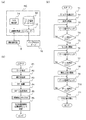
図1(a)及び図2(a)には、本実施形態の研削加工技術を実現するための研削加工盤の構成が示されており、研削加工盤は、ワーク2に研削加工を施す砥石4と、砥石4をワーク2に対して相対的に移動させる砥石制御システムNCとを有している。この場合、砥石4は、クイルタイプの支持軸6(切込軸、サーボ軸ともいう)に支持されており、支持軸6は、砥石制御システムNCによって制御される研削盤本体8に組み込まれている。
Hereinafter, a grinding technique according to an embodiment of the present invention will be described with reference to the accompanying drawings.
FIG. 1A and FIG. 2A show the configuration of a grinding machine for realizing the grinding technique of this embodiment. The grinding machine grinds the
砥石制御システムNCは、各種ワーク2の研削加工に必要な緒元が予め登録されたワーク諸元データベース10と、当該ワーク諸元データベース10に登録された各種ワークの諸元に基づいて、所定の演算処理を実行する演算処理部12とを有している。なお、ワーク2としては、例えば軸受の内輪や外輪を想定することができる。
The grindstone control system NC is based on a
ワーク諸元データベース10に登録された各種ワーク2の諸元としては、当該ワーク2の研削加工に必要な情報が該当する。例えば、研削加工前のワーク2の直径(内径)IDや、研削加工において砥石4を移動させる位置(例えば、急速送り完了位置S1、粗送り完了位置S2、仕上送り完了位置S3、精仕上送り完了位置S4などの研削送り位置)などの情報を想定することができる。なお、急速送り完了位置S1とは、研削加工に際し、砥石4が初めてワーク2に当るまでの範囲、換言すると、砥石4をワーク2に当てない範囲を指し、それ以降の各位置S2,S3,S4は、砥石4がワーク2に当て込まれ、粗送り研削、仕上送り研削、精仕上送り研削の各研削送りが実行されるまでの範囲を指す(図1(b)参照)。
Information necessary for grinding the
演算処理部12には、上記した諸元に基づいて、研削加工に必要な各種の演算処理を実行するためのコンピュータ(図示しない)が内蔵されており、当該コンピュータは、各種の演算処理プログラムが記憶されたROM(図示しない)と、演算処理プログラムを実行するための作業領域を規定するRAM(図示しない)と、RAM上において演算処理プログラムを実行するCPU(図示しない)とを有している。
The
このような演算処理部12では、ワーク諸元データベース10に登録された各種ワークの諸元に基づいて上記した演算処理が実行され、その演算処理結果に基づいて研削盤本体8を制御(例えば、送り制御、回転制御など)することで、支持軸6に支持された砥石4をワーク2に対して相対的に移動させ、これにより、当該ワーク2に対する研削加工(上記した粗送り研削、仕上送り研削、精仕上送り研削の各研削送り)を実行することができる。この場合、支持軸6は、例えばACサーボモータ(図示しない)によって送り制御、回転制御されるようになっており、これにより、上記した研削送り位置S0,S1,S2,S3,S4までの砥石4の移動制御が行われる。
In such an
具体的に説明すると、ワーク2毎に割り振られている「型番」を、砥石制御システムNCに設けられた入力指示部14から入力すると、その「型番」に一致したワーク2についての諸元データに基づいて、演算処理部12が研削盤本体8を制御する。このとき、演算処理部12は、図示しないエンコーダ(回転検出器)によってACサーボモータの出力軸の回転位置や回転速度を検知しながら、現在位置(座標)信号と目標位置(座標)信号とを比較して、支持軸6に対するフィードバック制御(送り制御、回転制御)行う。
More specifically, when the “model number” assigned to each
ここで、現在位置(座標)信号と目標位置(座標)信号とに差がある場合、演算処理部12は、ACサーボモータを目標位置(座標)信号との差分を減少させる方向に動作(回転)させる。そして、このような手順を、最終的に目標値に到達するか、許容範囲に入るまで繰り返すことで、当該支持軸6が送り制御、回転制御され、これにより、上記した研削送り位置S0,S1,S2,S3,S4までの砥石4の移動制御が行われる。
Here, when there is a difference between the current position (coordinate) signal and the target position (coordinate) signal, the
なお、別の方法として、例えばACサーボモータの現在位置情報(座標)をデジタル的に記録しておき、これに目標位置(座標)信号までの差分を与えて、その目標値に一度に到達させるように、上記した研削送り位置S0,S1,S2,S3,S4までの砥石4の移動制御を行ってもよい。そうすることで、ワーク2のセット替えから研削加工に至るルーチンの効率化を図ることができる。
As another method, for example, the current position information (coordinates) of the AC servomotor is digitally recorded, and a difference up to the target position (coordinates) signal is given to reach the target value at once. As described above, the movement control of the grindstone 4 to the grinding feed positions S0, S1, S2, S3, S4 may be performed. By doing so, it is possible to improve the efficiency of the routine from changing the
ここで、ワーク2の研削加工状態は、インプロセスゲージ16によって常時検出されており、当該ワーク2の直径(内径)IDが予め設定された値(例えば、所定の仕上寸法)になったとき、その旨のゲージ信号が当該インプロセスゲージ16から砥石制御システムNC(具体的には、演算処理部12)に出力される。
Here, the grinding state of the
なお、インプロセスゲージ16には、一対の触針16aが対向して設けられており、当該一対の触針16aをワーク2の研削加工部位にセットすることで、そのワーク2の研削加工状態を常時検出することができる。この場合、研削加工中におけるワーク2の偏心の影響をキャンセルすべく、一対の触針16aは、ワーク2の直径(内径)IDが計測されるようにセットすることが好ましい。
Note that the in-
また、演算処理部12では、インプロセスゲージ16からのゲージ信号が出力されたとき(換言すると、インプロセスゲージ16からのゲージ信号が演算処理部12に入力されたとき)、当該ゲージ信号に基づいて研削盤本体8を制御し、これにより、ワーク2に対する砥石4の移動状態(具体的には、上記した粗送り研削、仕上送り研削、精仕上送り研削の各研削送り)を切り替える(図2(b)参照)。
In the
例えば粗送り中にゲージ信号1が入力されたときには、その後の砥石4の移動状態(研削送り)を仕上げ送りに切り替える。また、例えば仕上げ送り中にゲージ信号2が入力されたときには、その後の砥石4の移動状態(研削送り)を精仕上送りに切り替える。そして、例えば精仕上送り中にゲージ信号3が入力されたときには、砥石4を実際の研削開始位置S0まで送り戻す。
For example, when the gauge signal 1 is input during rough feed, the subsequent movement state (grind feed) of the grindstone 4 is switched to finish feed. For example, when the
ここで、本実施形態の研削加工技術において、具体的な構成に基づく動作フローについて説明する。本動作フローでは、ワーク2として、例えば内輪や外輪を適用することができるが、ここでは一例として、内輪を想定する。また、研削加工を施す部位としては、例えばワーク2の内径面や外径面を適用することができるが、ここでは一例として、ワーク(内輪)2の内径面2sに対して研削加工を施す場合を想定する。
Here, an operation flow based on a specific configuration in the grinding technique of the present embodiment will be described. In this operation flow, for example, an inner ring or an outer ring can be applied as the
また、本動作フローでは、特に、あるワーク2に対する研削加工のためのセットと、他のワーク2に対する研削加工のためのセットとの切り替え、即ち「型番」の異なるワーク(内輪)2へのセット替えを想定し、セット替え当初の最初のワーク(内輪)2の内径面2sに対する研削加工プロセスについて説明する。この場合、上記したインプロセスゲージ16の一対の触針16aは、ワーク(内輪)2の内径、即ち、内径面2sの直径IDを計測するようにセットされる。
In this operation flow, in particular, switching between a set for grinding a
図2(a),(b)に示すように、入力指示部14から新たな「型番」データを入力し、該当する最初のワーク(内輪)2を指定すると(図2(b)のP1)、これにより、指定したワーク(内輪)2の直径(内径)IDが決定される。続いて、入力指示部14から砥石4の直径WDを入力して指定すると(図2(b)のP2)、砥石制御システムNCにおいて、セット替え当初の最初のワーク(内輪)2に対する研削加工に際し、その内径面2sに対して砥石4を位置決めさせるべき仮の研削開始位置S0′が演算によって設定される(図2(b)のP3)。
As shown in FIGS. 2 (a) and 2 (b), when new "model number" data is input from the
仮の研削開始位置S0′の演算は、演算処理部12によって、ワーク諸元データベース10に登録された当該最初のワーク(内輪)2の諸元に基づいて行われる。即ち、砥石4を支持する支持軸6のセンター位置CPを基準に、研削加工前の最初のワーク(内輪)2の直径(内径)ID、砥石の直径WDから、最初のワーク(内輪)2の内径面2sに対する砥石4の仮の研削開始位置S0′が演算される。
The calculation of the temporary grinding start position S0 ′ is performed by the
なお、砥石4を支持する支持軸6のセンター位置CPについては、ワーク(内輪)2を回転自在に保持する図示しないバッキングプレートの回転中心線と、砥石4の中心線とが一致する位置を、支持軸6の送り制御用ACサーボモータの制御用情報として、予め演算処理部12に記憶させておく。
As for the center position CP of the support shaft 6 that supports the grindstone 4, a position where the rotation center line of a backing plate (not shown) that rotatably holds the work (inner ring) 2 and the center line of the grindstone 4 coincide with each other. The information is stored in advance in the
本実施形態では、演算処理部12において、仮の研削開始位置S0′は、最初のワークの直径IDと砥石の直径WDとの間に所定の余裕量Sαを考慮して、後述する演算によって設定される。このとき、余裕量Sαは、研削加工開始時に砥石4を最初のワーク(内輪)2の内径面2sに対向配置させた際(図1(a)参照)に生じる誤差量を考慮して設定される。この場合、余裕量Sαとして加味される誤差量としては、例えば以下の6つの要因が想定される。なお、以下の要因は一例であり、これにより本発明の技術的範囲が限定されることはなく、これ以外の要因も余裕量Sαの誤差量として加味することができる。
In the present embodiment, in the
(1)ワーク2が外輪の場合、ワーク2を回転可能に支持するバッキングプレート(図示しない)の位置ズレ
(2)ワーク2が外輪の場合、外輪溝の直径の寸法ズレ
(3)砥石4の直径WDの測定誤差によるズレ
(4)クイルタイプの支持軸6の傾斜量(ベンディング量)によるズレ
(5)一対のシューでワーク2を保持する場合、当該シューの磨耗によるズレ
(6)一対のシューでワーク2を保持する場合、当該シューの研磨精度のズレ
(1) When the
具体的には、演算処理部12において、仮の研削開始位置S0′は、研削加工前の最初のワーク(内輪)2の内径面2sから比較的大きく離間した位置に設定され、その設定データに基づいて研削盤本体8を制御し、支持軸6を送り制御、回転制御することで、仮の研削開始位置S0′に砥石4を停止位置制御する。このとき、砥石4は、仮の研削開始位置S0′に位置決めされる(図2(b)のP4)。
Specifically, in the
次に、仮の研削開始位置S0′から砥石4を最初のワーク(内輪)2に対して相対移動させながら、当該最初のワーク(内輪)2の内径面2sに研削加工を実行する(図2(b)のP5)。具体的には、最初のワーク(内輪)2に対する研削加工は、図2(c)に示された研削加工サイクルに従って実行される。 Next, grinding is performed on the inner surface 2s of the first workpiece (inner ring) 2 while moving the grindstone 4 relative to the first workpiece (inner ring) 2 from the temporary grinding start position S0 ′ (FIG. 2). P5 of (b). Specifically, the grinding process for the first workpiece (inner ring) 2 is executed in accordance with the grinding cycle shown in FIG.
即ち、図1(b)及び図2(c)に示すように、仮の研削開始位置S0′から急速送り完了位置S1まで砥石4を移動(急速送り)させると(図2(c)のT1)、演算処理部12は、研削盤本体8を制御し、砥石4の移動状態を急速送りから粗送り状態に切り替え、その後、当該砥石4が、最初のワーク(内輪)2の内径面2sに当て込まれ、その状態で、砥石4を移動(粗送り)させつつ粗送り研削が開始される(図2(c)のT2)。
That is, as shown in FIGS. 1B and 2C, when the grindstone 4 is moved (rapid feed) from the temporary grinding start position S0 ′ to the rapid feed completion position S1 (T1 in FIG. 2C). ), The
粗送り研削が実行されている間、最初のワーク(内輪)2の内径面2sに対する研削加工状態は、インプロセスゲージ16の一対の触針16aによって常時検出され(図2(c)のT3)、粗送り完了位置S2近傍で、インプロセスゲージ16からのゲージ信号1が演算処理部12に出力される。
While rough feed grinding is being performed, the grinding state of the inner diameter surface 2s of the first workpiece (inner ring) 2 is always detected by the pair of
演算処理部12では、入力したゲージ信号1に基づいて(図2(c)のT4)、研削盤本体8を制御し、最初のワーク(内輪)2に対する砥石4の移動状態を、粗送り研削から仕上送り研削に切り替える。これにより、仕上送り研削が開始される(図2(c)のT5)。
The
仕上送り研削が実行されている間、最初のワーク(内輪)2の内径面2sに対する研削加工状態は、インプロセスゲージ16の一対の触針16aによって常時検出され(図2(c)のT6)、仕上送り完了位置S3近傍で、インプロセスゲージ16からのゲージ信号2が演算処理部12に出力される。
While finish feed grinding is being performed, the grinding state of the inner diameter surface 2s of the first workpiece (inner ring) 2 is always detected by the pair of
演算処理部12では、入力したゲージ信号2に基づいて(図2(c)のT7)、研削盤本体8を制御し、最初のワーク(内輪)2に対する砥石4の移動状態を、仕上送り研削から精仕上送り研削に切り替える。これにより、精仕上送り研削が開始される(図2(c)のT8)。
The
精仕上送り研削が実行されている間、最初のワーク(内輪)2の内径面2sに対する研削加工状態は、インプロセスゲージ16の一対の触針16aによって常時検出され(図2(c)のT9)、精仕上送り完了位置S4近傍で、インプロセスゲージ16からのゲージ信号3が演算処理部12に出力される。
While fine feed grinding is being performed, the grinding state of the inner surface 2s of the first workpiece (inner ring) 2 is always detected by the pair of
演算処理部12では、入力したゲージ信号3に基づいて(図2(c)のT10)、研削盤本体8を制御し、砥石4を最初のワーク(内輪)2の内径面2sから離間する方向に向けて送り戻す。このとき、送り戻し量は、S4分だけ砥石4を最初のワーク(内輪)2の内径面2sから離間させる(図2(c)のT11)。
The
これにより、図2(b)に示されたセット替え当初の研削加工プロセスにおいて、演算処理部12によって、実際の研削開始位置S0が確定する(図2(b)のP6)。なお、上記した精仕上送り研削は、クイルベンディングの作用を利用することによって、省略することができる。その場合も、上記したゲージ信号3の入力に基づいて、砥石4の送り戻し制御が行われる。なお、この場合、ゲージ信号2の入力は省略される。このとき、送り戻し量は、S4分に相当する量とし、かかる送り戻し量だけ砥石4を最初のワーク(内輪)2の内径面2sから離間させる。
As a result, in the grinding process at the beginning of the set change shown in FIG. 2B, the actual grinding start position S0 is determined by the arithmetic processing unit 12 (P6 in FIG. 2B). The fine finish feed grinding described above can be omitted by utilizing the action of quill bending. Even in that case, the feed back control of the grindstone 4 is performed based on the input of the gauge signal 3 described above. In this case, the input of the
このように、本実施形態の研削加工技術によれば、セット替え当初の最初のワーク(内輪)2の内径面2sに対する研削加工では、仮の研削開始位置S0′から砥石4を最初のワーク(内輪)2の内径面2sに対して相対移動させながら、当該最初のワーク(内輪)2の内径面2sに研削加工を実行し、研削加工が研削完了位置S4近傍で、インプロセスゲージ16からのゲージ信号3に基づいて、砥石4を、S4分だけ最初のワーク(内輪)2の内径面2sから離間させることで、実際の研削開始位置S0を確定させる。
Thus, according to the grinding technique of the present embodiment, in the grinding process for the inner surface 2s of the first work (inner ring) 2 at the beginning of the set change, the grindstone 4 is moved from the temporary grinding start position S0 ′ to the first work ( While the
そして、セット替え後の2番目以降の各ワーク(内輪)2の内径面2sに対する研削加工では、実際の研削開始位置S0から砥石4をワーク(内輪)2の内径面2sに対して相対移動させながら、当該ワーク(内輪)2の内径面2sに研削加工を実行し、研削加工が研削完了位置S4近傍で、インプロセスゲージ16からのゲージ信号3に基づいて、砥石4を、再び、実際の研削開始位置S0まで移動させるプロセスが繰り返される。
Then, in the grinding process on the inner diameter surface 2s of the second and subsequent workpieces (inner rings) 2 after changing the set, the grindstone 4 is moved relative to the inner diameter surface 2s of the workpiece (inner ring) 2 from the actual grinding start position S0. However, grinding is performed on the inner diameter surface 2 s of the workpiece (inner ring) 2, and the grinding wheel 4 is re-actuated again based on the gauge signal 3 from the in-
以上、本実施形態によれば、上記したティーチング作業(当て込み作業)が不要となるため、ワーク(内輪)2と砥石4との位置関係のセットを自動的に行うことができる。これにより、ワーク(内輪)2のセット替えに要する時間の短縮化を図ることができるため、ワーク(内輪)2に対する研削加工の効率化を図ることができる。 As described above, according to the present embodiment, the above teaching work (striking work) is not required, so that the positional relationship between the work (inner ring) 2 and the grindstone 4 can be automatically set. As a result, the time required for changing the workpiece (inner ring) 2 can be shortened, so that the grinding process for the workpiece (inner ring) 2 can be made more efficient.
この場合、セット替えに従事する作業者毎の研削加工に対するスキルに優劣があったとしても、ワーク(内輪)2に対して砥石4を正確に当て込むことができる。これにより、ワーク(内輪)2に対して精度よく研削加工を行うことができるため、不良品の発生を完全に無くすることができ、その結果、歩留まりを飛躍的に向上させることができる。 In this case, the grindstone 4 can be accurately applied to the workpiece (inner ring) 2 even if there is superiority or inferiority in the skill with respect to the grinding process for each worker engaged in the set change. Thereby, since it can grind with respect to the workpiece | work (inner ring) 2 accurately, generation | occurrence | production of inferior goods can be eliminated completely and, as a result, a yield can be improved significantly.
なお、上記した実施形態では、ワーク2として内輪を想定したが、これに限定されることはなく、外輪をワーク2とし、当該ワーク(外輪)2の内径面(例えば、外輪軌道溝)に対する研削加工について、上記した実施形態に係る技術思想を適用することができることは言うまでもない。
In the above-described embodiment, the inner ring is assumed as the
2 ワーク(内輪、外輪)
4 砥石
6 支持軸(切込軸、サーボ軸)
CP 支持軸のセンター位置(中心)
ID 研削加工前のワークの直径(内径)
WD 砥石の直径
S4 研削完了位置
S0 実際の研削開始位置
S0′ 仮の研削開始位置
Sα 余裕量
2 Workpiece (inner ring, outer ring)
4 Grinding wheel 6 Support shaft (cutting shaft, servo shaft)
Center position of CP support shaft (center)
ID Diameter (inner diameter) of workpiece before grinding
WD Wheel diameter S4 Grinding completion position S0 Actual grinding start position S0 'Temporary grinding start position Sα Margin
Claims (4)
砥石を支持する支持軸のセンター位置を基準に、研削加工前の最初のワークの直径をID、前記砥石の直径をWD、研削加工後の最初のワークの研削完了位置をS4、研削加工前の2番目以降の各ワークに対する前記砥石の実際の研削開始位置をS0とし、前記最初のワークに対する前記砥石の仮の研削開始位置S0′を演算によって設定する第1手段と、
前記第1手段で設定された前記仮の研削開始位置S0′に前記砥石を位置決めする第2手段と、
前記仮の研削開始位置S0′から前記砥石を前記最初のワークに対して相対移動させながら、当該最初のワークに研削加工を実行する第3手段と、
前記研削加工が前記研削完了位置S4近傍で、インプロセスゲージからのゲージ信号に基づいて、実際の研削開始位置S0を確定する第4手段とを備えており、
前記第1手段において、前記仮の研削開始位置S0′は、研削加工前の前記最初のワークの直径IDから前記砥石の直径WDまでの間で、研削加工開始時に前記砥石を最初のワークの内径面に対向配置させた際に生じる誤差量を考慮して設定される余裕量Sαによって設定され、
前記第4手段は、前記インプロセスゲージによって前記最初のワークの直径を計測することで、当該最初のワークの研削加工状態が検出されており、研削加工が研削完了位置S4近傍で、前記インプロセスゲージからのゲージ信号に基づいて、実際の研削開始位置S0を確定されることを特徴とする研削加工盤。 A grinding machine having a grinding wheel for performing grinding on the inner diameter surface of the workpiece, and a grinding wheel control system for relatively moving the grinding wheel relative to the workpiece,
Relative to the center position of the support shaft supporting the grinding wheel, ID a diameter of the first workpiece before grinding, the diameter of the grinding wheel WD, the first grinding completion position of the workpiece S4 in after grinding, grinding before actual grinding start position of the grinding wheel of the second and subsequent to each workpiece was a S0, and the first means for setting through calculation the first provisional grinding start position of the grinding wheel relative to the workpiece S0 ',
Second means for positioning the grinding wheel on the grinding start position of the temporary S0 'set by the first means,
While relatively moving the grinding wheel relative to the first workpiece from the grinding start position of the temporary S0 ', and third means for performing a grinding on the first workpiece,
The grinding is in the grinding completion position S4 vicinity, based on the gauge signal from the in-process gauge, and a fourth means for determining the actual grinding start position S0,
In the first means, the grinding start position of the provisional S0 'is between the diameter ID of the first workpiece before grinding to a diameter WD of the grinding wheel, the first inner diameter of the workpiece to the grinding wheel during grinding start It is set by a margin amount Sα that is set in consideration of the amount of error that occurs when placed opposite to the surface,
The fourth means measures the diameter of the first workpiece by the in-process gauge so that the grinding state of the first workpiece is detected, and the in-process is processed near the grinding completion position S4. A grinding machine characterized in that an actual grinding start position S0 is determined based on a gauge signal from a gauge .
前記セット替え当初の最初のワークに対する研削加工では、前記仮の研削開始位置S0′から前記砥石を最初のワークに対して相対移動させながら、当該最初のワークに研削加工を実行し、研削加工が研削完了位置S4近傍で、前記インプロセスゲージからのゲージ信号に基づいて、実際の研削開始位置S0を確定させ、
前記セット替え後の2番目以降の各ワークに対する研削加工では、実際の研削開始位置S0から砥石をワークに対して相対移動させながら、当該ワークに研削加工を実行し、研削加工が研削完了位置S4近傍で、前記インプロセスゲージからのゲージ信号に基づいて、前記砥石を、実際の研削開始位置S0まで移動させるプロセスが繰り返されることを特徴とする請求項1に記載の研削加工盤。 In switching between a set for grinding a workpiece and a set for grinding another workpiece,
In the grinding process for the first workpiece at the beginning of the set change, the grinding work is performed on the first workpiece while moving the grindstone relative to the first workpiece from the temporary grinding start position S0 ′. In the vicinity of the grinding completion position S4, based on the gauge signal from the in-process gauge, the actual grinding start position S0 is determined,
In the grinding process for each of the second and subsequent workpieces after the set change, the workpiece is ground while moving the grindstone relative to the workpiece from the actual grinding start position S0, and the grinding process is completed at the grinding completion position S4. in the vicinity, on the basis of the gauge signal from the in-process gauge, the grinding wheel, the actual grinding machine according to claim 1 process, wherein Rukoto repeated to move to a grinding start position S0.
砥石を支持する支持軸のセンター位置を基準に、研削加工前の最初のワークの直径をID、前記砥石の直径をWD、研削加工後の最初のワークの研削完了位置をS4、研削加工前の2番目以降の各ワークに対する前記砥石の実際の研削開始位置をS0とし、前記最初のワークに対する前記砥石の仮の研削開始位置S0′を演算によって設定する第1工程と、
前記第1工程で設定された前記仮の研削開始位置S0′に前記砥石を位置決めする第2工程と、
前記仮の研削開始位置S0′から前記砥石を前記最初のワークに対して相対移動させながら、当該最初のワークに研削加工を実行する第3工程と、
前記研削加工が前記研削完了位置S4近傍で、インプロセスゲージからのゲージ信号に基づいて、実際の研削開始位置S0を確定する第4工程とを備えており、
前記第1工程において、前記仮の研削開始位置S0′は、研削加工前の前記最初のワークの直径IDから前記砥石の直径WDまでの範囲内で、研削加工開始時に前記砥石を最初のワークの内径面に対向配置させた際に生じる誤差量を考慮して設定される余裕量Sαによって設定され、
前記第4工程は、前記インプロセスゲージによって前記最初のワークの直径を計測することで、当該最初のワークの研削加工状態が検出されており、研削加工が研削完了位置S4近傍で、前記インプロセスゲージからのゲージ信号に基づいて、実際の研削開始位置S0を確定されることを特徴とする研削加工方法。 A grinding method comprising a grinding wheel for grinding the inner diameter surface of a workpiece, and a grinding wheel control system for moving the grinding wheel relative to the workpiece,
Relative to the center position of the support shaft supporting the grinding wheel, ID a diameter of the first workpiece before grinding, the diameter of the grinding wheel WD, the first grinding completion position of the workpiece S4 in after grinding, grinding before a first step of the actual grinding start position of the grinding wheel of the second and subsequent to each workpiece was a S0, be set by calculating the first provisional grinding start position of the grinding wheel relative to the workpiece S0 ',
A second step of positioning the grinding wheel on the grinding start position of the temporary S0 'set in the first step,
While relatively moving the grinding wheel relative to the first workpiece from the grinding start position of the temporary S0 ', a third step of performing grinding on the first workpiece,
The grinding is in the grinding completion position S4 vicinity, based on the gauge signal from the in-process gauge, and a fourth step of determining the actual grinding start position S0,
In the first step, the grinding start position of the temporary S0 'is before grinding the first in a range of diameter ID of the work to a diameter WD of the grinding stone, grinding start the grinding of the first workpiece during It is set by a margin amount Sα that is set in consideration of the amount of error that occurs when placed opposite to the inner diameter surface,
In the fourth step, the grinding state of the first workpiece is detected by measuring the diameter of the first workpiece by the in-process gauge, and the in-process is detected near the grinding completion position S4. A grinding method characterized in that an actual grinding start position S0 is determined based on a gauge signal from a gauge.
前記セット替え当初の最初のワークに対する研削加工では、前記仮の研削開始位置S0′から前記砥石を最初のワークに対して相対移動させながら、当該最初のワークに研削加工を実行し、研削加工が研削完了位置S4近傍で、インプロセスゲージからのゲージ信号に基づいて、実際の研削開始位置S0を確定させ
前記セット替え後の2番目以降の各ワークに対する研削加工では、実際の研削開始位置S0から砥石をワークに対して相対移動させながら、当該ワークに研削加工を実行し、研削加工が研削完了位置S4近傍で、前記インプロセスゲージからのゲージ信号に基づいて、前記砥石を、実際の研削開始位置S0まで移動させるプロセスが繰り返されることを特徴とする請求項3に記載の研削加工方法。 And set for grinding for Ah Ru workpiece, in the switching of the set for grinding for another workpiece,
In the grinding process for the first workpiece at the beginning of the set change, the grinding work is performed on the first workpiece while moving the grindstone relative to the first workpiece from the temporary grinding start position S0 ′. In the vicinity of the grinding completion position S4, the actual grinding start position S0 is determined based on the gauge signal from the in-process gauge.
In the grinding process for each of the second and subsequent workpieces after the set change, the workpiece is ground while moving the grindstone relative to the workpiece from the actual grinding start position S0, and the grinding process is completed at the grinding completion position S4. The grinding method according to claim 3, wherein a process of moving the grindstone to an actual grinding start position S0 is repeated in the vicinity based on a gauge signal from the in-process gauge.
Priority Applications (6)
| Application Number | Priority Date | Filing Date | Title |
|---|---|---|---|
| JP2011148538A JP5729178B2 (en) | 2011-07-04 | 2011-07-04 | Grinding machine and grinding method |
| US14/130,542 US9050703B2 (en) | 2011-07-04 | 2012-06-22 | Grinding machine and grinding method |
| KR1020137005926A KR101503616B1 (en) | 2011-07-04 | 2012-06-22 | Grinding machine and grinding method |
| EP12807325.1A EP2730372A4 (en) | 2011-07-04 | 2012-06-22 | Grinding disc and grinding method |
| PCT/JP2012/066076 WO2013005590A1 (en) | 2011-07-04 | 2012-06-22 | Grinding disc and grinding method |
| CN2012800005894A CN103052470A (en) | 2011-07-04 | 2012-06-22 | Grinding disc and grinding method |
Applications Claiming Priority (1)
| Application Number | Priority Date | Filing Date | Title |
|---|---|---|---|
| JP2011148538A JP5729178B2 (en) | 2011-07-04 | 2011-07-04 | Grinding machine and grinding method |
Publications (3)
| Publication Number | Publication Date |
|---|---|
| JP2013013971A JP2013013971A (en) | 2013-01-24 |
| JP2013013971A5 JP2013013971A5 (en) | 2014-11-13 |
| JP5729178B2 true JP5729178B2 (en) | 2015-06-03 |
Family
ID=47436946
Family Applications (1)
| Application Number | Title | Priority Date | Filing Date |
|---|---|---|---|
| JP2011148538A Active JP5729178B2 (en) | 2011-07-04 | 2011-07-04 | Grinding machine and grinding method |
Country Status (6)
| Country | Link |
|---|---|
| US (1) | US9050703B2 (en) |
| EP (1) | EP2730372A4 (en) |
| JP (1) | JP5729178B2 (en) |
| KR (1) | KR101503616B1 (en) |
| CN (1) | CN103052470A (en) |
| WO (1) | WO2013005590A1 (en) |
Families Citing this family (6)
| Publication number | Priority date | Publication date | Assignee | Title |
|---|---|---|---|---|
| JP5708324B2 (en) * | 2011-07-11 | 2015-04-30 | 日本精工株式会社 | Grinding machine and grinding method |
| CN106217154B (en) * | 2016-07-01 | 2018-04-20 | 哈尔滨汽轮机厂有限责任公司 | A kind of accurate method for grinding of half a coupler working face |
| KR102574589B1 (en) * | 2016-07-01 | 2023-09-06 | 남양넥스모 주식회사 | Apparatus of grinding for works and control method thereof |
| CN106272072B (en) * | 2016-08-29 | 2019-05-31 | 佛山市新鹏机器人技术有限公司 | The polishing position point measuring method and device of toilet articles |
| CN116635186A (en) * | 2020-12-04 | 2023-08-22 | 美德龙有限公司 | Automatic grinding system |
| CN114211328A (en) * | 2021-12-09 | 2022-03-22 | 技感半导体设备(南通)有限公司 | Grinding spindle coordinate measuring method |
Family Cites Families (19)
| Publication number | Priority date | Publication date | Assignee | Title |
|---|---|---|---|---|
| US2963829A (en) * | 1955-12-09 | 1960-12-13 | Hoern & Dilts Inc | Grinding machines |
| US3156075A (en) * | 1962-01-02 | 1964-11-10 | Timken Roller Bearing Co | Gaging device for work grinders |
| US4048764A (en) * | 1973-08-06 | 1977-09-20 | Supfina Maschinenfabrik Hentzen Kg | Method for micro-finish machining of compound, circular arc-shaped profiled surfaces in annular workpieces |
| JPH06262498A (en) * | 1993-03-18 | 1994-09-20 | Toyoda Mach Works Ltd | Grinding method |
| US5562526A (en) * | 1993-03-29 | 1996-10-08 | Toyoda Koki Kabushiki Kaisha | Method and apparatus for grinding a workpiece |
| JP2000094279A (en) * | 1998-09-17 | 2000-04-04 | Think Laboratory Co Ltd | Grinding wheel polishing method and grinding wheel replacement timing detection method |
| JP2004017194A (en) * | 2002-06-14 | 2004-01-22 | Okamoto Machine Tool Works Ltd | Grinding device and method for automatically making grinding wheel approach work using the same |
| KR20040048034A (en) | 2002-12-02 | 2004-06-07 | 삼성전자주식회사 | Cooking apparatus and method thereof |
| CN100526007C (en) * | 2004-12-10 | 2009-08-12 | 中原工学院 | Process for grinding tumbler bearing bore and its specified clamp apparatus |
| JP2009184063A (en) * | 2008-02-06 | 2009-08-20 | Jtekt Corp | Grinding machine and grinding method |
| JP5277692B2 (en) * | 2008-03-31 | 2013-08-28 | 株式会社ジェイテクト | Post-process sizing controller |
| US20100022167A1 (en) * | 2008-07-25 | 2010-01-28 | Supfina Grieshaber Gmbh & Co. Kg | Superfinish Machine with an Endless Polishing Band and Method for Operating a Superfinish Machine |
| JP2010076005A (en) | 2008-09-24 | 2010-04-08 | Jtekt Corp | Method of setting up machine tool |
| JP5395570B2 (en) * | 2009-08-25 | 2014-01-22 | コマツNtc株式会社 | Cylindrical grinding method and apparatus |
| JP5416527B2 (en) * | 2009-09-29 | 2014-02-12 | 株式会社太陽工機 | Grinder |
| US8517797B2 (en) * | 2009-10-28 | 2013-08-27 | Jtekt Corporation | Grinding machine and grinding method |
| JP2011148538A (en) | 2010-01-25 | 2011-08-04 | Yushin:Kk | Film-like non-returning nozzle and flexible packaging bag |
| JP5573459B2 (en) * | 2010-07-27 | 2014-08-20 | 株式会社ジェイテクト | Grinding method and grinding machine |
| JP5708324B2 (en) * | 2011-07-11 | 2015-04-30 | 日本精工株式会社 | Grinding machine and grinding method |
-
2011
- 2011-07-04 JP JP2011148538A patent/JP5729178B2/en active Active
-
2012
- 2012-06-22 US US14/130,542 patent/US9050703B2/en active Active
- 2012-06-22 WO PCT/JP2012/066076 patent/WO2013005590A1/en active Application Filing
- 2012-06-22 EP EP12807325.1A patent/EP2730372A4/en not_active Withdrawn
- 2012-06-22 CN CN2012800005894A patent/CN103052470A/en active Pending
- 2012-06-22 KR KR1020137005926A patent/KR101503616B1/en active IP Right Grant
Also Published As
| Publication number | Publication date |
|---|---|
| US20140127972A1 (en) | 2014-05-08 |
| EP2730372A1 (en) | 2014-05-14 |
| US9050703B2 (en) | 2015-06-09 |
| CN103052470A (en) | 2013-04-17 |
| EP2730372A4 (en) | 2014-12-24 |
| KR101503616B1 (en) | 2015-03-18 |
| WO2013005590A1 (en) | 2013-01-10 |
| KR20130075768A (en) | 2013-07-05 |
| JP2013013971A (en) | 2013-01-24 |
Similar Documents
| Publication | Publication Date | Title |
|---|---|---|
| JP5729178B2 (en) | Grinding machine and grinding method | |
| CN106378668B (en) | A kind of control method of five axis double-ended grinding machine | |
| JP2014000614A (en) | Grinding device | |
| CN102806513B (en) | Polishing method with constant grinding amount | |
| CN109968127B (en) | Grinding device | |
| JP5708324B2 (en) | Grinding machine and grinding method | |
| JP2007000945A (en) | Grinding method and device | |
| JP5688280B2 (en) | Edge processing equipment for flat plate workpieces | |
| JP7326843B2 (en) | Grinding method and grinder | |
| CN111823139A (en) | Method for dressing grinding wheel and grinding wheel dressing device | |
| JP6256069B2 (en) | Centerless shoe grinding simulation apparatus and centerless shoe grinding simulation method | |
| JP5603303B2 (en) | Angular grinding method and angular grinding apparatus | |
| JPH07136903A (en) | Free curved surface machining method | |
| JP2012168742A (en) | Machining center provided with grindstone wear correction function | |
| JP2009090414A (en) | Spherical surface grinding method for lens | |
| JP2012240176A (en) | Grinding apparatus, and grinding method | |
| JP4988534B2 (en) | Centerless grinding machine setup device, setup method thereof, and centerless grinding machine | |
| JP2012143843A (en) | Inner surface grinding machine | |
| JP4581647B2 (en) | Truing method and grinding machine | |
| JPS6017660B2 (en) | Grinding machine with grinding wheel wear compensation device | |
| JP2941029B2 (en) | Numerically controlled grinding machine | |
| JP2023150900A (en) | Grinding system | |
| JPH11282519A (en) | Numerical controller for grinder and grinding method | |
| JP2020114614A (en) | Surface roughness estimation device and machine tool system | |
| JPH0655438A (en) | Grinding method |
Legal Events
| Date | Code | Title | Description |
|---|---|---|---|
| A621 | Written request for application examination |
Free format text: JAPANESE INTERMEDIATE CODE: A621 Effective date: 20140410 |
|
| A521 | Written amendment |
Free format text: JAPANESE INTERMEDIATE CODE: A523 Effective date: 20141001 |
|
| A131 | Notification of reasons for refusal |
Free format text: JAPANESE INTERMEDIATE CODE: A131 Effective date: 20141111 |
|
| RD02 | Notification of acceptance of power of attorney |
Free format text: JAPANESE INTERMEDIATE CODE: A7422 Effective date: 20141211 |
|
| A521 | Written amendment |
Free format text: JAPANESE INTERMEDIATE CODE: A523 Effective date: 20150109 |
|
| TRDD | Decision of grant or rejection written | ||
| A01 | Written decision to grant a patent or to grant a registration (utility model) |
Free format text: JAPANESE INTERMEDIATE CODE: A01 Effective date: 20150310 |
|
| A61 | First payment of annual fees (during grant procedure) |
Free format text: JAPANESE INTERMEDIATE CODE: A61 Effective date: 20150323 |
|
| R150 | Certificate of patent or registration of utility model |
Ref document number: 5729178 Country of ref document: JP Free format text: JAPANESE INTERMEDIATE CODE: R150 |