EP2730361A2 - Wire electric discharge machine having peak current compensation function - Google Patents
Wire electric discharge machine having peak current compensation function Download PDFInfo
- Publication number
- EP2730361A2 EP2730361A2 EP13192227.0A EP13192227A EP2730361A2 EP 2730361 A2 EP2730361 A2 EP 2730361A2 EP 13192227 A EP13192227 A EP 13192227A EP 2730361 A2 EP2730361 A2 EP 2730361A2
- Authority
- EP
- European Patent Office
- Prior art keywords
- machining
- electric discharge
- peak current
- discharge machine
- approach
- Prior art date
- Legal status (The legal status is an assumption and is not a legal conclusion. Google has not performed a legal analysis and makes no representation as to the accuracy of the status listed.)
- Granted
Links
Images


Classifications
-
- G—PHYSICS
- G05—CONTROLLING; REGULATING
- G05B—CONTROL OR REGULATING SYSTEMS IN GENERAL; FUNCTIONAL ELEMENTS OF SUCH SYSTEMS; MONITORING OR TESTING ARRANGEMENTS FOR SUCH SYSTEMS OR ELEMENTS
- G05B19/00—Program-control systems
- G05B19/02—Program-control systems electric
- G05B19/18—Numerical control [NC], i.e. automatically operating machines, in particular machine tools, e.g. in a manufacturing environment, so as to execute positioning, movement or co-ordinated operations by means of program data in numerical form
-
- B—PERFORMING OPERATIONS; TRANSPORTING
- B23—MACHINE TOOLS; METAL-WORKING NOT OTHERWISE PROVIDED FOR
- B23H—WORKING OF METAL BY THE ACTION OF A HIGH CONCENTRATION OF ELECTRIC CURRENT ON A WORKPIECE USING AN ELECTRODE WHICH TAKES THE PLACE OF A TOOL; SUCH WORKING COMBINED WITH OTHER FORMS OF WORKING OF METAL
- B23H1/00—Electrical discharge machining, i.e. removing metal with a series of rapidly recurring electrical discharges between an electrode and a workpiece in the presence of a fluid dielectric
- B23H1/02—Electric circuits specially adapted therefor, e.g. power supply, control, preventing short circuits or other abnormal discharges
-
- B—PERFORMING OPERATIONS; TRANSPORTING
- B23—MACHINE TOOLS; METAL-WORKING NOT OTHERWISE PROVIDED FOR
- B23H—WORKING OF METAL BY THE ACTION OF A HIGH CONCENTRATION OF ELECTRIC CURRENT ON A WORKPIECE USING AN ELECTRODE WHICH TAKES THE PLACE OF A TOOL; SUCH WORKING COMBINED WITH OTHER FORMS OF WORKING OF METAL
- B23H7/00—Processes or apparatus applicable to both electrical discharge machining and electrochemical machining
- B23H7/02—Wire-cutting
-
- B—PERFORMING OPERATIONS; TRANSPORTING
- B23—MACHINE TOOLS; METAL-WORKING NOT OTHERWISE PROVIDED FOR
- B23H—WORKING OF METAL BY THE ACTION OF A HIGH CONCENTRATION OF ELECTRIC CURRENT ON A WORKPIECE USING AN ELECTRODE WHICH TAKES THE PLACE OF A TOOL; SUCH WORKING COMBINED WITH OTHER FORMS OF WORKING OF METAL
- B23H7/00—Processes or apparatus applicable to both electrical discharge machining and electrochemical machining
- B23H7/14—Electric circuits specially adapted therefor, e.g. power supply
-
- B—PERFORMING OPERATIONS; TRANSPORTING
- B23—MACHINE TOOLS; METAL-WORKING NOT OTHERWISE PROVIDED FOR
- B23H—WORKING OF METAL BY THE ACTION OF A HIGH CONCENTRATION OF ELECTRIC CURRENT ON A WORKPIECE USING AN ELECTRODE WHICH TAKES THE PLACE OF A TOOL; SUCH WORKING COMBINED WITH OTHER FORMS OF WORKING OF METAL
- B23H7/00—Processes or apparatus applicable to both electrical discharge machining and electrochemical machining
- B23H7/14—Electric circuits specially adapted therefor, e.g. power supply
- B23H7/20—Electric circuits specially adapted therefor, e.g. power supply for program control, e.g. adaptive
Definitions
- the present invention relates to a wire electric discharge machine having a function of compensating a machining current pulse of a wire electric discharge machine.
- the wire electric discharge machine machines a workpiece into a desired shape by applying an electric voltage between a wire electrode and the workpiece to generate electric discharge between them, while changing a relative position between the wire electrode and the workpiece.
- arequiredprecision varies according to a material of the workpiece or a thickness of the workpiece, however, a precision in several microns order may be often required as a higher precision.
- FIG. 10 An example of a general wire electric discharge machine will be shown in FIG. 10 .
- a machining power source 3 includes a direct voltage source 21 and a switching element 22 which changes an electric voltage supplied from the direct voltage source 21 to a high frequency pulse.
- the generated high frequency pulse is fed to an electric supply portion 5 via an electric supply line 4, and is applied to a side of a wire electrode 1 which is supported by a wire electrode support portion 8, and a side of a workpiece 2.
- the electric supply line 4 equivalently includes an inductance component. Further, the inductance component varies dependent upon the attitude of an electric supply line 4 and the like. Further, a distance from the electric supply portion 5 to an electric discharge point (that is, of an electric discharge route) is different according to the relative position between the wire electrode 1 and the workpiece 2, and a resistance component is differentiated by the difference. Thewayofflowingofelectric current is differentiated by the change of the impedances of these electric discharge routes. There is a problem that the difference of the way of flowing of electric current directly affects a machining speed and a machining precision.
- Japanese Patent Application Laid-Open No. 10-138048 discloses a technique of measuring and compensating an average open voltage between an electrode and a workpiece in an open state in which a machining gap is spaced at a predetermined distance before carrying out the machining, and comparing the measured and compensated voltage with a previously stored reference voltage.
- this technique controls only such open voltage in the wire electric discharge machining, and does not compensate the electric current which actually contributes to the machining. Therefore, there is a case that a desired result of machining cannot be obtained in an actual machining.
- Japanese Patent Application Laid-Open No. 10-138048 discloses a technique of machining under a plurality of machining states, actually measuring machining information in each of the machining conditions, determining a machining characteristic of an electric discharge machine based on a machining condition and an actually-measured machining information in the machining condition, and compensating the machining condition and the machining information.
- the technique determines the machining characteristic of the electric discharge machine by actually measuring the machining information in the actual machining, and corrects the machining condition and the machining information based on the machining characteristic, however, the technique has a problem that it is impossible to compensate a state of the workpiece and an influence exerted by a jig.
- an object of the present invention is to provide a wire electric discharge machine which can perform a machining by computing an electric current at the machining time on the basis of an average electric current and an electric discharge frequency before machining (mainly machining) a shape desired as a product, and compensating a power source voltage for machining, before starting a wire electric discharge machining.
- a wire electric discharge machine machines applies electric voltage between a wire electrode and a workpiece to generate electric discharge between them, while changing a relative position between the wire electrode and the workpiece, thereby machining the workpiece into a desired shape.
- the wire electric discharge machine comprising: a first detecting unit that detects an average electric current; a second detecting unit that detects an electric discharge frequency; a determining unit that determines, when starting a machining, whether or not the machining is a machining in an approach up to a shape required as a product; a computing unit configured to set a measuring section for measuring an average electric current and an electric discharge frequency at the time when machining is carried, in the approach, when the determining unit determines that the machining is carried out in the approach, and compute a peak current at the time when machining is under way, on the basis of the average electric current and the electric discharge frequency detected when machining is carried out in the set measuring section; a memory unit that stores a reference peak current; a comparing unit that compares the peak current at
- the electric voltage of the machining power source is calculated by using a section of an approach in the workpiece up to the shape which is necessary for the product, as the measuring section, it is possible to perform compensation while taking into consideration the influence of the workpiece. Further, compensation of the power source voltage is performed according to the result of measurement in the section just before the main machining, it is possible to perform the compensation with a high degree of accuracy, without any delay. Further, by determining whether the machining route is an approach or not, before the measurement, the compensation value is neither computed nor input in the case where the main machining is already performed when the machining is started.
- the determining unit may determine whether a machining route is the approach or not on the basis of a code in an NC program of the wire electric discharge machine.
- a section in which a control dedicated for the approach is not valid may be set to the measuring section.
- the computing unit may be configured to compute the peak current at the time when machining is under way, on the basis of an integral value of the average electric current, assuming that the peak current value at a time when the average electric current and the electric discharge frequency are measured is constant.
- the compensation voltage calculating unit may be configured to calculate an electric voltage of a machining power source on the basis of a ratio or difference between the peak current obtained by the computation by the computing unit and the reference peak current stored in the memory unit.
- the present invention can provide a wire electric discharge machine which is configured such that the machining can be performed by computing the electric current at the machining time on the basis of the average electric current and the electric discharge frequency in the machining before machining the shape desired as the product, and compensating the power source voltage for machining, before starting the wire electric discharge machining.
- FIGS. 1 and 2 Examples of machining by a first embodiment of a wire electric discharge machine is explained with reference to FIGS. 1 and 2 .
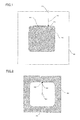
- FIG. 1 is a view illustrating an example of machining a punch shape by a wire electric discharge machine.
- Reference numeral 41 denotes a machining start point
- reference numeral 42 denotes an approach
- reference numeral 43 denotes a main machining start point
- reference numeral 44 denotes a cut-off portion
- reference numeral 45 denotes a shape of a machined product
- reference numeral 46 denotes a cut-off portion.
- FIG. 2 is a view illustrating an example of machining a die shape by the wire electric discharge machine.
- Reference numeral 51 denotes a machining start point
- reference numeral 52 denotes an approach
- reference numeral 53 denotes a main machining start point
- reference numeral 54 denotes a shape of a machined product
- reference numeral 55 denotes a cut-off portion.
- An inner side of a machining route is used as a machined product in the machining in FIG. 1 .
- the cut-off portions 44 and 46 are previously set, the machined product shape 45 is cut off, and then a boundary portion between the machined product shape 45 and the cut-off portion 44 is finished by grinding and the like, in general.
- an outer side of the machining route is used as a machined product.
- the machining of a section which is not necessary as the product is generally set before the machining of a shape which is necessary as the product (such machining is hereinafter refer to as main machining).
- a section between the machining start point 41 and the main machining start point 43 is the approach 42
- a section between the machining start point 51 and the main machining start point 53 is the approach 52.
- a compensation value is determined on the basis of information when the approaches 42 and 52 are machined.
- a point at which a machining is started is a point located behind the point at which the main machining is started or a point located in front of the point at which the main machining is started.
- the main machining is not started at the point (for example, the machining start point 41 as shown in FIG. 1 ) at which machining is started.
- a point at which a machining is started is a point located in front of the point at which the main machining is started.
- it is determined whether a point at which a machining is started is a point located behind the point at which the main machining is started or a point located in front of the point at which the main machining is started.
- a machining section for measuring (hereinafter refer to as measuring section) is decided in the approach 42.
- measuring section In general machining by wire electric discharge machines, there is a case that "special dedicated control", applied only to the approach 42, is performed just after starting a machining along the approach 42, or just before finishing a machining along the approach 42.
- special dedicated control In the case where the special dedicated control is valid, there is a case that an electric current contributing to the machining is a subject to be controlled.
- the measurement for deciding the current compensation value according to the present invention is performed in a section in which "special dedicated control" in the approaches is not valid.
- a point at which a machining is started is determined to be a point located behind the point at which the main machining is started, the average electric current and the electric discharge frequency at the time when the actual machining is performed are measured, after reaching a measuring section (a machining section for measuring in the approach 42). Thereafter, the measurement is finished at a point of time an aggregate calculation of data necessary for computing is completed, and the electric current contributing to the machining is computed.
- wire electric discharge machines have standard machining conditions. These standard machining conditions are obtained by a result of tests by a wire electric discharge machine manufacturer.
- the wire electric discharge machine manufacturer machines workpieces for testing, and adjusts machining conditions so as to obtain a desired result of machining.
- the electric current contributing to the machining that is carried out when the standard machining conditions were acquired is stored in a memory unit 73 of a numerical controller 71 in advance ( FIG. 4 ).
- the electric current contributing to the machining in the approach 42 mentioned above is compared with the electric current contributing to the machining that is carried out when the standard machining conditions were acquired, which are previously stored in the numerical controller 71. If the electric current contributing to the machining in the approach 42 is absolutely identical to the electric current contributing to the machining that is carried out when the standard machining conditions were acquired, it is not necessary to correct the electric current contributing to the machining, however, in the case where they are different from each other, the electric current contributing to the machining is adjusted by changing the electric voltage of the machining power source.
- the value for changing the electric voltage of the machining power source is stored as a compensation value in the memory unit 73 in the numerical controller 71, and is set as the compensation value of the machining voltage before starting the main machining.
- the main machining is performed by applying the compensation value to the standard conditions which are set at a time when the main machining is started (that is, by modifying the set standard conditions).
- the same compensation value is used during the main machining (that is, the current set machining conditions are not modified in process of the main machining).
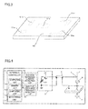
- the wire electric discharge machine as shown in FIG. 4 corresponds to a conventional wire electric discharge machine as shown in FIG. 10 to which an average machining current pulse detecting unit 75, an electric discharge frequency detecting unit 76, the numerical controller 71, a computing unit 72, the memory unit 73, a comparing unit 74, and a determining unit 77 are added.
- FIG. 5 is a flow chart showing a computing process of the compensation value of the machining voltage by the wire electric discharge machine shown in FIG. 4 . A description of a process in each of steps will be given below.
- Step SA1 When the machining is started, it is determined whether the point at which a machining is started is a point located behind the point at which the main machining is started or a point located in front of the point at which the main machining is started. If the point is determined to be a point located behind the point at which the main machining is started (No), the process proceeds to Step SA2. On the other hand, if the point is determined to be a point located in front of the point at which the main machining is started (Yes), the process proceeds to Step SA9, and the main machining is started without computing or inputting the compensation value. How to determine whether the main machining is started or not will be described later.
- Step SA2 It is determined that the point at which a machining is started lies in an approach, and sets a measuring section in a section in the approach located behind the point at which the main machining is started, other than sections in which "special dedicated control" is required.
- Step SA3 It is determined whether or not the machining reaches the measuring section set in the previous Step SA2, and if the machining does not reach the measuring section yet (No), the process in Step SA3 is repeated until the machining reaches the measuring section, and if the machining reaches the measuring section (Yes), on the other hand, the process proceeds to Step SA4.
- Step SA4 An electric current and an electric discharge frequency at the time when machining is under way are measured in the measuring section.
- Step SA5 It is determined whether the measurement is completed or not. If the measurement is not completed yet (No), the process proceeds to Step SA6, and if the measurement is completed (Yes), on the other hand, the process proceeds to Step SA7.
- Step SA6 The process waits ready for a predetermined time, and thereafter returns to Step SA5.
- Step SA7 The electric current contributing to the machining is computed on the basis of the result of measurement in the measuring section in the previous Step SA4.
- Step SA8 The compensation value contributing to the machining is computed on the basis of the result of measurement in the measuring section in the previous Step SA4. Examples of how to compute the electric current and the compensation value in Steps SA7 and SA8 will be mentioned later.
- Step SA9 The main machining is started.
- the machining When the machining is started, it is determined, by using a code in an NC program, whether or not a point at which the machining is started lies in an approach which is located behind the point at which the main machining is started.
- a code (M**) which shows starting of the main machining during a time interval between a start (G92X0Y0) of the machining program and a start (G41G01Y-1.) of the main machining is contained in the program, then it is possible to determine whether the current point lies in an approach located behind the point at which the main machining is started or in the machining route in which the main machining is under way, based on whether a current program block under execution lies before the code (M**) or after the code (M**).
- a case where a machining shown in FIG. 6 , for example, is carried out is considered, determining that a point at which a machining is started lies in a location before the point at which the main machining is started.
- a section (an approach) from a machining start point 41 to a main machining start point 43 is divided into a first dedicated-control valid section 81, a measuring section 82, and a second dedicated-control valid section 83.
- the remaining section excluding the first and second dedicated-control valid sections 81 and 83 from the approach is set to the measuring section 82.
- Distances (route lengths) of the dedicated-control valid sections 81 and 83 are determined by parameters in advance. If a position at which machining is under way is a distance equal to or more than the first dedicated-control valid section 81 ahead of the machining start point 41 and also is a distance equal to or more than the second dedicated-control valid section 83 short of the main machining start point 43, then it is determined that the position lies in a section in which the dedicated control in an approach is not valid.
- Measurement in the measuring section 82 is carried out under time control. Even measurement in the measuring section 82, it is not necessary to carry out the measurement over the entire area of the measuring section 82 as long as the collection of the necessary data is completed. It is determined every predetermined time whether the measurement is completed or not, before the measurement is completed, and the measurement is completed at a time when collection of necessary data is completed.
- An average machining current pulse and an electric discharge frequency are detected in an average machining current pulse detecting unit and an electric discharge frequency detecting unit, during a set measuring period t1, after the machining proceeds to an area of the measuring section 82.
- the average machining current pulse when the machining is actually performed during the measuring period t1 is set to Ia, and the electric discharge frequency is set to b.
- a time width of a pulse of a pulse current contributing the machining is set to ⁇ , and is controlled with an ON time of the switching element. A relationship among them is shown in FIG. 7 .
- I p I a ⁇ t 1 b ⁇ ⁇
- Data for compensating the voltage E of the machining power source 3 to E' is stored, and the compensation data is set in the machining power source 3 from the numerical controller 71 before the main machining is started.
- a second embodiment of the wire electric discharge machine is approximately the same as the first embodiment of the wire electric discharge machine mentioned above in its configuration and function, however, a computing method of compensating the electric voltage of the machining power source 3 is different from the first embodiment.
- the electric current Ip becomes equal to the peak current Ip (std) at the time of acquiring the standard machining conditions by compensating the electric voltage E to E2.
- Data for compensating the voltage of the machining power source 3 to E2 is stored, and is set to the machining power source 3 from the numerical controller 71 before the main machining is started.
- the compensation value of the power source voltage is decided on the basis of the ratio or the difference between the reference peak current value and the peak current value which is computed by the computing unit 72, however, the compensation value may be decided according to the other computing methods. Further, in these embodiments, the value of the pulse current is set to the fixed value for simplification, however, it is possible to compute without setting any fixed value.
Landscapes
- Engineering & Computer Science (AREA)
- Mechanical Engineering (AREA)
- Chemical & Material Sciences (AREA)
- Chemical Kinetics & Catalysis (AREA)
- Electrochemistry (AREA)
- Automation & Control Theory (AREA)
- Human Computer Interaction (AREA)
- Manufacturing & Machinery (AREA)
- Physics & Mathematics (AREA)
- General Physics & Mathematics (AREA)
- Electrical Discharge Machining, Electrochemical Machining, And Combined Machining (AREA)
Abstract
Description
- The present invention relates to a wire electric discharge machine having a function of compensating a machining current pulse of a wire electric discharge machine.
- The wire electric discharge machine machines a workpiece into a desired shape by applying an electric voltage between a wire electrode and the workpiece to generate electric discharge between them, while changing a relative position between the wire electrode and the workpiece. Generally, in the electric discharge machining of the workpiece, arequiredprecisionvaries according to a material of the workpiece or a thickness of the workpiece, however, a precision in several microns order may be often required as a higher precision.
- An example of a general wire electric discharge machine will be shown in
FIG. 10 . - A
machining power source 3 includes adirect voltage source 21 and aswitching element 22 which changes an electric voltage supplied from thedirect voltage source 21 to a high frequency pulse. The generated high frequency pulse is fed to an electric supply portion 5 via anelectric supply line 4, and is applied to a side of awire electrode 1 which is supported by a wire electrode support portion 8, and a side of a workpiece 2. - Since the pulse applied to the side of the
wire electrode 1 and the side of the workpiece 2 has a high frequency, theelectric supply line 4 equivalently includes an inductance component. Further, the inductance component varies dependent upon the attitude of anelectric supply line 4 and the like. Further, a distance from the electric supply portion 5 to an electric discharge point (that is, of an electric discharge route) is different according to the relative position between thewire electrode 1 and the workpiece 2, and a resistance component is differentiated by the difference. Thewayofflowingofelectric current is differentiated by the change of the impedances of these electric discharge routes. There is a problem that the difference of the way of flowing of electric current directly affects a machining speed and a machining precision. - With regard to the problem that the way of flowing of electric current varies according to the relative position between the wire electrode and the workpiece, or the state of a subj ect to be machined, a technique of detecting a peak current and output voltage so as to compare the detected values with reference values, and adjusting the output voltage according to the result of comparison is disclosed in Japanese Patent Application Laid-Open No.
59-205228 3820989 - Further, Japanese Patent Application Laid-Open No.
10-138048 - Further, Japanese Patent Application Laid-Open No.
10-138048 - Accordingly, an object of the present invention is to provide a wire electric discharge machine which can perform a machining by computing an electric current at the machining time on the basis of an average electric current and an electric discharge frequency before machining (mainly machining) a shape desired as a product, and compensating a power source voltage for machining, before starting a wire electric discharge machining.
- A wire electric discharge machine according to the present invention machines applies electric voltage between a wire electrode and a workpiece to generate electric discharge between them, while changing a relative position between the wire electrode and the workpiece, thereby machining the workpiece into a desired shape. The wire electric discharge machine comprising: a first detecting unit that detects an average electric current; a second detecting unit that detects an electric discharge frequency; a determining unit that determines, when starting a machining, whether or not the machining is a machining in an approach up to a shape required as a product; a computing unit configured to set a measuring section for measuring an average electric current and an electric discharge frequency at the time when machining is carried, in the approach, when the determining unit determines that the machining is carried out in the approach, and compute a peak current at the time when machining is under way, on the basis of the average electric current and the electric discharge frequency detected when machining is carried out in the set measuring section; a memory unit that stores a reference peak current; a comparing unit that compares the peak current at the time when machining is under way, obtained by the computation by the computing unit, with the reference peak current stored in the memory unit; and a compensation voltage calculating unit that calculates an electric voltage of a machining power source for compensating the peak current at a portion where machining of the machined shape is carried out, on the basis of a result of comparison by the comparing unit.
- According to the wire electric discharge machine, since the electric voltage of the machining power source is calculated by using a section of an approach in the workpiece up to the shape which is necessary for the product, as the measuring section, it is possible to perform compensation while taking into consideration the influence of the workpiece. Further, compensation of the power source voltage is performed according to the result of measurement in the section just before the main machining, it is possible to perform the compensation with a high degree of accuracy, without any delay. Further, by determining whether the machining route is an approach or not, before the measurement, the compensation value is neither computed nor input in the case where the main machining is already performed when the machining is started.
- The determining unit may determine whether a machining route is the approach or not on the basis of a code in an NC program of the wire electric discharge machine.
- When the determining unit determines that the machining under way is the machining in the approach, a section in which a control dedicated for the approach is not valid may be set to the measuring section.
- The computing unit may be configured to compute the peak current at the time when machining is under way, on the basis of an integral value of the average electric current, assuming that the peak current value at a time when the average electric current and the electric discharge frequency are measured is constant.
- The compensation voltage calculating unit may be configured to calculate an electric voltage of a machining power source on the basis of a ratio or difference between the peak current obtained by the computation by the computing unit and the reference peak current stored in the memory unit.
- According to the configuration mentioned above, the present invention can provide a wire electric discharge machine which is configured such that the machining can be performed by computing the electric current at the machining time on the basis of the average electric current and the electric discharge frequency in the machining before machining the shape desired as the product, and compensating the power source voltage for machining, before starting the wire electric discharge machining.
- The above objects and feature and the other objects and features of the present invention will be apparent from the following description of embodiments with reference to the accompanying drawings. Among these drawings:
-
FIG. 1 is a view illustrating an example of machining a punch shape by a wire electric discharge machine; -
FIG. 2 is a view illustrating an example of machining a die shape by the wire electric discharge machine; -
FIG. 3 shows an example of machining in the case where a plurality of shapes are machined in one workpiece, in the machining of the die shape by using the wire electric discharge machine; -
FIG. 4 is a view illustrating an outline of a first embodiment of a wire electric discharge machine having a peak current compensation function according to the present invention; -
FIG. 5 is a flow chart showing a computing process of a compensation value of machining voltage by the wire electric discharge machine shown inFIG. 4 ; -
FIG. 6 is a view illustrating a case where an approach is divided into three sections including a first dedicated-control valid section, a measuring section and a second dedicated-control valid section, in the machining example inFIG. 1 ; -
FIG. 7 is a view showing a relationship between a pulse current and an average machining current pulse in the measuring section inFIG. 6 ; -
FIG. 8 is a view showing an example of performing determination of an approach by inserting a code for starting a main machining, in an NC program; -
FIG. 9 is a view showing an example of performing determination of an approach on the basis of whether an offset is invalid or not, in the NC program; and -
FIG. 10 is a view showing a conventional general wire electric discharge machine. - Examples of machining by a first embodiment of a wire electric discharge machine is explained with reference to
FIGS. 1 and 2 . -
FIG. 1 is a view illustrating an example of machining a punch shape by a wire electric discharge machine.Reference numeral 41 denotes a machining start point,reference numeral 42 denotes an approach,reference numeral 43 denotes a main machining start point,reference numeral 44 denotes a cut-off portion,reference numeral 45 denotes a shape of a machined product, andreference numeral 46 denotes a cut-off portion. -
FIG. 2 is a view illustrating an example of machining a die shape by the wire electric discharge machine.Reference numeral 51 denotes a machining start point,reference numeral 52 denotes an approach,reference numeral 53 denotes a main machining start point,reference numeral 54 denotes a shape of a machined product, and reference numeral 55 denotes a cut-off portion. - An inner side of a machining route is used as a machined product in the machining in
FIG. 1 . In this machining of the punch shape, the cut-offportions machined product shape 45 is cut off, and then a boundary portion between themachined product shape 45 and the cut-offportion 44 is finished by grinding and the like, in general. On the other hand, in the machining as shown inFIG. 2 (in the machining of a die shape), an outer side of the machining route is used as a machined product. - In both of the machining of the punch shape in
FIG. 1 and the machining of the die shape inFIG. 2 , the machining of a section which is not necessary as the product (such a section is hereinafter referred to as approach) is generally set before the machining of a shape which is necessary as the product (such machining is hereinafter refer to as main machining). - In the example of the machining of the punch shape as shown in
FIG. 1 , a section between themachining start point 41 and the mainmachining start point 43 is theapproach 42, whereas, in the example of the machining of the die shape inFIG. 2 , a section between themachining start point 51 and the mainmachining start point 53 is theapproach 52. In both of the cases inFIGS. 1 and 2 , a compensation value is determined on the basis of information when theapproaches - First of all, it is determined whether a point at which a machining is started is a point located behind the point at which the main machining is started or a point located in front of the point at which the main machining is started. In the case where the machining is started for the first time after installing a workpiece, the main machining is not started at the point (for example, the
machining start point 41 as shown inFIG. 1 ) at which machining is started. On the other hand, for example, in the case where a wire disconnection is generated during the main machining, and the machining is started after recovery of the wire disconnection (that is, after the wire is connected), a point at which a machining is started (restarted) is a point located in front of the point at which the main machining is started. As mentioned above, it is determined whether a point at which a machining is started is a point located behind the point at which the main machining is started or a point located in front of the point at which the main machining is started. - In the case where it is determined that a point at which a machining is started is a point located behind the point at which the main machining is started, a machining section for measuring (hereinafter refer to as measuring section) is decided in the
approach 42. In general machining by wire electric discharge machines, there is a case that "special dedicated control", applied only to theapproach 42, is performed just after starting a machining along theapproach 42, or just before finishing a machining along theapproach 42. In the case where the special dedicated control is valid, there is a case that an electric current contributing to the machining is a subject to be controlled. The measurement for deciding the current compensation value according to the present invention is performed in a section in which "special dedicated control" in the approaches is not valid. - In the case where a point at which a machining is started is determined to be a point located in front of the point at which the main machining is started, the main machining is directly performed. In this case, since the compensation value is already decided before starting the main machining which is already performed, computation and input of the compensation value are not performed when the current main machining is performed.
- On the other hand, in the case where a point at which a machining is started is determined to be a point located behind the point at which the main machining is started, the average electric current and the electric discharge frequency at the time when the actual machining is performed are measured, after reaching a measuring section (a machining section for measuring in the approach 42). Thereafter, the measurement is finished at a point of time an aggregate calculation of data necessary for computing is completed, and the electric current contributing to the machining is computed.
- In general, wire electric discharge machines have standard machining conditions. These standard machining conditions are obtained by a result of tests by a wire electric discharge machine manufacturer. The wire electric discharge machine manufacturer machines workpieces for testing, and adjusts machining conditions so as to obtain a desired result of machining. The electric current contributing to the machining that is carried out when the standard machining conditions were acquired is stored in a
memory unit 73 of anumerical controller 71 in advance (FIG. 4 ). - The electric current contributing to the machining in the
approach 42 mentioned above is compared with the electric current contributing to the machining that is carried out when the standard machining conditions were acquired, which are previously stored in thenumerical controller 71. If the electric current contributing to the machining in theapproach 42 is absolutely identical to the electric current contributing to the machining that is carried out when the standard machining conditions were acquired, it is not necessary to correct the electric current contributing to the machining, however, in the case where they are different from each other, the electric current contributing to the machining is adjusted by changing the electric voltage of the machining power source. - The value for changing the electric voltage of the machining power source is stored as a compensation value in the
memory unit 73 in thenumerical controller 71, and is set as the compensation value of the machining voltage before starting the main machining. - As a result, prior to start of the main machining, a state in which the compensation value has been set is achieved, and the main machining is performed by applying the compensation value to the standard conditions which are set at a time when the main machining is started (that is, by modifying the set standard conditions). With regard to one shape, the same compensation value is used during the main machining (that is, the current set machining conditions are not modified in process of the main machining).
- Generally, in the case of machining punch shapes as shown in
FIG. 1 , the machining is completed every one shape. On the other hand, in the case of machining die shapes as shown inFIG. 2 , there is a case that a plurality of shapes are machined in one workpiece as shown inFIG. 3 . In this case, the similar compensation value is calculated every main machining applied to each of the machined shapes. - An outline of the first embodiment of the wire electric discharge machine having peak current compensation function according to the present invention is explained with reference to
FIG. 4 . - The wire electric discharge machine as shown in
FIG. 4 corresponds to a conventional wire electric discharge machine as shown inFIG. 10 to which an average machining currentpulse detecting unit 75, an electric dischargefrequency detecting unit 76, thenumerical controller 71, a computing unit 72, thememory unit 73, a comparing unit 74, and a determining unit 77 are added. -
FIG. 5 is a flow chart showing a computing process of the compensation value of the machining voltage by the wire electric discharge machine shown inFIG. 4 . A description of a process in each of steps will be given below. - (Step SA1) When the machining is started, it is determined whether the point at which a machining is started is a point located behind the point at which the main machining is started or a point located in front of the point at which the main machining is started. If the point is determined to be a point located behind the point at which the main machining is started (No), the process proceeds to Step SA2. On the other hand, if the point is determined to be a point located in front of the point at which the main machining is started (Yes), the process proceeds to Step SA9, and the main machining is started without computing or inputting the compensation value. How to determine whether the main machining is started or not will be described later.
- (Step SA2) It is determined that the point at which a machining is started lies in an approach, and sets a measuring section in a section in the approach located behind the point at which the main machining is started, other than sections in which "special dedicated control" is required.
- (Step SA3) It is determined whether or not the machining reaches the measuring section set in the previous Step SA2, and if the machining does not reach the measuring section yet (No), the process in Step SA3 is repeated until the machining reaches the measuring section, and if the machining reaches the measuring section (Yes), on the other hand, the process proceeds to Step SA4.
- (Step SA4) An electric current and an electric discharge frequency at the time when machining is under way are measured in the measuring section.
- (Step SA5) It is determined whether the measurement is completed or not. If the measurement is not completed yet (No), the process proceeds to Step SA6, and if the measurement is completed (Yes), on the other hand, the process proceeds to Step SA7.
- (Step SA6) The process waits ready for a predetermined time, and thereafter returns to Step SA5.
- (Step SA7) The electric current contributing to the machining is computed on the basis of the result of measurement in the measuring section in the previous Step SA4.
- (Step SA8) The compensation value contributing to the machining is computed on the basis of the result of measurement in the measuring section in the previous Step SA4. Examples of how to compute the electric current and the compensation value in Steps SA7 and SA8 will be mentioned later.
- (Step SA9) The main machining is started.
- When the machining is started, it is determined, by using a code in an NC program, whether or not a point at which the machining is started lies in an approach which is located behind the point at which the main machining is started.
- For example, as in the case of a program shown in
FIG. 8 , if a code (M**) which shows starting of the main machining during a time interval between a start (G92X0Y0) of the machining program and a start (G41G01Y-1.) of the main machining is contained in the program, then it is possible to determine whether the current point lies in an approach located behind the point at which the main machining is started or in the machining route in which the main machining is under way, based on whether a current program block under execution lies before the code (M**) or after the code (M**). - As an alternative method, if there is an offset invalidating block (G91G01Y10) or an offset validating block (G41G01Y-1.) after start (G92X0Y0) of the machining program, as in the case of the program shown in
FIG. 9 , it is possible to determine whether or not a point at which a machining is started lies in an approach located behind the point at which the main machining is started, taking into consideration the fact that an offset during machining is generally made invalid in machining in an approach. - If the main machining has already been started and machining is started for the purpose of restarting the machining, computation and input of the compensation value has already been carried out in an approach located behind the point at which the main machining is started. Therefore, the machining is performed directly (that is, without any computation and input of the compensation value).
- Here, a case where a machining shown in
FIG. 6 , for example, is carried out is considered, determining that a point at which a machining is started lies in a location before the point at which the main machining is started. - A section (an approach) from a
machining start point 41 to a mainmachining start point 43 is divided into a first dedicated-controlvalid section 81, a measuringsection 82, and a second dedicated-controlvalid section 83. The remaining section excluding the first and second dedicated-controlvalid sections section 82. - In wire electric discharge machines, there is a case that "dedicated control" in which a machining speed is lowered for the purpose of preventing disconnection of a wire electrode is made valid in the first and second dedicated-control
valid sections FIG. 6 (showing an example of machining a punch shape). The measuringsection 82 is determined to be a section in which the dedicated control in an approach is not valid. Even in the case of machining of die shapes as shown inFIG. 2 , there is a case that a section (a dedicated-control valid section) for making "dedicated control" valid is provided in theapproach 52, for preventing machined products from being damaged. - Distances (route lengths) of the dedicated-control
valid sections valid section 81 ahead of themachining start point 41 and also is a distance equal to or more than the second dedicated-controlvalid section 83 short of the mainmachining start point 43, then it is determined that the position lies in a section in which the dedicated control in an approach is not valid. - Measurement in the measuring
section 82 is carried out under time control. Even measurement in the measuringsection 82, it is not necessary to carry out the measurement over the entire area of the measuringsection 82 as long as the collection of the necessary data is completed. It is determined every predetermined time whether the measurement is completed or not, before the measurement is completed, and the measurement is completed at a time when collection of necessary data is completed. - An average machining current pulse and an electric discharge frequency are detected in an average machining current pulse detecting unit and an electric discharge frequency detecting unit, during a set measuring period t1, after the machining proceeds to an area of the measuring
section 82. The average machining current pulse when the machining is actually performed during the measuring period t1 is set to Ia, and the electric discharge frequency is set to b. A time width of a pulse of a pulse current contributing the machining is set to τ, and is controlled with an ON time of the switching element. A relationship among them is shown inFIG. 7 . - Here, as one example, computation is performed by a computing unit as follows:

wherein generally, a value of the pulse current contributing the machining is not constant, however, it is assumed, for simplification, that the value of the pulse current is set to a fixed value Ip, and the fixed value Ia is adopted even in the average machining current pulse. Then, the above expression (1) can be developed as the following expression (2).
- The value Ip determined as mentioned above is compared with a peak current Ip(std) that is set when deciding machine standard conditions stored in the
memory unit 73, and a ratio k thereof is determined according to the following expression (3).
- On the other hand, on the assumption that an impedance of a whole of the electric discharge route is Z1, it can be considered that the following relationship is established between Ip and Z1.

- Here, by compensating an electric voltage E of the
machining power source 3 to E' as follows, Ip becomes equal to the peak current Ip(std) at the time of acquiring the standard machining conditions.
- Data for compensating the voltage E of the
machining power source 3 to E' is stored, and the compensation data is set in themachining power source 3 from thenumerical controller 71 before the main machining is started. - A second embodiment of the wire electric discharge machine is approximately the same as the first embodiment of the wire electric discharge machine mentioned above in its configuration and function, however, a computing method of compensating the electric voltage of the
machining power source 3 is different from the first embodiment. - A difference ΔI between Ip which is determined according to the above expression (2) and the electric current Ip(std) at the time of deciding the machine standard conditions stored in the
memory unit 73 is obtained.
- Further, on the assumption that an impedance of a whole of the electric discharge route is Z2, it can be considered that the following relationship is established between Ip and Z2.

- Here, for the purpose of adjusting Ip to Ip(std) by compensating the electric voltage E to E2, it can be considered that the following expression is established.

- As mentioned above, the electric current Ip becomes equal to the peak current Ip (std) at the time of acquiring the standard machining conditions by compensating the electric voltage E to E2. Data for compensating the voltage of the
machining power source 3 to E2 is stored, and is set to themachining power source 3 from thenumerical controller 71 before the main machining is started. - In these embodiments, as the method of compensating the electric voltage of the
machining power source 3, the compensation value of the power source voltage is decided on the basis of the ratio or the difference between the reference peak current value and the peak current value which is computed by the computing unit 72, however, the compensation value may be decided according to the other computing methods. Further, in these embodiments, the value of the pulse current is set to the fixed value for simplification, however, it is possible to compute without setting any fixed value.
Claims (6)
- A wire electric discharge machine applying electric voltage between a wire electrode and a workpiece to generate electric discharge between them, while changing a relative position between the wire electrode and the workpiece, thereby machining the workpiece into a desired shape, the wire electric discharge machine comprising:a first detecting unit that detects an average electric current;a second detecting unit that detects an electric discharge frequency;a determining unit that determines, when starting a machining, whether or not the machining is a machining in an approach up to a shape required as a product;a computing unit configured to set a measuring section for measuring an average electric current and an electric discharge frequency at the time when machining is carried, in the approach, when the determining unit determines that the machining is carried out in the approach, and compute a peak current at the time when machining is under way, on the basis of the average electric current and the electric discharge frequency detected when machining is carried out in the set measuring section;a memory unit that stores a reference peak current;a comparing unit that compares the peak current at the time when machining is under way, obtained by the computation by the computing unit, with the reference peak current stored in the memory unit; anda compensation voltage calculating unit that calculates an electric voltage of a machining power source for compensating the peak current at a portion where machining of the machined shape is carried out, on the basis of a result of comparison by the comparing unit.
- The wire electric discharge machine according to claim 1, wherein the determining unit determines whether a machining route is the approach or not on the basis of a code in an NC program of the wire electric discharge machine.
- The wire electric discharge machine according to claim 1, wherein, when the determining unit determines that the machining under way is the machining in the approach, a section in which a control dedicated for the approach is not valid is set to the measuring section.
- The wire electric discharge machine according to claim 1, wherein the computing unit is configured to compute the peak current at the time when machining is under way, on the basis of an integral value of the average electric current, assuming that the peak current value at a time when the average electric current and the electric discharge frequency are measured is constant.
- The wire electric discharge machine according to claim 1, wherein the compensation voltage calculating unit is configured to calculate an electric voltage of a machining power source on the basis of a ratio between the peak current obtained by the computation by the computing unit and the reference peak current stored in the memory unit.
- The wire electric discharge machine according to claim 1, wherein the compensation voltage calculating unit is configured to calculate an electric voltage of a machining power source on the basis of a difference between the peak current obtained by the computation by the computing unit and the reference peak current stored in the memory unit.
Applications Claiming Priority (1)
| Application Number | Priority Date | Filing Date | Title |
|---|---|---|---|
| JP2012249541A JP5587963B2 (en) | 2012-11-13 | 2012-11-13 | Wire electrical discharge machine with peak current correction function |
Publications (3)
| Publication Number | Publication Date |
|---|---|
| EP2730361A2 true EP2730361A2 (en) | 2014-05-14 |
| EP2730361A3 EP2730361A3 (en) | 2018-01-03 |
| EP2730361B1 EP2730361B1 (en) | 2021-11-24 |
Family
ID=49622670
Family Applications (1)
| Application Number | Title | Priority Date | Filing Date |
|---|---|---|---|
| EP13192227.0A Active EP2730361B1 (en) | 2012-11-13 | 2013-11-08 | Wire electric discharge machine having peak current compensation function |
Country Status (4)
| Country | Link |
|---|---|
| US (1) | US9459611B2 (en) |
| EP (1) | EP2730361B1 (en) |
| JP (1) | JP5587963B2 (en) |
| CN (1) | CN103801773B (en) |
Families Citing this family (3)
| Publication number | Priority date | Publication date | Assignee | Title |
|---|---|---|---|---|
| CN106112153B (en) * | 2016-07-26 | 2018-03-23 | 苏州科技大学 | Nc wire-cutting molybdenum filament vertical survey bearing calibration and device |
| EP4194130A1 (en) * | 2021-12-10 | 2023-06-14 | Thermocompact | Method and device for optimised machining by wire electrical discharge machining |
| CN114211208B (en) * | 2021-12-27 | 2024-02-27 | 安徽金寨将军磁业有限公司 | Method for processing arc surface of permanent ferrite magnetic shoe alloy die |
Family Cites Families (15)
| Publication number | Priority date | Publication date | Assignee | Title |
|---|---|---|---|---|
| JPS5163094A (en) * | 1974-11-30 | 1976-06-01 | Inoue Japax Res | WAIYAKATSUTOHODEN KAKOSOCHI |
| JPS59205228A (en) | 1983-05-04 | 1984-11-20 | Mitsubishi Electric Corp | Power supply for electric discharge machining |
| JP2567262B2 (en) * | 1987-11-16 | 1996-12-25 | ファナック株式会社 | Method and device for detecting machining conditions of wire electric discharge machine |
| JPH04189421A (en) * | 1990-11-20 | 1992-07-07 | Mitsubishi Electric Corp | Wire electric discharge machining method and its device |
| JP2722867B2 (en) | 1991-07-01 | 1998-03-09 | 三菱電機株式会社 | Wire electric discharge machine |
| JPH05163094A (en) | 1991-12-17 | 1993-06-29 | Hitachi Cable Ltd | Production of compound semiconductor crystal |
| JP3341494B2 (en) * | 1994-10-25 | 2002-11-05 | 三菱電機株式会社 | Power control device for wire electric discharge machine |
| JP3375500B2 (en) | 1996-10-31 | 2003-02-10 | 三菱電機株式会社 | Electric discharge machining method and electric discharge machine |
| JP3780649B2 (en) | 1997-08-05 | 2006-05-31 | 三菱電機株式会社 | Electric discharge machine and electric discharge machining method |
| CN1238146C (en) | 2000-05-26 | 2006-01-25 | 三菱电机株式会社 | Apparatus for electrodischarge machining |
| JP2005066738A (en) * | 2003-08-22 | 2005-03-17 | Fanuc Ltd | Machining control method for wire-cut electric discharge machine |
| JP4588702B2 (en) * | 2004-03-01 | 2010-12-01 | 三菱電機株式会社 | EDM machine |
| JP4298764B2 (en) * | 2007-04-10 | 2009-07-22 | ファナック株式会社 | Control device for wire cut electric discharge machine |
| JP5137263B2 (en) * | 2009-10-19 | 2013-02-06 | 株式会社ソディック | Wire cut electric discharge machining apparatus and wire cut electric discharge machining method |
| JP4734447B2 (en) * | 2009-11-26 | 2011-07-27 | ファナック株式会社 | Wire cut electric discharge machine and electric discharge machining method |
-
2012
- 2012-11-13 JP JP2012249541A patent/JP5587963B2/en not_active Expired - Fee Related
-
2013
- 2013-11-08 EP EP13192227.0A patent/EP2730361B1/en active Active
- 2013-11-12 CN CN201310559634.6A patent/CN103801773B/en active Active
- 2013-11-13 US US14/079,122 patent/US9459611B2/en active Active
Non-Patent Citations (1)
| Title |
|---|
| None * |
Also Published As
| Publication number | Publication date |
|---|---|
| CN103801773B (en) | 2016-01-27 |
| JP5587963B2 (en) | 2014-09-10 |
| CN103801773A (en) | 2014-05-21 |
| US20140135974A1 (en) | 2014-05-15 |
| EP2730361A3 (en) | 2018-01-03 |
| US9459611B2 (en) | 2016-10-04 |
| EP2730361B1 (en) | 2021-11-24 |
| JP2014097538A (en) | 2014-05-29 |
Similar Documents
| Publication | Publication Date | Title |
|---|---|---|
| US8829383B2 (en) | Wire electric discharge machine and wire electric discharge machining method | |
| CN102371409B (en) | Wire-cut electric discharge machine having workpiece measuring mechanism | |
| EP3482860B1 (en) | Controller for wire electrical discharge machine and control method for a wire electrical discharge machine | |
| EP2272613B1 (en) | Wire-cut electric discharge machine with function to suppress local production of streaks during finish machining | |
| EP2730361B1 (en) | Wire electric discharge machine having peak current compensation function | |
| EP2767360B1 (en) | Wire electric discharge machine and calculation method for wire support positions of wire electric discharge machine | |
| CN102078990A (en) | Wire-cut electric discharge machine and electric discharge machining method | |
| CN104039491B (en) | Wire EDM | |
| US20160236292A1 (en) | Wire electrical discharge machining apparatus | |
| CN115673446B (en) | Wire cut electric discharge machining method and device capable of automatically measuring and compensating on line | |
| RU2553785C2 (en) | Method and device for tool correction | |
| EP3591834B1 (en) | Motor control device | |
| KR20080014708A (en) | Electrical Discharge Machining Apparatus And Method | |
| CN113874798A (en) | CNC device | |
| US4970362A (en) | Wire-cutting electric discharge machining device | |
| EP3072620B1 (en) | Wire electric discharge machine including unit for adjusting position of workpiece before calibrating | |
| KR101091171B1 (en) | A control method for a corp shear in continuous hot rolling equipment | |
| EP3305451B1 (en) | Machining time-estimating method for wire electrical discharge machine and control device for wire electrical discharge machine | |
| EP3715025A1 (en) | Machining tool and workpiece measurement method | |
| CN105848813A (en) | Apparatus and method for managing access to a resource | |
| EP3706952B1 (en) | Method for machining a glass pane | |
| JP4678711B2 (en) | Die-sinker EDM | |
| JPH0839399A (en) | Thermal displacement correcting device for machine tool | |
| Schulze et al. | The optimization of the spark erosive removal process–Dependencies and benefits | |
| JP2002254246A (en) | High-precision hole machining method by die-sinking micro-electric discharge machining |
Legal Events
| Date | Code | Title | Description |
|---|---|---|---|
| PUAI | Public reference made under article 153(3) epc to a published international application that has entered the european phase |
Free format text: ORIGINAL CODE: 0009012 |
|
| 17P | Request for examination filed |
Effective date: 20131108 |
|
| AK | Designated contracting states |
Kind code of ref document: A2 Designated state(s): AL AT BE BG CH CY CZ DE DK EE ES FI FR GB GR HR HU IE IS IT LI LT LU LV MC MK MT NL NO PL PT RO RS SE SI SK SM TR |
|
| AX | Request for extension of the european patent |
Extension state: BA ME |
|
| PUAL | Search report despatched |
Free format text: ORIGINAL CODE: 0009013 |
|
| AK | Designated contracting states |
Kind code of ref document: A3 Designated state(s): AL AT BE BG CH CY CZ DE DK EE ES FI FR GB GR HR HU IE IS IT LI LT LU LV MC MK MT NL NO PL PT RO RS SE SI SK SM TR |
|
| AX | Request for extension of the european patent |
Extension state: BA ME |
|
| RIC1 | Information provided on ipc code assigned before grant |
Ipc: B23H 7/02 20060101ALI20171130BHEP Ipc: B23H 7/14 20060101ALI20171130BHEP Ipc: B23H 1/02 20060101AFI20171130BHEP |
|
| STAA | Information on the status of an ep patent application or granted ep patent |
Free format text: STATUS: REQUEST FOR EXAMINATION WAS MADE |
|
| R17P | Request for examination filed (corrected) |
Effective date: 20180703 |
|
| RBV | Designated contracting states (corrected) |
Designated state(s): AL AT BE BG CH CY CZ DE DK EE ES FI FR GB GR HR HU IE IS IT LI LT LU LV MC MK MT NL NO PL PT RO RS SE SI SK SM TR |
|
| STAA | Information on the status of an ep patent application or granted ep patent |
Free format text: STATUS: EXAMINATION IS IN PROGRESS |
|
| 17Q | First examination report despatched |
Effective date: 20200715 |
|
| GRAP | Despatch of communication of intention to grant a patent |
Free format text: ORIGINAL CODE: EPIDOSNIGR1 |
|
| STAA | Information on the status of an ep patent application or granted ep patent |
Free format text: STATUS: GRANT OF PATENT IS INTENDED |
|
| INTG | Intention to grant announced |
Effective date: 20210630 |
|
| GRAS | Grant fee paid |
Free format text: ORIGINAL CODE: EPIDOSNIGR3 |
|
| GRAA | (expected) grant |
Free format text: ORIGINAL CODE: 0009210 |
|
| STAA | Information on the status of an ep patent application or granted ep patent |
Free format text: STATUS: THE PATENT HAS BEEN GRANTED |
|
| AK | Designated contracting states |
Kind code of ref document: B1 Designated state(s): AL AT BE BG CH CY CZ DE DK EE ES FI FR GB GR HR HU IE IS IT LI LT LU LV MC MK MT NL NO PL PT RO RS SE SI SK SM TR |
|
| REG | Reference to a national code |
Ref country code: GB Ref legal event code: FG4D |
|
| REG | Reference to a national code |
Ref country code: AT Ref legal event code: REF Ref document number: 1449474 Country of ref document: AT Kind code of ref document: T Effective date: 20211215 |
|
| REG | Reference to a national code |
Ref country code: DE Ref legal event code: R096 Ref document number: 602013080163 Country of ref document: DE |
|
| REG | Reference to a national code |
Ref country code: IE Ref legal event code: FG4D |
|
| REG | Reference to a national code |
Ref country code: LT Ref legal event code: MG9D |
|
| REG | Reference to a national code |
Ref country code: NL Ref legal event code: MP Effective date: 20211124 |
|
| REG | Reference to a national code |
Ref country code: AT Ref legal event code: MK05 Ref document number: 1449474 Country of ref document: AT Kind code of ref document: T Effective date: 20211124 |
|
| PG25 | Lapsed in a contracting state [announced via postgrant information from national office to epo] |
Ref country code: RS Free format text: LAPSE BECAUSE OF FAILURE TO SUBMIT A TRANSLATION OF THE DESCRIPTION OR TO PAY THE FEE WITHIN THE PRESCRIBED TIME-LIMIT Effective date: 20211124 Ref country code: LT Free format text: LAPSE BECAUSE OF FAILURE TO SUBMIT A TRANSLATION OF THE DESCRIPTION OR TO PAY THE FEE WITHIN THE PRESCRIBED TIME-LIMIT Effective date: 20211124 Ref country code: FI Free format text: LAPSE BECAUSE OF FAILURE TO SUBMIT A TRANSLATION OF THE DESCRIPTION OR TO PAY THE FEE WITHIN THE PRESCRIBED TIME-LIMIT Effective date: 20211124 Ref country code: BG Free format text: LAPSE BECAUSE OF FAILURE TO SUBMIT A TRANSLATION OF THE DESCRIPTION OR TO PAY THE FEE WITHIN THE PRESCRIBED TIME-LIMIT Effective date: 20220224 Ref country code: AT Free format text: LAPSE BECAUSE OF FAILURE TO SUBMIT A TRANSLATION OF THE DESCRIPTION OR TO PAY THE FEE WITHIN THE PRESCRIBED TIME-LIMIT Effective date: 20211124 |
|
| PG25 | Lapsed in a contracting state [announced via postgrant information from national office to epo] |
Ref country code: IS Free format text: LAPSE BECAUSE OF FAILURE TO SUBMIT A TRANSLATION OF THE DESCRIPTION OR TO PAY THE FEE WITHIN THE PRESCRIBED TIME-LIMIT Effective date: 20220324 Ref country code: SE Free format text: LAPSE BECAUSE OF FAILURE TO SUBMIT A TRANSLATION OF THE DESCRIPTION OR TO PAY THE FEE WITHIN THE PRESCRIBED TIME-LIMIT Effective date: 20211124 Ref country code: PT Free format text: LAPSE BECAUSE OF FAILURE TO SUBMIT A TRANSLATION OF THE DESCRIPTION OR TO PAY THE FEE WITHIN THE PRESCRIBED TIME-LIMIT Effective date: 20220324 Ref country code: PL Free format text: LAPSE BECAUSE OF FAILURE TO SUBMIT A TRANSLATION OF THE DESCRIPTION OR TO PAY THE FEE WITHIN THE PRESCRIBED TIME-LIMIT Effective date: 20211124 Ref country code: NO Free format text: LAPSE BECAUSE OF FAILURE TO SUBMIT A TRANSLATION OF THE DESCRIPTION OR TO PAY THE FEE WITHIN THE PRESCRIBED TIME-LIMIT Effective date: 20220224 Ref country code: NL Free format text: LAPSE BECAUSE OF FAILURE TO SUBMIT A TRANSLATION OF THE DESCRIPTION OR TO PAY THE FEE WITHIN THE PRESCRIBED TIME-LIMIT Effective date: 20211124 Ref country code: LV Free format text: LAPSE BECAUSE OF FAILURE TO SUBMIT A TRANSLATION OF THE DESCRIPTION OR TO PAY THE FEE WITHIN THE PRESCRIBED TIME-LIMIT Effective date: 20211124 Ref country code: HR Free format text: LAPSE BECAUSE OF FAILURE TO SUBMIT A TRANSLATION OF THE DESCRIPTION OR TO PAY THE FEE WITHIN THE PRESCRIBED TIME-LIMIT Effective date: 20211124 Ref country code: GR Free format text: LAPSE BECAUSE OF FAILURE TO SUBMIT A TRANSLATION OF THE DESCRIPTION OR TO PAY THE FEE WITHIN THE PRESCRIBED TIME-LIMIT Effective date: 20220225 Ref country code: ES Free format text: LAPSE BECAUSE OF FAILURE TO SUBMIT A TRANSLATION OF THE DESCRIPTION OR TO PAY THE FEE WITHIN THE PRESCRIBED TIME-LIMIT Effective date: 20211124 |
|
| PG25 | Lapsed in a contracting state [announced via postgrant information from national office to epo] |
Ref country code: SM Free format text: LAPSE BECAUSE OF FAILURE TO SUBMIT A TRANSLATION OF THE DESCRIPTION OR TO PAY THE FEE WITHIN THE PRESCRIBED TIME-LIMIT Effective date: 20211124 Ref country code: SK Free format text: LAPSE BECAUSE OF FAILURE TO SUBMIT A TRANSLATION OF THE DESCRIPTION OR TO PAY THE FEE WITHIN THE PRESCRIBED TIME-LIMIT Effective date: 20211124 Ref country code: RO Free format text: LAPSE BECAUSE OF FAILURE TO SUBMIT A TRANSLATION OF THE DESCRIPTION OR TO PAY THE FEE WITHIN THE PRESCRIBED TIME-LIMIT Effective date: 20211124 Ref country code: EE Free format text: LAPSE BECAUSE OF FAILURE TO SUBMIT A TRANSLATION OF THE DESCRIPTION OR TO PAY THE FEE WITHIN THE PRESCRIBED TIME-LIMIT Effective date: 20211124 Ref country code: DK Free format text: LAPSE BECAUSE OF FAILURE TO SUBMIT A TRANSLATION OF THE DESCRIPTION OR TO PAY THE FEE WITHIN THE PRESCRIBED TIME-LIMIT Effective date: 20211124 Ref country code: CZ Free format text: LAPSE BECAUSE OF FAILURE TO SUBMIT A TRANSLATION OF THE DESCRIPTION OR TO PAY THE FEE WITHIN THE PRESCRIBED TIME-LIMIT Effective date: 20211124 |
|
| REG | Reference to a national code |
Ref country code: DE Ref legal event code: R097 Ref document number: 602013080163 Country of ref document: DE |
|
| PLBE | No opposition filed within time limit |
Free format text: ORIGINAL CODE: 0009261 |
|
| STAA | Information on the status of an ep patent application or granted ep patent |
Free format text: STATUS: NO OPPOSITION FILED WITHIN TIME LIMIT |
|
| PG25 | Lapsed in a contracting state [announced via postgrant information from national office to epo] |
Ref country code: AL Free format text: LAPSE BECAUSE OF FAILURE TO SUBMIT A TRANSLATION OF THE DESCRIPTION OR TO PAY THE FEE WITHIN THE PRESCRIBED TIME-LIMIT Effective date: 20211124 |
|
| 26N | No opposition filed |
Effective date: 20220825 |
|
| PG25 | Lapsed in a contracting state [announced via postgrant information from national office to epo] |
Ref country code: SI Free format text: LAPSE BECAUSE OF FAILURE TO SUBMIT A TRANSLATION OF THE DESCRIPTION OR TO PAY THE FEE WITHIN THE PRESCRIBED TIME-LIMIT Effective date: 20211124 |
|
| PG25 | Lapsed in a contracting state [announced via postgrant information from national office to epo] |
Ref country code: IT Free format text: LAPSE BECAUSE OF FAILURE TO SUBMIT A TRANSLATION OF THE DESCRIPTION OR TO PAY THE FEE WITHIN THE PRESCRIBED TIME-LIMIT Effective date: 20211124 |
|
| PG25 | Lapsed in a contracting state [announced via postgrant information from national office to epo] |
Ref country code: MC Free format text: LAPSE BECAUSE OF FAILURE TO SUBMIT A TRANSLATION OF THE DESCRIPTION OR TO PAY THE FEE WITHIN THE PRESCRIBED TIME-LIMIT Effective date: 20211124 |
|
| GBPC | Gb: european patent ceased through non-payment of renewal fee |
Effective date: 20221108 |
|
| REG | Reference to a national code |
Ref country code: BE Ref legal event code: MM Effective date: 20221130 |
|
| PG25 | Lapsed in a contracting state [announced via postgrant information from national office to epo] |
Ref country code: LU Free format text: LAPSE BECAUSE OF NON-PAYMENT OF DUE FEES Effective date: 20221108 |
|
| PG25 | Lapsed in a contracting state [announced via postgrant information from national office to epo] |
Ref country code: IE Free format text: LAPSE BECAUSE OF NON-PAYMENT OF DUE FEES Effective date: 20221108 Ref country code: GB Free format text: LAPSE BECAUSE OF NON-PAYMENT OF DUE FEES Effective date: 20221108 |
|
| PG25 | Lapsed in a contracting state [announced via postgrant information from national office to epo] |
Ref country code: FR Free format text: LAPSE BECAUSE OF NON-PAYMENT OF DUE FEES Effective date: 20221130 Ref country code: BE Free format text: LAPSE BECAUSE OF NON-PAYMENT OF DUE FEES Effective date: 20221130 |
|
| PG25 | Lapsed in a contracting state [announced via postgrant information from national office to epo] |
Ref country code: HU Free format text: LAPSE BECAUSE OF FAILURE TO SUBMIT A TRANSLATION OF THE DESCRIPTION OR TO PAY THE FEE WITHIN THE PRESCRIBED TIME-LIMIT; INVALID AB INITIO Effective date: 20131108 |
|
| PG25 | Lapsed in a contracting state [announced via postgrant information from national office to epo] |
Ref country code: CY Free format text: LAPSE BECAUSE OF FAILURE TO SUBMIT A TRANSLATION OF THE DESCRIPTION OR TO PAY THE FEE WITHIN THE PRESCRIBED TIME-LIMIT Effective date: 20211124 |
|
| PG25 | Lapsed in a contracting state [announced via postgrant information from national office to epo] |
Ref country code: MK Free format text: LAPSE BECAUSE OF FAILURE TO SUBMIT A TRANSLATION OF THE DESCRIPTION OR TO PAY THE FEE WITHIN THE PRESCRIBED TIME-LIMIT Effective date: 20211124 |
|
| PG25 | Lapsed in a contracting state [announced via postgrant information from national office to epo] |
Ref country code: MT Free format text: LAPSE BECAUSE OF FAILURE TO SUBMIT A TRANSLATION OF THE DESCRIPTION OR TO PAY THE FEE WITHIN THE PRESCRIBED TIME-LIMIT Effective date: 20211124 |
|
| PGFP | Annual fee paid to national office [announced via postgrant information from national office to epo] |
Ref country code: DE Payment date: 20241022 Year of fee payment: 12 |
|
| PGFP | Annual fee paid to national office [announced via postgrant information from national office to epo] |
Ref country code: CH Payment date: 20241201 Year of fee payment: 12 |
|
| PG25 | Lapsed in a contracting state [announced via postgrant information from national office to epo] |
Ref country code: TR Free format text: LAPSE BECAUSE OF FAILURE TO SUBMIT A TRANSLATION OF THE DESCRIPTION OR TO PAY THE FEE WITHIN THE PRESCRIBED TIME-LIMIT Effective date: 20211124 |