EP2729422B1 - Vacuum glass sealing method and device - Google Patents
Vacuum glass sealing method and device Download PDFInfo
- Publication number
- EP2729422B1 EP2729422B1 EP11869133.6A EP11869133A EP2729422B1 EP 2729422 B1 EP2729422 B1 EP 2729422B1 EP 11869133 A EP11869133 A EP 11869133A EP 2729422 B1 EP2729422 B1 EP 2729422B1
- Authority
- EP
- European Patent Office
- Prior art keywords
- glass plates
- sealed
- partition plate
- plate
- air
- Prior art date
- Legal status (The legal status is an assumption and is not a legal conclusion. Google has not performed a legal analysis and makes no representation as to the accuracy of the status listed.)
- Active
Links
Images


Classifications
-
- C—CHEMISTRY; METALLURGY
- C03—GLASS; MINERAL OR SLAG WOOL
- C03B—MANUFACTURE, SHAPING, OR SUPPLEMENTARY PROCESSES
- C03B23/00—Re-forming shaped glass
- C03B23/20—Uniting glass pieces by fusing without substantial reshaping
- C03B23/24—Making hollow glass sheets or bricks
- C03B23/245—Hollow glass sheets
-
- C—CHEMISTRY; METALLURGY
- C03—GLASS; MINERAL OR SLAG WOOL
- C03C—CHEMICAL COMPOSITION OF GLASSES, GLAZES OR VITREOUS ENAMELS; SURFACE TREATMENT OF GLASS; SURFACE TREATMENT OF FIBRES OR FILAMENTS MADE FROM GLASS, MINERALS OR SLAGS; JOINING GLASS TO GLASS OR OTHER MATERIALS
- C03C27/00—Joining pieces of glass to pieces of other inorganic material; Joining glass to glass other than by fusing
- C03C27/06—Joining glass to glass by processes other than fusing
- C03C27/08—Joining glass to glass by processes other than fusing with the aid of intervening metal
-
- E—FIXED CONSTRUCTIONS
- E06—DOORS, WINDOWS, SHUTTERS, OR ROLLER BLINDS IN GENERAL; LADDERS
- E06B—FIXED OR MOVABLE CLOSURES FOR OPENINGS IN BUILDINGS, VEHICLES, FENCES OR LIKE ENCLOSURES IN GENERAL, e.g. DOORS, WINDOWS, BLINDS, GATES
- E06B3/00—Window sashes, door leaves, or like elements for closing wall or like openings; Layout of fixed or moving closures, e.g. windows in wall or like openings; Features of rigidly-mounted outer frames relating to the mounting of wing frames
- E06B3/66—Units comprising two or more parallel glass or like panes permanently secured together
- E06B3/6612—Evacuated glazing units
-
- E—FIXED CONSTRUCTIONS
- E06—DOORS, WINDOWS, SHUTTERS, OR ROLLER BLINDS IN GENERAL; LADDERS
- E06B—FIXED OR MOVABLE CLOSURES FOR OPENINGS IN BUILDINGS, VEHICLES, FENCES OR LIKE ENCLOSURES IN GENERAL, e.g. DOORS, WINDOWS, BLINDS, GATES
- E06B3/00—Window sashes, door leaves, or like elements for closing wall or like openings; Layout of fixed or moving closures, e.g. windows in wall or like openings; Features of rigidly-mounted outer frames relating to the mounting of wing frames
- E06B3/66—Units comprising two or more parallel glass or like panes permanently secured together
- E06B3/677—Evacuating or filling the gap between the panes ; Equilibration of inside and outside pressure; Preventing condensation in the gap between the panes; Cleaning the gap between the panes
- E06B3/6775—Evacuating or filling the gap during assembly
-
- Y—GENERAL TAGGING OF NEW TECHNOLOGICAL DEVELOPMENTS; GENERAL TAGGING OF CROSS-SECTIONAL TECHNOLOGIES SPANNING OVER SEVERAL SECTIONS OF THE IPC; TECHNICAL SUBJECTS COVERED BY FORMER USPC CROSS-REFERENCE ART COLLECTIONS [XRACs] AND DIGESTS
- Y02—TECHNOLOGIES OR APPLICATIONS FOR MITIGATION OR ADAPTATION AGAINST CLIMATE CHANGE
- Y02A—TECHNOLOGIES FOR ADAPTATION TO CLIMATE CHANGE
- Y02A30/00—Adapting or protecting infrastructure or their operation
- Y02A30/24—Structural elements or technologies for improving thermal insulation
- Y02A30/249—Glazing, e.g. vacuum glazing
-
- Y—GENERAL TAGGING OF NEW TECHNOLOGICAL DEVELOPMENTS; GENERAL TAGGING OF CROSS-SECTIONAL TECHNOLOGIES SPANNING OVER SEVERAL SECTIONS OF THE IPC; TECHNICAL SUBJECTS COVERED BY FORMER USPC CROSS-REFERENCE ART COLLECTIONS [XRACs] AND DIGESTS
- Y02—TECHNOLOGIES OR APPLICATIONS FOR MITIGATION OR ADAPTATION AGAINST CLIMATE CHANGE
- Y02B—CLIMATE CHANGE MITIGATION TECHNOLOGIES RELATED TO BUILDINGS, e.g. HOUSING, HOUSE APPLIANCES OR RELATED END-USER APPLICATIONS
- Y02B80/00—Architectural or constructional elements improving the thermal performance of buildings
- Y02B80/22—Glazing, e.g. vaccum glazing
Definitions
- the present invention relates to a vacuum glass sealing method and a vacuum glass sealing device.
- the vacuum glass sealing device comprises an air extraction table 1, an upper pressure plate 2 and a heating device 4; the air extraction table 1 is provided with an accommodating groove 7 for placing a glass plate to be sealed and an air extraction port 6 communicated with the accommodating groove 7; in order to reliably connect the upper pressure plate 2 and the air extraction table 1, the upper pressure plate 2 is also provided with an annular pressure plate 3; and the pressure plate 3 is fixed with the air extraction table 1 through a plurality of clamping flanges 5.
- the upper pressure plate 2 is directly covered and pressed on the glass plate 8 to be sealed in the accommodating groove 7, the glass plate 8 to be sealed is sealed in a closed space by air-tightly connecting with the air extraction table 1 around the periphery of the accommodating groove 7, then the closed space is vacuumized through the air extraction port 6, the part to be sealed on the glass plate to be sealed is heated by using the heating device 4 from the exterior of the closed space after the required vacuum degree is achieved, and air-tight sealing of the sealed part is completed by a metal welding process.
- the above sealing device When the above sealing device is used for processing vacuum glass, a plurality of glass plates forming the vacuum glass are mutually assembled together according to the vacuum glass structure before sealing, the clearance formed at the vacuum space in the vacuum glass is only about 0.2mm, and the small slit has low conductance and seriously blocks the escape of air molecules when vacuumizing, so the sealing device still has the defects that the vacuumizing time is long and it is difficult to achieve high vacuum degree.
- US 4 691 995 describes a vacuum glass sealing method according to the preamble of claim 1 and a vacuum glass sealing device according to the preamble of claim 5.
- the primary purpose of the present invention is to provide a vacuum glass sealing method, and meanwhile, the present invention further provides a vacuum glass sealing device.
- the vacuum glass sealing method of the present invention comprises the steps as defined in claim 1.
- the method comprises the steps of:
- a vacuum glass sealing device comprises a bottom plate, an annular side wall, a cover plate, a partition plate and a heating device; the lower end of the annular side wall is situated on the bottom plate and air-tightly connected with the bottom plate; the cover plate is air-tightly covered at the upper end of the annular side wall; the partition plate is arranged in the annular side wall between the bottom plate and the cover plate; after the periphery of the partition plate is air-tightly connected with the inner surface of the annular side wall, the partition plate divides the space encircled by the bottom plate, the annular side wall and the cover plate into a first closed space and a second closed space; and the two closed spaces are provided with an air extraction port for vacuumizing respectively, wherein,
- the first closed space positioned between the partition plate and the bottom plate is used for placing the glass plates to be sealed;
- the second closed space positioned between the partition plate and the cover plate is used for controlling the working state of the partition plate: a) synchronously vacuumizing the second closed space and the first closed space so that the partition plate is separated from the glass plates to be sealed in the first closed space or does not apply pressure to the glass plates to be sealed; and b) in the state of keeping the first closed space vacuumized, increasing the air pressure of the second closed space so that the partition plate is propped on the glass plates to be sealed under the action of pressure difference of two sides, further increasing the air pressure of the second closed space, and applying pressure to the glass plates to be sealed;
- the heating device is used for heating the parts to be sealed of the glass plates to be sealed from the exterior of the first closed space, and completing air-tight sealing of the parts to be sealed by a metal welding process.
- the second closed space is communicated with the atmosphere to increase the air pressure thereof.
- the air extraction port of the first closed space is formed on the bottom plate and/or the annular side wall
- the air extraction port of the second closed space is formed on the cover plate and/or the annular side wall.
- the bottom plate is air-tightly connected with the lower end of the annular side wall through a sealing ring
- the cover plate is air-tightly connected with the upper end of the annular side wall through a sealing ring
- the sealing rings are arranged in sealing ring installation grooves formed on the annular side wall and/or the bottom plate and the cover plate.
- the heating device is an inductive heating device or a microwave heating device, and correspondingly, the partition plate positioned between the heating device and the glass plates to be sealed or the bottom plate is made of nonmetallic material.
- the periphery of the partition plate is air-tightly fixed on the annular side wall, and in the b) state, the partition plate is propped on the glass plates to be sealed under the action of pressure difference of two sides by means of its deformation.
- the partition plate is made of fluorine rubber.
- the periphery of the partition plate is air-tightly fixed around the annular side wall through an expansion joint;
- the expansion joint is an elastomer formed by bending an elastic thin-walled material,
- the cross section of the expansion joint is of a zigzag shape or a curve shape containing an arc section or a compound shape containing a zigzag structure and a curve section, the expansion joint is deformed by stretching or compressing of the shape of the section therefore, one side of the expansion joint is air-tightly connected with the side of the partition plate, and the other side of the expansion joint is air-tightly fixed on the annular side wall; and in the b) state, the partition plate is propped on the glass plates to be sealed under the action of the pressure difference of the two sides by simultaneous superposition of deformation of the expansion joint for pressing the periphery of the partition plate and personal deformation.
- the partition plate is made of PP (polypropylene) plate or PC (polycarbonate) plate.
- the heating device is a laser heating device, and the partition plate positioned between the heating device and the glass plates to be sealed or the bottom plate is made of transparent material.
- the partition plate has two working states relative to the glass plates to be sealed by setting two closed spaces" so two external environments are provided for the vacuum glass from vacuumizing to final sealing.
- the partition plate Under the condition that the partition plate is separated from the glass plates to be sealed or does not apply any pressure to the glass plates to be sealed, a long distance can be spaced among a plurality of glass plates for forming the vacuum glass, the periphery of each glass plate has the same vacuum degree as the vacuum environment (namely the first closed space), and then the vacuum space in the vacuum glass during sealing has the same vacuum degree as the vacuum environment, so the vacuumizing time is shortened, and the manufactured vacuum glass has a high enough vacuum degree; by increasing the air pressure of one side of the partition plate back to the glass plates to be sealed, the partition plate is propped on the glass plates to be sealed under the action of the pressure difference of the two sides so as to meet the requirement that the parts to be sealed of the glass plates must be welded and sealed in a compression state; particularly, after the pressure of atmosphere is directly acted on the glass plates and the middle support through the parturition plate, the compressive deformation of the glass plates for forming the vacuum glass and the middle support already happens before sealing, and the compressive deformation continuously
- the closed spaces in the sealing device of the present invention are only used for providing vacuum environments, and the heating device for welding is separately arranged on the exterior, so the sealing device is convenient for equipment operation, simplifies equipment construction and creates conditions for large-scale processing of the vacuum glass.
- the sealing device comprises a bottom plate 13, an annular side wall 14, a cover plate 11, a partition plate 12 and a heating device 22; the lower end of the annular side wall 14 is situated on the bottom plate 13 and air-tightly connected with the bottom plate 13 through a sealing ring 16, and the sealing ring 16 is arranged on an installation groove formed on the annular side wall 14; the cover plate 11 is covered at the upper end of the annular side wall 14, and the periphery of the cover plate 11 is air-tightly connected with the upper end of the annular side wall 14 through a sealing ring 16; the periphery of the partition plate 12 is air-tightly fixed in an annular groove formed on the inner wall of the annular side wall 14 so as to air-tightly divide the space encircled by the cover plate 11, the annular side wall 14 and the bottom plate 13 into a first closed space and a second closed space, wherein the first closed space 15 is encircled
- the cover plate 11, the bottom plate 13 and the annular side wall 14 are made of metal materials, the partition plate 12 is made of fluorine rubber, and the heating device 22 is an inductive heating device.
- the vacuum sealing device of the present invention works, firstly, assembling an upper glass plate 19 and a lower glass plate 20 according to a corresponding relationship when the vacuum glass is formed, wherein the lower glass plate 20 is provided with a middle support 21 for forming the vacuum space; inserting a partition device 18 between the two glass plates so that the two glass plates have a big enough interval to ensure high enough conductance between the two glass plates and enable air molecules to successfully escape during vacuumizing, wherein the interval is preferably more than or equal to 5 millimeters; secondly, as shown in the figure 2 , putting the assembled glass plates into the first closed space, and simultaneously vacuumizing the two closed spaces in a state that the partition plate 12 and the upper glass plate 19 are kept in a separate state or the partition plate 12 does not apply any pressure to the glass plate 19 till the first closed space achieves the required vacuum degree; thirdly, dismantling the partition device 18, and making the upper glass plate 19 propped on the middle support 21 and assembled in a to-be-s
- the heating device 23 can also be a microwave heating device.
- the heating device 23 in the embodiment 1 can be arranged on a known multi-degree-of-freedom moving mechanism (not shown in the figures), and the multi-degree-of-freedom moving mechanism carries the heating device 23 to move along the parts to be sealed of the glass plates to gradually complete welding of the parts to be sealed so as to ensure the welding quality and lighten the working intensity of operators.
- the glass plates to be sealed in the embodiment 1 are directly placed on the bottom plate 13; and when the interval between the upper surface of the upper glass plate 19 and the partition plate is big, the interval can be regulated by arranging a cushion layer or a cushion block with proper thickness on the bottom plate 13 to reduce the deformation of the partition plate 12 as much as possible and improve the working condition of the partition plate 12.
- the vacuum glass in the embodiment 1 is a planar vacuum glass; however, when the bottom plate 13 of a curved surface structure, the corresponding annular side wall 14, the partition plate 12 and the cover plate 11 are adopted, the vacuum glass sealing device of the present invention can also process curved surface vacuum glass products.
- the figure 4 and the figure 5 show the embodiment 2 of the invention.
- the partition plate 12 is arranged in the annular side wall 14 between the bottom plate 13 and the cover plate 11, and the periphery of the partition plate 12 is air-tightly fixed on and around the inner wall of the annular side wall 14 through an expansion joint 22 to air-tightly divide the space encircled by the cover plate 11, the annular side wall 14 and the bottom plate 13 into a first closed space and a second closed space;
- the first closed space 15 is encircled by the bottom plate 13, the annular side wall 14 and the partition plate 12;
- the second closed space is encircled by the partition plate 12, the annular side wall 14 and the cover plate 11;
- the first and second closed spaces are provided with an air extraction port 17 for vacuumizing respectively, the air extraction port 17 of the first closed space 15 is formed on the bottom plate 13, and the air extraction port 17 of the second closed space is formed on the cover plate 11.
- the expansion joint 22 is an elastomer formed by bending an elastic thin-walled steel plate, as shown in the figure, the section of the expansion joint 22 is of a curve shape containing an arc section, one side of the expansion joint 22 is air-tightly connected with the side of the partition plate 12, and the other side of the expansion joint 22 is air-tightly fixed in a slot formed on the annular side wall 14.
- the cover plate 11, the bottom plate 13 and the annular side wall 14 are made of metal materials;
- the partition plate 12 is made of PP (polypropylene) plate, PC (polycarbonate) plate or other nonmetallic material with proper hardness; and
- the heating device 23 is an inductive heating device.
- the pressure applied on the glass plate 19 to be sealed can be approximately as close to the atmospheric pressure as possible.
- the heating device 23 can also be a microwave heating device, and when the bottom plate 13 is made of nonmetal material, the heating device 23 can also heat the glass plates to be sealed from one side of the bottom plate 13.
- the heating device 23 can also be a laser heating device, and then the partition plate 12 only needs to be processed by adopting a transparent nonmetal material, for example, the partition plate 12 is manufactured by adopting a transparent PP plate.
- the partition plate 12 In order that the partition plate 12 is propped on the upper glass plate 19 under the action of the pressure difference of the two sides, besides pressing the expansion joint 22 to deform, the partition plate 12 also generates certain deformation at the same time of pressing the expansion joint 22 to deform, and the partition plate is propped on the surface of the upper glass plate 19 under the condition of mutually superposing the deformation of the expansion joint 22 on the deformation of the partition plate 12.
- the figure 4 and the figure 5 show another embodiment of the invention.
- an expansion joint 22' of a waveform section structure is adopted in the embodiment 3; and compared with the expansion joint 22 in the embodiment 2, the expansion joint 22' of the waveform section structure can have higher telescopic deformation, so that the partition plate 12 has higher up and down displacement and the total thickness range of the vacuum glass capable of being sealed by the sealing device is wider.
- the embodiment 2 and the embodiment 3 only list the expansion joints of two specific forms, and in addition, the expansion joint with zigzag section shape and other expansion joints with proper section structures can also be adopted.
Landscapes
- Engineering & Computer Science (AREA)
- Chemical & Material Sciences (AREA)
- Civil Engineering (AREA)
- Structural Engineering (AREA)
- Materials Engineering (AREA)
- Organic Chemistry (AREA)
- Ceramic Engineering (AREA)
- Life Sciences & Earth Sciences (AREA)
- Chemical Kinetics & Catalysis (AREA)
- General Chemical & Material Sciences (AREA)
- Geochemistry & Mineralogy (AREA)
- Joining Of Glass To Other Materials (AREA)
Description
- The present invention relates to a vacuum glass sealing method and a vacuum glass sealing device.
- Previously, the applicant submitted an invention patent application named as "Vacuum Glass Sealing Device" to China Patent Bureau, and the application number is
201010555370.3 figure 1 . The vacuum glass sealing device comprises an air extraction table 1, anupper pressure plate 2 and aheating device 4; the air extraction table 1 is provided with anaccommodating groove 7 for placing a glass plate to be sealed and an air extraction port 6 communicated with theaccommodating groove 7; in order to reliably connect theupper pressure plate 2 and the air extraction table 1, theupper pressure plate 2 is also provided with anannular pressure plate 3; and thepressure plate 3 is fixed with the air extraction table 1 through a plurality of clamping flanges 5. During working, theupper pressure plate 2 is directly covered and pressed on the glass plate 8 to be sealed in theaccommodating groove 7, the glass plate 8 to be sealed is sealed in a closed space by air-tightly connecting with the air extraction table 1 around the periphery of theaccommodating groove 7, then the closed space is vacuumized through the air extraction port 6, the part to be sealed on the glass plate to be sealed is heated by using theheating device 4 from the exterior of the closed space after the required vacuum degree is achieved, and air-tight sealing of the sealed part is completed by a metal welding process. - When the above sealing device is used for processing vacuum glass, a plurality of glass plates forming the vacuum glass are mutually assembled together according to the vacuum glass structure before sealing, the clearance formed at the vacuum space in the vacuum glass is only about 0.2mm, and the small slit has low conductance and seriously blocks the escape of air molecules when vacuumizing, so the sealing device still has the defects that the vacuumizing time is long and it is difficult to achieve high vacuum degree.
-
US 4 691 995 describes a vacuum glass sealing method according to the preamble ofclaim 1 and a vacuum glass sealing device according to the preamble of claim 5. - With respect to the defects of the vacuum glass sealing device, the primary purpose of the present invention is to provide a vacuum glass sealing method, and meanwhile, the present invention further provides a vacuum glass sealing device.
- In order to fulfill the purpose, the vacuum glass sealing method of the present invention comprises the steps as defined in
claim 1. The method comprises the steps of: - (1) Conveying the glass plates to be sealed into a vacuum chamber, and making the vacuum degree around each glass plate totally as same as that in the vacuum chamber;
- (2) After the vacuum chamber is extracted to the required vacuum degree, assembling a plurality of glass plates into a to-be-sealed state according to the vacuum glass structure;
- (3) applying pressure to the surface of the assembled glass plates to be sealed, and completing air-tight sealing on the periphery of the glass plates to be sealed. Further, in the step (3), the pressure applied to the surface of the assembled glass plates to be sealed is equal to or as close as possible to atmospheric pressure.
- The present invention adopts the technical solution of the other vacuum glass sealing method for fulfilling the purposes:
- (1) Taking a partition plate as a common side wall, and forming a closed space on two sides of the partition plate within the vacuum chamber respectively;
- (2) When carrying out step (2) described here above, assembling a plurality of glass plates according to a corresponding relationship when the vacuum glass is formed, arranging a middle support for forming the vacuum space on at least one of every two adjacent glass plates, and inserting a partition device during assembly so that a big enough interval is formed between the every two adjacent glass plates to ensure conductance between the two adjacent glass plates high enough and enable the air molecules to successfully escape during vacuumizing;
- (3) Putting the assembled glass plates into one of the closed spaces, and simultaneously vacuumizing the two closed spaces in a state that the partition plate and the glass plate are kept in a separate state, so that the partition plate does not apply any pressure to the glass plate till the closed space of the glass plates achieves the required vacuum degree;
- (4) Removing the partition device, and making the every two adjacent glass plates propped on the middle support amid and assembled in a to-be-sealed state;
- (5) In the state of keeping the closed space of the glass plates vacuumized, increasing the air pressure of the other closed space so that the partition plate is deformed under the action of pressure difference of two sides and propped on the surface of the glass plates to be sealed, and then applying pressure to the glass plates to be sealed;
- (6) Heating the parts to be sealed of the glass plates to be sealed by using a heating device from the exterior of the closed space of the glass plates to be sealed, and completing air-tight sealing on the periphery of the vacuum glass by a metal welding process, wherein the used heating device is an inductive heating device or a microwave heating device.
- A vacuum glass sealing device comprises a bottom plate, an annular side wall, a cover plate, a partition plate and a heating device; the lower end of the annular side wall is situated on the bottom plate and air-tightly connected with the bottom plate; the cover plate is air-tightly covered at the upper end of the annular side wall; the partition plate is arranged in the annular side wall between the bottom plate and the cover plate; after the periphery of the partition plate is air-tightly connected with the inner surface of the annular side wall, the partition plate divides the space encircled by the bottom plate, the annular side wall and the cover plate into a first closed space and a second closed space; and the two closed spaces are provided with an air extraction port for vacuumizing respectively, wherein,
- The first closed space positioned between the partition plate and the bottom plate is used for placing the glass plates to be sealed;
- The second closed space positioned between the partition plate and the cover plate is used for controlling the working state of the partition plate: a) synchronously vacuumizing the second closed space and the first closed space so that the partition plate is separated from the glass plates to be sealed in the first closed space or does not apply pressure to the glass plates to be sealed; and b) in the state of keeping the first closed space vacuumized, increasing the air pressure of the second closed space so that the partition plate is propped on the glass plates to be sealed under the action of pressure difference of two sides, further increasing the air pressure of the second closed space, and applying pressure to the glass plates to be sealed;
- The heating device is used for heating the parts to be sealed of the glass plates to be sealed from the exterior of the first closed space, and completing air-tight sealing of the parts to be sealed by a metal welding process.
- Further, the second closed space is communicated with the atmosphere to increase the air pressure thereof.
- Further, the air extraction port of the first closed space is formed on the bottom plate and/or the annular side wall, and the air extraction port of the second closed space is formed on the cover plate and/or the annular side wall.
- Further, the bottom plate is air-tightly connected with the lower end of the annular side wall through a sealing ring, the cover plate is air-tightly connected with the upper end of the annular side wall through a sealing ring, and the sealing rings are arranged in sealing ring installation grooves formed on the annular side wall and/or the bottom plate and the cover plate.
- Further, the heating device is an inductive heating device or a microwave heating device, and correspondingly, the partition plate positioned between the heating device and the glass plates to be sealed or the bottom plate is made of nonmetallic material.
- Further, the periphery of the partition plate is air-tightly fixed on the annular side wall, and in the b) state, the partition plate is propped on the glass plates to be sealed under the action of pressure difference of two sides by means of its deformation.
- Further, the partition plate is made of fluorine rubber. The periphery of the partition plate is air-tightly fixed around the annular side wall through an expansion joint; the expansion joint is an elastomer formed by bending an elastic thin-walled material, the cross section of the expansion joint is of a zigzag shape or a curve shape containing an arc section or a compound shape containing a zigzag structure and a curve section, the expansion joint is deformed by stretching or compressing of the shape of the section therefore, one side of the expansion joint is air-tightly connected with the side of the partition plate, and the other side of the expansion joint is air-tightly fixed on the annular side wall; and in the b) state, the partition plate is propped on the glass plates to be sealed under the action of the pressure difference of the two sides by simultaneous superposition of deformation of the expansion joint for pressing the periphery of the partition plate and personal deformation.
- Further, the partition plate is made of PP (polypropylene) plate or PC (polycarbonate) plate. Further, the heating device is a laser heating device, and the partition plate positioned between the heating device and the glass plates to be sealed or the bottom plate is made of transparent material. According to the present invention, the partition plate has two working states relative to the glass plates to be sealed by setting two closed spaces" so two external environments are provided for the vacuum glass from vacuumizing to final sealing. Under the condition that the partition plate is separated from the glass plates to be sealed or does not apply any pressure to the glass plates to be sealed, a long distance can be spaced among a plurality of glass plates for forming the vacuum glass, the periphery of each glass plate has the same vacuum degree as the vacuum environment (namely the first closed space), and then the vacuum space in the vacuum glass during sealing has the same vacuum degree as the vacuum environment, so the vacuumizing time is shortened, and the manufactured vacuum glass has a high enough vacuum degree; by increasing the air pressure of one side of the partition plate back to the glass plates to be sealed, the partition plate is propped on the glass plates to be sealed under the action of the pressure difference of the two sides so as to meet the requirement that the parts to be sealed of the glass plates must be welded and sealed in a compression state; particularly, after the pressure of atmosphere is directly acted on the glass plates and the middle support through the parturition plate, the compressive deformation of the glass plates for forming the vacuum glass and the middle support already happens before sealing, and the compressive deformation continuously generated by the action of the atmospheric pressure after the vacuum glass leaves the air extraction table is very small so as to ensure the stability of the vacuum degree of the vacuum glass.
- The closed spaces in the sealing device of the present invention are only used for providing vacuum environments, and the heating device for welding is separately arranged on the exterior, so the sealing device is convenient for equipment operation, simplifies equipment construction and creates conditions for large-scale processing of the vacuum glass.
-
-
Figure 1 is a structural schematic drawing of a conventional vacuum glass sealing device; -
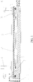
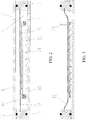
Figure 2 is a state schematic drawing when glass plates to be sealed are vacuumized in theembodiment 1 of the invention; -
Figure 3 is a state schematic drawing when the glass plates to be sealed are sealed in theembodiment 1 of the invention; -
Figure 4 is a state schematic drawing when glass plates to be sealed are vacuumized in theembodiment 2 of the invention; -
Figure 5 is a state schematic drawing when the glass plates to be sealed are sealed in theembodiment 2 of the invention; -
Figure 6 is a state schematic drawing when glass plates to be sealed are vacuumized in theembodiment 3 of the invention; -
Figure 7 is a state schematic drawing when the glass plates to be sealed are sealed in theembodiment 3 of the invention. - The present invention is further described in details in connection with the drawings and the following embodiments.
- The
figure 2 and thefigure 3 show theembodiment 1 of the invention. As shown in the figures, the sealing device comprises abottom plate 13, anannular side wall 14, acover plate 11, apartition plate 12 and aheating device 22; the lower end of theannular side wall 14 is situated on thebottom plate 13 and air-tightly connected with thebottom plate 13 through asealing ring 16, and thesealing ring 16 is arranged on an installation groove formed on theannular side wall 14; thecover plate 11 is covered at the upper end of theannular side wall 14, and the periphery of thecover plate 11 is air-tightly connected with the upper end of theannular side wall 14 through asealing ring 16; the periphery of thepartition plate 12 is air-tightly fixed in an annular groove formed on the inner wall of theannular side wall 14 so as to air-tightly divide the space encircled by thecover plate 11, theannular side wall 14 and thebottom plate 13 into a first closed space and a second closed space, wherein the first closedspace 15 is encircled by thebottom plate 13, theannular side wall 14 and thepartition plate 12, and the second closed space is encircled by thepartition plate 12, theannular side wall 14 and thecover plate 11; and the first and second closed spaces are provided with anair extraction port 17 for vacuumizing respectively, theair extraction port 17 of the first closedspace 15 is formed on thebottom plate 13, and theair extraction port 17 of the second closed space is formed on thecover plate 11. - The
cover plate 11, thebottom plate 13 and theannular side wall 14 are made of metal materials, thepartition plate 12 is made of fluorine rubber, and theheating device 22 is an inductive heating device. - Taking the vacuum glass of two layers as an example, when the vacuum sealing device of the present invention works, firstly, assembling an
upper glass plate 19 and alower glass plate 20 according to a corresponding relationship when the vacuum glass is formed, wherein thelower glass plate 20 is provided with amiddle support 21 for forming the vacuum space; inserting apartition device 18 between the two glass plates so that the two glass plates have a big enough interval to ensure high enough conductance between the two glass plates and enable air molecules to successfully escape during vacuumizing, wherein the interval is preferably more than or equal to 5 millimeters; secondly, as shown in thefigure 2 , putting the assembled glass plates into the first closed space, and simultaneously vacuumizing the two closed spaces in a state that thepartition plate 12 and theupper glass plate 19 are kept in a separate state or thepartition plate 12 does not apply any pressure to theglass plate 19 till the first closed space achieves the required vacuum degree; thirdly, dismantling thepartition device 18, and making theupper glass plate 19 propped on themiddle support 21 and assembled in a to-be-sealed state; fourthly, in the state of keeping the first closed space vacuumized (namely keeping the vacuum degree of the first closed space), stopping vacuumizing the second closed space, connecting the second closed space and the atmosphere, and dismantling thecover plate 11, wherein as shown in thefigure 3 , thepartition plate 12 is deformed under the atmospheric pressure and propped on the whole surface of theupper glass plate 19 and the atmospheric pressure is applied on the glass plates to be sealed; and finally, heating the parts to be sealed of the glass plates to be sealed by using theheating device 23 from the exterior of thepartition plate 12, and completing air-tight sealing on the periphery of the glass plates to be sealed by a metal welding process. - The
heating device 23 can also be a microwave heating device. - When the vacuum glass is processed in a horizontal state by using the sealing device, under the condition that the
cover plate 11 weights enough, the air-tight connection between the cover plate and the floor and between the bottom plate and the annular surrounding plate can be ensured without arranging an additional fixing device between thecover plate 11 and thebottom plate 13, otherwise, a fixing device such as a clamping flange for fixing needs to be arranged between thecover plate 11 and thebottom plate 13. - In addition, the
heating device 23 in theembodiment 1 can be arranged on a known multi-degree-of-freedom moving mechanism (not shown in the figures), and the multi-degree-of-freedom moving mechanism carries theheating device 23 to move along the parts to be sealed of the glass plates to gradually complete welding of the parts to be sealed so as to ensure the welding quality and lighten the working intensity of operators. - The glass plates to be sealed in the
embodiment 1 are directly placed on thebottom plate 13; and when the interval between the upper surface of theupper glass plate 19 and the partition plate is big, the interval can be regulated by arranging a cushion layer or a cushion block with proper thickness on thebottom plate 13 to reduce the deformation of thepartition plate 12 as much as possible and improve the working condition of thepartition plate 12. - The vacuum glass in the
embodiment 1 is a planar vacuum glass; however, when thebottom plate 13 of a curved surface structure, the correspondingannular side wall 14, thepartition plate 12 and thecover plate 11 are adopted, the vacuum glass sealing device of the present invention can also process curved surface vacuum glass products. - The
figure 4 and thefigure 5 show theembodiment 2 of the invention. Compared with theembodiment 1, in theembodiment 2, thepartition plate 12 is arranged in theannular side wall 14 between thebottom plate 13 and thecover plate 11, and the periphery of thepartition plate 12 is air-tightly fixed on and around the inner wall of theannular side wall 14 through anexpansion joint 22 to air-tightly divide the space encircled by thecover plate 11, theannular side wall 14 and thebottom plate 13 into a first closed space and a second closed space; the first closedspace 15 is encircled by thebottom plate 13, theannular side wall 14 and thepartition plate 12; the second closed space is encircled by thepartition plate 12, theannular side wall 14 and thecover plate 11; and the first and second closed spaces are provided with anair extraction port 17 for vacuumizing respectively, theair extraction port 17 of the first closedspace 15 is formed on thebottom plate 13, and theair extraction port 17 of the second closed space is formed on thecover plate 11. - The
expansion joint 22 is an elastomer formed by bending an elastic thin-walled steel plate, as shown in the figure, the section of theexpansion joint 22 is of a curve shape containing an arc section, one side of theexpansion joint 22 is air-tightly connected with the side of thepartition plate 12, and the other side of theexpansion joint 22 is air-tightly fixed in a slot formed on theannular side wall 14. - The
cover plate 11, thebottom plate 13 and theannular side wall 14 are made of metal materials; thepartition plate 12 is made of PP (polypropylene) plate, PC (polycarbonate) plate or other nonmetallic material with proper hardness; and theheating device 23 is an inductive heating device. - Taking the vacuum glass of two layers as an example likewise, when the embodiment 2 of the present invention works, as shown in the
figure 4 , firstly, assembling an upper glass plate 19 and a lower glass plate 20, then putting the assembled glass plates into the first closed place 15, simultaneously vacuumizing the first and second closed spaces, and after the first closed place achieves the required vacuum degree, dismantling the partition device 18 so that the upper glass plate is propped on a middle support 21 and assembled in a to-be-sealed state; secondly, in the state of keeping the first closed space vacuumized (namely keeping the vacuum degree of the first closed space), increasing the air pressure of the second closed space till communicating with the atmosphere, and dismantling the cover plate 11, wherein as shown in thefigure 5 , the partition plate 12 is propped on the surface of the upper glass plate 19 under the action of the pressure difference of the two sides by pressing an expansion joint 22 to deform and the atmospheric pressure is applied on the glass plates to be sealed; and finally, heating the parts to be sealed of the glass plates to be sealed by using a heating device 23 from the exterior of the partition plate 12, and completing air-tight sealing on the periphery of the glass plates to be sealed by a metal welding process. - By selecting the
expansion joint 22 with as low deformation resistance as possible, the pressure applied on theglass plate 19 to be sealed can be approximately as close to the atmospheric pressure as possible. - The
heating device 23 can also be a microwave heating device, and when thebottom plate 13 is made of nonmetal material, theheating device 23 can also heat the glass plates to be sealed from one side of thebottom plate 13. - The
heating device 23 can also be a laser heating device, and then thepartition plate 12 only needs to be processed by adopting a transparent nonmetal material, for example, thepartition plate 12 is manufactured by adopting a transparent PP plate. - In order that the
partition plate 12 is propped on theupper glass plate 19 under the action of the pressure difference of the two sides, besides pressing theexpansion joint 22 to deform, thepartition plate 12 also generates certain deformation at the same time of pressing theexpansion joint 22 to deform, and the partition plate is propped on the surface of theupper glass plate 19 under the condition of mutually superposing the deformation of theexpansion joint 22 on the deformation of thepartition plate 12. - The
figure 4 and thefigure 5 show another embodiment of the invention. As shown in the figures, an expansion joint 22' of a waveform section structure is adopted in theembodiment 3; and compared with theexpansion joint 22 in theembodiment 2, the expansion joint 22' of the waveform section structure can have higher telescopic deformation, so that thepartition plate 12 has higher up and down displacement and the total thickness range of the vacuum glass capable of being sealed by the sealing device is wider. - Specifically, the
embodiment 2 and theembodiment 3 only list the expansion joints of two specific forms, and in addition, the expansion joint with zigzag section shape and other expansion joints with proper section structures can also be adopted. - The embodiments are only used for explaining the invention as defined by the claims.
Claims (14)
- Vacuum glass sealing method, comprising the following steps of:1) conveying glass plates (19, 20) to be sealed into a vacuum chamber, and making the vacuum degree around each glass plate (19, 20) totally as same as that in the vacuum chamber;2) after the vacuum chamber is extracted to the required vacuum degree, assembling a plurality of glass plates (19, 20) into a to-be-sealed state according to a vacuum glass structure;3) applying pressure to the surface of the assembled glass plates (19, 20) to be sealed, and completing air-tight sealing on the periphery of the glass plates (19, 20) to be sealed, wherein the method further comprises the steps of:characterized in that the method further comprising the steps of:a) taking a partition plate (12) as a common side wall, and forming a closed space (15) on two sides of the partition plate (12) within the vacuum chamber respectively;b) when carrying out step 2), assembling a plurality of glass plates (19, 20) according to a corresponding relationship when the vacuum glass is formed, arranging a middle support (21) for forming the vacuum space (15) on at least one of every two adjacent glass plates (19, 20);c) putting the assembled glass plates (19, 20) into one of the closed spaces, and simultaneously vacuumizing the two closed spaces in a state that the partition plate (12) and the glass plate (19) are kept in a separate state, so that the partition plate (12) does not apply any pressure to the glass plate (19) till the closed space of the glass plates (19, 20) achieves the required vacuum degree;d) when carrying out step 3) in the state of keeping the closed space of the glass plates (19, 20) vacuumized, increasing the air pressure of the other closed space so that the partition plate (12) is deformed under the action of pressure difference of two sides and propped on the surface of the glass plates (19, 20) to be sealed, and then applying pressure to the glass plates (19, 20) to be sealed;e) heating the parts to be sealed of the glass plates (19, 20) to be sealed by using a heating device (23) from the exterior of the closed space of the glass plates (19, 20) to be sealed, and completing air-tight sealing on the periphery of the vacuum glass by a metal welding process, wherein the used heating device (23) is an inductive heating device or a microwave heating device,- during the step of assembling a plurality of glass plates (19, 20), inserting a partition device (18) so that a big enough interval is formed between the every two adjacent glass plates (19, 20) to ensure high enough conductance between the two adjacent glass plates (19, 20) high enough and enable the air molecules to successfully escape during vacuumizing; and- after the step of putting the assembled glass plates (19, 20) into one of the closed spaces, dismantling the partition device (18), and making the every two adjacent glass plates (19, 20) propped on the middle support (21) amid and assembled in the to-be-sealed state.
- Method according to claim 1, characterized in that in the step 3), maintaining the vacuum degree in the vacuum chamber unchangeable, applying pressure to the surface of the assembled glass plates (19, 20) to be sealed, and completing air-tight sealing on the periphery of the glass plates (19, 20) to be sealed in the state.
- Method according to claim 1 or 2, characterized in that in the step 3), the pressure applied to the surface of the assembled glass plates (19, 20) to be sealed is equal to or as close as possible to atmospheric pressure.
- Method according to any of the preceding claims, characterized in that in the step d), the pressure applied to the glass plates (19, 20) to be sealed is equal to or as close as possible to atmospheric pressure.
- Vacuum glass sealing device, comprising a bottom plate (13), an annular side wall (14), a cover plate (11), a partition plate (12) and a heating device (23), wherein the lower end of the annular side wall (14) is situated on the bottom plate (13) and air-tightly connected with the bottom plate (13); the cover plate (11) is air-tightly covered at the upper end of the annular side wall (14); the partition plate (12) is arranged in the annular side wall (14) between the bottom plate (13) and the cover plate (11); after the periphery of the partition plate (12) is air-tightly connected with the inner surface of the annular side wall (14), the partition plate (12) divides the space encircled by the bottom plate (13), the annular side wall (14) and the cover plate (11) into a first closed space (15) and a second closed space; the two closed spaces are provided with an air extraction port (17) for vacuumizing respectively, wherein- the first closed space (15) positioned between the partition plate (12) and the bottom plate (13) is used for placing the glass plates (19, 20) to be sealed;- the second closed space positioned between the partition plate (12) and the cover plate (11) is used for controlling the working state of the partition plate (12):a) synchronously vacuumizing the second closed space and the first closed space (15) so that the partition plate (12) is separated from the glass plates (19, 20) to be sealed in the first closed space (15) or does not apply pressure to the glass plates (19, 20) to be sealed; andb) in the state of keeping the first closed space (15) vacuumized, increasing the air pressure of the second closed space so that the partition plate (12) is propped on the glass plates (19, 20) to be sealed under the action of pressure difference of two sides, further increasing the air pressure of the second closed space, and applying pressure to the glass plates (19, 20) to be sealed;- the heating device (23) is used for heating the parts to be sealed of the glass plates (19, 20) to be sealed from the exterior of the first closed space (15), and completing air-tight sealing of the parts to be sealed by a metal welding process,wherein the periphery of the partition plate (12) is air-tightly fixed on and around the annular side wall (14) through an expansion joint (22); the expansion joint (22) is an elastomer formed by bending an elastic thin-walled material, the cross section of the expansion joint (22) is of a zigzag shape or a curve shape containing an arc section or a compound shape containing a zigzag structure and a curve section, the expansion joint (22) is deformed by stretching or compressing of the shape of the section therefore, one side of the expansion joint (22) is air-tightly connected with the side of the partition plate (12), and the other side of the expansion joint (22) is air-tightly fixed on the annular side wall (14); and in the b) state, the partition plate (12) is propped on the glass plates (19, 20) to be sealed under the action of the pressure difference of the two sides by simultaneous superposition of deformation of the expansion joint (22) for pressing the periphery of the partition plate (12) and personal deformation,
characterized in that the sealing device further comprises a partition device (18) movable between an insert position in which an interval is formed between two adjacent glass plates (19, 20) for vacuumizing and a dismantled position in which the glass plates (19, 20) are propped on the middle support (21) and assembled in a to-be-sealed state, and. - The sealing device according to the claim 5, characterized in that the second closed space is communicated with the atmosphere to increase the air pressure.
- The sealing device according to the claim 6, characterized in that the pressure applied to the glass plates (19, 20) to be sealed is equal to or as close as possible to atmospheric pressure.
- The sealing device according to any of claims 5-7, characterized in that the air extraction port (17) of the first closed space (15) is formed on the bottom plate (13) and/or the annular side wall (14), and the air extraction port (17) of the second closed space is formed on the cover plate (11) and/or the annular side wall (14).
- The sealing device according to any of claims 5-8, characterized in that the bottom plate (13) is air-tightly connected with the lower end of the annular side wall (14) through a sealing ring (16), the cover plate (11) is air-tightly connected with the upper end of the annular side wall (14) through a sealing ring (16), and the sealing rings (16) are arranged in sealing ring installation grooves formed on the annular side wall (14) and/or the bottom plate (13) and the cover plate (11).
- The sealing device according to any of claims 5-9, characterized in that the heating device (23) is an inductive heating device or a microwave heating device, and correspondingly, the partition plate (12) positioned between the heating device (23) and the glass plates (19, 20) to be sealed or the bottom plate (13) is made of nonmetallic material.
- The sealing device according to any of claims 5-10, characterized in that the periphery of the partition plate (12) is air-tightly fixed on the annular side wall (14), and in the b) state, the partition plate (12) is propped on the glass plates (19, 20) to be sealed under the action of pressure difference of two sides by means of personal deformation.
- The sealing device according to any of claims 5-11, characterized in that the partition plate (12) is made of fluorine rubber.
- The sealing device according to any of claims 5-12, characterized in that the partition plate (12) is made of PP (polypropylene) plate or PC (polycarbonate) plate.
- The sealing device according to any of claims 5-13, characterized in that the heating device (23) is a laser heating device, and the partition plate (12) positioned between the heating device (23) and the glass plates (19, 20) to be sealed or the bottom plate (13) is made of transparent material.
Priority Applications (1)
| Application Number | Priority Date | Filing Date | Title |
|---|---|---|---|
| PL11869133T PL2729422T3 (en) | 2011-07-05 | 2011-08-09 | Vacuum glass sealing method and device |
Applications Claiming Priority (2)
| Application Number | Priority Date | Filing Date | Title |
|---|---|---|---|
| CN201110186356.5A CN102863158B (en) | 2011-07-05 | 2011-07-05 | Vacuum glass sealing method and device |
| PCT/CN2011/078161 WO2013004038A1 (en) | 2011-07-05 | 2011-08-09 | Vacuum glass sealing method and device |
Publications (3)
| Publication Number | Publication Date |
|---|---|
| EP2729422A1 EP2729422A1 (en) | 2014-05-14 |
| EP2729422A4 EP2729422A4 (en) | 2015-06-24 |
| EP2729422B1 true EP2729422B1 (en) | 2017-10-11 |
Family
ID=47436469
Family Applications (1)
| Application Number | Title | Priority Date | Filing Date |
|---|---|---|---|
| EP11869133.6A Active EP2729422B1 (en) | 2011-07-05 | 2011-08-09 | Vacuum glass sealing method and device |
Country Status (14)
| Country | Link |
|---|---|
| US (1) | US9266766B2 (en) |
| EP (1) | EP2729422B1 (en) |
| JP (1) | JP5887406B2 (en) |
| KR (1) | KR101612803B1 (en) |
| CN (1) | CN102863158B (en) |
| AU (1) | AU2011372430B2 (en) |
| BR (1) | BR112014000019B1 (en) |
| CA (1) | CA2839178C (en) |
| ES (1) | ES2647439T3 (en) |
| MX (1) | MX348700B (en) |
| PL (1) | PL2729422T3 (en) |
| RU (1) | RU2555724C1 (en) |
| UA (1) | UA108801C2 (en) |
| WO (1) | WO2013004038A1 (en) |
Families Citing this family (104)
| Publication number | Priority date | Publication date | Assignee | Title |
|---|---|---|---|---|
| CN102476926B (en) * | 2010-11-23 | 2013-12-18 | 洛阳兰迪玻璃机器股份有限公司 | Vacuum glass sealing device |
| CN102617025B (en) * | 2011-01-31 | 2014-06-25 | 洛阳兰迪玻璃机器股份有限公司 | Method for acquiring vacuum during making vacuum glass member |
| CN104291655A (en) * | 2013-07-17 | 2015-01-21 | 戴长虹 | Flat double-vacuum-layer glass having sealing bar and mounting hole and being welded by glass |
| CN104743930A (en) * | 2013-12-25 | 2015-07-01 | 戴长虹 | Glass-welded plain double-vacuum-layer glass provided with edges sealed by sealing strips and provided with mounting hole(s) |
| CN104743905A (en) * | 2013-12-25 | 2015-07-01 | 戴长虹 | Metal-welded sealed convex double-vacuum-layer glass with edges sealed by sealing grooves and sealing strips |
| CN104743820A (en) * | 2013-12-25 | 2015-07-01 | 戴长虹 | Glass-welded plain vacuum glass provided with edges sealed by sealing grooves and provided with mounting hole(s) |
| CN104743784A (en) * | 2013-12-25 | 2015-07-01 | 戴长虹 | Glass-welded convex double-vacuum-layer glass provided with edges sealed by sealing strips and provided with mounting hole(s) |
| CN104743846A (en) * | 2013-12-25 | 2015-07-01 | 戴长虹 | Glass-welded sealed convex vacuum glass with edges and extraction openings sealed by sealing strips and grooves and production method |
| CN104743844A (en) * | 2013-12-25 | 2015-07-01 | 戴长虹 | Plane double-vacuum-layer glass by glass welding at sealed edge of sealing grooves and strips and production method thereof |
| CN104743899A (en) * | 2013-12-25 | 2015-07-01 | 戴长虹 | Metal-welded sealed convex double-vacuum-layer glass with edges sealed by sealing grooves and manufacturing method thereof |
| CN104743915A (en) * | 2013-12-25 | 2015-07-01 | 戴长虹 | Metal-welded convex vacuum glass provided with edges sealed by sealing strips and manufacturing method thereof |
| CN104743847A (en) * | 2013-12-25 | 2015-07-01 | 戴长虹 | Convex vacuum glass by glass welding at sealed edge of sealing groove and production method thereof |
| CN104743933A (en) * | 2013-12-25 | 2015-07-01 | 戴长虹 | Metal-welded plain vacuum glass with installing holes and edge sealed by sealing strips |
| CN104743823A (en) * | 2013-12-25 | 2015-07-01 | 戴长虹 | Glass-welded plain vacuum glass provided with edges sealed by sealing strips and provided with mounting hole(s) |
| CN104743798A (en) * | 2013-12-25 | 2015-07-01 | 戴长虹 | Metal-welded plain double-vacuum-layer glass provided with edges sealed by sealing grooves and manufacturing method thereof |
| CN104743827A (en) * | 2013-12-25 | 2015-07-01 | 戴长虹 | Glass-welded sealed convex double-vacuum-layer glass with edges sealed by sealing grooves and manufacturing method thereof |
| CN104743853A (en) * | 2013-12-25 | 2015-07-01 | 戴长虹 | Glass-welded convex double-vacuum-layer glass with edge sealed by sealing strip and production method thereof |
| CN104743796A (en) * | 2013-12-25 | 2015-07-01 | 戴长虹 | High-temperature-sheet-combination plain vacuum glass provided with edges sealed by sealing grooves and sealing strips and provided with mounting hole(s) |
| CN104743916A (en) * | 2013-12-25 | 2015-07-01 | 戴长虹 | Metal-welded plain vacuum glass provided with edges sealed by sealing grooves and manufacturing method thereof |
| CN104743828A (en) * | 2013-12-25 | 2015-07-01 | 戴长虹 | Glass-welded sealed convex vacuum glass with edges sealed by sealing grooves and manufacturing method thereof |
| CN104743913A (en) * | 2013-12-25 | 2015-07-01 | 戴长虹 | Metal-welded plain double-vacuum-layer glass provided with edges sealed by sealing strips and provided with mounting hole(s) |
| CN104743912A (en) * | 2013-12-25 | 2015-07-01 | 戴长虹 | Metal-welded convex vacuum glass provided with edges sealed by sealing strips and provided with mounting hole(s) |
| CN104743852A (en) * | 2013-12-25 | 2015-07-01 | 戴长虹 | Glass-welded convex vacuum glass having installing holes with edge sealed by sealing strips |
| CN104743908A (en) * | 2013-12-25 | 2015-07-01 | 戴长虹 | Metal-welded convex double-vacuum-layer glass provided with edges sealed by sealing strips and provided with mounting hole(s) |
| CN104743800A (en) * | 2013-12-25 | 2015-07-01 | 戴长虹 | Glass-welded sealed plain vacuum glass with edges sealed by sealing strips and manufacturing method thereof |
| CN104743805A (en) * | 2013-12-25 | 2015-07-01 | 戴长虹 | High-temperature-sheet-combination sealed convex vacuum glass with edges sealed by sealing grooves and sealing strips and manufacturing method thereof |
| CN104743904A (en) * | 2013-12-25 | 2015-07-01 | 戴长虹 | Metal-welded sealed plain vacuum glass with edges sealed by sealing grooves and sealing strips and manufacturing method thereof |
| CN104743781A (en) * | 2013-12-25 | 2015-07-01 | 戴长虹 | High-temperature-sheet-combination sealed convex double-vacuum-layer glass provided with edges sealed by sealing strips and manufacturing method thereof |
| CN104743842A (en) * | 2013-12-25 | 2015-07-01 | 戴长虹 | Vacuum glass laminated at high temperature and production method thereof |
| CN104743782A (en) * | 2013-12-25 | 2015-07-01 | 戴长虹 | High-temperature-sheet-combination sealed convex vacuum glass with edges sealed by sealing strips and manufacturing method thereof |
| CN104743814A (en) * | 2013-12-25 | 2015-07-01 | 戴长虹 | Glass-welded convex vacuum glass provided with edges sealed by sealing grooves and sealing strips and provided with mounting hole(s) |
| CN104743821A (en) * | 2013-12-25 | 2015-07-01 | 戴长虹 | High-temperature-sheet-combination sealed convex double-vacuum-layer glass with edges sealed by sealing grooves and manufacturing method thereof |
| CN104743910A (en) * | 2013-12-25 | 2015-07-01 | 戴长虹 | Metal-welded convex vacuum glass provided with edges sealed by sealing grooves and manufacturing method thereof |
| CN104743902A (en) * | 2013-12-25 | 2015-07-01 | 戴长虹 | Metal-welded sealed plain vacuum glass with edges sealed by sealing strips and manufacturing method thereof |
| CN104743838A (en) * | 2013-12-25 | 2015-07-01 | 戴长虹 | Glass-welded convex double-vacuum-layer glass with edges sealed by sealing strips and manufacturing method thereof |
| CN104743906A (en) * | 2013-12-25 | 2015-07-01 | 戴长虹 | Metal-welded convex double-vacuum-layer glass provided with edges sealed by sealing strips and provided with mounting hole(s) |
| CN104743927A (en) * | 2013-12-25 | 2015-07-01 | 戴长虹 | Metal-welded convex vacuum glass provided with edges sealed by sealing grooves and provided with mounting hole(s) |
| CN104743809A (en) * | 2013-12-25 | 2015-07-01 | 戴长虹 | High-temperature-sheet-combination sealed plain double-vacuum-layer glass with edges sealed by sealing grooves and manufacturing method thereof |
| CN104743816A (en) * | 2013-12-25 | 2015-07-01 | 戴长虹 | High-temperature-sheet-combination plain double-vacuum-layer glass provided with edges sealed by sealing strips and provided with mounting hole(s) |
| CN104743791A (en) * | 2013-12-25 | 2015-07-01 | 戴长虹 | Glass-welded plain vacuum glass provided with edges sealed by sealing grooves and sealing strips and provided with mounting hole(s) |
| CN104743849A (en) * | 2013-12-25 | 2015-07-01 | 戴长虹 | Glass-welded convex double-vacuum-layer glass with edge sealed by sealing grooves and strips and production method thereof |
| CN104743829A (en) * | 2013-12-25 | 2015-07-01 | 戴长虹 | High-temperature-sheet-combination plain vacuum glass provided with edges sealed by sealing strips and provided with mounting hole(s) |
| CN104743826A (en) * | 2013-12-25 | 2015-07-01 | 戴长虹 | Glass-welded sealed plain vacuum glass with edges sealed by sealing grooves and sealing strips and manufacturing method thereof |
| CN104743936A (en) * | 2013-12-25 | 2015-07-01 | 戴长虹 | Metal-welded convex double-vacuum-layer glass with installing holes at edge sealed by sealing grooves |
| CN104743896A (en) * | 2013-12-25 | 2015-07-01 | 戴长虹 | Metal-welded sealed plain double-vacuum-layer glass with edges sealed by sealing grooves and manufacturing method thereof |
| CN104743848A (en) * | 2013-12-25 | 2015-07-01 | 戴长虹 | Glass-welded convex surface double-vacuum-layer glass with edge sealed by sealing grooves and production method thereof |
| CN104743918A (en) * | 2013-12-25 | 2015-07-01 | 戴长虹 | Metal-welded plain vacuum glass provided with edges sealed by sealing grooves and sealing strips and manufacturing method thereof |
| CN104743935A (en) * | 2013-12-25 | 2015-07-01 | 戴长虹 | Metal-welded plane vacuum glass having installing holes with edge sealed by sealing grooves and strips |
| CN104743808A (en) * | 2013-12-25 | 2015-07-01 | 戴长虹 | High-temperature-sheet-combination plain vacuum glass provided with edges sealed by sealing grooves and provided with mounting hole(s) |
| CN104743801A (en) * | 2013-12-25 | 2015-07-01 | 戴长虹 | Glass-welded convex vacuum glass provided with edges sealed by sealing strips and provided with mounting hole(s) |
| CN104743940A (en) * | 2013-12-25 | 2015-07-01 | 戴长虹 | Metal-welded convex vacuum glass having installing holes by metal welding at sealed edge of sealing strips |
| CN104743811A (en) * | 2013-12-25 | 2015-07-01 | 戴长虹 | Glass-welded sealed convex double-vacuum-layer glass with edges sealed by sealing grooves and sealing strips |
| CN104743914A (en) * | 2013-12-25 | 2015-07-01 | 戴长虹 | Metal-welded convex double-vacuum-layer glass provided with edges sealed by sealing grooves and sealing strips and provided with mounting hole(s) |
| CN104743783A (en) * | 2013-12-25 | 2015-07-01 | 戴长虹 | Metal-welded sealed convex vacuum glass with edges sealed by sealing grooves and manufacturing method thereof |
| CN104743807A (en) * | 2013-12-25 | 2015-07-01 | 戴长虹 | High-temperature-sheet-combination sealed plain double-vacuum-layer glass provided with edges sealed by sealing grooves and sealing strips |
| CN104743786A (en) * | 2013-12-25 | 2015-07-01 | 戴长虹 | Glass-welded sealed plain double-vacuum-layer glass with edges sealed by sealing grooves and manufacturing method thereof |
| CN104743895A (en) * | 2013-12-25 | 2015-07-01 | 戴长虹 | Metal-welded sealed convex vacuum glass with edges sealed by sealing grooves and sealing strips and manufacturing method thereof |
| CN104743793A (en) * | 2013-12-25 | 2015-07-01 | 戴长虹 | Glass-welded convex double-vacuum-layer glass provided with edges sealed by sealing grooves and provided with mounting hole(s) |
| CN104743788A (en) * | 2013-12-25 | 2015-07-01 | 戴长虹 | High-temperature-sheet-combination sealed convex vacuum glass with edges sealed by sealing grooves and manufacturing method thereof |
| CN104743917A (en) * | 2013-12-25 | 2015-07-01 | 戴长虹 | Metal-welded convex double-vacuum-layer glass provided with edges sealed by sealing grooves and manufacturing method thereof |
| CN104743787A (en) * | 2013-12-25 | 2015-07-01 | 戴长虹 | High-temperature-sheet-combination sealed plain vacuum glass with edges sealed by sealing grooves and sealing strips and manufacturing method thereof |
| CN104743939A (en) * | 2013-12-25 | 2015-07-01 | 戴长虹 | Metal-welded plane vacuum glass with installing holes with edge sealed by sealing grooves |
| CN104743794A (en) * | 2013-12-25 | 2015-07-01 | 戴长虹 | High-temperature-sheet-combination plain double-vacuum-layer glass provided with edges sealed by sealing grooves and provided with mounting hole(s) |
| CN104743903A (en) * | 2013-12-25 | 2015-07-01 | 戴长虹 | Metal-welded sealed convex double-vacuum-layer glass with edges sealed by sealing strips and manufacturing method thereof |
| CN104743909A (en) * | 2013-12-25 | 2015-07-01 | 戴长虹 | Metal-welded convex vacuum glass provided with edges sealed by sealing strips and sealing grooves and provided with mounting hole(s) |
| CN104743790A (en) * | 2013-12-25 | 2015-07-01 | 戴长虹 | Glass-welded convex double-vacuum-layer glass provided with edges sealed by sealing grooves and provided with mounting hole(s) |
| CN104743806A (en) * | 2013-12-25 | 2015-07-01 | 戴长虹 | High-temperature-sheet-combination sealed plain vacuum glass provided with edges sealed by sealing strips and manufacturing method thereof |
| CN104743795A (en) * | 2013-12-25 | 2015-07-01 | 戴长虹 | High-temperature-sheet-combination convex double-vacuum-layer glass provided with edges sealed by sealing grooves and provided with mounting hole(s) |
| CN104743928A (en) * | 2013-12-25 | 2015-07-01 | 戴长虹 | Metal-welded convex double-vacuum-layer glass provided with edges sealed by sealing grooves and provided with mounting hole(s) |
| CN104743810A (en) * | 2013-12-25 | 2015-07-01 | 戴长虹 | High-temperature-sheet-combination sealed plain double-vacuum-layer glass provided with edges sealed by sealing strips and manufacturing method thereof |
| CN104743932A (en) * | 2013-12-25 | 2015-07-01 | 戴长虹 | Plane double-vacuum-layer glass by metal welding at sealed edge of sealing grooves and strips and production method thereof |
| CN104743802A (en) * | 2013-12-25 | 2015-07-01 | 戴长虹 | High-temperature-sheet-combination convex double-vacuum-layer glass provided with edges sealed by sealing strips and provided with mounting hole(s) |
| CN104743898A (en) * | 2013-12-25 | 2015-07-01 | 戴长虹 | Metal-welded sealed plain double-vacuum-layer glass with edges sealed by sealing grooves and sealing strips |
| CN104743900A (en) * | 2013-12-25 | 2015-07-01 | 戴长虹 | Metal-welded sealed convex vacuum glass with edges sealed by sealing strips and manufacturing method thereof |
| CN104743822A (en) * | 2013-12-25 | 2015-07-01 | 戴长虹 | Glass-welded convex double-vacuum-layer glass provided with edges sealed by sealing grooves and sealing strips and provided with mounting hole(s) |
| CN104743901A (en) * | 2013-12-25 | 2015-07-01 | 戴长虹 | Metal-welded sealed plain double-vacuum-layer glass with edges sealed by sealing strips and manufacturing method thereof |
| CN104743923A (en) * | 2013-12-25 | 2015-07-01 | 戴长虹 | Metal-welded convex vacuum glass provided with edges sealed by sealing grooves and sealing strips and provided with mounting hole(s) |
| CN104743929A (en) * | 2013-12-25 | 2015-07-01 | 戴长虹 | Glass-welded sealed plain double-vacuum-layer glass with edges sealed by sealing grooves and sealing strips |
| CN104743843A (en) * | 2013-12-25 | 2015-07-01 | 戴长虹 | Plain vacuum glass with installing holes by glass welding at sealed edge of sealing strip |
| CN104743824A (en) * | 2013-12-25 | 2015-07-01 | 戴长虹 | Glass-welded convex vacuum glass provided with edges sealed by sealing grooves and provided with mounting hole(s) |
| CN104743825A (en) * | 2013-12-25 | 2015-07-01 | 戴长虹 | High-temperature-sheet-combination convex vacuum glass provided with edges sealed by sealing grooves and provided with mounting hole(s) |
| CN104743792A (en) * | 2013-12-25 | 2015-07-01 | 戴长虹 | Glass-welded plain double-vacuum-layer glass provided with edges sealed by sealing grooves and sealing strips and provided with mounting hole(s) |
| CN104743931A (en) * | 2013-12-25 | 2015-07-01 | 戴长虹 | Plane double-vacuum-layer glass by metal welding at sealed edge of sealing strip and production method thereof |
| CN104743813A (en) * | 2013-12-25 | 2015-07-01 | 戴长虹 | Glass-welded convex vacuum glass provided with edges sealed by sealing grooves and provided with mounting hole(s) |
| CN104743804A (en) * | 2013-12-25 | 2015-07-01 | 戴长虹 | High-temperature-sheet-combination sealed convex double-vacuum-layer glass with edges sealed by sealing grooves and sealing strips |
| CN104743897A (en) * | 2013-12-25 | 2015-07-01 | 戴长虹 | Metal-welded sealed plain vacuum glass with edges sealed by sealing grooves and manufacturing method thereof |
| CN104743845A (en) * | 2013-12-25 | 2015-07-01 | 戴长虹 | Convex vacuum glass by glass welding at sealed edge of sealing grooves and strips and production method thereof |
| CN104743799A (en) * | 2013-12-25 | 2015-07-01 | 戴长虹 | Glass-welded sealed plain double-vacuum-layer glass with edges sealed by sealing strips and manufacturing method thereof |
| CN104743785A (en) * | 2013-12-25 | 2015-07-01 | 戴长虹 | Glass-welded plain double-vacuum-layer glass provided with edges sealed by sealing grooves and provided with mounting hole(s) |
| CN104743919A (en) * | 2013-12-25 | 2015-07-01 | 戴长虹 | Metal-welded plain double-vacuum-layer glass provided with edges sealed by sealing strips and sealing grooves and provided with mounting hole(s) |
| KR102353034B1 (en) | 2014-08-11 | 2022-01-19 | 삼성디스플레이 주식회사 | Flexible orgainic light emitting diode |
| US10704320B2 (en) | 2015-08-20 | 2020-07-07 | Vkr Holding A/S | Method for producing a VIG unit having an improved temperature profile |
| CN105439480A (en) * | 2015-12-15 | 2016-03-30 | 洛阳兰迪玻璃机器股份有限公司 | Metal sealing method of vacuum glass |
| CN105502968B (en) * | 2015-12-15 | 2018-07-24 | 洛阳兰迪玻璃机器股份有限公司 | A kind of metal sealing method of vacuum glass |
| WO2017169252A1 (en) * | 2016-03-31 | 2017-10-05 | パナソニックIpマネジメント株式会社 | Glass panel unit manufacturing method |
| CN106869701B (en) * | 2016-07-18 | 2018-09-04 | 青岛金晶股份有限公司 | A kind of hollow glass component of automatic adjustable pressure |
| CN109415253B (en) * | 2017-10-25 | 2022-04-22 | 深圳孔雀科技开发有限公司 | Sealing method of flat vacuum glass |
| CN109665704B (en) * | 2018-12-18 | 2023-12-15 | 山西利虎玻璃(集团)有限公司 | Glass forming process |
| CN109626802B (en) * | 2018-12-18 | 2023-10-03 | 泗县微腾知识产权运营有限公司 | A kind of glass high-temperature pressing combined with forming process palletizing system |
| CN109553284B (en) * | 2019-01-02 | 2023-07-25 | 洛阳八佳电气科技股份有限公司 | Vacuum glass plane sealing method |
| CN111122098A (en) * | 2019-12-13 | 2020-05-08 | 武汉航空仪表有限责任公司 | Sealing device and sealing method for negative pressure bin test pipeline wall penetration |
| RU2766979C1 (en) * | 2020-12-02 | 2022-03-16 | Федеральное Государственное Автономное Образовательное Учреждение Высшего Образования "Самарский Национальный Исследовательский Университет Имени Академика С.П. Королева" (Самарский Университет) | Method for thermal connection of glass plates with microstructures on one of the surfaces thereof |
| CN114192532B (en) * | 2021-12-01 | 2022-07-08 | 安徽玻扬节能钢化玻璃有限公司 | Cavity glass pastes processingequipment |
| CN116177907B (en) * | 2022-10-31 | 2025-08-01 | 江苏博韵低维材料科技有限公司 | Vacuumizing box for mass production of vacuum glass and vacuum glass production process |
Family Cites Families (17)
| Publication number | Priority date | Publication date | Assignee | Title |
|---|---|---|---|---|
| JPS5957221A (en) * | 1982-09-28 | 1984-04-02 | Asahi Glass Co Ltd | Production of display element |
| US4691995A (en) * | 1985-07-15 | 1987-09-08 | Semiconductor Energy Laboratory Co., Ltd. | Liquid crystal filling device |
| JP2530853B2 (en) * | 1987-06-12 | 1996-09-04 | 松下電器産業株式会社 | Liquid crystal display element manufacturing method |
| SU1655919A1 (en) * | 1988-11-30 | 1991-06-15 | Орловское Государственное Специальное Проектно-Конструкторское Бюро Стекольного Машиностроения | Multiple glass unit vacuumizing device |
| US5240488A (en) * | 1992-08-14 | 1993-08-31 | At&T Bell Laboratories | Manufacture of vitreous silica product via a sol-gel process using a polymer additive |
| JPH10152347A (en) * | 1996-11-20 | 1998-06-09 | Nippon Sheet Glass Co Ltd | Multiple glass |
| AU5406399A (en) * | 1999-08-27 | 2001-03-26 | Qingdao Synergy Technology Appliance Co., Ltd. | The method for manufacturing vacuum glazing and its application mechanical system |
| EP1221526A1 (en) * | 2001-01-09 | 2002-07-10 | Emil BÄCHLI | Method and equipment for making heat-insulating construction and/or lighting elements |
| WO2003095388A1 (en) | 2002-05-13 | 2003-11-20 | Nippon Sheet Glass Co., Ltd. | Depressurizing container for glass panel |
| CN2869008Y (en) * | 2006-02-10 | 2007-02-14 | 马长青 | Manufacturing equipment for processing photosensitive sealed vacuum glass by vacuum chamber |
| CN101050056A (en) * | 2006-04-05 | 2007-10-10 | 罗建超 | New method and equipment for preparing vacuum glass faceplate |
| CN101148313B (en) * | 2006-09-20 | 2011-01-12 | 黄家军 | One-step forming vacuum glass and its manufacturing method and device |
| US8460493B2 (en) * | 2007-12-14 | 2013-06-11 | Guardian Industries Corp. | Evacuation and port sealing techniques for vacuum insulating glass units, and/or vacuum oven for accomplishing the same |
| CN101298370B (en) * | 2008-03-21 | 2011-06-08 | 胡屹博 | Method for making low-temperature adhesive plate vacuum glass and apparatus thereof |
| JP2010009029A (en) * | 2008-05-26 | 2010-01-14 | Canon Inc | Method of producing optical element, and optical element |
| JP5062897B2 (en) * | 2008-06-06 | 2012-10-31 | クライムプロダクツ株式会社 | Work bonding machine |
| CN102079619B (en) * | 2009-11-27 | 2012-02-15 | 洛阳兰迪玻璃机器股份有限公司 | Glass plate combination sealing method |
-
2011
- 2011-07-05 CN CN201110186356.5A patent/CN102863158B/en active Active
- 2011-08-09 EP EP11869133.6A patent/EP2729422B1/en active Active
- 2011-08-09 AU AU2011372430A patent/AU2011372430B2/en active Active
- 2011-08-09 KR KR1020147000218A patent/KR101612803B1/en active Active
- 2011-08-09 RU RU2013157681/03A patent/RU2555724C1/en active
- 2011-08-09 ES ES11869133.6T patent/ES2647439T3/en active Active
- 2011-08-09 PL PL11869133T patent/PL2729422T3/en unknown
- 2011-08-09 JP JP2014517390A patent/JP5887406B2/en active Active
- 2011-08-09 CA CA2839178A patent/CA2839178C/en active Active
- 2011-08-09 BR BR112014000019-0A patent/BR112014000019B1/en active IP Right Grant
- 2011-08-09 WO PCT/CN2011/078161 patent/WO2013004038A1/en not_active Ceased
- 2011-08-09 MX MX2013015337A patent/MX348700B/en active IP Right Grant
- 2011-08-09 US US14/124,885 patent/US9266766B2/en active Active
- 2011-09-08 UA UAA201314188A patent/UA108801C2/en unknown
Non-Patent Citations (1)
| Title |
|---|
| None * |
Also Published As
| Publication number | Publication date |
|---|---|
| EP2729422A1 (en) | 2014-05-14 |
| BR112014000019B1 (en) | 2020-10-27 |
| JP5887406B2 (en) | 2016-03-16 |
| CN102863158B (en) | 2014-09-10 |
| EP2729422A4 (en) | 2015-06-24 |
| MX348700B (en) | 2017-06-26 |
| US9266766B2 (en) | 2016-02-23 |
| WO2013004038A1 (en) | 2013-01-10 |
| US20140116092A1 (en) | 2014-05-01 |
| CA2839178A1 (en) | 2013-01-10 |
| UA108801C2 (en) | 2015-06-10 |
| CN102863158A (en) | 2013-01-09 |
| ES2647439T3 (en) | 2017-12-21 |
| BR112014000019A2 (en) | 2017-02-07 |
| AU2011372430B2 (en) | 2015-04-16 |
| AU2011372430A1 (en) | 2014-01-16 |
| PL2729422T3 (en) | 2018-03-30 |
| CA2839178C (en) | 2015-11-03 |
| KR101612803B1 (en) | 2016-04-15 |
| KR20140039262A (en) | 2014-04-01 |
| RU2555724C1 (en) | 2015-07-10 |
| JP2014520065A (en) | 2014-08-21 |
| MX2013015337A (en) | 2014-02-20 |
Similar Documents
| Publication | Publication Date | Title |
|---|---|---|
| US9266766B2 (en) | Vacuum glass sealing method and device | |
| EP2643273B1 (en) | Vacuum glass sealing device | |
| US7195476B2 (en) | Heating-type vacuum press apparatus | |
| KR101412512B1 (en) | Apparatus for manufacturing vacuum glass panel and method for manufacturing thereof | |
| US4450034A (en) | Laminator for large workpieces | |
| JP6871107B2 (en) | Thermoforming equipment and thermoforming method | |
| JP5585945B2 (en) | Seal structure and joining device | |
| CN104003629A (en) | Vacuum glass sealing method | |
| WO2012118295A2 (en) | Autoclave | |
| CN106042594B (en) | The full laminating apparatus of multi cylinder and method | |
| JP2010169896A (en) | Processing apparatus | |
| JP2021511225A5 (en) | ||
| CN116252467A (en) | Vacuum thermal pressure difference laminating device | |
| CA2966027C (en) | Energy-saving plate and method for manufacturing the same | |
| JP5451432B2 (en) | Work bonding machine | |
| NO20240852A1 (en) | Anti-ballistic plate consolidation tool and appurtenant method | |
| Jirásko et al. | Static numerical analysis of a hydraulic curing press | |
| JP2001313407A (en) | Laminating equipment | |
| JP2014159122A (en) | Hybrid panel manufacturing apparatus | |
| JP2002072903A (en) | Method and apparatus for manufacturing display panel | |
| JP2002144431A (en) | Laminating equipment | |
| KR20060036594A (en) | Vacuum joining device and joining method for large area bonding materials | |
| WO2012118290A2 (en) | Laminating apparatus for panel as electronic component |
Legal Events
| Date | Code | Title | Description |
|---|---|---|---|
| PUAI | Public reference made under article 153(3) epc to a published international application that has entered the european phase |
Free format text: ORIGINAL CODE: 0009012 |
|
| 17P | Request for examination filed |
Effective date: 20140205 |
|
| AK | Designated contracting states |
Kind code of ref document: A1 Designated state(s): AL AT BE BG CH CY CZ DE DK EE ES FI FR GB GR HR HU IE IS IT LI LT LU LV MC MK MT NL NO PL PT RO RS SE SI SK SM TR |
|
| DAX | Request for extension of the european patent (deleted) | ||
| RA4 | Supplementary search report drawn up and despatched (corrected) |
Effective date: 20150528 |
|
| RIC1 | Information provided on ipc code assigned before grant |
Ipc: E06B 3/66 20060101ALN20150521BHEP Ipc: E06B 3/677 20060101ALI20150521BHEP Ipc: C03C 27/08 20060101ALN20150521BHEP Ipc: C03B 23/24 20060101AFI20150521BHEP |
|
| GRAP | Despatch of communication of intention to grant a patent |
Free format text: ORIGINAL CODE: EPIDOSNIGR1 |
|
| RIC1 | Information provided on ipc code assigned before grant |
Ipc: C03C 27/08 20060101ALN20170314BHEP Ipc: E06B 3/677 20060101ALI20170314BHEP Ipc: C03B 23/24 20060101AFI20170314BHEP Ipc: E06B 3/66 20060101ALN20170314BHEP |
|
| RIC1 | Information provided on ipc code assigned before grant |
Ipc: C03B 23/24 20060101AFI20170317BHEP Ipc: C03C 27/08 20060101ALN20170317BHEP Ipc: E06B 3/66 20060101ALN20170317BHEP Ipc: E06B 3/677 20060101ALI20170317BHEP |
|
| INTG | Intention to grant announced |
Effective date: 20170405 |
|
| GRAS | Grant fee paid |
Free format text: ORIGINAL CODE: EPIDOSNIGR3 |
|
| GRAA | (expected) grant |
Free format text: ORIGINAL CODE: 0009210 |
|
| AK | Designated contracting states |
Kind code of ref document: B1 Designated state(s): AL AT BE BG CH CY CZ DE DK EE ES FI FR GB GR HR HU IE IS IT LI LT LU LV MC MK MT NL NO PL PT RO RS SE SI SK SM TR |
|
| REG | Reference to a national code |
Ref country code: GB Ref legal event code: FG4D |
|
| REG | Reference to a national code |
Ref country code: CH Ref legal event code: EP |
|
| REG | Reference to a national code |
Ref country code: IE Ref legal event code: FG4D |
|
| REG | Reference to a national code |
Ref country code: AT Ref legal event code: REF Ref document number: 935845 Country of ref document: AT Kind code of ref document: T Effective date: 20171115 |
|
| REG | Reference to a national code |
Ref country code: DE Ref legal event code: R096 Ref document number: 602011042416 Country of ref document: DE |
|
| REG | Reference to a national code |
Ref country code: ES Ref legal event code: FG2A Ref document number: 2647439 Country of ref document: ES Kind code of ref document: T3 Effective date: 20171221 |
|
| REG | Reference to a national code |
Ref country code: SE Ref legal event code: TRGR |
|
| REG | Reference to a national code |
Ref country code: NL Ref legal event code: MP Effective date: 20171011 |
|
| REG | Reference to a national code |
Ref country code: LT Ref legal event code: MG4D |
|
| PG25 | Lapsed in a contracting state [announced via postgrant information from national office to epo] |
Ref country code: NL Free format text: LAPSE BECAUSE OF FAILURE TO SUBMIT A TRANSLATION OF THE DESCRIPTION OR TO PAY THE FEE WITHIN THE PRESCRIBED TIME-LIMIT Effective date: 20171011 |
|
| PG25 | Lapsed in a contracting state [announced via postgrant information from national office to epo] |
Ref country code: NO Free format text: LAPSE BECAUSE OF FAILURE TO SUBMIT A TRANSLATION OF THE DESCRIPTION OR TO PAY THE FEE WITHIN THE PRESCRIBED TIME-LIMIT Effective date: 20180111 Ref country code: LT Free format text: LAPSE BECAUSE OF FAILURE TO SUBMIT A TRANSLATION OF THE DESCRIPTION OR TO PAY THE FEE WITHIN THE PRESCRIBED TIME-LIMIT Effective date: 20171011 |
|
| PG25 | Lapsed in a contracting state [announced via postgrant information from national office to epo] |
Ref country code: HR Free format text: LAPSE BECAUSE OF FAILURE TO SUBMIT A TRANSLATION OF THE DESCRIPTION OR TO PAY THE FEE WITHIN THE PRESCRIBED TIME-LIMIT Effective date: 20171011 Ref country code: GR Free format text: LAPSE BECAUSE OF FAILURE TO SUBMIT A TRANSLATION OF THE DESCRIPTION OR TO PAY THE FEE WITHIN THE PRESCRIBED TIME-LIMIT Effective date: 20180112 Ref country code: RS Free format text: LAPSE BECAUSE OF FAILURE TO SUBMIT A TRANSLATION OF THE DESCRIPTION OR TO PAY THE FEE WITHIN THE PRESCRIBED TIME-LIMIT Effective date: 20171011 Ref country code: LV Free format text: LAPSE BECAUSE OF FAILURE TO SUBMIT A TRANSLATION OF THE DESCRIPTION OR TO PAY THE FEE WITHIN THE PRESCRIBED TIME-LIMIT Effective date: 20171011 Ref country code: IS Free format text: LAPSE BECAUSE OF FAILURE TO SUBMIT A TRANSLATION OF THE DESCRIPTION OR TO PAY THE FEE WITHIN THE PRESCRIBED TIME-LIMIT Effective date: 20180211 Ref country code: BG Free format text: LAPSE BECAUSE OF FAILURE TO SUBMIT A TRANSLATION OF THE DESCRIPTION OR TO PAY THE FEE WITHIN THE PRESCRIBED TIME-LIMIT Effective date: 20180111 |
|
| REG | Reference to a national code |
Ref country code: DE Ref legal event code: R097 Ref document number: 602011042416 Country of ref document: DE |
|
| PG25 | Lapsed in a contracting state [announced via postgrant information from national office to epo] |
Ref country code: DK Free format text: LAPSE BECAUSE OF FAILURE TO SUBMIT A TRANSLATION OF THE DESCRIPTION OR TO PAY THE FEE WITHIN THE PRESCRIBED TIME-LIMIT Effective date: 20171011 Ref country code: SK Free format text: LAPSE BECAUSE OF FAILURE TO SUBMIT A TRANSLATION OF THE DESCRIPTION OR TO PAY THE FEE WITHIN THE PRESCRIBED TIME-LIMIT Effective date: 20171011 Ref country code: EE Free format text: LAPSE BECAUSE OF FAILURE TO SUBMIT A TRANSLATION OF THE DESCRIPTION OR TO PAY THE FEE WITHIN THE PRESCRIBED TIME-LIMIT Effective date: 20171011 Ref country code: CZ Free format text: LAPSE BECAUSE OF FAILURE TO SUBMIT A TRANSLATION OF THE DESCRIPTION OR TO PAY THE FEE WITHIN THE PRESCRIBED TIME-LIMIT Effective date: 20171011 |
|
| PLBE | No opposition filed within time limit |
Free format text: ORIGINAL CODE: 0009261 |
|
| STAA | Information on the status of an ep patent application or granted ep patent |
Free format text: STATUS: NO OPPOSITION FILED WITHIN TIME LIMIT |
|
| REG | Reference to a national code |
Ref country code: FR Ref legal event code: PLFP Year of fee payment: 8 |
|
| PG25 | Lapsed in a contracting state [announced via postgrant information from national office to epo] |
Ref country code: SM Free format text: LAPSE BECAUSE OF FAILURE TO SUBMIT A TRANSLATION OF THE DESCRIPTION OR TO PAY THE FEE WITHIN THE PRESCRIBED TIME-LIMIT Effective date: 20171011 Ref country code: RO Free format text: LAPSE BECAUSE OF FAILURE TO SUBMIT A TRANSLATION OF THE DESCRIPTION OR TO PAY THE FEE WITHIN THE PRESCRIBED TIME-LIMIT Effective date: 20171011 |
|
| 26N | No opposition filed |
Effective date: 20180712 |
|
| PG25 | Lapsed in a contracting state [announced via postgrant information from national office to epo] |
Ref country code: SI Free format text: LAPSE BECAUSE OF FAILURE TO SUBMIT A TRANSLATION OF THE DESCRIPTION OR TO PAY THE FEE WITHIN THE PRESCRIBED TIME-LIMIT Effective date: 20171011 |
|
| PG25 | Lapsed in a contracting state [announced via postgrant information from national office to epo] |
Ref country code: MC Free format text: LAPSE BECAUSE OF FAILURE TO SUBMIT A TRANSLATION OF THE DESCRIPTION OR TO PAY THE FEE WITHIN THE PRESCRIBED TIME-LIMIT Effective date: 20171011 |
|
| REG | Reference to a national code |
Ref country code: CH Ref legal event code: PL |
|
| REG | Reference to a national code |
Ref country code: AT Ref legal event code: UEP Ref document number: 935845 Country of ref document: AT Kind code of ref document: T Effective date: 20171011 |
|
| PG25 | Lapsed in a contracting state [announced via postgrant information from national office to epo] |
Ref country code: LI Free format text: LAPSE BECAUSE OF NON-PAYMENT OF DUE FEES Effective date: 20180831 Ref country code: LU Free format text: LAPSE BECAUSE OF NON-PAYMENT OF DUE FEES Effective date: 20180809 Ref country code: CH Free format text: LAPSE BECAUSE OF NON-PAYMENT OF DUE FEES Effective date: 20180831 |
|
| REG | Reference to a national code |
Ref country code: BE Ref legal event code: MM Effective date: 20180831 |
|
| REG | Reference to a national code |
Ref country code: IE Ref legal event code: MM4A |
|
| PG25 | Lapsed in a contracting state [announced via postgrant information from national office to epo] |
Ref country code: IE Free format text: LAPSE BECAUSE OF NON-PAYMENT OF DUE FEES Effective date: 20180809 |
|
| PG25 | Lapsed in a contracting state [announced via postgrant information from national office to epo] |
Ref country code: BE Free format text: LAPSE BECAUSE OF NON-PAYMENT OF DUE FEES Effective date: 20180831 |
|
| PG25 | Lapsed in a contracting state [announced via postgrant information from national office to epo] |
Ref country code: MT Free format text: LAPSE BECAUSE OF NON-PAYMENT OF DUE FEES Effective date: 20180809 |
|
| PG25 | Lapsed in a contracting state [announced via postgrant information from national office to epo] |
Ref country code: TR Free format text: LAPSE BECAUSE OF FAILURE TO SUBMIT A TRANSLATION OF THE DESCRIPTION OR TO PAY THE FEE WITHIN THE PRESCRIBED TIME-LIMIT Effective date: 20171011 |
|
| PG25 | Lapsed in a contracting state [announced via postgrant information from national office to epo] |
Ref country code: HU Free format text: LAPSE BECAUSE OF FAILURE TO SUBMIT A TRANSLATION OF THE DESCRIPTION OR TO PAY THE FEE WITHIN THE PRESCRIBED TIME-LIMIT; INVALID AB INITIO Effective date: 20110809 Ref country code: PT Free format text: LAPSE BECAUSE OF FAILURE TO SUBMIT A TRANSLATION OF THE DESCRIPTION OR TO PAY THE FEE WITHIN THE PRESCRIBED TIME-LIMIT Effective date: 20171011 |
|
| PG25 | Lapsed in a contracting state [announced via postgrant information from national office to epo] |
Ref country code: MK Free format text: LAPSE BECAUSE OF NON-PAYMENT OF DUE FEES Effective date: 20171011 Ref country code: CY Free format text: LAPSE BECAUSE OF FAILURE TO SUBMIT A TRANSLATION OF THE DESCRIPTION OR TO PAY THE FEE WITHIN THE PRESCRIBED TIME-LIMIT Effective date: 20171011 |
|
| PG25 | Lapsed in a contracting state [announced via postgrant information from national office to epo] |
Ref country code: AL Free format text: LAPSE BECAUSE OF FAILURE TO SUBMIT A TRANSLATION OF THE DESCRIPTION OR TO PAY THE FEE WITHIN THE PRESCRIBED TIME-LIMIT Effective date: 20171011 |
|
| PGFP | Annual fee paid to national office [announced via postgrant information from national office to epo] |
Ref country code: ES Payment date: 20250908 Year of fee payment: 15 Ref country code: FI Payment date: 20250722 Year of fee payment: 15 |
|
| PGFP | Annual fee paid to national office [announced via postgrant information from national office to epo] |
Ref country code: DE Payment date: 20250812 Year of fee payment: 15 |
|
| PGFP | Annual fee paid to national office [announced via postgrant information from national office to epo] |
Ref country code: PL Payment date: 20250722 Year of fee payment: 15 Ref country code: IT Payment date: 20250808 Year of fee payment: 15 |
|
| PGFP | Annual fee paid to national office [announced via postgrant information from national office to epo] |
Ref country code: GB Payment date: 20250826 Year of fee payment: 15 |
|
| PGFP | Annual fee paid to national office [announced via postgrant information from national office to epo] |
Ref country code: FR Payment date: 20250828 Year of fee payment: 15 Ref country code: AT Payment date: 20250722 Year of fee payment: 15 |
|
| PGFP | Annual fee paid to national office [announced via postgrant information from national office to epo] |
Ref country code: SE Payment date: 20250826 Year of fee payment: 15 |