EP2729069B1 - Phase contrast imaging apparatus - Google Patents
Phase contrast imaging apparatus Download PDFInfo
- Publication number
- EP2729069B1 EP2729069B1 EP12731408.6A EP12731408A EP2729069B1 EP 2729069 B1 EP2729069 B1 EP 2729069B1 EP 12731408 A EP12731408 A EP 12731408A EP 2729069 B1 EP2729069 B1 EP 2729069B1
- Authority
- EP
- European Patent Office
- Prior art keywords
- detector
- grating
- analyzer
- ray
- imaging system
- Prior art date
- Legal status (The legal status is an assumption and is not a legal conclusion. Google has not performed a legal analysis and makes no representation as to the accuracy of the status listed.)
- Active
Links
- 238000003384 imaging method Methods 0.000 title claims description 45
- 238000006073 displacement reaction Methods 0.000 claims description 34
- 230000000694 effects Effects 0.000 claims description 15
- 230000006835 compression Effects 0.000 claims description 9
- 238000007906 compression Methods 0.000 claims description 9
- 210000000481 breast Anatomy 0.000 claims description 8
- 230000009897 systematic effect Effects 0.000 claims description 8
- 238000004519 manufacturing process Methods 0.000 claims description 5
- 238000010521 absorption reaction Methods 0.000 description 19
- 230000010363 phase shift Effects 0.000 description 13
- 238000001514 detection method Methods 0.000 description 9
- LFEUVBZXUFMACD-UHFFFAOYSA-H lead(2+);trioxido(oxo)-$l^{5}-arsane Chemical compound [Pb+2].[Pb+2].[Pb+2].[O-][As]([O-])([O-])=O.[O-][As]([O-])([O-])=O LFEUVBZXUFMACD-UHFFFAOYSA-H 0.000 description 7
- 230000004907 flux Effects 0.000 description 5
- 238000009607 mammography Methods 0.000 description 5
- 238000001228 spectrum Methods 0.000 description 5
- 238000004458 analytical method Methods 0.000 description 4
- 238000000034 method Methods 0.000 description 4
- 230000005855 radiation Effects 0.000 description 4
- 230000001133 acceleration Effects 0.000 description 3
- 230000001965 increasing effect Effects 0.000 description 3
- 230000000737 periodic effect Effects 0.000 description 3
- 206010028980 Neoplasm Diseases 0.000 description 2
- 230000003321 amplification Effects 0.000 description 2
- 230000005484 gravity Effects 0.000 description 2
- 230000010354 integration Effects 0.000 description 2
- 238000005305 interferometry Methods 0.000 description 2
- 238000003199 nucleic acid amplification method Methods 0.000 description 2
- 238000012545 processing Methods 0.000 description 2
- 238000011144 upstream manufacturing Methods 0.000 description 2
- 238000012935 Averaging Methods 0.000 description 1
- 230000005856 abnormality Effects 0.000 description 1
- 210000003484 anatomy Anatomy 0.000 description 1
- 238000013459 approach Methods 0.000 description 1
- 230000003247 decreasing effect Effects 0.000 description 1
- 238000009826 distribution Methods 0.000 description 1
- 230000002708 enhancing effect Effects 0.000 description 1
- 238000011835 investigation Methods 0.000 description 1
- 230000001678 irradiating effect Effects 0.000 description 1
- 230000004807 localization Effects 0.000 description 1
- 238000005259 measurement Methods 0.000 description 1
- 238000003825 pressing Methods 0.000 description 1
- 238000002601 radiography Methods 0.000 description 1
- 210000004872 soft tissue Anatomy 0.000 description 1
- 238000012360 testing method Methods 0.000 description 1
- 230000003245 working effect Effects 0.000 description 1
Images
Classifications
-
- A—HUMAN NECESSITIES
- A61—MEDICAL OR VETERINARY SCIENCE; HYGIENE
- A61B—DIAGNOSIS; SURGERY; IDENTIFICATION
- A61B6/00—Apparatus or devices for radiation diagnosis; Apparatus or devices for radiation diagnosis combined with radiation therapy equipment
- A61B6/02—Arrangements for diagnosis sequentially in different planes; Stereoscopic radiation diagnosis
- A61B6/025—Tomosynthesis
-
- A—HUMAN NECESSITIES
- A61—MEDICAL OR VETERINARY SCIENCE; HYGIENE
- A61B—DIAGNOSIS; SURGERY; IDENTIFICATION
- A61B6/00—Apparatus or devices for radiation diagnosis; Apparatus or devices for radiation diagnosis combined with radiation therapy equipment
- A61B6/04—Positioning of patients; Tiltable beds or the like
- A61B6/0407—Supports, e.g. tables or beds, for the body or parts of the body
- A61B6/0414—Supports, e.g. tables or beds, for the body or parts of the body with compression means
-
- A—HUMAN NECESSITIES
- A61—MEDICAL OR VETERINARY SCIENCE; HYGIENE
- A61B—DIAGNOSIS; SURGERY; IDENTIFICATION
- A61B6/00—Apparatus or devices for radiation diagnosis; Apparatus or devices for radiation diagnosis combined with radiation therapy equipment
- A61B6/06—Diaphragms
-
- A—HUMAN NECESSITIES
- A61—MEDICAL OR VETERINARY SCIENCE; HYGIENE
- A61B—DIAGNOSIS; SURGERY; IDENTIFICATION
- A61B6/00—Apparatus or devices for radiation diagnosis; Apparatus or devices for radiation diagnosis combined with radiation therapy equipment
- A61B6/40—Arrangements for generating radiation specially adapted for radiation diagnosis
- A61B6/4035—Arrangements for generating radiation specially adapted for radiation diagnosis the source being combined with a filter or grating
-
- A—HUMAN NECESSITIES
- A61—MEDICAL OR VETERINARY SCIENCE; HYGIENE
- A61B—DIAGNOSIS; SURGERY; IDENTIFICATION
- A61B6/00—Apparatus or devices for radiation diagnosis; Apparatus or devices for radiation diagnosis combined with radiation therapy equipment
- A61B6/42—Arrangements for detecting radiation specially adapted for radiation diagnosis
- A61B6/4208—Arrangements for detecting radiation specially adapted for radiation diagnosis characterised by using a particular type of detector
- A61B6/4233—Arrangements for detecting radiation specially adapted for radiation diagnosis characterised by using a particular type of detector using matrix detectors
-
- A—HUMAN NECESSITIES
- A61—MEDICAL OR VETERINARY SCIENCE; HYGIENE
- A61B—DIAGNOSIS; SURGERY; IDENTIFICATION
- A61B6/00—Apparatus or devices for radiation diagnosis; Apparatus or devices for radiation diagnosis combined with radiation therapy equipment
- A61B6/42—Arrangements for detecting radiation specially adapted for radiation diagnosis
- A61B6/4208—Arrangements for detecting radiation specially adapted for radiation diagnosis characterised by using a particular type of detector
- A61B6/4241—Arrangements for detecting radiation specially adapted for radiation diagnosis characterised by using a particular type of detector using energy resolving detectors, e.g. photon counting
-
- A—HUMAN NECESSITIES
- A61—MEDICAL OR VETERINARY SCIENCE; HYGIENE
- A61B—DIAGNOSIS; SURGERY; IDENTIFICATION
- A61B6/00—Apparatus or devices for radiation diagnosis; Apparatus or devices for radiation diagnosis combined with radiation therapy equipment
- A61B6/42—Arrangements for detecting radiation specially adapted for radiation diagnosis
- A61B6/4291—Arrangements for detecting radiation specially adapted for radiation diagnosis the detector being combined with a grid or grating
-
- A—HUMAN NECESSITIES
- A61—MEDICAL OR VETERINARY SCIENCE; HYGIENE
- A61B—DIAGNOSIS; SURGERY; IDENTIFICATION
- A61B6/00—Apparatus or devices for radiation diagnosis; Apparatus or devices for radiation diagnosis combined with radiation therapy equipment
- A61B6/48—Diagnostic techniques
- A61B6/484—Diagnostic techniques involving phase contrast X-ray imaging
-
- A—HUMAN NECESSITIES
- A61—MEDICAL OR VETERINARY SCIENCE; HYGIENE
- A61B—DIAGNOSIS; SURGERY; IDENTIFICATION
- A61B6/00—Apparatus or devices for radiation diagnosis; Apparatus or devices for radiation diagnosis combined with radiation therapy equipment
- A61B6/50—Apparatus or devices for radiation diagnosis; Apparatus or devices for radiation diagnosis combined with radiation therapy equipment specially adapted for specific body parts; specially adapted for specific clinical applications
- A61B6/502—Apparatus or devices for radiation diagnosis; Apparatus or devices for radiation diagnosis combined with radiation therapy equipment specially adapted for specific body parts; specially adapted for specific clinical applications for diagnosis of breast, i.e. mammography
-
- A—HUMAN NECESSITIES
- A61—MEDICAL OR VETERINARY SCIENCE; HYGIENE
- A61B—DIAGNOSIS; SURGERY; IDENTIFICATION
- A61B6/00—Apparatus or devices for radiation diagnosis; Apparatus or devices for radiation diagnosis combined with radiation therapy equipment
- A61B6/52—Devices using data or image processing specially adapted for radiation diagnosis
- A61B6/5205—Devices using data or image processing specially adapted for radiation diagnosis involving processing of raw data to produce diagnostic data
-
- A—HUMAN NECESSITIES
- A61—MEDICAL OR VETERINARY SCIENCE; HYGIENE
- A61B—DIAGNOSIS; SURGERY; IDENTIFICATION
- A61B6/00—Apparatus or devices for radiation diagnosis; Apparatus or devices for radiation diagnosis combined with radiation therapy equipment
- A61B6/58—Testing, adjusting or calibrating thereof
- A61B6/582—Calibration
-
- G—PHYSICS
- G01—MEASURING; TESTING
- G01N—INVESTIGATING OR ANALYSING MATERIALS BY DETERMINING THEIR CHEMICAL OR PHYSICAL PROPERTIES
- G01N23/00—Investigating or analysing materials by the use of wave or particle radiation, e.g. X-rays or neutrons, not covered by groups G01N3/00 – G01N17/00, G01N21/00 or G01N22/00
- G01N23/20—Investigating or analysing materials by the use of wave or particle radiation, e.g. X-rays or neutrons, not covered by groups G01N3/00 – G01N17/00, G01N21/00 or G01N22/00 by using diffraction of the radiation by the materials, e.g. for investigating crystal structure; by using scattering of the radiation by the materials, e.g. for investigating non-crystalline materials; by using reflection of the radiation by the materials
- G01N23/20075—Investigating or analysing materials by the use of wave or particle radiation, e.g. X-rays or neutrons, not covered by groups G01N3/00 – G01N17/00, G01N21/00 or G01N22/00 by using diffraction of the radiation by the materials, e.g. for investigating crystal structure; by using scattering of the radiation by the materials, e.g. for investigating non-crystalline materials; by using reflection of the radiation by the materials by measuring interferences of X-rays, e.g. Borrmann effect
Definitions
- the present invention relates generally to an improved x-ray imaging apparatus in the field of mammography, tomosynthesis, radiography, wherein phase contrast imaging capabilities have been implemented.
- phase contrast in x-ray imaging to increase signal-to-noise ratio (SNR) in e.g. mammographic applications.
- Medical x-ray imaging is often limited by small contrast differences and high noise caused by tight dose restraints. This is particularly true for mammography where low contrast tumors constitute a major detection target, and a large number of tumors are missed or misdiagnosed due to difficulties in detection.
- phase contrast imaging in medical applications have shown promising in order to increase SNR, since the phase shift in soft tissue is in many cases substantially larger than the absorption.
- the set up herein comprises means for evaluating intensities on a pixel 105p basis in order to identify characteristic of the object 108 by characterizing each pixel 105p as being for instance phase contrast or absorption contrast dominated.
- a set-up comprising an array of line detector 105s and a number of sub-gratings are arranged between the object 108 and the line detector 105s wherein each of the sub-gratings are shifted in their position perpendicular to the grating lines. In this manner, luggage to be investigated is moved along a direction perpendicular to the grating lines during a scan, wherein one scan movement is required to acquire phase contrast and absorption contrast data.
- the scan direction is set to be perpendicular to the grating lines of the sub-gratings, and hence perpendicular to the interference fringes 163 to be detected.
- any system including scanning systems, generally introduce more disturbances in the scan direction since this is the direction of change.
- Another source of disturbance is the gravity itself on a moving scan arm 103, since a gravity component of the scan arm 103 will induce a torque on a detector 105/analyzer grating 162 relative to the beam 122 splitter.
- a small shift between the analyzer grating 162 and the beam 122 splitter due to gravitation will further induce errors in the phase detection.
- a set up as in the prior art needs have very high requirements on scan precision, which will make the manufacturing of such products more costly as well as time-consuming.
- phase contrast imaging is the reduced noise at high spatial frequencies, i.e. an improved ability to detect small features.
- spatial resolution is generally lower in the scan direction since continuous read out is most often implemented.
- US2010/091936A1 discloses a CT system with a source grating in front of a source, a phase grating, and an analysis grating.
- the target is placed in-between the phase grating and the analysis grating.
- a detector grid is placed behind the analysis grating.
- the previously described elements are configured to rotate around the target.
- the phase grating and analysis grating may be displaced in the "x" direction).
- An object of the present invention is to alleviate some of the disadvantages of the prior art and to provide an improved X-ray imaging system according to claim 1.
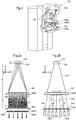
- Fig. 1 illustrates an x-ray imaging system 101 according to one embodiment, based on a photon-counting detector 105 that scans the image field in one direction.
- the system according to this embodiment is based on the existing scanning systems for x-ray imaging developed by the applicant, whereby the system have the same external features as are for instance known from document US 7496,176 .
- the system thus comprises an x-ray source 104 arranged in a housing, patient support and pre-collimator 106a housing and compression paddle 107a, 107b.
- a collimator is arranged in a collimator support, and the patient support comprises a detector 105 comprising a plurality of detector strips 105a.
- the x-ray source 104 and the detector 105 are arranged essentially in respective ends of a scan arm 103, hence arranged to be displaced radially with the x-ray source 104 in the centre.
- An image is acquired by scanning the detector 105 across an image field and applying absorption contrast principles. Whenever the detector 105 has scanned a predefined distance, the number of photon counts collected is read-out and the counter is reset.
- any other type of x-ray system may implement the phase contrast imaging capability described herein, preferably systems with a scan movement to cover and generate an image of an object, by irradiating the object with x-ray beams..
- Fig. 2a disclosing one embodiment of the invention, shows a schematic view of a cross-section of the x-ray imaging system 101 enabling phase contrast imaging, set up in a x-z plane as defined by the coordinate system seen in the figure.
- the system according to this embodiment comprises a Talbot interferometer set up, and is thus based on so-called Talbot interferometry, also known as grating interferometry, grating-based phase contrast imaging, or differential phase contrast imaging, wherein phase shift is inferred by intensity differences, generated by placing a number of gratings in the beam 122 path.
- Talbot interferometry also known as grating interferometry, grating-based phase contrast imaging, or differential phase contrast imaging, wherein phase shift is inferred by intensity differences, generated by placing a number of gratings in the beam 122 path.
- a source grating 160 is arranged slightly displaced from the x-ray source 104 in the direction of the x-ray radiation field towards the detector 105.
- the source grating 160 lines extends in a y-direction.
- the purpose of the source grating 160 is to generate an array of small x-ray sources 104, which improves photon economy substantially compared to a single small x-ray source 104 without reducing coherence.
- a phase grating 161 is arranged with the purpose to introduce an effect known as Talbot self images, which are interference fringes 163 that appear at periodic distances from the grating and parallel with the grating strips, also known as grating lines.
- a pre-collimator 106a may be arranged essentially adjacent the phase grating 161, as seen in this embodiment to further enhance dose efficiency by illuminating only the parts of the object that can be seen with the detector..
- an exemplary triangularly shaped object 108 is arranged between the phase grating 161 and the detector 105 according to this embodiment, however said object 108 but may also be arranged between the x-ray source 104 and the phase grating 161 and achieve similar effects.
- the object 108 corresponds to e.g. a breast in a mammography application.
- an analyzer grating 162 is arranged.
- the analyzer grating lines 162a extends in first direction corresponding to the scan direction y, whereas a plurality of grating slits, i.e.
- openings 162b, of the analyzer grating 162 extends in a second direction x, perpendicular to the scan direction, whereas the analyzer grating 162 extends a longer distance in the first direction than in the second direction.
- the pitch 162d of the analyzer grating 162 is referred to as the distance between the center of two adjacent closures 162c of the grating as can be seen in Fig. 2a , or in other words, as the total length of the width of one opening and one closure 162c in the grating.
- a second post-collimator 106b may be arranged to further reduce photon scattering and thereby improve dose efficiency.
- the phase grating 161 is illuminated by the x-ray source 104 which is covered by a source grating 160 and induces interference fringes 163.
- the fringes 163 are displaced by the phase gradient, i.e. the derivative of the phase shift, in the object, and the fringe period 163d remains constant.
- the fine-pitch 162d analyzer grating 162 arranged in association with the detector 105 can be used to derive the fringe displacement and hence the phase shift.
- L is the source-to-grating distance
- n is the Talbot order
- p 1 is the pitch 162d of the phase grating 161
- ⁇ is the x-ray wavelength
- ⁇ is the parameter that depends on the phase grating 161 type.
- the Talbot images generated from the different source slits coincide and generate a higher flux, which is of relevance to keep down the exposure time in phase-contrast imaging.
- ⁇ ⁇ ' ⁇ /2 ⁇
- ⁇ ' the differential phase shift of the object.
- the fringes 163 are periodic as a function of x, i.e. in the x direction in the set up according to the embodiment.
- a phase gradient in the object 108 causes a phase shift of the fringes 163, which can be measured to obtain ⁇ ' by the intensity variations sensed behind the analyzer gratings 162.
- the phase shift ⁇ may be obtained by integration of ⁇ ' .
- the placing of the analyzer gratings 162 before the detector 105 is not theoretically necessary in order for a detector 105 to sense the fringe displacement; however it reduces the resolution requirement of the detector 105. Detectors 105 with enough resolution to detect ⁇ p f may in fact be difficult and expensive to manufacture.
- Fig. 2b shows a cross-section of the schematic view of the x-ray imaging system 101 set up as seen in Fig. 2a in a y-z plane. From this direction, it is made clear that the set up comprises a multi-slit geometry, according to well-known principles developed by the applicant, wherein the detector 105 comprises a plurality of Si strip detector 105s aligned with each of the plurality of slits of the pre-collimator 106a and post-collimator 106b. According to one embodiment, 21 strip detectors 105 are preferably used in a detector 105. Above and in association to each of a plurality of the detector strips 105a, analyzer gratings 162 have been arranged.
- the analyzer gratings are directed towards the x-ray source to minimize losses caused by the high aspect ratio of the analyzer gratings, i.e. in order to increase the dose efficiency and reduce scatter, the openings of the analyzer gratings are made more aligned with the direction of the x-ray beams.
- such direction may require tilting of the analyzer gratings such that they essentially have their opening perpendicular to the incident x-ray beams, similar to the direction of the surface of each detector strip 105a.
- each analyzer grating 162 comprises several smaller units, adapted to be connected to each other during the manufacturing of the analyzer gratings 162.
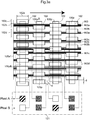
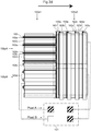
- Fig. 3a shows a portion of the detector 105 comprising four detector strips 105a, the figure essentially viewed in a direction of incident x-ray beams 122 towards the detector 105, essentially in a negative z-direction according to the coordinate system of Fig. 2a and Fig. 2b .
- Four analyzer gratings 162 are arranged in association to these detector strips 105a, i.e. they are arranged in manner along the detector strips 105a in a second direction x to alternately cover and not cover the detector strips 105a with the openings 162b and closures 162cof the analyzer gratings 162.
- each detector strips 105a are built up by a plurality of detector 105 pixels 105p arranged side-by-side in an x-direction as seen in the figure. To facilitate the illustration of the set up, the pixels have been made essentially rectangular. However, they may have any other type of shape.
- the analyzer gratings 162 are arranged directly on the detector strips 105a, for instance by a snap-fit connection between the analyzer gratings and the detector strips, but in another embodiment there is a slight distance between the detector strips 105a and the analyzer gratings 162.
- the analyzer gratings 162 are arranged directly on the post-collimator 106b which in turn is arranged directly on the detector 105.
- the analyzer gratings 162 are arranged slightly displaced relative to each other in systematic manner in an x-direction, perpendicular to the scan direction, wherein the displacement is essentially equal for two consecutive detector strips 105a with analyzer gratings 162.
- the displacement distance d i.e.
- the displacement of grating slits of the analyzer gratings 162 along a plurality of detector strips 105a is defined such that the plurality of detector strips 105a with analyzer gratings 162 samples an entire fringe period 163d of interference fringes 163 generated by a phase grating and displaced by a phase gradient in the object 108 when the object 108 is scanned during the scanning movement in the y-direction.
- no additional scan is required in the x-direction according to e.g. a step-scan approach, since the fringe period 163d in the x-direction is scanned along with the scan movement in the y-z-plane.
- the displacement d is a fraction of the fringe period 163d p f , the fraction varying essentially between 1 and the number of detector strips 105a with analyzer gratings 162, i.e. such that p f N ⁇ d ⁇ p f , where N is the number of detector strips 105a with analyzer gratings 162.
- the displacement d is between, p f 3 ⁇ d ⁇ p f , preferably p f 3 .
- the fringes 163 are represented by the lines in the scan direction y.
- the darkest sections 163a of the lines represent the fringe maxima 163a of the fringe function and the middle of the white sections 163b represents the fringe minima 163b of the function.
- the sections surrounding the fringe maxima 163a thus represent an area of increasing/decreasing intensity 163c of the fringes 163.
- the fringe period 163d is thus defined as the distance between for instance two fringe maxima 163a.
- the fringes 163 of Fig. 3a are equal for each detector strip 105, which thus schematically shows each detector strip 105a scanning the same point in the object 108 at different points in time.
- the period of the analyzer grating 162 is the same as the period of the interference fringes 163 P f , i.e. wherein the width of the grating openings 162b corresponds to the width of the fringes 163, i.e. half the fringe period 163d, comprising the fringe maxima 163a and the section surrounding the fringe maxima 163a.
- the pixels 105p of each detector strip 105a are adapted to sense the intensity of the fringe function and transmit a corresponding signal to a control unit 121.
- such signal may correspond to a sensed fringe maxima 163a as in pixel 105p A in detector strip 105a1, a sensed intensity corresponding anywhere between an intensity maxima and minima as for instance in pixel 105p A and B in detector strip 105a2, or an intensity minima as in for instance in pixel 105p B of detector strip 105a 1, as shown in the squares corresponding to the sensed data by the control unit 121.
- the location of the interference fringes 163 in each pixel is deduced from the detected signals from a number of detector strips at the same point in the object. The displacement of the interference fringes 163 in each pixel can then be calculated by comparing to a reference scan.
- detector strip 105a1 and detector strip 105a2 wherein both signals relating to intensity maxima and intensity minima are detected from pixels 105p in the same detector strips 105a.
- phase contrast signal may be calculated for each pixel 105a.
- the intensity maxima and minima are simply arranged in an image corresponding to the object wherein phase shift occurs, for the operator of the imaging system to interpret and identify interesting areas by the aid of this information.
- the absorption contrast is detected in the scan direction, i.e. by averaging over the number of detector strips 105a required to cover an entire fringe period 163d, wherein the average value of the intensity over the pixels 105p of these detector strips 105a generate the absorption contrast one position of the image.
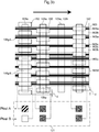
- Fig. 3b shows a portion of the detector 105 similar to that of Fig. 3a , and a systematic displacement of the analyzer gratings 162 of two consecutive detector strips 105a with associated analyzer gratings 162, where at least one detector strip 105a, is arranged between two consecutive detector strips 105a upon which no analyzer grating 162 has been arranged.
- the analyzer gratings 162 does not have to be arranged on every detector strip 105a in the detector 105, i.e. on adjacent detector strips 105a, and the displacement d can thus be measured between two consecutive detector strips 105a upon which an analyzer grating 162 is arranged.
- the order of consecutive detector strips 105a with analyzer gratings 162 may be random. However, the total number of detector strips 105a with analyzer grating 162 must be sufficient to cover an entire fringe period 163d of interference fringes 163. According to one embodiment, wherein the displacement is set to p f 3 , at least three detector strips 105a would be required.
- Fig. 3c shows a portion similar to that of Fig. 3a of the detector 105, but wherein the displacement d between two consecutive detector strips 105a with analyzer gratings 162s, in this case adjacent detector strips 105a, are displaced relative to each other in the second direction in an arbitrary manner, wherein the arbitrary manner comprises a random displacement.
- the only restriction on the randomness of the displacement is that when the summarizing all strips with analyzer gratings 162 they sample an entire fringe period 163d of interference fringes 163 generated by a phase grating and displaced by a phase gradient in the object 108 when the object 108 is scanned. That is, the random displacement needs to be uniformly distributed and range over the entire fringe period.
- phase grating 161 imaging to function for a detector 105 with a random displacement of analyzer gratings 162
- the system needs to be calibrated accordingly such that the exact positioning of the analyzer gratings is known by a processing device (not shown) which generates the data necessary for displaying an image.
- a processing device not shown
- Such calibration may for instance be implemented by the placing of a test object with known phase shift in the x-ray beam.
- any type of placement of analyzer gratings systematic or random, may preferably be calibrated according to this or other methods.
- the random displacement of analyzer gratings 162 may occur on a random or arbitrary order of consecutive detector strips 105a with analyzer gratings 162 as well.
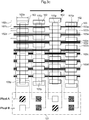
- Fig. 3d shows a portion of the detector 105, wherein only two detector strips are shown.
- Analyzer gratings 162 have been arranged in a crosswise manner over the entire length of the detector strips 105a2 as seen in the figure, such as the grating lines are arranged in the x-direction to cover the entire image field in this direction.
- the grating lines between two detector strips 105a2 with crosswise arranged analyzer gratings 162 are displaced a distance d 2 (not shown) over a plurality of detector strips 105a in the scan direction, such that an entire fringe period 163d in the y-direction is covered by the openings 162b of the crosswise analyzer grating 162ds.
- the displacement d 2 is a fraction of the fringe period 163d P f 2 , in the y-direction similar to the displacement d previously described, wherein the fraction varies essentially between 1 and the number of detector strips 105a2 with crosswise analyzer gratings 162d, i.e. such that P f N ⁇ d ⁇ P f , where N is the number of detector strips 105a with analyzer gratings 162.
- the displacement d is in the range P f 2 3 ⁇ d ⁇ P f 2 , preferably P f 2 3 .
- phase contrast detection is now possible in two dimensions along with the absorption contrast detection, to further enhance the ability to detect risk areas and abnormalities in a scanned object.
- a detector 105 arrangement according to one embodiment of the invention is illustrated for enhancing phase contrast information.
- the photon energy is inversely proportional to the x-ray wave length ( ⁇ ).
- ⁇ and d n thus implicates that there is an optimal energy E 0 for a given distance between a phase grating 161 and the analyzer grating 162.
- the efficiency of the phase contrast detection varies with the energy spectrum of the photons impinging on the detector 105 due to the varying visibility of the fringe function with the energy.
- the energy spectrum varies for instance with the setting of the acceleration voltage of the x-ray source 104 by an operator prior to a scan or gradients in breast thickness.
- variations may also be caused by a so-called automatic exposure control (AEC) when implemented in the system, wherein the x-ray flux is optimized based on the breast thickness, sensed by the detector 105 during the beginning of scan by adaptively changing the x-ray source 104 acceleration voltage.
- AEC automatic exposure control
- An AEC is important when acquiring high quality absorption images and must therefore function parallel to a phase contrast detection functionality.
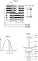
- the detector 105 assembly according to Fig. 4a proposes a detector 105 with energy weighting capabilities to overcome this limitation. According to a simplified arrangement, the pixels 105p of each detector strip 105a in the detector 105 is connected to an amplification block 164a, a comparator block 164b, and a counter block 164c.
- an x-ray source 104 irradiates an object 108 and the detector 105 with an x-ray beam 122.
- the x-ray beam 122 containing photons with a certain energy spectrum is filtered by the object, and phase shifts of the photons may further occur.
- the photons carry relevant information when incident onto the detector 105.
- a signal is created based on the energy of the photon in the detector pixels.
- the pixel 105p signals are readout by first being amplified by an amplifier. After amplification the signal may be altered by a band pass filter or shaper, wherein signal to noise ratio is improved by suppressing high frequencies.
- the amplitude of the signal is compared to threshold levels in a comparator block, whereupon the comparator outputs 1 if the signal is above a threshold, and 0 if the signal is below the threshold.
- a photon pulse counter then increases its number every time the input changes from 0 to 1. With the aid of comparators, it is possible to count each photon having an energy within a certain energy interval.
- Fig. 4b a shows the energy spectrum of incident photons on a detector according to one embodiment of the x-ray imaging apparatus.
- the optimal energy is denoted E 0
- a lower threshold is denoted E 1
- a higher threshold is denoted E 2 .
- the photons having an energy within the energy interval E 1 to E 2 relevant for phase contrast is assigned a higher weight for the phase contrast image effect, by either reading out or by using only photons within this energy interval.
- the setting of the energy interval in the may be adjustable to comply with non-fix systems wherein the distance d n is adjustable.
- the width of the energy interval may also depend on the setting of the x-ray source, wherein a higher acceleration leading to a larger flux or intensity of photons, adjusts he energy interval to be more narrow and closer to the optimal energy E 0 .
- the flux increases, a higher amount of photons with energy close to E 0 will impinge the detector such that the quality of the image may increase. If the flux of photons is low, however, photons within a wider energy interval will have to be included to enhance the image quality.
- the content of the photon pulse counters may be readout to a control unit 121 for optimally weighting the photons, for image processing and presentation.
- the photons having an energy within the energy interval relevant for phase contrast is assigned a higher weight for the phase contrast image effect, wherein the photons having an energy within the energy interval extra relevant for absorption contrast is assigned a higher weight for the absorption contrast image effect.
- the weighting is based on pre set criteria in the control unit, for phase contrast photons may be assigned a 1 if inside the interval, and 0 if outside, and for absorption contrast, the photons having energies within the energy interval of extra importance to absorption contrast, are assigned a value higher than 0 according to one embodiment.
- the setting of the energy intervals may be adjustable to comply with non-fix systems wherein the distance d n is adjustable. This requires a set up of comparators and counters adapted to count photons within two energy intervals, a first energy interval defined by first lower threshold and a second higher threshold, and a second interval defined by a first lower threshold and a second, higher threshold. Assigning a higher weight, may, especially for the case of phase contrast photons comprise weighting by the factor 1.
- three energy levels are used to count and weight photons according to increase phase contrast and absorption contrast effects, essentially dividing the energy spectra into three energy intervals, wherein the upper and lower limits are defined by infinitely high energies and 0 respectively.
- photon with energies within the lower energy interval is filtered out and used for phase contrast.
- Photons with energies within the middle energy interval is counted and/or weighted positive, i.e. assigned a higher weight for absorption contrast and photons within the upper energy interval is counted and assigned a higher weight for phase contrast.
- the weighting of phase contrast photons may include weighting with a factor 1.
- Fig. 5 shows a scan arm 103 with an x-ray source 104 and a detector 105 arranged at two positions, 107a1 and 107a2 respectively, essentially in each end of the scan arm 103.
- a phase grating 161 and pre-collimator 106a is arranged between the x-ray source 104 and the detector 105.
- a compression paddle 107a, 107b is arranged to move and/or compress the object 108 such as a breast in a vertical direction.
- a compression paddle 107a, 107b is used for pressing the breast towards downwards towards a second compression paddle 107a, 107b, also known as the object 108 table.
- the breast needs to be placed as far away from the detector 105.
- the farther away from the detector 105 the larger the fringe displacement detectable by the detector 105.
- the height of the compression paddles 107a, 107b should be adjusted based on and prior to the preferred type of scan to be performed. This could be implemented such that the height is automatically adjusted based on the setting by an operator of the x-ray imaging system 101.
- the present invention should not be limited to extracting phase-contrast information from the detected signals of the interference fringes.
- information about the object scattering ability so-called dark-field imaging, such as in.
Landscapes
- Health & Medical Sciences (AREA)
- Life Sciences & Earth Sciences (AREA)
- Engineering & Computer Science (AREA)
- Medical Informatics (AREA)
- Physics & Mathematics (AREA)
- Pathology (AREA)
- General Health & Medical Sciences (AREA)
- Surgery (AREA)
- Veterinary Medicine (AREA)
- Nuclear Medicine, Radiotherapy & Molecular Imaging (AREA)
- Radiology & Medical Imaging (AREA)
- Biomedical Technology (AREA)
- Heart & Thoracic Surgery (AREA)
- Molecular Biology (AREA)
- High Energy & Nuclear Physics (AREA)
- Animal Behavior & Ethology (AREA)
- Biophysics (AREA)
- Public Health (AREA)
- Optics & Photonics (AREA)
- Chemical & Material Sciences (AREA)
- Dentistry (AREA)
- Oral & Maxillofacial Surgery (AREA)
- Crystallography & Structural Chemistry (AREA)
- Analytical Chemistry (AREA)
- Biochemistry (AREA)
- General Physics & Mathematics (AREA)
- Immunology (AREA)
- Mathematical Physics (AREA)
- Computer Vision & Pattern Recognition (AREA)
- Apparatus For Radiation Diagnosis (AREA)
- Analysing Materials By The Use Of Radiation (AREA)
Description
- The present invention relates generally to an improved x-ray imaging apparatus in the field of mammography, tomosynthesis, radiography, wherein phase contrast imaging capabilities have been implemented.
- In prior art it has been proposed to use phase contrast in x-ray imaging to increase signal-to-noise ratio (SNR) in e.g. mammographic applications. Medical x-ray imaging is often limited by small contrast differences and high noise caused by tight dose restraints. This is particularly true for mammography where low contrast tumors constitute a major detection target, and a large number of tumors are missed or misdiagnosed due to difficulties in detection. The use of phase contrast imaging in medical applications have shown promising in order to increase SNR, since the phase shift in soft tissue is in many cases substantially larger than the absorption.
- International patent application
WO 2008/006470 A1 describes the use of interferometers for x-rays wherein x-ray images can be acquired from a scanned object. The set up herein comprises means for evaluating intensities on apixel 105p basis in order to identify characteristic of theobject 108 by characterizing eachpixel 105p as being for instance phase contrast or absorption contrast dominated. In one application concerning the investigation of luggage on a moving conveyor belt, a set-up comprising an array of line detector 105s and a number of sub-gratings are arranged between theobject 108 and the line detector 105s wherein each of the sub-gratings are shifted in their position perpendicular to the grating lines. In this manner, luggage to be investigated is moved along a direction perpendicular to the grating lines during a scan, wherein one scan movement is required to acquire phase contrast and absorption contrast data. - There are a number of disadvantages with the art presented above. First of all, the solution requires the manufacturing of physically long sub-gratings G1n and G2n, which is consumes resources in terms of cost and time.
- Another drawback is that the proposed set up if directly implemented in a mammography application is likely to induce errors in the phase detection due to the direction of the scan vs the direction of phase contrast detection. When a
stationary object 108 such as a breast is analyzed, the set up needs to be moved in a scan direction in relation to theobject 108 to create an x-ray image of the object, not the other way around as inWO 2008/006470 A1 . An example of a scanning x-ray mammographic imaging system with absorption contrast functionality can be seen in document X, by the applicant. InWO 2008/006470 A1 , the scan direction is set to be perpendicular to the grating lines of the sub-gratings, and hence perpendicular to theinterference fringes 163 to be detected. It is well known that any system, including scanning systems, generally introduce more disturbances in the scan direction since this is the direction of change. Another source of disturbance is the gravity itself on a movingscan arm 103, since a gravity component of thescan arm 103 will induce a torque on adetector 105/analyzer grating 162 relative to thebeam 122 splitter. Hence, a small shift between the analyzer grating 162 and thebeam 122 splitter due to gravitation will further induce errors in the phase detection. In conclusion, in order to reduce these disturbances a set up as in the prior art needs have very high requirements on scan precision, which will make the manufacturing of such products more costly as well as time-consuming. - Yet another drawback of the prior art is that the full potential of using phase contrast, especially sought for in mammographic applications, is not utilized. One of the main advantages of using phase contrast imaging is the reduced noise at high spatial frequencies, i.e. an improved ability to detect small features. In a scanning system, spatial resolution is generally lower in the scan direction since continuous read out is most often implemented.
-
US2010/091936A1 discloses a CT system with a source grating in front of a source, a phase grating, and an analysis grating. The target is placed in-between the phase grating and the analysis grating. A detector grid is placed behind the analysis grating. The previously described elements are configured to rotate around the target. The phase grating and analysis grating may be displaced in the "x" direction). - An object of the present invention is to alleviate some of the disadvantages of the prior art and to provide an improved X-ray imaging system according to claim 1.
- Other embodiments are defined in claims 2 - 17.
- The invention is now described, by way of example, with reference to the accompanying drawings, in which:
-
Fig. 1 shows a perspective view of an x-ray imaging system -
Fig. 2a shows a schematic view of the x-ray imaging system set up in a x-z-plane, corresponding to the phase contrast plane -
Fig 2b shows a schematic view of the x-ray imaging system set up as seen inFig. 2a in a y-z plane, corresponding to the absorption contrast plane -
Fig. 3a shows a portion of the detector and a systematic displacement of the analyzer grating of adjacent detector strips -
Fig. 3b shows portion of the detector and a systematic displacement of the analyzer grating of non adjacent detector strips -
Fig. 3c shows a portion of the detector and a random displacement of theanalyzer gratings 162 of adjacent detector strips -
Fig. 3d shows a portion of the detector and a systematic displacement of the analyzer grating arranged in a perpendicular direction in a cross-wise manner -
Fig. 4a shows the detector and a set up for energy weighting -
Fig. 4b shows energy distribution of photons of an x-ray source -
Fig. 5 shows a compression paddle in two alternative positions. - In the following, a detailed description of the invention will be given.
-
Fig. 1 illustrates anx-ray imaging system 101 according to one embodiment, based on a photon-countingdetector 105 that scans the image field in one direction. The system according to this embodiment is based on the existing scanning systems for x-ray imaging developed by the applicant, whereby the system have the same external features as are for instance known from documentUS 7496,176 . The system thus comprises anx-ray source 104 arranged in a housing, patient support and pre-collimator 106a housing andcompression paddle detector 105 comprising a plurality ofdetector strips 105a. Thex-ray source 104 and thedetector 105 are arranged essentially in respective ends of ascan arm 103, hence arranged to be displaced radially with thex-ray source 104 in the centre. An image is acquired by scanning thedetector 105 across an image field and applying absorption contrast principles. Whenever thedetector 105 has scanned a predefined distance, the number of photon counts collected is read-out and the counter is reset. However any other type of x-ray system may implement the phase contrast imaging capability described herein, preferably systems with a scan movement to cover and generate an image of an object, by irradiating the object with x-ray beams.. -
Fig. 2a , disclosing one embodiment of the invention, shows a schematic view of a cross-section of thex-ray imaging system 101 enabling phase contrast imaging, set up in a x-z plane as defined by the coordinate system seen in the figure. The system according to this embodiment comprises a Talbot interferometer set up, and is thus based on so-called Talbot interferometry, also known as grating interferometry, grating-based phase contrast imaging, or differential phase contrast imaging, wherein phase shift is inferred by intensity differences, generated by placing a number of gratings in thebeam 122 path. The scan direction along a radial path, with thex-ray source 104 in the center as seen inFig. 1 , is defined to be in the y-z plane, denoted by the arrow inFig. 2b . InFig. 2a thex-ray source 104 is arranged at the uppermost position of the system radiating thedetector 105 arranged at the lowermost position in the figure. Thex-ray source 104 emits anx-ray radiation beam 122. In one embodiment, a source grating 160 is arranged slightly displaced from thex-ray source 104 in the direction of the x-ray radiation field towards thedetector 105. The source grating 160 lines extends in a y-direction. The purpose of the source grating 160 is to generate an array ofsmall x-ray sources 104, which improves photon economy substantially compared to a singlesmall x-ray source 104 without reducing coherence. Further down in the direction of the x-ray radiation field, a phase grating 161, sometimes denotedbeam 122 splitter, is arranged with the purpose to introduce an effect known as Talbot self images, which areinterference fringes 163 that appear at periodic distances from the grating and parallel with the grating strips, also known as grating lines. A pre-collimator 106a may be arranged essentially adjacent the phase grating 161, as seen in this embodiment to further enhance dose efficiency by illuminating only the parts of the object that can be seen with the detector.. To facilitate the understanding of the workings of the phase contrast effect, an exemplary triangularly shapedobject 108 is arranged between the phase grating 161 and thedetector 105 according to this embodiment, however saidobject 108 but may also be arranged between thex-ray source 104 and the phase grating 161 and achieve similar effects. Theobject 108 corresponds to e.g. a breast in a mammography application. Slightly above thedetector 105 as seen in a direction towards the phase grating 161, ananalyzer grating 162 is arranged. Theanalyzer grating lines 162a extends in first direction corresponding to the scan direction y, whereas a plurality of grating slits, i.e.openings 162b, of the analyzer grating 162 extends in a second direction x, perpendicular to the scan direction, whereas the analyzer grating 162 extends a longer distance in the first direction than in the second direction. Thepitch 162d of the analyzer grating 162 is referred to as the distance between the center of twoadjacent closures 162c of the grating as can be seen inFig. 2a , or in other words, as the total length of the width of one opening and oneclosure 162c in the grating. Between the analyzer grating 162 and thedetector 105 a second post-collimator 106b may be arranged to further reduce photon scattering and thereby improve dose efficiency. Thus, as seen in the figure, the phase grating 161 is illuminated by thex-ray source 104 which is covered by a source grating 160 and inducesinterference fringes 163. Thefringes 163 are displaced by the phase gradient, i.e. the derivative of the phase shift, in the object, and thefringe period 163d remains constant. The fine-pitch 162d analyzer grating 162 arranged in association with thedetector 105 can be used to derive the fringe displacement and hence the phase shift. - For a
spherical beam 122 induced by a point source, the so-called Talbot distances are:
- Here, L is the source-to-grating distance, n is the Talbot order, p1 is the
pitch 162d of the phase grating 161, λ is the x-ray wavelength, and η is the parameter that depends on the phase grating 161 type. - Assuming a π phase-shifting phase grating 161 according to one embodiment, which implies η = 2. For a π/2-shifting phase grating 161, η = 1.
- The period of the
interference fringes 163 is
- Again, Pf = pf (L → ∞) is the
fringe period 163d for a plane incident wave. If the source is covered with a source grating 160 withopenings 162b that are s wide and with apitch 162d of
- The Talbot images generated from the different source slits coincide and generate a higher flux, which is of relevance to keep down the exposure time in phase-contrast imaging.
- When a
phase shifting object 108 is introduced in thebeam 122, it is refracted an angle α =Φ'λ/2π, where Φ' is the differential phase shift of the object. For small a, the refraction causes a fringe displacement
detector 105 to 1 for anobject 108 at or upstream of the phase grating 161. Thefringes 163 are periodic as a function of x, i.e. in the x direction in the set up according to the embodiment. Thus, a phase gradient in theobject 108 causes a phase shift of thefringes 163, which can be measured to obtain Φ' by the intensity variations sensed behind theanalyzer gratings 162. The phase shift Φ may be obtained by integration of Φ'. The placing of theanalyzer gratings 162 before thedetector 105 is not theoretically necessary in order for adetector 105 to sense the fringe displacement; however it reduces the resolution requirement of thedetector 105.Detectors 105 with enough resolution to detect Δpf may in fact be difficult and expensive to manufacture. One method used in the past comprising the analyzer grating 162 is the step-wise movement of the analyzer grating 162 in the x-direction until theentire fringe period 163d is covered by theopenings 162b of the analyzer grating 162, preferably in at least M=3 measurements or steps. Such methods are normally referred to as phase stepping methods. -
Fig. 2b shows a cross-section of the schematic view of thex-ray imaging system 101 set up as seen inFig. 2a in a y-z plane. From this direction, it is made clear that the set up comprises a multi-slit geometry, according to well-known principles developed by the applicant, wherein thedetector 105 comprises a plurality of Si strip detector 105s aligned with each of the plurality of slits of the pre-collimator 106a and post-collimator 106b. According to one embodiment, 21strip detectors 105 are preferably used in adetector 105. Above and in association to each of a plurality of the detector strips 105a,analyzer gratings 162 have been arranged. As stated earlier, a scanning movement takes place in the y-z plane, essentially in the y-direction, as is also shown by the arrows in the figure. This direction is thus adapted to measure absorption contrast of an object, which will be further described below. According to one embodiment, the analyzer gratings are directed towards the x-ray source to minimize losses caused by the high aspect ratio of the analyzer gratings, i.e. in order to increase the dose efficiency and reduce scatter, the openings of the analyzer gratings are made more aligned with the direction of the x-ray beams. According to one embodiment, such direction may require tilting of the analyzer gratings such that they essentially have their opening perpendicular to the incident x-ray beams, similar to the direction of the surface of eachdetector strip 105a. - According to one embodiment, each analyzer grating 162 comprises several smaller units, adapted to be connected to each other during the manufacturing of the
analyzer gratings 162. -
Fig. 3a shows a portion of thedetector 105 comprising fourdetector strips 105a, the figure essentially viewed in a direction of incident x-ray beams 122 towards thedetector 105, essentially in a negative z-direction according to the coordinate system ofFig. 2a and Fig. 2b . Fouranalyzer gratings 162 are arranged in association to thesedetector strips 105a, i.e. they are arranged in manner along thedetector strips 105a in a second direction x to alternately cover and not cover thedetector strips 105a with theopenings 162b and closures 162cof theanalyzer gratings 162. Further, eachdetector strips 105a are built up by a plurality ofdetector 105pixels 105p arranged side-by-side in an x-direction as seen in the figure. To facilitate the illustration of the set up, the pixels have been made essentially rectangular. However, they may have any other type of shape. In one embodiment theanalyzer gratings 162 are arranged directly on thedetector strips 105a, for instance by a snap-fit connection between the analyzer gratings and the detector strips, but in another embodiment there is a slight distance between thedetector strips 105a and theanalyzer gratings 162. In yet another embodiment, theanalyzer gratings 162 are arranged directly on the post-collimator 106b which in turn is arranged directly on thedetector 105. According to the embodiment ofFig. 3a , theanalyzer gratings 162 are arranged slightly displaced relative to each other in systematic manner in an x-direction, perpendicular to the scan direction, wherein the displacement is essentially equal for twoconsecutive detector strips 105a withanalyzer gratings 162. The displacement distance d, i.e. the displacement of grating slits of theanalyzer gratings 162 along a plurality ofdetector strips 105a is defined such that the plurality ofdetector strips 105a withanalyzer gratings 162 samples anentire fringe period 163d ofinterference fringes 163 generated by a phase grating and displaced by a phase gradient in theobject 108 when theobject 108 is scanned during the scanning movement in the y-direction. In this manner, no additional scan is required in the x-direction according to e.g. a step-scan approach, since thefringe period 163d in the x-direction is scanned along with the scan movement in the y-z-plane. - The displacement d is a fraction of the
fringe period 163d pf , the fraction varying essentially between 1 and the number ofdetector strips 105a withanalyzer gratings 162, i.e. such that
detector strips 105a withanalyzer gratings 162. According to one preferred embodiment, the displacement d is between,

- In
Fig. 3a thefringes 163 are represented by the lines in the scan direction y. Thedarkest sections 163a of the lines represent thefringe maxima 163a of the fringe function and the middle of thewhite sections 163b represents thefringe minima 163b of the function. The sections surrounding thefringe maxima 163a thus represent an area of increasing/decreasingintensity 163c of thefringes 163. Hence, thefringe period 163d is thus defined as the distance between for instance twofringe maxima 163a. Thefringes 163 ofFig. 3a are equal for eachdetector strip 105, which thus schematically shows eachdetector strip 105a scanning the same point in theobject 108 at different points in time. In reality it is namely unlikely that theobject 108 would be phase-homogenous over an area in anobject 108 corresponding to fourdetector strips 105a during a scan. Rather, the fringe pattern will vary between eachdetector strip 105. According to one embodiment, the period of the analyzer grating 162 is the same as the period of the interference fringes 163 Pf, i.e. wherein the width of thegrating openings 162b corresponds to the width of thefringes 163, i.e. half thefringe period 163d, comprising thefringe maxima 163a and the section surrounding thefringe maxima 163a. Thepixels 105p of eachdetector strip 105a are adapted to sense the intensity of the fringe function and transmit a corresponding signal to acontrol unit 121. In the figure, such signal may correspond to a sensedfringe maxima 163a as inpixel 105p A in detector strip 105a1, a sensed intensity corresponding anywhere between an intensity maxima and minima as for instance inpixel 105p A and B in detector strip 105a2, or an intensity minima as in for instance inpixel 105p B ofdetector strip 105a 1, as shown in the squares corresponding to the sensed data by thecontrol unit 121. The location of theinterference fringes 163 in each pixel is deduced from the detected signals from a number of detector strips at the same point in the object. The displacement of theinterference fringes 163 in each pixel can then be calculated by comparing to a reference scan. An example of wherein how this can be illustrated is seen in for instance detector strip 105a1 and detector strip 105a2, wherein both signals relating to intensity maxima and intensity minima are detected frompixels 105p in thesame detector strips 105a. Given theconstant fringe period 163d along eachdetector pixel 105p, the only explanation can be that there is a difference in phase shift between the two pixels.. The differential phase shift Φ' in the object can be calculated according to Δpf ≈ Λdn × α =
pixel 105a. - According to another embodiment, the intensity maxima and minima are simply arranged in an image corresponding to the object wherein phase shift occurs, for the operator of the imaging system to interpret and identify interesting areas by the aid of this information. The absorption contrast is detected in the scan direction, i.e. by averaging over the number of
detector strips 105a required to cover anentire fringe period 163d, wherein the average value of the intensity over thepixels 105p of thesedetector strips 105a generate the absorption contrast one position of the image. -
Fig. 3b shows a portion of thedetector 105 similar to that ofFig. 3a , and a systematic displacement of theanalyzer gratings 162 of twoconsecutive detector strips 105a with associatedanalyzer gratings 162, where at least onedetector strip 105a, is arranged between twoconsecutive detector strips 105a upon which no analyzer grating 162 has been arranged. Hence, theanalyzer gratings 162 does not have to be arranged on everydetector strip 105a in thedetector 105, i.e. onadjacent detector strips 105a, and the displacement d can thus be measured between twoconsecutive detector strips 105a upon which ananalyzer grating 162 is arranged. Further, the order ofconsecutive detector strips 105a withanalyzer gratings 162 may be random. However, the total number ofdetector strips 105a with analyzer grating 162 must be sufficient to cover anentire fringe period 163d ofinterference fringes 163. According to one embodiment, wherein the displacement is set to
detector strips 105a would be required. -
Fig. 3c shows a portion similar to that ofFig. 3a of thedetector 105, but wherein the displacement d between twoconsecutive detector strips 105a with analyzer gratings 162s, in this caseadjacent detector strips 105a, are displaced relative to each other in the second direction in an arbitrary manner, wherein the arbitrary manner comprises a random displacement. The only restriction on the randomness of the displacement is that when the summarizing all strips withanalyzer gratings 162 they sample anentire fringe period 163d ofinterference fringes 163 generated by a phase grating and displaced by a phase gradient in theobject 108 when theobject 108 is scanned. That is, the random displacement needs to be uniformly distributed and range over the entire fringe period. In order for phase grating 161 imaging to function for adetector 105 with a random displacement ofanalyzer gratings 162, the system needs to be calibrated accordingly such that the exact positioning of the analyzer gratings is known by a processing device (not shown) which generates the data necessary for displaying an image. Such calibration may for instance be implemented by the placing of a test object with known phase shift in the x-ray beam. According to one embodiment, any type of placement of analyzer gratings, systematic or random, may preferably be calibrated according to this or other methods. In a similar manner to that ofFig 3b , the random displacement ofanalyzer gratings 162 may occur on a random or arbitrary order ofconsecutive detector strips 105a withanalyzer gratings 162 as well. -
Fig. 3d shows a portion of thedetector 105, wherein only two detector strips are shown.Analyzer gratings 162 have been arranged in a crosswise manner over the entire length of the detector strips 105a2 as seen in the figure, such as the grating lines are arranged in the x-direction to cover the entire image field in this direction. The grating lines between two detector strips 105a2 with crosswise arrangedanalyzer gratings 162 are displaced a distance d2 (not shown) over a plurality ofdetector strips 105a in the scan direction, such that anentire fringe period 163d in the y-direction is covered by theopenings 162b of the crosswise analyzer grating 162ds. Preferably, the displacement d2 is a fraction of thefringe period 163d P f2, in the y-direction similar to the displacement d previously described, wherein the fraction varies essentially between 1 and the number of detector strips 105a2 withcrosswise analyzer gratings 162d, i.e. such that
detector strips 105a withanalyzer gratings 162. According to one preferred embodiment, the displacement d is in the range

interference fringes 163 in a y-direction for a detector strip with analyzer gratings in this direction, a corresponding second phase grating 161 needs to be arranged with grating lines in a y-direction. Hence, the direction of the phase grating(s) need to vary with respect to the direction of the analyzer gratings. According to one embodiment, such second phase grating 161 may be arranged in the proximity to the phase grating 161 as previously described, in a crosswise manner together with a first phase grating wherein a cross pattern of interference fringes are generated (not shown). Thus, by the aid of this set up, in one single scan, phase contrast detection is now possible in two dimensions along with the absorption contrast detection, to further enhance the ability to detect risk areas and abnormalities in a scanned object. - In
Fig. 4a adetector 105 arrangement according to one embodiment of the invention is illustrated for enhancing phase contrast information. As has previously been described, the so-called Talbot distances can be described as:
- The photon energy is inversely proportional to the x-ray wave length (λ). The relationship between λ and dn thus implicates that there is an optimal energy E0 for a given distance between a phase grating 161 and the
analyzer grating 162. In a fix system according to one alternative embodiment of the invention, wherein the relative distance between the phase grating 161 and theanalyzer gratings 162 is not adjustable, the efficiency of the phase contrast detection varies with the energy spectrum of the photons impinging on thedetector 105 due to the varying visibility of the fringe function with the energy. The energy spectrum varies for instance with the setting of the acceleration voltage of thex-ray source 104 by an operator prior to a scan or gradients in breast thickness. Further, variations may also be caused by a so-called automatic exposure control (AEC) when implemented in the system, wherein the x-ray flux is optimized based on the breast thickness, sensed by thedetector 105 during the beginning of scan by adaptively changing thex-ray source 104 acceleration voltage. An AEC is important when acquiring high quality absorption images and must therefore function parallel to a phase contrast detection functionality. Thedetector 105 assembly according toFig. 4a proposes adetector 105 with energy weighting capabilities to overcome this limitation. According to a simplified arrangement, thepixels 105p of eachdetector strip 105a in thedetector 105 is connected to anamplification block 164a, acomparator block 164b, and acounter block 164c. As anx-ray source 104 irradiates anobject 108 and thedetector 105 with anx-ray beam 122. Thex-ray beam 122, containing photons with a certain energy spectrum is filtered by the object, and phase shifts of the photons may further occur. Thus, the photons carry relevant information when incident onto thedetector 105. A signal is created based on the energy of the photon in the detector pixels. Thepixel 105p signals are readout by first being amplified by an amplifier. After amplification the signal may be altered by a band pass filter or shaper, wherein signal to noise ratio is improved by suppressing high frequencies. After being amplified, the amplitude of the signal is compared to threshold levels in a comparator block, whereupon the comparator outputs 1 if the signal is above a threshold, and 0 if the signal is below the threshold. A photon pulse counter then increases its number every time the input changes from 0 to 1. With the aid of comparators, it is possible to count each photon having an energy within a certain energy interval. - In
Fig. 4b a shows the energy spectrum of incident photons on a detector according to one embodiment of the x-ray imaging apparatus. The optimal energy is denoted E0 a lower threshold is denoted E1, a higher threshold is denoted E2. Preferably, the photons having an energy within the energy interval E1 to E2 relevant for phase contrast is assigned a higher weight for the phase contrast image effect, by either reading out or by using only photons within this energy interval. The setting of the energy interval in the may be adjustable to comply with non-fix systems wherein the distance dn is adjustable. However, the width of the energy interval may also depend on the setting of the x-ray source, wherein a higher acceleration leading to a larger flux or intensity of photons, adjusts he energy interval to be more narrow and closer to the optimal energy E0. Hence, as the flux increases, a higher amount of photons with energy close to E0 will impinge the detector such that the quality of the image may increase. If the flux of photons is low, however, photons within a wider energy interval will have to be included to enhance the image quality. - According to another embodiment, the content of the photon pulse counters may be readout to a
control unit 121 for optimally weighting the photons, for image processing and presentation. Preferably, the photons having an energy within the energy interval relevant for phase contrast is assigned a higher weight for the phase contrast image effect, wherein the photons having an energy within the energy interval extra relevant for absorption contrast is assigned a higher weight for the absorption contrast image effect. The weighting is based on pre set criteria in the control unit, for phase contrast photons may be assigned a 1 if inside the interval, and 0 if outside, and for absorption contrast, the photons having energies within the energy interval of extra importance to absorption contrast, are assigned a value higher than 0 according to one embodiment. The setting of the energy intervals may be adjustable to comply with non-fix systems wherein the distance dn is adjustable. This requires a set up of comparators and counters adapted to count photons within two energy intervals, a first energy interval defined by first lower threshold and a second higher threshold, and a second interval defined by a first lower threshold and a second, higher threshold. Assigning a higher weight, may, especially for the case of phase contrast photons comprise weighting by the factor 1. - According to another embodiment, three energy levels are used to count and weight photons according to increase phase contrast and absorption contrast effects, essentially dividing the energy spectra into three energy intervals, wherein the upper and lower limits are defined by infinitely high energies and 0 respectively. Preferably, photon with energies within the lower energy interval is filtered out and used for phase contrast. Photons with energies within the middle energy interval is counted and/or weighted positive, i.e. assigned a higher weight for absorption contrast and photons within the upper energy interval is counted and assigned a higher weight for phase contrast. The weighting of phase contrast photons may include weighting with a factor 1.
-
Fig. 5 shows ascan arm 103 with anx-ray source 104 and adetector 105 arranged at two positions, 107a1 and 107a2 respectively, essentially in each end of thescan arm 103. As known from previous figures, e.g.Fig. 2a , a phase grating 161 and pre-collimator 106a is arranged between thex-ray source 104 and thedetector 105. Further, between thex-ray source 104 and thedetector 105 acompression paddle object 108 such as a breast in a vertical direction. In imaging arrangements to the present date, acompression paddle second compression paddle object 108 table. However, in order to increase the effect of the phase contrast in the x-ray image, the breast needs to be placed as far away from thedetector 105. As described, For small a, the refraction causes a fringe displacement
object 108 placed in contact with thedetector 105 to 1 for anobject 108 at or upstream of the phase grating 161. Thus, the farther away from thedetector 105, the larger the fringe displacement detectable by thedetector 105. There is a trade-off between the absorption effect and the phase contrast effect depending on the vertical distance of the scannedobject 108 from theanalyzer grating 162. An increased distance from thedetector 105 will diminish the absorption contrast effect due to scattering effects wherein valuable radiation that has passed theobject 108 is lost. Therefore, the height of thecompression paddles x-ray imaging system 101. - In the field of mammography, there is an increasing demand for three-dimensional (3D) information which can reduce distraction by anatomical structures and provide 3D localization. The proposed embodiments disclosed in this application could readily be implemented in known tomosynthesis solutions, wherein projection angles are generated with the purpose to create projection images when the
x-ray source 104 irradiates each point in anobject 108 from various angles. - The present invention should not be limited to extracting phase-contrast information from the detected signals of the interference fringes. One example of other information that may be available is information about the object scattering ability, so-called dark-field imaging, such as in. In dark-field imaging, the visibility of the detected periodic function, defined as

Claims (17)
- An x-ray imaging system (101) comprising:an x-ray source (104);an x-ray detector (105) comprising a plurality of detector strips (105a) arranged in a first direction of the x-ray detector (105), each detector strip (105a) further comprising a plurality of detector (105) pixels (105p) arranged in a second direction of the x-ray detector (105);a phase grating (161); anda plurality of analyzer gratings (162) comprising grating slits;wherein the x-ray source (104) and the x-ray detector (105) are adapted to perform a scanning movement in relation to an object (108) in the first direction, in order to scan the object;wherein the analyzer gratings (162) are arranged between the x-ray source (104) and the x-ray detector (105), wherein each of the plurality of analyzer gratings (162) is arranged in association with a respective detector strip (105a) with the grating slits arranged in the second direction;and wherein the grating slits of the analyzer gratings (162) of the detector strips (105a) are displaced relative to each other in the second direction;wherein the grating slits of analyzer gratings (162) of two consecutive detector strips (105a) with analyzer gratings (162) in a first direction are displaced relative to each other in the second direction in a systematic manner, wherein the systematic manner comprises a defined displacement distance (d).
- An x-ray imaging system (101) according to claim 1, characterized in that the displacement of grating slits of the analyzer gratings (162) along a plurality of detector strips (105a) samples an entire fringe period (163d) of interference fringes (163) generated by a phase grating and displaced by a phase gradient in the object (108) when the object (108) is scanned.
- An x-ray imaging system (101) according to any one of the claims 1 to 2, characterized in that the displacement distance (d) is a fraction of the fringe period pf , such that

- An x-ray imaging system (101) according to any one of the claims 1 to 3, characterized in that the displacement distance (d) is between,


- An x-ray imaging system (101) according to any of claims 1-4, characterized in that the grating slits of analyzer gratings (162) of two consecutive detector strips (105a) are displaced relative to each other in the second direction in an arbitrary manner, wherein the arbitrary manner comprises a random displacement.
- An x-ray imaging system (101) according to any of claims 1-5, characterized in that two consecutive detector strips (105a) with analyzer gratings (162) in a first direction are two adjacent detector strips (105a).
- An x-ray imaging system (101) according to any of claims 1-6, characterized in that two consecutive detector strips (105a) with analyzer gratings (162) in a first direction are randomly or arbitrarily displaced among the detector strips (105a) in a first direction.
- An x-ray imaging system (101) according to any of claims 1-7, characterized in that the system further comprises a pre-collimator (106a) and a post-collimator (106b), wherein the pre-collimator (106a) is arranged between the analyzer grating (162) and the phase grating (161) and the post-collimator (106b) is arranged between the analyzer grating (162) and the x-ray detector (105).
- An x-ray imaging system (101) according to any of claims 1-8, characterized in that the system further comprises a source grating (160) arranged between the x-ray source (104) and the phase grating (161).
- An x-ray imaging system (101) according to any of claims 1-9, characterized in that that the detector (105) is adapted to count photons impinging on the detector strips (105a) and generate a signal corresponding to the energy of impinging photons, and wherein a control unit (121) is adapted to receive said signals and assign a weight to the phase-contrast image effect in relation to the efficiency at each energy and/or wherein the control unit (121) is adapted to assign a weight to the phase-contrast image effect in relation to the efficiency at each energy.
- An x-ray imaging system (101) according to any of claims 1-10, characterized in that at least one analyzer grating (162) is arranged in a first crosswise direction over the entire detector (105).
- An x-ray imaging system (101) according to any of claims 1-11, characterized in that the system further comprises at least one movable compression paddle (107a, 107b), wherein the compression paddle is adapted to move an object (108), such as a breast, further away from the analyzer grating (162) to increase the phase contrast image effect.
- An x-ray imaging system (101) according to claim 12, characterized in that the compression paddle (107a, 107b) is adapted to move the object (108) within a range between the analyzer grating (162) and the pre-collimator (106a) or the phase grating (161).
- An x-ray imaging system (101) according to claims 1-13, characterized in that the phase grating (161) is arranged on a scan arm (103) in order to follow the scan arm (103) during the scanning movement in relation to the object (108) in the first direction, and/or the phase grating (161) is arranged to be stationary when the scan arm (103), during the scanning movement, is moved in relation to the object (108) and the phase grating (161) in the first direction.
- An x-ray imaging system (101) according to any of claims 1-14, characterized in that the analyzer grating (162) is connected to each of the plurality of detector strips (105a) by a snap-fit like connection.
- An x-ray imaging system (101) according to any of claims 1-15, characterized in that the analyzer gratings (162) are arranged directed towards the x-ray source (104), wherein the tilting direction of the analyzer gratings (162) are essentially equal to the tilting angle (s) of the plurality of detector strips (105a) in relation to the x-ray source (104).
- An x-ray imaging system (101) according to any of the previous claims, characterized in that each analyzer grating (162) comprises several smaller units, adapted to be connected to each other during the manufacturing of the analyzer gratings (162).
Applications Claiming Priority (3)
| Application Number | Priority Date | Filing Date | Title |
|---|---|---|---|
| US201161504260P | 2011-07-04 | 2011-07-04 | |
| SE1150622 | 2011-07-04 | ||
| PCT/EP2012/062489 WO2013004574A1 (en) | 2011-07-04 | 2012-06-27 | Phase contrast imaging apparatus |
Publications (2)
| Publication Number | Publication Date |
|---|---|
| EP2729069A1 EP2729069A1 (en) | 2014-05-14 |
| EP2729069B1 true EP2729069B1 (en) | 2019-09-18 |
Family
ID=47436543
Family Applications (1)
| Application Number | Title | Priority Date | Filing Date |
|---|---|---|---|
| EP12731408.6A Active EP2729069B1 (en) | 2011-07-04 | 2012-06-27 | Phase contrast imaging apparatus |
Country Status (6)
| Country | Link |
|---|---|
| US (1) | US9757082B2 (en) |
| EP (1) | EP2729069B1 (en) |
| JP (1) | JP6353361B2 (en) |
| CN (1) | CN103648388B (en) |
| RU (1) | RU2620892C2 (en) |
| WO (1) | WO2013004574A1 (en) |
Families Citing this family (53)
| Publication number | Priority date | Publication date | Assignee | Title |
|---|---|---|---|---|
| US20150117599A1 (en) | 2013-10-31 | 2015-04-30 | Sigray, Inc. | X-ray interferometric imaging system |
| CN104066375B (en) | 2012-01-24 | 2017-08-11 | 皇家飞利浦有限公司 | Multi-direction phase contrast x-ray imaging |
| JP6173457B2 (en) | 2012-08-20 | 2017-08-02 | コーニンクレッカ フィリップス エヌ ヴェKoninklijke Philips N.V. | Alignment of source grating versus phase grating distance for multi-order phase adjustment in differential phase contrast imaging |
| US9971078B2 (en) * | 2013-03-05 | 2018-05-15 | Rambus Inc. | Phase gratings with odd symmetry for high-resolution lensless optical sensing |
| WO2014187885A1 (en) * | 2013-05-22 | 2014-11-27 | Siemens Aktiengesellschaft | Phase-contrast x-ray imaging device |
| WO2014207193A1 (en) | 2013-06-28 | 2014-12-31 | Koninklijke Philips N.V. | Correction in slit-scanning phase contrast imaging |
| US9297772B2 (en) | 2013-07-30 | 2016-03-29 | Industrial Technology Research Institute | Apparatus for amplifying intensity during transmission small angle—X-ray scattering measurements |
| US10269528B2 (en) | 2013-09-19 | 2019-04-23 | Sigray, Inc. | Diverging X-ray sources using linear accumulation |
| US10295485B2 (en) | 2013-12-05 | 2019-05-21 | Sigray, Inc. | X-ray transmission spectrometer system |
| US10297359B2 (en) | 2013-09-19 | 2019-05-21 | Sigray, Inc. | X-ray illumination system with multiple target microstructures |
| CN104837409B (en) * | 2013-09-30 | 2019-08-13 | 皇家飞利浦有限公司 | Differential Phase Contrast Imaging Device with Movable Grating |
| US10045749B2 (en) | 2013-10-22 | 2018-08-14 | Koninklijke Philips N.V. | X-ray system, in particular a tomosynthesis system and a method for acquiring an image of an object |
| US10304580B2 (en) | 2013-10-31 | 2019-05-28 | Sigray, Inc. | Talbot X-ray microscope |
| USRE48612E1 (en) | 2013-10-31 | 2021-06-29 | Sigray, Inc. | X-ray interferometric imaging system |
| WO2015090949A1 (en) * | 2013-12-17 | 2015-06-25 | Koninklijke Philips N.V. | Phase retrieval for scanning differential phase contrast systems |
| US10401309B2 (en) | 2014-05-15 | 2019-09-03 | Sigray, Inc. | X-ray techniques using structured illumination |
| TWI629474B (en) | 2014-05-23 | 2018-07-11 | 財團法人工業技術研究院 | X-ray source and phase contrast x-ray imaging method |
| JP6369206B2 (en) * | 2014-08-06 | 2018-08-08 | コニカミノルタ株式会社 | X-ray imaging system and image processing apparatus |
| BR112017010593B1 (en) | 2014-11-24 | 2022-11-08 | Koninklijke Philips N.V. | ARRANGEMENT OF X-RAY DETECTOR, IMAGING SYSTEM, METHOD FOR TOMOSYNTHESIS IMAGING WITH X-RAY PHASE CONTRAST AND NON-TRAINER COMPUTER READABLE MEDIA |
| US10352880B2 (en) | 2015-04-29 | 2019-07-16 | Sigray, Inc. | Method and apparatus for x-ray microscopy |
| US10295486B2 (en) | 2015-08-18 | 2019-05-21 | Sigray, Inc. | Detector for X-rays with high spatial and high spectral resolution |
| CN106483548B (en) * | 2015-08-28 | 2019-07-26 | 北京纳米维景科技有限公司 | A kind of photon counting detector array and its imaging method |
| JP6816144B2 (en) * | 2015-12-01 | 2021-01-20 | コーニンクレッカ フィリップス エヌ ヴェKoninklijke Philips N.V. | A device for X-ray imaging of a subject |
| JP6613988B2 (en) * | 2016-03-30 | 2019-12-04 | コニカミノルタ株式会社 | Radiography system |
| US10247683B2 (en) | 2016-12-03 | 2019-04-02 | Sigray, Inc. | Material measurement techniques using multiple X-ray micro-beams |
| WO2018175570A1 (en) | 2017-03-22 | 2018-09-27 | Sigray, Inc. | Method of performing x-ray spectroscopy and x-ray absorption spectrometer system |
| EP3444826A1 (en) * | 2017-08-14 | 2019-02-20 | Koninklijke Philips N.V. | Low profile anti scatter and anti charge sharing grid for photon counting computed tomography |
| EP3447538A1 (en) * | 2017-08-23 | 2019-02-27 | Koninklijke Philips N.V. | X-ray detection |
| EP3446630A1 (en) * | 2017-08-23 | 2019-02-27 | Koninklijke Philips N.V. | Device and method for phase stepping in phase contrast image acquisition |
| US10578566B2 (en) | 2018-04-03 | 2020-03-03 | Sigray, Inc. | X-ray emission spectrometer system |
| CN112424591B (en) | 2018-06-04 | 2024-05-24 | 斯格瑞公司 | Wavelength dispersive X-ray spectrometer |
| DE112019003777B4 (en) | 2018-07-26 | 2025-09-11 | Sigray, Inc. | HIGH BRIGHTNESS X-RAY REFLECTION SOURCE |
| US10656105B2 (en) | 2018-08-06 | 2020-05-19 | Sigray, Inc. | Talbot-lau x-ray source and interferometric system |
| CN112638261B (en) | 2018-09-04 | 2025-06-27 | 斯格瑞公司 | Systems and methods utilizing filtered x-ray fluorescence |
| US11056308B2 (en) | 2018-09-07 | 2021-07-06 | Sigray, Inc. | System and method for depth-selectable x-ray analysis |
| WO2020106197A1 (en) | 2018-11-19 | 2020-05-28 | Prismatic Sensors Ab | X-ray imaging system for phase contrast imaging using photon-counting events |
| JP7182749B2 (en) | 2019-09-03 | 2022-12-02 | シグレイ、インコーポレイテッド | System and method for computed tomography fluorescence X-ray imaging |
| US11175243B1 (en) | 2020-02-06 | 2021-11-16 | Sigray, Inc. | X-ray dark-field in-line inspection for semiconductor samples |
| WO2021168724A1 (en) | 2020-02-27 | 2021-09-02 | Shenzhen Xpectvision Technology Co., Ltd. | Method of phase contrast imaging |
| WO2021237237A1 (en) | 2020-05-18 | 2021-11-25 | Sigray, Inc. | System and method for x-ray absorption spectroscopy using a crystal analyzer and a plurality of detector elements |
| WO2022061347A1 (en) | 2020-09-17 | 2022-03-24 | Sigray, Inc. | System and method using x-rays for depth-resolving metrology and analysis |
| KR20260030946A (en) | 2020-12-07 | 2026-03-06 | 시그레이, 아이엔씨. | High throughput 3d x-ray imaging system using a transmission x-ray source |
| US12480892B2 (en) | 2020-12-07 | 2025-11-25 | Sigray, Inc. | High throughput 3D x-ray imaging system using a transmission x-ray source |
| WO2023168204A1 (en) | 2022-03-02 | 2023-09-07 | Sigray, Inc. | X-ray fluorescence system and x-ray source with electrically insulative target material |
| US11992350B2 (en) | 2022-03-15 | 2024-05-28 | Sigray, Inc. | System and method for compact laminography utilizing microfocus transmission x-ray source and variable magnification x-ray detector |
| WO2023215204A1 (en) | 2022-05-02 | 2023-11-09 | Sigray, Inc. | X-ray sequential array wavelength dispersive spectrometer |
| DE112024000873T5 (en) | 2023-02-16 | 2026-01-15 | Sigray, Inc. | X-ray detector system with at least two stacked flat Bragg diffractors |
| US12181423B1 (en) | 2023-09-07 | 2024-12-31 | Sigray, Inc. | Secondary image removal using high resolution x-ray transmission sources |
| US12429437B2 (en) | 2023-11-07 | 2025-09-30 | Sigray, Inc. | System and method for x-ray absorption spectroscopy using spectral information from two orthogonal planes |
| CN120195197A (en) * | 2023-12-21 | 2025-06-24 | 清华大学 | Radiation imaging device and method |
| WO2025151383A1 (en) | 2024-01-08 | 2025-07-17 | Sigray, Inc. | X-ray analysis system with focused x-ray beam and non-x-ray microscope |
| WO2025155719A1 (en) | 2024-01-18 | 2025-07-24 | Sigray, Inc. | Sequential array of x-ray imaging detectors |
| WO2025174966A1 (en) | 2024-02-15 | 2025-08-21 | Sigray, Inc. | System and method for generating a focused x‑ray beam |
Family Cites Families (23)
| Publication number | Priority date | Publication date | Assignee | Title |
|---|---|---|---|---|
| US5335255A (en) * | 1992-03-24 | 1994-08-02 | Seppi Edward J | X-ray scanner with a source emitting plurality of fan beams |
| US5812629A (en) * | 1997-04-30 | 1998-09-22 | Clauser; John F. | Ultrahigh resolution interferometric x-ray imaging |
| RU2150888C1 (en) * | 1998-06-26 | 2000-06-20 | Технико-медицинское отделение Научно-исследовательского института электромеханики | X-ray apparatus |
| SE528366C2 (en) | 2004-02-13 | 2006-10-31 | Sectra Mamea Ab | Method and apparatus for X-ray imaging |
| US7412026B2 (en) * | 2004-07-02 | 2008-08-12 | The Board Of Regents Of The University Of Oklahoma | Phase-contrast x-ray imaging systems and methods |
| US7583779B2 (en) * | 2004-11-24 | 2009-09-01 | General Electric Company | System and method for acquisition and reconstruction of contrast-enhanced, artifact-reduced CT images |
| EP3106094B1 (en) * | 2004-11-26 | 2021-09-08 | Hologic, Inc. | Integrated multi-mode mammography/tomosynthesis x-ray system |
| US20070076842A1 (en) * | 2005-09-30 | 2007-04-05 | Tkaczyk John E | Adaptable energy discriminating computed tomography system |
| US7302031B2 (en) * | 2005-10-27 | 2007-11-27 | Sectra Mamea Ab | Method and arrangement relating to X-ray imaging |
| DE102006015356B4 (en) | 2006-02-01 | 2016-09-22 | Siemens Healthcare Gmbh | Method for producing projective and tomographic phase-contrast images with an X-ray system |
| EP1879020A1 (en) * | 2006-07-12 | 2008-01-16 | Paul Scherrer Institut | X-ray interferometer for phase contrast imaging |
| JP5056842B2 (en) * | 2007-02-21 | 2012-10-24 | コニカミノルタエムジー株式会社 | Radiation image capturing apparatus and radiation image capturing system |
| JP2008206560A (en) * | 2007-02-23 | 2008-09-11 | Kyushu Univ | Bone mineral content measuring device |
| JPWO2008132988A1 (en) * | 2007-04-12 | 2010-07-22 | コニカミノルタエムジー株式会社 | X-ray image analysis system and program |
| EP2060909B1 (en) * | 2007-11-15 | 2011-09-07 | CSEM Centre Suisse d'Electronique et de Microtechnique SA - Recherche et Développement | Interferometer device and method |
| EP2245636A2 (en) * | 2008-02-14 | 2010-11-03 | Koninklijke Philips Electronics N.V. | X-ray detector for phase contrast imaging |
| CN101978257B (en) * | 2008-03-19 | 2014-12-17 | 皇家飞利浦电子股份有限公司 | Rotating X-ray Unit for Phase Contrast Imaging |
| EP2168488B1 (en) * | 2008-09-30 | 2013-02-13 | Siemens Aktiengesellschaft | X-ray CT system for x-ray phase contrast and/or x-ray dark field imaging |
| US7949095B2 (en) * | 2009-03-02 | 2011-05-24 | University Of Rochester | Methods and apparatus for differential phase-contrast fan beam CT, cone-beam CT and hybrid cone-beam CT |
| JP5789613B2 (en) * | 2009-12-10 | 2015-10-07 | コーニンクレッカ フィリップス エヌ ヴェ | Non-parallel grating device with on-the-fly phase stepping, X-ray system and method of use |
| JP5702586B2 (en) | 2010-02-04 | 2015-04-15 | 富士フイルム株式会社 | Radiography system |
| JP2012090945A (en) | 2010-03-30 | 2012-05-17 | Fujifilm Corp | Radiation detection device, radiographic apparatus, and radiographic system |
| WO2012000694A1 (en) * | 2010-06-28 | 2012-01-05 | Paul Scherrer Institut | A method for x-ray phase contrast and dark-field imaging using an arrangement of gratings in planar geometry |
-
2012
- 2012-06-27 CN CN201280033300.9A patent/CN103648388B/en not_active Expired - Fee Related
- 2012-06-27 RU RU2014103625A patent/RU2620892C2/en active
- 2012-06-27 EP EP12731408.6A patent/EP2729069B1/en active Active
- 2012-06-27 JP JP2014517686A patent/JP6353361B2/en not_active Expired - Fee Related
- 2012-06-27 WO PCT/EP2012/062489 patent/WO2013004574A1/en not_active Ceased
-
2016
- 2016-07-15 US US15/211,228 patent/US9757082B2/en not_active Expired - Fee Related
Non-Patent Citations (1)
| Title |
|---|
| None * |
Also Published As
| Publication number | Publication date |
|---|---|
| RU2014103625A (en) | 2015-08-10 |
| CN103648388A (en) | 2014-03-19 |
| US20160324496A1 (en) | 2016-11-10 |
| RU2620892C2 (en) | 2017-05-30 |
| WO2013004574A1 (en) | 2013-01-10 |
| JP6353361B2 (en) | 2018-07-04 |
| US9757082B2 (en) | 2017-09-12 |
| EP2729069A1 (en) | 2014-05-14 |
| JP2014518112A (en) | 2014-07-28 |
| CN103648388B (en) | 2017-05-03 |
Similar Documents
| Publication | Publication Date | Title |
|---|---|---|
| US9757082B2 (en) | Phase contrast imaging with movable compression paddle | |
| US9486175B2 (en) | Phase contrast imaging apparatus | |
| US10058300B2 (en) | Large FOV phase contrast imaging based on detuned configuration including acquisition and reconstruction techniques | |
| US10466185B2 (en) | X-ray interrogation system using multiple x-ray beams | |
| US9795350B2 (en) | Material differentiation with phase contrast imaging | |
| US7564941B2 (en) | Focus-detector arrangement for generating projective or tomographic phase contrast recordings with X-ray optical gratings | |
| US8972191B2 (en) | Low dose single step grating based X-ray phase contrast imaging | |
| CN101011253B (en) | Focus-detector arrangement for generating projective or tomographic phase contrast recordings | |
| CN102656644B (en) | There is the most phase stepping non-parallel grating device, x-ray system and use | |
| KR101668219B1 (en) | Non-destructive inspection device | |
| US20130094625A1 (en) | X ray source grating stepping imaging system and image method | |
| CN107847199B (en) | Scanning X-ray device with full field of view detector | |
| WO1999045843A1 (en) | Ultra-small-angle x-ray tomography | |
| CN101495853A (en) | X-ray interferometer for phase contrast imaging | |
| EP3865865B1 (en) | X-ray phase-contrast detector | |
| EP3169239B1 (en) | Phase contrast imaging x-ray device provided with at least one movable grating | |
| EP3112850B1 (en) | X-ray imaging apparatus and x-ray imaging method | |
| Vittoria et al. | Retrieving the ultrasmall-angle X-ray scattering signal with polychromatic radiation in speckle-tracking and beam-tracking phase-contrast imaging | |
| US12248108B2 (en) | High-resolution detector having a reduced number of pixels | |
| CN111089869A (en) | Multi-energy detector X-ray phase contrast imaging method and system, storage medium and equipment | |
| Vittoria et al. | Retrieving the signal from ultra-small-angle x-ray scattering with polychromatic radiation in speckle-tracking and beam-tracking phase-contrast imaging |
Legal Events
| Date | Code | Title | Description |
|---|---|---|---|
| PUAI | Public reference made under article 153(3) epc to a published international application that has entered the european phase |
Free format text: ORIGINAL CODE: 0009012 |
|
| 17P | Request for examination filed |
Effective date: 20140204 |
|
| AK | Designated contracting states |
Kind code of ref document: A1 Designated state(s): AL AT BE BG CH CY CZ DE DK EE ES FI FR GB GR HR HU IE IS IT LI LT LU LV MC MK MT NL NO PL PT RO RS SE SI SK SM TR |
|
| DAX | Request for extension of the european patent (deleted) | ||
| STAA | Information on the status of an ep patent application or granted ep patent |
Free format text: STATUS: EXAMINATION IS IN PROGRESS |
|
| 17Q | First examination report despatched |
Effective date: 20180503 |
|
| REG | Reference to a national code |
Ref country code: DE Ref legal event code: R079 Ref document number: 602012064101 Country of ref document: DE Free format text: PREVIOUS MAIN CLASS: A61B0006000000 Ipc: A61B0006060000 |
|
| RIC1 | Information provided on ipc code assigned before grant |
Ipc: G01N 23/20 20060101ALI20180831BHEP Ipc: A61B 6/04 20060101ALI20180831BHEP Ipc: A61B 6/02 20060101ALI20180831BHEP Ipc: A61B 6/06 20060101AFI20180831BHEP Ipc: G01N 23/00 20060101ALI20180831BHEP Ipc: A61B 6/00 20060101ALI20180831BHEP |
|
| GRAP | Despatch of communication of intention to grant a patent |
Free format text: ORIGINAL CODE: EPIDOSNIGR1 |
|
| STAA | Information on the status of an ep patent application or granted ep patent |
Free format text: STATUS: GRANT OF PATENT IS INTENDED |
|
| INTG | Intention to grant announced |
Effective date: 20190410 |
|
| RIN1 | Information on inventor provided before grant (corrected) |
Inventor name: FREDENBERG, ERIK Inventor name: ASLUND, MAGNUS |
|
| GRAS | Grant fee paid |
Free format text: ORIGINAL CODE: EPIDOSNIGR3 |
|
| GRAA | (expected) grant |
Free format text: ORIGINAL CODE: 0009210 |
|
| STAA | Information on the status of an ep patent application or granted ep patent |
Free format text: STATUS: THE PATENT HAS BEEN GRANTED |
|
| AK | Designated contracting states |
Kind code of ref document: B1 Designated state(s): AL AT BE BG CH CY CZ DE DK EE ES FI FR GB GR HR HU IE IS IT LI LT LU LV MC MK MT NL NO PL PT RO RS SE SI SK SM TR |
|
| REG | Reference to a national code |
Ref country code: GB Ref legal event code: FG4D |
|
| REG | Reference to a national code |
Ref country code: CH Ref legal event code: EP |
|
| REG | Reference to a national code |
Ref country code: DE Ref legal event code: R096 Ref document number: 602012064101 Country of ref document: DE |
|
| REG | Reference to a national code |
Ref country code: AT Ref legal event code: REF Ref document number: 1180359 Country of ref document: AT Kind code of ref document: T Effective date: 20191015 |
|
| REG | Reference to a national code |
Ref country code: IE Ref legal event code: FG4D |
|
| REG | Reference to a national code |
Ref country code: DE Ref legal event code: R084 Ref document number: 602012064101 Country of ref document: DE |
|
| REG | Reference to a national code |
Ref country code: NL Ref legal event code: MP Effective date: 20190918 |
|
| PG25 | Lapsed in a contracting state [announced via postgrant information from national office to epo] |
Ref country code: NO Free format text: LAPSE BECAUSE OF FAILURE TO SUBMIT A TRANSLATION OF THE DESCRIPTION OR TO PAY THE FEE WITHIN THE PRESCRIBED TIME-LIMIT Effective date: 20191218 Ref country code: BG Free format text: LAPSE BECAUSE OF FAILURE TO SUBMIT A TRANSLATION OF THE DESCRIPTION OR TO PAY THE FEE WITHIN THE PRESCRIBED TIME-LIMIT Effective date: 20191218 Ref country code: SE Free format text: LAPSE BECAUSE OF FAILURE TO SUBMIT A TRANSLATION OF THE DESCRIPTION OR TO PAY THE FEE WITHIN THE PRESCRIBED TIME-LIMIT Effective date: 20190918 Ref country code: LT Free format text: LAPSE BECAUSE OF FAILURE TO SUBMIT A TRANSLATION OF THE DESCRIPTION OR TO PAY THE FEE WITHIN THE PRESCRIBED TIME-LIMIT Effective date: 20190918 Ref country code: HR Free format text: LAPSE BECAUSE OF FAILURE TO SUBMIT A TRANSLATION OF THE DESCRIPTION OR TO PAY THE FEE WITHIN THE PRESCRIBED TIME-LIMIT Effective date: 20190918 Ref country code: FI Free format text: LAPSE BECAUSE OF FAILURE TO SUBMIT A TRANSLATION OF THE DESCRIPTION OR TO PAY THE FEE WITHIN THE PRESCRIBED TIME-LIMIT Effective date: 20190918 |
|
| REG | Reference to a national code |
Ref country code: LT Ref legal event code: MG4D |
|
| PG25 | Lapsed in a contracting state [announced via postgrant information from national office to epo] |
Ref country code: AL Free format text: LAPSE BECAUSE OF FAILURE TO SUBMIT A TRANSLATION OF THE DESCRIPTION OR TO PAY THE FEE WITHIN THE PRESCRIBED TIME-LIMIT Effective date: 20190918 Ref country code: LV Free format text: LAPSE BECAUSE OF FAILURE TO SUBMIT A TRANSLATION OF THE DESCRIPTION OR TO PAY THE FEE WITHIN THE PRESCRIBED TIME-LIMIT Effective date: 20190918 Ref country code: GR Free format text: LAPSE BECAUSE OF FAILURE TO SUBMIT A TRANSLATION OF THE DESCRIPTION OR TO PAY THE FEE WITHIN THE PRESCRIBED TIME-LIMIT Effective date: 20191219 Ref country code: RS Free format text: LAPSE BECAUSE OF FAILURE TO SUBMIT A TRANSLATION OF THE DESCRIPTION OR TO PAY THE FEE WITHIN THE PRESCRIBED TIME-LIMIT Effective date: 20190918 |
|
| RAP2 | Party data changed (patent owner data changed or rights of a patent transferred) |
Owner name: KONINKLIJKE PHILIPS N.V. |
|
| REG | Reference to a national code |
Ref country code: AT Ref legal event code: MK05 Ref document number: 1180359 Country of ref document: AT Kind code of ref document: T Effective date: 20190918 |
|
| PG25 | Lapsed in a contracting state [announced via postgrant information from national office to epo] |
Ref country code: ES Free format text: LAPSE BECAUSE OF FAILURE TO SUBMIT A TRANSLATION OF THE DESCRIPTION OR TO PAY THE FEE WITHIN THE PRESCRIBED TIME-LIMIT Effective date: 20190918 Ref country code: AT Free format text: LAPSE BECAUSE OF FAILURE TO SUBMIT A TRANSLATION OF THE DESCRIPTION OR TO PAY THE FEE WITHIN THE PRESCRIBED TIME-LIMIT Effective date: 20190918 Ref country code: RO Free format text: LAPSE BECAUSE OF FAILURE TO SUBMIT A TRANSLATION OF THE DESCRIPTION OR TO PAY THE FEE WITHIN THE PRESCRIBED TIME-LIMIT Effective date: 20190918 Ref country code: NL Free format text: LAPSE BECAUSE OF FAILURE TO SUBMIT A TRANSLATION OF THE DESCRIPTION OR TO PAY THE FEE WITHIN THE PRESCRIBED TIME-LIMIT Effective date: 20190918 Ref country code: PL Free format text: LAPSE BECAUSE OF FAILURE TO SUBMIT A TRANSLATION OF THE DESCRIPTION OR TO PAY THE FEE WITHIN THE PRESCRIBED TIME-LIMIT Effective date: 20190918 Ref country code: EE Free format text: LAPSE BECAUSE OF FAILURE TO SUBMIT A TRANSLATION OF THE DESCRIPTION OR TO PAY THE FEE WITHIN THE PRESCRIBED TIME-LIMIT Effective date: 20190918 Ref country code: IT Free format text: LAPSE BECAUSE OF FAILURE TO SUBMIT A TRANSLATION OF THE DESCRIPTION OR TO PAY THE FEE WITHIN THE PRESCRIBED TIME-LIMIT Effective date: 20190918 Ref country code: PT Free format text: LAPSE BECAUSE OF FAILURE TO SUBMIT A TRANSLATION OF THE DESCRIPTION OR TO PAY THE FEE WITHIN THE PRESCRIBED TIME-LIMIT Effective date: 20200120 |
|
| PG25 | Lapsed in a contracting state [announced via postgrant information from national office to epo] |
Ref country code: IS Free format text: LAPSE BECAUSE OF FAILURE TO SUBMIT A TRANSLATION OF THE DESCRIPTION OR TO PAY THE FEE WITHIN THE PRESCRIBED TIME-LIMIT Effective date: 20200224 Ref country code: SM Free format text: LAPSE BECAUSE OF FAILURE TO SUBMIT A TRANSLATION OF THE DESCRIPTION OR TO PAY THE FEE WITHIN THE PRESCRIBED TIME-LIMIT Effective date: 20190918 Ref country code: SK Free format text: LAPSE BECAUSE OF FAILURE TO SUBMIT A TRANSLATION OF THE DESCRIPTION OR TO PAY THE FEE WITHIN THE PRESCRIBED TIME-LIMIT Effective date: 20190918 Ref country code: CZ Free format text: LAPSE BECAUSE OF FAILURE TO SUBMIT A TRANSLATION OF THE DESCRIPTION OR TO PAY THE FEE WITHIN THE PRESCRIBED TIME-LIMIT Effective date: 20190918 |
|
| REG | Reference to a national code |
Ref country code: DE Ref legal event code: R097 Ref document number: 602012064101 Country of ref document: DE |
|
| PLBE | No opposition filed within time limit |
Free format text: ORIGINAL CODE: 0009261 |
|
| STAA | Information on the status of an ep patent application or granted ep patent |
Free format text: STATUS: NO OPPOSITION FILED WITHIN TIME LIMIT |
|
| PG2D | Information on lapse in contracting state deleted |
Ref country code: IS |
|
| PG25 | Lapsed in a contracting state [announced via postgrant information from national office to epo] |
Ref country code: DK Free format text: LAPSE BECAUSE OF FAILURE TO SUBMIT A TRANSLATION OF THE DESCRIPTION OR TO PAY THE FEE WITHIN THE PRESCRIBED TIME-LIMIT Effective date: 20190918 Ref country code: IS Free format text: LAPSE BECAUSE OF FAILURE TO SUBMIT A TRANSLATION OF THE DESCRIPTION OR TO PAY THE FEE WITHIN THE PRESCRIBED TIME-LIMIT Effective date: 20200119 |
|
| 26N | No opposition filed |
Effective date: 20200619 |
|
| PG25 | Lapsed in a contracting state [announced via postgrant information from national office to epo] |
Ref country code: SI Free format text: LAPSE BECAUSE OF FAILURE TO SUBMIT A TRANSLATION OF THE DESCRIPTION OR TO PAY THE FEE WITHIN THE PRESCRIBED TIME-LIMIT Effective date: 20190918 |
|
| PG25 | Lapsed in a contracting state [announced via postgrant information from national office to epo] |
Ref country code: MC Free format text: LAPSE BECAUSE OF FAILURE TO SUBMIT A TRANSLATION OF THE DESCRIPTION OR TO PAY THE FEE WITHIN THE PRESCRIBED TIME-LIMIT Effective date: 20190918 |
|
| REG | Reference to a national code |
Ref country code: CH Ref legal event code: PL |
|
| GBPC | Gb: european patent ceased through non-payment of renewal fee |
Effective date: 20200627 |
|
| PG25 | Lapsed in a contracting state [announced via postgrant information from national office to epo] |
Ref country code: LU Free format text: LAPSE BECAUSE OF NON-PAYMENT OF DUE FEES Effective date: 20200627 |
|
| REG | Reference to a national code |
Ref country code: BE Ref legal event code: MM Effective date: 20200630 |
|
| PG25 | Lapsed in a contracting state [announced via postgrant information from national office to epo] |
Ref country code: IE Free format text: LAPSE BECAUSE OF NON-PAYMENT OF DUE FEES Effective date: 20200627 Ref country code: LI Free format text: LAPSE BECAUSE OF NON-PAYMENT OF DUE FEES Effective date: 20200630 Ref country code: CH Free format text: LAPSE BECAUSE OF NON-PAYMENT OF DUE FEES Effective date: 20200630 Ref country code: GB Free format text: LAPSE BECAUSE OF NON-PAYMENT OF DUE FEES Effective date: 20200627 Ref country code: FR Free format text: LAPSE BECAUSE OF NON-PAYMENT OF DUE FEES Effective date: 20200630 |
|
| PG25 | Lapsed in a contracting state [announced via postgrant information from national office to epo] |
Ref country code: BE Free format text: LAPSE BECAUSE OF NON-PAYMENT OF DUE FEES Effective date: 20200630 |
|
| PGFP | Annual fee paid to national office [announced via postgrant information from national office to epo] |
Ref country code: DE Payment date: 20210628 Year of fee payment: 10 |
|
| PG25 | Lapsed in a contracting state [announced via postgrant information from national office to epo] |
Ref country code: TR Free format text: LAPSE BECAUSE OF FAILURE TO SUBMIT A TRANSLATION OF THE DESCRIPTION OR TO PAY THE FEE WITHIN THE PRESCRIBED TIME-LIMIT Effective date: 20190918 Ref country code: MT Free format text: LAPSE BECAUSE OF FAILURE TO SUBMIT A TRANSLATION OF THE DESCRIPTION OR TO PAY THE FEE WITHIN THE PRESCRIBED TIME-LIMIT Effective date: 20190918 Ref country code: CY Free format text: LAPSE BECAUSE OF FAILURE TO SUBMIT A TRANSLATION OF THE DESCRIPTION OR TO PAY THE FEE WITHIN THE PRESCRIBED TIME-LIMIT Effective date: 20190918 |
|
| PG25 | Lapsed in a contracting state [announced via postgrant information from national office to epo] |
Ref country code: MK Free format text: LAPSE BECAUSE OF FAILURE TO SUBMIT A TRANSLATION OF THE DESCRIPTION OR TO PAY THE FEE WITHIN THE PRESCRIBED TIME-LIMIT Effective date: 20190918 |
|
| REG | Reference to a national code |
Ref country code: DE Ref legal event code: R119 Ref document number: 602012064101 Country of ref document: DE |
|
| PG25 | Lapsed in a contracting state [announced via postgrant information from national office to epo] |
Ref country code: DE Free format text: LAPSE BECAUSE OF NON-PAYMENT OF DUE FEES Effective date: 20230103 |