EP2728703A2 - Initial starting apparatus and method for vehicle - Google Patents
Initial starting apparatus and method for vehicle Download PDFInfo
- Publication number
- EP2728703A2 EP2728703A2 EP13189870.2A EP13189870A EP2728703A2 EP 2728703 A2 EP2728703 A2 EP 2728703A2 EP 13189870 A EP13189870 A EP 13189870A EP 2728703 A2 EP2728703 A2 EP 2728703A2
- Authority
- EP
- European Patent Office
- Prior art keywords
- energy
- battery
- energy storage
- converter
- controller
- Prior art date
- Legal status (The legal status is an assumption and is not a legal conclusion. Google has not performed a legal analysis and makes no representation as to the accuracy of the status listed.)
- Withdrawn
Links
Images



Classifications
-
- F—MECHANICAL ENGINEERING; LIGHTING; HEATING; WEAPONS; BLASTING
- F02—COMBUSTION ENGINES; HOT-GAS OR COMBUSTION-PRODUCT ENGINE PLANTS
- F02N—STARTING OF COMBUSTION ENGINES; STARTING AIDS FOR SUCH ENGINES, NOT OTHERWISE PROVIDED FOR
- F02N11/00—Starting of engines by means of electric motors
- F02N11/08—Circuits specially adapted for starting of engines
-
- H—ELECTRICITY
- H02—GENERATION; CONVERSION OR DISTRIBUTION OF ELECTRIC POWER
- H02P—CONTROL OR REGULATION OF ELECTRIC MOTORS, ELECTRIC GENERATORS OR DYNAMO-ELECTRIC CONVERTERS; CONTROLLING TRANSFORMERS, REACTORS OR CHOKE COILS
- H02P31/00—Arrangements for regulating or controlling electric motors not provided for in groups H02P1/00 - H02P5/00, H02P7/00 or H02P21/00 - H02P29/00
-
- B—PERFORMING OPERATIONS; TRANSPORTING
- B60—VEHICLES IN GENERAL
- B60R—VEHICLES, VEHICLE FITTINGS, OR VEHICLE PARTS, NOT OTHERWISE PROVIDED FOR
- B60R16/00—Electric or fluid circuits specially adapted for vehicles and not otherwise provided for; Arrangement of elements of electric or fluid circuits specially adapted for vehicles and not otherwise provided for
- B60R16/02—Electric or fluid circuits specially adapted for vehicles and not otherwise provided for; Arrangement of elements of electric or fluid circuits specially adapted for vehicles and not otherwise provided for electric constitutive elements
- B60R16/03—Electric or fluid circuits specially adapted for vehicles and not otherwise provided for; Arrangement of elements of electric or fluid circuits specially adapted for vehicles and not otherwise provided for electric constitutive elements for supply of electrical power to vehicle subsystems or for
-
- B—PERFORMING OPERATIONS; TRANSPORTING
- B60—VEHICLES IN GENERAL
- B60W—CONJOINT CONTROL OF VEHICLE SUB-UNITS OF DIFFERENT TYPE OR DIFFERENT FUNCTION; CONTROL SYSTEMS SPECIALLY ADAPTED FOR HYBRID VEHICLES; ROAD VEHICLE DRIVE CONTROL SYSTEMS FOR PURPOSES NOT RELATED TO THE CONTROL OF A PARTICULAR SUB-UNIT
- B60W10/00—Conjoint control of vehicle sub-units of different type or different function
- B60W10/24—Conjoint control of vehicle sub-units of different type or different function including control of energy storage means
- B60W10/26—Conjoint control of vehicle sub-units of different type or different function including control of energy storage means for electrical energy, e.g. batteries or capacitors
-
- F—MECHANICAL ENGINEERING; LIGHTING; HEATING; WEAPONS; BLASTING
- F02—COMBUSTION ENGINES; HOT-GAS OR COMBUSTION-PRODUCT ENGINE PLANTS
- F02D—CONTROLLING COMBUSTION ENGINES
- F02D29/00—Controlling engines, such controlling being peculiar to the devices driven thereby, the devices being other than parts or accessories essential to engine operation, e.g. controlling of engines by signals external thereto
- F02D29/02—Controlling engines, such controlling being peculiar to the devices driven thereby, the devices being other than parts or accessories essential to engine operation, e.g. controlling of engines by signals external thereto peculiar to engines driving vehicles; peculiar to engines driving variable pitch propellers
-
- F—MECHANICAL ENGINEERING; LIGHTING; HEATING; WEAPONS; BLASTING
- F02—COMBUSTION ENGINES; HOT-GAS OR COMBUSTION-PRODUCT ENGINE PLANTS
- F02N—STARTING OF COMBUSTION ENGINES; STARTING AIDS FOR SUCH ENGINES, NOT OTHERWISE PROVIDED FOR
- F02N11/00—Starting of engines by means of electric motors
- F02N11/08—Circuits specially adapted for starting of engines
- F02N11/0862—Circuits specially adapted for starting of engines characterised by the electrical power supply means, e.g. battery
- F02N11/0866—Circuits specially adapted for starting of engines characterised by the electrical power supply means, e.g. battery comprising several power sources, e.g. battery and capacitor or two batteries
-
- H—ELECTRICITY
- H02—GENERATION; CONVERSION OR DISTRIBUTION OF ELECTRIC POWER
- H02J—ELECTRIC POWER NETWORKS; CIRCUIT ARRANGEMENTS OR SYSTEMS FOR SUPPLYING OR DISTRIBUTING ELECTRIC POWER; SYSTEMS FOR STORING ELECTRIC ENERGY
- H02J7/00—Circuit arrangements for charging or discharging batteries or for supplying loads from batteries
- H02J7/34—Parallel operation in networks using both storage and other DC sources, e.g. providing buffering
- H02J7/342—The other DC source being a battery actively interacting with the first one, i.e. battery to battery charging
-
- H—ELECTRICITY
- H02—GENERATION; CONVERSION OR DISTRIBUTION OF ELECTRIC POWER
- H02J—ELECTRIC POWER NETWORKS; CIRCUIT ARRANGEMENTS OR SYSTEMS FOR SUPPLYING OR DISTRIBUTING ELECTRIC POWER; SYSTEMS FOR STORING ELECTRIC ENERGY
- H02J7/00—Circuit arrangements for charging or discharging batteries or for supplying loads from batteries
- H02J7/50—Circuit arrangements for charging or discharging batteries or for supplying loads from batteries acting upon multiple batteries simultaneously or sequentially
- H02J7/52—Circuit arrangements for charging or discharging batteries or for supplying loads from batteries acting upon multiple batteries simultaneously or sequentially for charge balancing, e.g. equalisation of charge between batteries
-
- F—MECHANICAL ENGINEERING; LIGHTING; HEATING; WEAPONS; BLASTING
- F02—COMBUSTION ENGINES; HOT-GAS OR COMBUSTION-PRODUCT ENGINE PLANTS
- F02N—STARTING OF COMBUSTION ENGINES; STARTING AIDS FOR SUCH ENGINES, NOT OTHERWISE PROVIDED FOR
- F02N11/00—Starting of engines by means of electric motors
- F02N11/08—Circuits specially adapted for starting of engines
- F02N2011/0881—Components of the circuit not provided for by previous groups
- F02N2011/0885—Capacitors, e.g. for additional power supply
-
- F—MECHANICAL ENGINEERING; LIGHTING; HEATING; WEAPONS; BLASTING
- F02—COMBUSTION ENGINES; HOT-GAS OR COMBUSTION-PRODUCT ENGINE PLANTS
- F02N—STARTING OF COMBUSTION ENGINES; STARTING AIDS FOR SUCH ENGINES, NOT OTHERWISE PROVIDED FOR
- F02N11/00—Starting of engines by means of electric motors
- F02N11/08—Circuits specially adapted for starting of engines
- F02N2011/0881—Components of the circuit not provided for by previous groups
- F02N2011/0888—DC/DC converters
-
- F—MECHANICAL ENGINEERING; LIGHTING; HEATING; WEAPONS; BLASTING
- F02—COMBUSTION ENGINES; HOT-GAS OR COMBUSTION-PRODUCT ENGINE PLANTS
- F02N—STARTING OF COMBUSTION ENGINES; STARTING AIDS FOR SUCH ENGINES, NOT OTHERWISE PROVIDED FOR
- F02N2200/00—Parameters used for control of starting apparatus
- F02N2200/06—Parameters used for control of starting apparatus said parameters being related to the power supply or driving circuits for the starter
- F02N2200/061—Battery state of charge [SOC]
-
- F—MECHANICAL ENGINEERING; LIGHTING; HEATING; WEAPONS; BLASTING
- F02—COMBUSTION ENGINES; HOT-GAS OR COMBUSTION-PRODUCT ENGINE PLANTS
- F02N—STARTING OF COMBUSTION ENGINES; STARTING AIDS FOR SUCH ENGINES, NOT OTHERWISE PROVIDED FOR
- F02N2300/00—Control related aspects of engine starting
- F02N2300/20—Control related aspects of engine starting characterised by the control method
- F02N2300/2002—Control related aspects of engine starting characterised by the control method using different starting modes, methods, or actuators depending on circumstances, e.g. engine temperature or component wear
-
- F—MECHANICAL ENGINEERING; LIGHTING; HEATING; WEAPONS; BLASTING
- F02—COMBUSTION ENGINES; HOT-GAS OR COMBUSTION-PRODUCT ENGINE PLANTS
- F02N—STARTING OF COMBUSTION ENGINES; STARTING AIDS FOR SUCH ENGINES, NOT OTHERWISE PROVIDED FOR
- F02N2300/00—Control related aspects of engine starting
- F02N2300/20—Control related aspects of engine starting characterised by the control method
- F02N2300/2011—Control involving a delay; Control involving a waiting period before engine stop or engine start
-
- H—ELECTRICITY
- H02—GENERATION; CONVERSION OR DISTRIBUTION OF ELECTRIC POWER
- H02J—ELECTRIC POWER NETWORKS; CIRCUIT ARRANGEMENTS OR SYSTEMS FOR SUPPLYING OR DISTRIBUTING ELECTRIC POWER; SYSTEMS FOR STORING ELECTRIC ENERGY
- H02J2105/00—Networks for supplying or distributing electric power characterised by their spatial reach or by the load
- H02J2105/30—Networks for supplying or distributing electric power characterised by their spatial reach or by the load the load networks being external to vehicles, i.e. exchanging power with vehicles
- H02J2105/33—Networks for supplying or distributing electric power characterised by their spatial reach or by the load the load networks being external to vehicles, i.e. exchanging power with vehicles exchanging power with road vehicles
Definitions
- Embodiments relate to an initial starting apparatus and method for a vehicle.
- ISG Idle Stop & Go
- a side starter generator (SSG) of an ISG system which is a starter-alternator hybrid motor, serves as an alternator when an engine operates.
- An ISG system may be classified into an integrated type with an alternator and a starter incorporated thereinto and a separate type with an alternator and a starter provided therein separately.
- An ISG system can provide high fuel efficiency by turning off the engine of a vehicle when the vehicle is not driven and allowing the vehicle to be started with simple manipulation.
- a starter motor consumes a high current when the vehicle is started.
- the starter motor instantaneously consumes more energy than a permissible amount of energy, the starter motor may be dropped.
- the vehicle may not be started due to the driver's mistake or a dead or weak battery from a long term of no use.
- a vehicle is started by a starter motor using the energy from a battery.
- the battery is dead or there is no sufficient energy left for the starter motor to be driven, the vehicle cannot be started.
- an initial starting apparatus for a vehicle includes: a converter configured to identify remaining energy of an energy storage or a battery during a wakeup mode; a controller configured to control the wakeup mode of the converter and control energy to be applied from at least one of the energy storage and the battery to a starter motor in accordance with the remaining energies of the energy storage and the battery; the energy storage configured to apply energy to the starter motor under the control of the controller; the battery; and the starter motor configured to be driven by being supplied with energy by at least one of the energy storage and the battery.
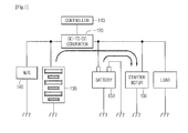
- FIG. 1 is a block diagram illustrating the flow of energy in an oscillating unit of a vehicle including an Ideal Stop & Go (ISG) system, according to an embodiment
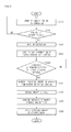
- FIG. 2 is a flowchart illustrating an initial driving operation of a vehicle, according to an embodiment
- FIG. 3 is a block diagram illustrating the flow of energy in an oscillating unit of a vehicle including an ISG system, according to another embodiment
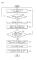
- FIG. 4 is a flowchart illustrating an initial driving operation of a vehicle, according to another embodiment
- FIG. 5 is a block diagram illustrating the flow of energy in an oscillating unit of a vehicle including an ISG system, according to another embodiment.
- FIG. 6 is a flowchart illustrating an initial driving operation of a vehicle, according to another embodiment.
- FIG. 1 is a block diagram illustrating the flow of energy in an oscillating unit of a vehicle including an Ideal Stop & Go (ISG) system, according to an embodiment.
- ISG Ideal Stop & Go
- the oscillating unit may include a controller 110, a direct current (DC)-to-DC converter 120, an energy storage 130, a motor/generator 140, a battery 150, and a starter motor 160.
- DC direct current
- the controller 110 may determine whether the DC-to-DC converter 120 is in a sleep mode and identify the period at which to wake up the DC-to-DC converter 120. When the DC-to-DC converter 120 operates in the sleep mode due to, for example, a long term of no use of the vehicle, the controller 110 may identify a predetermined wakeup period for the DC-to-DC converter 120, and may output a wakeup control signal to the DC-to-DC converter 120 upon the arrival of the predetermined wakeup period.
- the controller 110 may obtain state of charge (SOC) information of the energy storage 130 and the battery 150 from the DC-to-DC converter 120.
- SOC state of charge
- the controller 110 may control a critical amount of energy in the battery 150 to be transferred to the energy storage 130 with reference to the SOC information.
- the controller 110 may control the starter motor 160 to be started with the remaining energy in the energy storage 130 and the battery 150, respectively.
- the DC-to-DC converter 120 may be woken up from the sleep mode at regular intervals of time in response to the receipt of a control signal from the controller 110.
- the DC-to-DC converter 120 may be woken up at regular intervals of time, and may then determine the remaining energies of the energy storage 130 and the battery 150 and output SOC information obtained by the determination to the controller 110.
- the energy storage 130 may store energy generated or recovered by the motor/generator 140, and may supply energy for the driving of an ISG function.
- the energy storage 130 may be charged with the critical amount of energy from the battery 150.
- the energy with which the energy storage 130 is charged may be transmitted to the starter motor 160 so as to start the starter motor 160.
- the motor/generator 140 may execute an ISG mode by driving a motor engine, such as an alternator (AT) or a Side Starter Generator (SSG), with the energy present in the energy storage 130.
- a motor engine such as an alternator (AT) or a Side Starter Generator (SSG)
- the battery 150 may supply energy for driving the starter motor 160 for an initial start of the vehicle.
- the battery 150 may transmit the critical amount of energy to the energy storage 130 in accordance with monitoring result data from the DC-to-DC converter 120.
- the starter motor 160 may be driven with the energy from the battery 150 for an initial start of the vehicle.
- the starter motor 160 may also be driven with a combined energy obtained by combining the remaining energies of the battery 150 and the energy storage 130.
- FIGS. 1 and 2 An initial driving operation of a vehicle, according to an embodiment will hereinafter be described with reference to FIGS. 1 and 2 .
- FIG. 2 is a flowchart illustrating an initial driving operation of a vehicle, according to an embodiment.
- the controller 110 determines whether the DC-to-DC converter 120 is in a sleep mode and identifies a wakeup period for the DC-to-DC converter 120 (S210).
- the controller 110 determines whether the wakeup period has arrived (S220).
- the controller 110 wakes up the DC-to-DC converter 120 from the sleep mode (S230).
- the controller 110 obtains SOC information of the energy storage 130 and the battery 150 from the DC-to-DC converter 120 (S240).
- the controller 110 determines whether the remaining energies of the energy storage 130 and the battery 150 are lower a predetermined threshold based on the obtained SOC information (S250).
- the predetermined threshold may indicate a minimum amount of energy required to drive the motor/generator 140 or the starter motor 160.
- the controller 110 controls a critical amount of energy to be transmitted from the battery 150 to the energy storage 130 (S260).
- the critical amount of energy may account for a predetermined percentage of the remaining energy of the battery 150.
- the critical amount of energy may be set to, but is not limited to, 5% of the remaining energy of the battery 150.
- the critical amount of energy may vary depending on the amount of energy required for an initial start of the vehicle.
- the storage capacity of the energy storage 130 is less than the storage capacity of the battery 150.
- the energy storage 130 since the energy storage 130 has excellent current discharge capability as compared to the battery 150, the energy storage 130 can output a current with a high magnitude even at a low voltage. Accordingly, the energy storage 130 may outperform the battery 150 in terms of the magnitude of a current that can be output with any given output energy.
- the controller 110 controls the energy storage 130 to be charged with the critical amount of energy from the battery 150 (S270).
- the controller 110 obtains a combined energy by combining the remaining energies of the energy storage 130 and the battery 150 (S280).
- the controller 110 applies the combined energy to the starter motor 160 so that the starter motor 160 can be started upon an initial driving request.
- a combined energy obtained by combining the remaining energies of the energy storage 130 and the battery 150 is applied to the starter motor 160 to start the vehicle.
- FIG. 3 is a block diagram illustrating the flow of energy in an oscillating unit of a vehicle including an ISG system, according to another embodiment.
- the structure of the oscillating unit illustrated in FIG. 3 is similar to the structure of the oscillating unit illustrated in FIG. 1 .
- a controller 110 may determine whether a DC-to-DC converter 120 is in a sleep mode and identify the period at which to wake up the DC-to-DC converter 120.
- the controller 110 may identify a predetermined wakeup period for the DC-to-DC converter 120, and may output a wakeup control signal to the DC-to-DC converter 120 upon the arrival of the predetermined wakeup period.
- the controller 110 may obtain SOC information of an energy storage 130 and a battery 150 from the DC-to-DC converter 120.
- the controller 110 may control a starter motor 160 to be driven with the remaining energy of the energy storage 130 if the remaining energy of the battery 150 is not sufficient to drive the start motor 160.
- the DC-to-DC converter 10 may be woken up from the sleep mode at regular intervals of time in response to the receipt of a control signal from the controller 110.
- the DC-to-DC converter 120 may be woken up at regular intervals of time, and may then determine the remaining energies of the energy storage 130 and the battery 150 and output SOC information obtained by the determination to the controller 110.
- the energy storage 130 may store energy generated or recovered by the motor/generator 140, and may supply energy for the driving of an ISG function.
- the energy storage 130 may also supply energy for starting the starter motor 160.
- the motor/generator 140 may execute an ISG mode by driving a motor engine, such as an AT or a SSG, with the energy present in the energy storage 130.
- a motor engine such as an AT or a SSG
- the battery 150 may supply energy for driving the starter motor 160 for an initial start of the vehicle.
- the starter motor 160 may start the vehicle with the energy from the battery 150.
- the starter motor 160 may also start the vehicle with the energy from the energy storage 130.
- FIG. 4 is a flowchart illustrating an initial driving operation of a vehicle, according to another embodiment.
- the controller 110 determines whether the DC-to-DC converter 120 is in a sleep mode and identifies a wakeup period for the DC-to-DC converter 120 (S410).
- the controller 110 determines whether the wakeup period has arrived (S420). In response to a determination being made that the wakeup period has arrived, the controller 110 switches the DC-to-DC converter 120 from the sleep mode to a wakeup mode (S430).
- the controller 110 identifies the remaining energies of the energy storage 130 and the battery 150 from the DC-to-DC converter 120 (S440), and determines whether the remaining energies of the energy storage 130 and the battery 150 are lower a predetermined threshold (S450).
- the controller 110 controls a critical amount of energy in the battery 150 to be transmitted to the energy storage 130 (S460).
- the controller 110 controls the energy storage 130 to be charged with the critical amount of energy from the battery 150 (S470).
- the controller 110 controls the remaining energy of the energy storage 130 to be applied to the starter motor 160 (S480).
- the energy storage 130 Since the energy storage 130 has excellent current discharge capability as compared to the battery 150, the energy storage 130 can output a current with a high magnitude even at a low voltage. Accordingly, the energy storage 130 can provide a higher energy output than the battery 150 by using only a small portion of the energy of the battery 150. Therefore, the starter motor 160 can be started with the energy from the energy storage 130.
- FIG. 5 is a block diagram illustrating the flow of energy in an oscillating unit of a vehicle including an ISG system, according to another embodiment.
- the oscillating unit may include a controller 110, a direct current (DC)-to-DC converter 120, an energy storage 130, a starter motor 170, and a battery 150.
- the controller 110 may determine whether the DC-to-DC converter 120 is in a sleep mode and identify the period at which to wake up the DC-to-DC converter 120. When the DC-to-DC converter 120 operates in the sleep mode due to, for example, a long term of no use of the vehicle, the controller 110 may identify a predetermined wakeup period for the DC-to-DC converter 120, and may output a wakeup control signal to the DC-to-DC converter 120 upon the arrival of the predetermined wakeup period.
- the controller 110 may obtain SOC information of the energy storage 130 and the battery 150 from the DC-to-DC converter 120.
- the controller 110 may control a critical amount of energy in the battery 150 to be transferred to the energy storage 130 with reference to the SOC information.
- the controller 110 may control energy to be supplied from the energy storage 130 to the starter motor 170.
- the DC-to-DC converter 120 may be woken up from the sleep mode at regular intervals of time in response to the receipt of a control signal from the controller 110.
- the DC-to-DC converter 120 may be woken up at regular intervals of time, and may then determine the remaining energies of the energy storage 130 and the battery 150 and output SOC information obtained by the determination to the controller 110.
- the energy storage 130 may store energy generated or recovered by the starter motor 170, and may supply energy for the driving of an ISG function of the starter motor 170.
- the starter motor 170 may execute an ISG mode by using the energy present in the energy storage 130 for driving a motor engine, such as an AT or a SSG.
- the starter motor 170 may start the vehicle with the remaining energy of the battery 150.
- the battery 150 may supply the starter motor 170 with energy for an initial start of the vehicle.
- the battery 150 may transmit the critical amount of energy to the energy storage 130 in accordance with monitoring result data from the DC-to-DC converter 120.
- FIG. 6 is a flowchart illustrating an initial driving operation of a vehicle, according to another embodiment.
- the controller 110 determines whether the DC-to-DC converter 120 is in a sleep mode and identifies a wakeup period for the DC-to-DC converter 120 (S602).
- the controller 110 determines whether the wakeup period has arrived (S604).
- the controller 110 wakes up the DC-to-DC converter 120 from the sleep mode (S606).
- the controller 110 obtains SOC information of the energy storage 130 and the battery 150 from the DC-to-DC converter 120 (S608).
- the controller 110 determines whether the remaining energies of the energy storage 130 and the battery 150 are lower a predetermined threshold based on the obtained SOC information (S610).
- the predetermined threshold may indicate a minimum amount of energy required to drive the starter motor 170.
- the controller 110 controls a critical amount of energy to be transmitted from the battery 150 to the energy storage 130 (S612).
- the critical amount of energy may account for a predetermined percentage of the remaining energy of the battery 150.
- the critical amount of energy may vary depending on the amount of energy required for an initial start of the vehicle.
- the energy storage 130 Since the storage capacity of the energy storage 130 is less than the storage capacity of the battery 150 and can output a current with a high magnitude even at a low voltage due to its excellent current discharge capability, only a portion of the remaining battery 150 is transmitted to the energy storage 130. Accordingly, the energy storage 130 can provide a higher energy output than the battery 150 by using only a small portion of the energy of the battery 150.
- the controller 110 controls the energy storage 130 to be charged with the critical amount of energy from the battery 150 (S614).
- the controller 110 applies the energy in the energy storage 130 (S616).
- the controller 110 generates a control signal for an initial start of the vehicle and controls the vehicle to be started (S618).
- a critical amount of energy can be transmitted from the battery 150 to the energy storage 130, and the energy that the energy storage 130 is charged with can be applied to the starter motor 170 so that the vehicle can be started.
Landscapes
- Engineering & Computer Science (AREA)
- Power Engineering (AREA)
- Mechanical Engineering (AREA)
- Chemical & Material Sciences (AREA)
- Combustion & Propulsion (AREA)
- General Engineering & Computer Science (AREA)
- Transportation (AREA)
- Electric Propulsion And Braking For Vehicles (AREA)
- Charge And Discharge Circuits For Batteries Or The Like (AREA)
- Secondary Cells (AREA)
Abstract
Description
- This application claims priority under 35 U.S.C. § 119 from Korean Patent Application No.
10-2007-0038396, filed on April 19, 2007 - Embodiments relate to an initial starting apparatus and method for a vehicle.
- Due to the rapidly increasing oil prices and taxes, automobiles with maximized fuel efficiency, such as those equipped with an Idle Stop & Go (ISG) system, have been developed.
- Unlike a typical starter motor for a vehicle, a side starter generator (SSG) of an ISG system, which is a starter-alternator hybrid motor, serves as an alternator when an engine operates. An ISG system may be classified into an integrated type with an alternator and a starter incorporated thereinto and a separate type with an alternator and a starter provided therein separately.
- An ISG system can provide high fuel efficiency by turning off the engine of a vehicle when the vehicle is not driven and allowing the vehicle to be started with simple manipulation.
- However, in a vehicle to which an ISG system is applied, a starter motor consumes a high current when the vehicle is started. However, if the starter motor instantaneously consumes more energy than a permissible amount of energy, the starter motor may be dropped. In addition, the vehicle may not be started due to the driver's mistake or a dead or weak battery from a long term of no use.
- That is, a vehicle is started by a starter motor using the energy from a battery. However, if due to, for example, a long term of no use of the vehicle, the battery is dead or there is no sufficient energy left for the starter motor to be driven, the vehicle cannot be started.
- In one embodiment, an initial starting apparatus for a vehicle includes: a converter configured to identify remaining energy of an energy storage or a battery during a wakeup mode; a controller configured to control the wakeup mode of the converter and control energy to be applied from at least one of the energy storage and the battery to a starter motor in accordance with the remaining energies of the energy storage and the battery; the energy storage configured to apply energy to the starter motor under the control of the controller; the battery; and the starter motor configured to be driven by being supplied with energy by at least one of the energy storage and the battery.
- The above and/or other aspects will be more apparent by describing certain exemplary embodiments with reference to the accompanying drawings, in which:
-
FIG. 1 is a block diagram illustrating the flow of energy in an oscillating unit of a vehicle including an Ideal Stop & Go (ISG) system, according to an embodiment; -
FIG. 2 is a flowchart illustrating an initial driving operation of a vehicle, according to an embodiment; -
FIG. 3 is a block diagram illustrating the flow of energy in an oscillating unit of a vehicle including an ISG system, according to another embodiment; -
FIG. 4 is a flowchart illustrating an initial driving operation of a vehicle, according to another embodiment; -
FIG. 5 is a block diagram illustrating the flow of energy in an oscillating unit of a vehicle including an ISG system, according to another embodiment; and -
FIG. 6 is a flowchart illustrating an initial driving operation of a vehicle, according to another embodiment. - Following description exemplifies only the principles of the present invention. Even if they are not described or illustrated clearly in the present specification, one of ordinary skill in the art can embody the principles of the present invention and invent various apparatuses within the concept and scope of the present invention. The conditional terms and embodiments presented in the present specification are intended only to make understood the concept of the present invention, and they are not limited to the embodiments and conditions mentioned in the specification.
- In addition, all the detailed description on the principles, viewpoints and embodiments and particular embodiments of the present invention should be understood to include structural and functional equivalents to them. The equivalents include not only the currently known equivalents but also those to be developed in future, that is, all devices invented to perform the same function, regardless of their structures.
-
FIG. 1 is a block diagram illustrating the flow of energy in an oscillating unit of a vehicle including an Ideal Stop & Go (ISG) system, according to an embodiment. - Referring to
FIG. 1 , the oscillating unit may include acontroller 110, a direct current (DC)-to-DC converter 120, anenergy storage 130, a motor/generator 140, abattery 150, and astarter motor 160. - The
controller 110 may determine whether the DC-to-DC converter 120 is in a sleep mode and identify the period at which to wake up the DC-to-DC converter 120. When the DC-to-DC converter 120 operates in the sleep mode due to, for example, a long term of no use of the vehicle, thecontroller 110 may identify a predetermined wakeup period for the DC-to-DC converter 120, and may output a wakeup control signal to the DC-to-DC converter 120 upon the arrival of the predetermined wakeup period. - Once the DC-to-
DC converter 120 is woken up, thecontroller 110 may obtain state of charge (SOC) information of theenergy storage 130 and thebattery 150 from the DC-to-DC converter 120. - The
controller 110 may control a critical amount of energy in thebattery 150 to be transferred to theenergy storage 130 with reference to the SOC information. - Then, the
controller 110 may control thestarter motor 160 to be started with the remaining energy in theenergy storage 130 and thebattery 150, respectively. - The DC-to-
DC converter 120 may be woken up from the sleep mode at regular intervals of time in response to the receipt of a control signal from thecontroller 110. The DC-to-DC converter 120 may be woken up at regular intervals of time, and may then determine the remaining energies of theenergy storage 130 and thebattery 150 and output SOC information obtained by the determination to thecontroller 110. - Various types of devices for storing and supplying energy, such as an ultracapacitor, an absorbent glass mat (AGM) battery, a Pb battery or a lithium battery, may be used as the
energy storage 130. Theenergy storage 130 may store energy generated or recovered by the motor/generator 140, and may supply energy for the driving of an ISG function. Theenergy storage 130 may be charged with the critical amount of energy from thebattery 150. The energy with which theenergy storage 130 is charged may be transmitted to thestarter motor 160 so as to start thestarter motor 160. - The motor/
generator 140 may execute an ISG mode by driving a motor engine, such as an alternator (AT) or a Side Starter Generator (SSG), with the energy present in theenergy storage 130. - The
battery 150 may supply energy for driving thestarter motor 160 for an initial start of the vehicle. Thebattery 150 may transmit the critical amount of energy to theenergy storage 130 in accordance with monitoring result data from the DC-to-DC converter 120. - The
starter motor 160 may be driven with the energy from thebattery 150 for an initial start of the vehicle. Thestarter motor 160 may also be driven with a combined energy obtained by combining the remaining energies of thebattery 150 and theenergy storage 130. - An initial driving operation of a vehicle, according to an embodiment will hereinafter be described with reference to
FIGS. 1 and2 . -
FIG. 2 is a flowchart illustrating an initial driving operation of a vehicle, according to an embodiment. - Referring to
FIG. 2 , when the vehicle is not in use for a long time, thecontroller 110 determines whether the DC-to-DC converter 120 is in a sleep mode and identifies a wakeup period for the DC-to-DC converter 120 (S210). - The
controller 110 determines whether the wakeup period has arrived (S220). - In response to a determination being made that the wakeup period has arrived, the
controller 110 wakes up the DC-to-DC converter 120 from the sleep mode (S230). - The
controller 110 obtains SOC information of theenergy storage 130 and thebattery 150 from the DC-to-DC converter 120 (S240). - The
controller 110 determines whether the remaining energies of theenergy storage 130 and thebattery 150 are lower a predetermined threshold based on the obtained SOC information (S250). The predetermined threshold may indicate a minimum amount of energy required to drive the motor/generator 140 or thestarter motor 160. - In response to a determination being made that the remaining energies of the
energy storage 130 and thebattery 150 are lower than the predetermined threshold, thecontroller 110 controls a critical amount of energy to be transmitted from thebattery 150 to the energy storage 130 (S260). - The critical amount of energy may account for a predetermined percentage of the remaining energy of the
battery 150. For example, the critical amount of energy may be set to, but is not limited to, 5% of the remaining energy of thebattery 150. The critical amount of energy may vary depending on the amount of energy required for an initial start of the vehicle. - The storage capacity of the
energy storage 130 is less than the storage capacity of thebattery 150. In addition, since theenergy storage 130 has excellent current discharge capability as compared to thebattery 150, theenergy storage 130 can output a current with a high magnitude even at a low voltage. Accordingly, theenergy storage 130 may outperform thebattery 150 in terms of the magnitude of a current that can be output with any given output energy. - The
controller 110 controls theenergy storage 130 to be charged with the critical amount of energy from the battery 150 (S270). - In response to the charging of the
energy storage 130 being complete, thecontroller 110 obtains a combined energy by combining the remaining energies of theenergy storage 130 and the battery 150 (S280). - The
controller 110 applies the combined energy to thestarter motor 160 so that thestarter motor 160 can be started upon an initial driving request. - According to the embodiments of
FIGS. 1 and2 , when the vehicle cannot be started because of, for example, a dead battery from a long term of no use of the vehicle, a combined energy obtained by combining the remaining energies of theenergy storage 130 and thebattery 150 is applied to thestarter motor 160 to start the vehicle. -
FIG. 3 is a block diagram illustrating the flow of energy in an oscillating unit of a vehicle including an ISG system, according to another embodiment. - The structure of the oscillating unit illustrated in
FIG. 3 is similar to the structure of the oscillating unit illustrated inFIG. 1 . - Referring to
FIG. 3 , acontroller 110 may determine whether a DC-to-DC converter 120 is in a sleep mode and identify the period at which to wake up the DC-to-DC converter 120. When the DC-to-DC converter 120 operates in the sleep mode due to, for example, a long term of no use of the vehicle, thecontroller 110 may identify a predetermined wakeup period for the DC-to-DC converter 120, and may output a wakeup control signal to the DC-to-DC converter 120 upon the arrival of the predetermined wakeup period. - Once the DC-to-
DC converter 120 is woken up, thecontroller 110 may obtain SOC information of anenergy storage 130 and abattery 150 from the DC-to-DC converter 120. - The
controller 110 may control astarter motor 160 to be driven with the remaining energy of theenergy storage 130 if the remaining energy of thebattery 150 is not sufficient to drive thestart motor 160. - The DC-to-DC converter 10 may be woken up from the sleep mode at regular intervals of time in response to the receipt of a control signal from the
controller 110. The DC-to-DC converter 120 may be woken up at regular intervals of time, and may then determine the remaining energies of theenergy storage 130 and thebattery 150 and output SOC information obtained by the determination to thecontroller 110. - Various types of devices for storing and supplying energy, such as an ultracapacitor, an AGM battery, a Pb battery or a lithium battery, may be used as the
energy storage 130. Theenergy storage 130 may store energy generated or recovered by the motor/generator 140, and may supply energy for the driving of an ISG function. Theenergy storage 130 may also supply energy for starting thestarter motor 160. - The motor/
generator 140 may execute an ISG mode by driving a motor engine, such as an AT or a SSG, with the energy present in theenergy storage 130. - The
battery 150 may supply energy for driving thestarter motor 160 for an initial start of the vehicle. - The
starter motor 160 may start the vehicle with the energy from thebattery 150. Thestarter motor 160 may also start the vehicle with the energy from theenergy storage 130. - An initial driving operation of a vehicle, according to another embodiment will hereinafter be described with reference to
FIGS. 3 and4 . -
FIG. 4 is a flowchart illustrating an initial driving operation of a vehicle, according to another embodiment. - Referring to
FIG. 4 , thecontroller 110 determines whether the DC-to-DC converter 120 is in a sleep mode and identifies a wakeup period for the DC-to-DC converter 120 (S410). - The
controller 110 determines whether the wakeup period has arrived (S420). In response to a determination being made that the wakeup period has arrived, thecontroller 110 switches the DC-to-DC converter 120 from the sleep mode to a wakeup mode (S430). - The
controller 110 identifies the remaining energies of theenergy storage 130 and thebattery 150 from the DC-to-DC converter 120 (S440), and determines whether the remaining energies of theenergy storage 130 and thebattery 150 are lower a predetermined threshold (S450). - In response to a determination being made that the remaining energy of the
battery 150 is lower than the predetermined threshold, thecontroller 110 controls a critical amount of energy in thebattery 150 to be transmitted to the energy storage 130 (S460). - The
controller 110 controls theenergy storage 130 to be charged with the critical amount of energy from the battery 150 (S470). - In response to the remaining energy of the
energy storage 130 being lower than the predetermined threshold, thecontroller 110 controls the remaining energy of theenergy storage 130 to be applied to the starter motor 160 (S480). - Since the
energy storage 130 has excellent current discharge capability as compared to thebattery 150, theenergy storage 130 can output a current with a high magnitude even at a low voltage. Accordingly, theenergy storage 130 can provide a higher energy output than thebattery 150 by using only a small portion of the energy of thebattery 150. Therefore, thestarter motor 160 can be started with the energy from theenergy storage 130. -
FIG. 5 is a block diagram illustrating the flow of energy in an oscillating unit of a vehicle including an ISG system, according to another embodiment. - Referring to
FIG. 5 , the oscillating unit may include acontroller 110, a direct current (DC)-to-DC converter 120, anenergy storage 130, astarter motor 170, and abattery 150. - The
controller 110 may determine whether the DC-to-DC converter 120 is in a sleep mode and identify the period at which to wake up the DC-to-DC converter 120. When the DC-to-DC converter 120 operates in the sleep mode due to, for example, a long term of no use of the vehicle, thecontroller 110 may identify a predetermined wakeup period for the DC-to-DC converter 120, and may output a wakeup control signal to the DC-to-DC converter 120 upon the arrival of the predetermined wakeup period. - Once the DC-to-
DC converter 120 is woken up, thecontroller 110 may obtain SOC information of theenergy storage 130 and thebattery 150 from the DC-to-DC converter 120. - The
controller 110 may control a critical amount of energy in thebattery 150 to be transferred to theenergy storage 130 with reference to the SOC information. - The
controller 110 may control energy to be supplied from theenergy storage 130 to thestarter motor 170. - The DC-to-
DC converter 120 may be woken up from the sleep mode at regular intervals of time in response to the receipt of a control signal from thecontroller 110. The DC-to-DC converter 120 may be woken up at regular intervals of time, and may then determine the remaining energies of theenergy storage 130 and thebattery 150 and output SOC information obtained by the determination to thecontroller 110. - Various types of devices for storing and supplying energy, such as an ultracapacitor, an AGM battery, a Pb battery or a lithium battery, may be used as the
energy storage 130. Theenergy storage 130 may store energy generated or recovered by thestarter motor 170, and may supply energy for the driving of an ISG function of thestarter motor 170. - The
starter motor 170 may execute an ISG mode by using the energy present in theenergy storage 130 for driving a motor engine, such as an AT or a SSG. Thestarter motor 170 may start the vehicle with the remaining energy of thebattery 150. - The
battery 150 may supply thestarter motor 170 with energy for an initial start of the vehicle. Thebattery 150 may transmit the critical amount of energy to theenergy storage 130 in accordance with monitoring result data from the DC-to-DC converter 120. - An initial driving operation of a vehicle, according to another embodiment will hereinafter be described with reference to
FIGS. 5 and6 . -
FIG. 6 is a flowchart illustrating an initial driving operation of a vehicle, according to another embodiment. - Referring to
FIG. 6 , thecontroller 110 determines whether the DC-to-DC converter 120 is in a sleep mode and identifies a wakeup period for the DC-to-DC converter 120 (S602). - The
controller 110 determines whether the wakeup period has arrived (S604). - In response to a determination being made that the wakeup period has arrived, the
controller 110 wakes up the DC-to-DC converter 120 from the sleep mode (S606). - The
controller 110 obtains SOC information of theenergy storage 130 and thebattery 150 from the DC-to-DC converter 120 (S608). - The
controller 110 determines whether the remaining energies of theenergy storage 130 and thebattery 150 are lower a predetermined threshold based on the obtained SOC information (S610). The predetermined threshold may indicate a minimum amount of energy required to drive thestarter motor 170. - In response to a determination being made that the remaining energies of the
energy storage 130 and thebattery 150 are lower than the predetermined threshold, thecontroller 110 controls a critical amount of energy to be transmitted from thebattery 150 to the energy storage 130 (S612). - The critical amount of energy may account for a predetermined percentage of the remaining energy of the
battery 150. The critical amount of energy may vary depending on the amount of energy required for an initial start of the vehicle. - Since the storage capacity of the
energy storage 130 is less than the storage capacity of thebattery 150 and can output a current with a high magnitude even at a low voltage due to its excellent current discharge capability, only a portion of the remainingbattery 150 is transmitted to theenergy storage 130. Accordingly, theenergy storage 130 can provide a higher energy output than thebattery 150 by using only a small portion of the energy of thebattery 150. - The
controller 110 controls theenergy storage 130 to be charged with the critical amount of energy from the battery 150 (S614). - In response to the charging of the
energy storage 130 being complete, thecontroller 110 applies the energy in the energy storage 130 (S616). - The
controller 110 generates a control signal for an initial start of the vehicle and controls the vehicle to be started (S618). - According to the embodiments of
FIGS. 5 and6 , when the vehicle cannot be started because of, for example, a dead battery from a long term of no use of the vehicle, a critical amount of energy can be transmitted from thebattery 150 to theenergy storage 130, and the energy that theenergy storage 130 is charged with can be applied to thestarter motor 170 so that the vehicle can be started. - Although embodiments have been described with reference to a number of illustrative embodiments thereof, it should be understood that numerous other modifications and embodiments can be devised by those skilled in the art that will fall within the spirit and scope of the principles of this disclosure. More particularly, various variations and modifications are possible in the component parts and/or arrangements of the subject combination arrangement within the scope of the disclosure, the drawings and the appended claims. In addition to variations and modifications in the component parts and/or arrangements, alternative uses will also be apparent to those skilled in the art.
Claims (10)
- An initial starting apparatus for a vehicle, comprising:a converter configured to identify remaining energy of an energy storage or a battery during a wakeup mode;a controller configured to control the wakeup mode of the converter and control energy to be applied from at least one of the energy storage and the battery to a starter motor in accordance with the remaining energies of the energy storage and the battery;the energy storage configured to apply energy to the starter motor under the control of the controller;the battery; andthe starter motor configured to be driven by being supplied with energy by at least one of the energy storage and the battery.
- The initial starting apparatus of claim 1, wherein the controller is further configured to switch the converter from a sleep mode to the wakeup mode at intervals of a predetermined period in response to the converter continuing to operate in the sleep mode for a predetermined amount of time.
- The initial starting apparatus of claim 2, wherein the controller is further configured to identify the remaining energies of the energy storage and the battery in response to the converter being switched from the sleep mode to the wakeup mode.
- The initial starting apparatus of claim 1, wherein the controller is further configured to control a combined energy obtained by combining the energies from the energy storage and the battery to be applied to the starter motor.
- The initial starting apparatus of claim 4, wherein the energy storage is further configured to be supplied and charged with a critical amount of energy applied thereto by the battery in accordance with the identified remaining energies and then supply energy to the starter motor.
- The initial starting apparatus of claim 5, wherein the controller is further configured to transmit a critical amount of energy from the battery to the energy storage in response to the remaining energy of the battery being lower than a predetermined threshold.
- The initial starting apparatus of claim 1, wherein the controller is further configured to apply energy from the energy storage to the starter motor in accordance with the remaining energies of the energy storage and the battery.
- An initial starting method for a vehicle, comprising:identifying remaining energy of an energy storage or a battery during a wakeup mode;transmitting energy from the battery to the energy storage in response to the remaining energy of the energy storage or the battery being lower than a predetermined threshold;charging the energy storage with the transmitted energy; andsupplying the energy that the energy storage is charged with to a motor.
- The initial starting method of claim 8, wherein the identifying comprise:determining whether a converter is in a sleep mode and identifying a wakeup period for the converter;determining whether the wakeup period has arrived; andidentifying the remaining energy of the energy storage or the battery in response to the converter being woken up.
- The initial starting method of claim 8, wherein the predetermined threshold is a minimum amount of energy required to start the vehicle.
Applications Claiming Priority (1)
| Application Number | Priority Date | Filing Date | Title |
|---|---|---|---|
| KR1020120121616A KR101323916B1 (en) | 2012-10-30 | 2012-10-30 | Apparatus and method for early starting of vehicle |
Publications (2)
| Publication Number | Publication Date |
|---|---|
| EP2728703A2 true EP2728703A2 (en) | 2014-05-07 |
| EP2728703A3 EP2728703A3 (en) | 2017-06-21 |
Family
ID=49474272
Family Applications (1)
| Application Number | Title | Priority Date | Filing Date |
|---|---|---|---|
| EP13189870.2A Withdrawn EP2728703A3 (en) | 2012-10-30 | 2013-10-23 | Initial starting apparatus and method for vehicle |
Country Status (5)
| Country | Link |
|---|---|
| US (1) | US20140117890A1 (en) |
| EP (1) | EP2728703A3 (en) |
| JP (1) | JP5695162B2 (en) |
| KR (1) | KR101323916B1 (en) |
| CN (1) | CN103790748B (en) |
Cited By (2)
| Publication number | Priority date | Publication date | Assignee | Title |
|---|---|---|---|---|
| EP3081425A1 (en) * | 2015-04-13 | 2016-10-19 | LSIS Co., Ltd. | Vehicle power management device |
| EP3477095A1 (en) * | 2017-10-27 | 2019-05-01 | Hyundai Motor Company | Idle stop and go system and method controlling thereof |
Families Citing this family (7)
| Publication number | Priority date | Publication date | Assignee | Title |
|---|---|---|---|---|
| CN103192717B (en) * | 2013-04-09 | 2015-06-10 | 郑州宇通客车股份有限公司 | Low-voltage power supply system of hybrid power automobile and control method thereof |
| US11293662B2 (en) * | 2016-12-08 | 2022-04-05 | Belimo Holding Ag | HVAC actuator |
| CN106894932A (en) * | 2017-03-01 | 2017-06-27 | 奇瑞汽车股份有限公司 | Vehicle startup system and its startup method |
| CN109586368B (en) * | 2018-12-07 | 2020-09-15 | 珠海格力电器股份有限公司 | Energy storage system starting device, starting method and energy storage system |
| CN110594069B (en) * | 2019-08-22 | 2021-05-07 | 中国第一汽车股份有限公司 | Engine starting and energy recovery system and control method thereof |
| CN111332233A (en) * | 2020-03-26 | 2020-06-26 | 重庆长安汽车股份有限公司 | Automobile start-stop system and energy recovery system based on super capacitor |
| IT202200018462A1 (en) * | 2022-09-12 | 2024-03-12 | Ferrari Spa | ROAD VEHICLE EQUIPPED WITH A DC-DC ELECTRONIC POWER CONVERTER AND CORRESPONDING CONTROL METHOD |
Family Cites Families (23)
| Publication number | Priority date | Publication date | Assignee | Title |
|---|---|---|---|---|
| JPS5861042A (en) * | 1981-10-07 | 1983-04-11 | Futamura Shoji | Power supply device of car |
| JP3097482B2 (en) * | 1995-01-13 | 2000-10-10 | トヨタ自動車株式会社 | Retarder device |
| JP3549806B2 (en) * | 2000-03-01 | 2004-08-04 | 株式会社日立製作所 | Automotive power supply controller |
| US6323608B1 (en) * | 2000-08-31 | 2001-11-27 | Honda Giken Kogyo Kabushiki Kaisha | Dual voltage battery for a motor vehicle |
| US6420793B1 (en) * | 2000-09-21 | 2002-07-16 | Ford Global Technologies, Inc. | Power delivery circuit with boost for energetic starting in a pulsed charge starter/alternator system |
| US6717291B2 (en) * | 2000-10-10 | 2004-04-06 | Purkey's Electrical Consulting | Capacitor-based powering system and associated methods |
| US7378818B2 (en) * | 2002-11-25 | 2008-05-27 | Tiax Llc | Bidirectional power converter for balancing state of charge among series connected electrical energy storage units |
| US7202574B2 (en) * | 2004-06-14 | 2007-04-10 | C.E. Niehoff & Co. | System and method for electrical energy switching and control in a vehicle |
| US7908891B2 (en) * | 2004-07-16 | 2011-03-22 | Ansell Healthcare Products Llc | Knitted glove |
| JP4211715B2 (en) * | 2004-08-23 | 2009-01-21 | 株式会社デンソー | In-vehicle power supply system |
| TWI246099B (en) * | 2004-12-07 | 2005-12-21 | Luxon Energy Devices Corp | Power supply apparatus and power supply method |
| JP4475138B2 (en) * | 2005-02-24 | 2010-06-09 | トヨタ自動車株式会社 | Internal combustion engine starter and vehicle |
| JP2008190322A (en) * | 2005-05-13 | 2008-08-21 | Matsushita Electric Ind Co Ltd | Engine starter |
| JP2008190324A (en) * | 2005-05-13 | 2008-08-21 | Matsushita Electric Ind Co Ltd | Engine starter |
| WO2006123682A1 (en) * | 2005-05-17 | 2006-11-23 | Matsushita Electric Industrial Co., Ltd. | Engine start device |
| US7638079B2 (en) * | 2005-11-28 | 2009-12-29 | Microflex Corporation | Thin wall glove with thicker cuff |
| US20070252435A1 (en) * | 2006-04-26 | 2007-11-01 | Carlos Coe | High capacity mobile electric power source |
| US7806095B2 (en) * | 2007-08-31 | 2010-10-05 | Vanner, Inc. | Vehicle starting assist system |
| JP2010124581A (en) * | 2008-11-19 | 2010-06-03 | Panasonic Corp | Vehicle power supply |
| WO2010131352A1 (en) * | 2009-05-14 | 2010-11-18 | トヨタ自動車株式会社 | Electric car and method for controlling the same |
| JP4797092B2 (en) * | 2009-07-02 | 2011-10-19 | 本田技研工業株式会社 | Fuel cell vehicle and control method of fuel cell system |
| JP5293841B2 (en) * | 2010-02-09 | 2013-09-18 | トヨタ自動車株式会社 | Electric vehicle power supply system and control method thereof |
| JP5084864B2 (en) * | 2010-04-28 | 2012-11-28 | 三菱電機株式会社 | Idle stop car power control device |
-
2012
- 2012-10-30 KR KR1020120121616A patent/KR101323916B1/en not_active Expired - Fee Related
-
2013
- 2013-10-23 EP EP13189870.2A patent/EP2728703A3/en not_active Withdrawn
- 2013-10-23 US US14/061,538 patent/US20140117890A1/en not_active Abandoned
- 2013-10-28 JP JP2013223127A patent/JP5695162B2/en not_active Expired - Fee Related
- 2013-10-30 CN CN201310528667.4A patent/CN103790748B/en not_active Expired - Fee Related
Non-Patent Citations (1)
| Title |
|---|
| None |
Cited By (2)
| Publication number | Priority date | Publication date | Assignee | Title |
|---|---|---|---|---|
| EP3081425A1 (en) * | 2015-04-13 | 2016-10-19 | LSIS Co., Ltd. | Vehicle power management device |
| EP3477095A1 (en) * | 2017-10-27 | 2019-05-01 | Hyundai Motor Company | Idle stop and go system and method controlling thereof |
Also Published As
| Publication number | Publication date |
|---|---|
| CN103790748A (en) | 2014-05-14 |
| JP5695162B2 (en) | 2015-04-01 |
| EP2728703A3 (en) | 2017-06-21 |
| CN103790748B (en) | 2016-05-04 |
| US20140117890A1 (en) | 2014-05-01 |
| KR101323916B1 (en) | 2013-10-31 |
| JP2014088171A (en) | 2014-05-15 |
Similar Documents
| Publication | Publication Date | Title |
|---|---|---|
| US20140117890A1 (en) | Initial starting apparatus and method for vehicle | |
| JP7091830B2 (en) | Power supply | |
| CN107985229B (en) | Battery management system and control method thereof | |
| US9797361B2 (en) | Power supply device for vehicle | |
| CN105934861B (en) | Vehicle power grid | |
| CN105799694B (en) | Control method, system and the vehicle of vehicle | |
| US20150336523A1 (en) | Vehicle power supply apparatus and vehicle power regeneration system | |
| KR102007835B1 (en) | Power supply of Battery Management System | |
| US20150336474A1 (en) | Vehicle power supply apparatus and vehicle power regeneration system | |
| CN102341265B (en) | Apparatus and method for controlling a relay in a hybrid vehicle | |
| CN108422953A (en) | Automotive power supply system | |
| US9789771B2 (en) | Single battery architecture for electrification vehicle | |
| CN108501746A (en) | Battery pack heating means, apparatus and system | |
| JP2007064209A (en) | Engine control device, control method, and control system | |
| EP2773526A2 (en) | A dual energy storage system for micro hybrid vehicles | |
| CN105904978A (en) | Range extension type electric vehicle with double power battery packs | |
| US20150134231A1 (en) | System and method for vehicle start-stop | |
| US10075004B2 (en) | Battery jump-starting method | |
| US10324514B2 (en) | MCU wake-up device and method in sleep mode | |
| EP2907702A1 (en) | Vehicle battery system | |
| KR102209317B1 (en) | Electrical power supply device and method of operating same | |
| JP2008290513A (en) | Power control device and on-vehicle electronic equipment system | |
| KR101887748B1 (en) | System for protecting battery from over-charge for vehicle and the controlling method | |
| KR102496195B1 (en) | System and method for actively controlling power of vehicles | |
| JP4930420B2 (en) | In-vehicle power supply |
Legal Events
| Date | Code | Title | Description |
|---|---|---|---|
| PUAI | Public reference made under article 153(3) epc to a published international application that has entered the european phase |
Free format text: ORIGINAL CODE: 0009012 |
|
| 17P | Request for examination filed |
Effective date: 20131023 |
|
| AK | Designated contracting states |
Kind code of ref document: A2 Designated state(s): AL AT BE BG CH CY CZ DE DK EE ES FI FR GB GR HR HU IE IS IT LI LT LU LV MC MK MT NL NO PL PT RO RS SE SI SK SM TR |
|
| AX | Request for extension of the european patent |
Extension state: BA ME |
|
| PUAL | Search report despatched |
Free format text: ORIGINAL CODE: 0009013 |
|
| AK | Designated contracting states |
Kind code of ref document: A3 Designated state(s): AL AT BE BG CH CY CZ DE DK EE ES FI FR GB GR HR HU IE IS IT LI LT LU LV MC MK MT NL NO PL PT RO RS SE SI SK SM TR |
|
| AX | Request for extension of the european patent |
Extension state: BA ME |
|
| RIC1 | Information provided on ipc code assigned before grant |
Ipc: H02J 7/00 20060101AFI20170517BHEP Ipc: F02N 11/08 20060101ALI20170517BHEP Ipc: H02P 31/00 20060101ALI20170517BHEP |
|
| STAA | Information on the status of an ep patent application or granted ep patent |
Free format text: STATUS: THE APPLICATION IS DEEMED TO BE WITHDRAWN |
|
| 18D | Application deemed to be withdrawn |
Effective date: 20171222 |