EP2728675A1 - Female electrical terminal - Google Patents
Female electrical terminal Download PDFInfo
- Publication number
- EP2728675A1 EP2728675A1 EP13189238.2A EP13189238A EP2728675A1 EP 2728675 A1 EP2728675 A1 EP 2728675A1 EP 13189238 A EP13189238 A EP 13189238A EP 2728675 A1 EP2728675 A1 EP 2728675A1
- Authority
- EP
- European Patent Office
- Prior art keywords
- terminal
- sleeve
- female electrical
- electrical terminal
- blade
- Prior art date
- Legal status (The legal status is an assumption and is not a legal conclusion. Google has not performed a legal analysis and makes no representation as to the accuracy of the status listed.)
- Withdrawn
Links
- 239000004020 conductor Substances 0.000 claims abstract description 4
- 238000003780 insertion Methods 0.000 claims description 11
- 230000037431 insertion Effects 0.000 claims description 11
- 230000001681 protective effect Effects 0.000 claims description 8
- 230000014759 maintenance of location Effects 0.000 claims description 4
- 239000000463 material Substances 0.000 claims description 3
- 229910001220 stainless steel Inorganic materials 0.000 claims description 2
- 239000010935 stainless steel Substances 0.000 claims description 2
- 239000012212 insulator Substances 0.000 description 5
- 230000002829 reductive effect Effects 0.000 description 4
- 230000001012 protector Effects 0.000 description 3
- 230000004888 barrier function Effects 0.000 description 2
- 230000005540 biological transmission Effects 0.000 description 2
- 238000013459 approach Methods 0.000 description 1
- 238000005452 bending Methods 0.000 description 1
- 238000006073 displacement reaction Methods 0.000 description 1
- 230000002452 interceptive effect Effects 0.000 description 1
- 230000000670 limiting effect Effects 0.000 description 1
- 238000003825 pressing Methods 0.000 description 1
- 230000003068 static effect Effects 0.000 description 1
Images


Classifications
-
- H—ELECTRICITY
- H01—ELECTRIC ELEMENTS
- H01R—ELECTRICALLY-CONDUCTIVE CONNECTIONS; STRUCTURAL ASSOCIATIONS OF A PLURALITY OF MUTUALLY-INSULATED ELECTRICAL CONNECTING ELEMENTS; COUPLING DEVICES; CURRENT COLLECTORS
- H01R13/00—Details of coupling devices of the kinds covered by groups H01R12/70 or H01R24/00 - H01R33/00
- H01R13/02—Contact members
- H01R13/10—Sockets for co-operation with pins or blades
- H01R13/11—Resilient sockets
-
- H—ELECTRICITY
- H01—ELECTRIC ELEMENTS
- H01R—ELECTRICALLY-CONDUCTIVE CONNECTIONS; STRUCTURAL ASSOCIATIONS OF A PLURALITY OF MUTUALLY-INSULATED ELECTRICAL CONNECTING ELEMENTS; COUPLING DEVICES; CURRENT COLLECTORS
- H01R13/00—Details of coupling devices of the kinds covered by groups H01R12/70 or H01R24/00 - H01R33/00
- H01R13/02—Contact members
- H01R13/15—Pins, blades or sockets having separate spring member for producing or increasing contact pressure
- H01R13/18—Pins, blades or sockets having separate spring member for producing or increasing contact pressure with the spring member surrounding the socket
Definitions
- the present invention relates to a female electrical terminal that is intended for connection with a blade-type male terminal.
- FIG. 1 there is depicted a female electrical terminal as known from the prior art. Those terminals are characterized by comprising a portion that allows the connection with electrical cables 7 and a portion that allows the connection with a male terminal 8, normally of the blade type.
- the portion that allows the connection with a male terminal comprises a bottom, sidewalls, and internally, contact elements that provide the electrical connection with the blade of the male terminal to be connected.
- Those contact elements have a shape such that upon insertion of the blade they apply the necessary pressure to warrant the required efficiency in electrical transmission between the male terminal and the female terminal.
- the same have one or two contact elements in the shape of internal tabs for provision of electrical connection with the blade of the male terminal.
- Figure 2 there is depicted a terminal 5 in which the contact elements are manufactured such as to warrant that the fixed end 3 of the contact element 1 be located at the region of entry of the blade of the male terminal and the overhung end 4 be located inside the terminal.
- the arrow indicates the direction of insertion of the male terminal blade.
- Figure 2a shows a lateral section view of another terminal of that type, however with only one internal contact element 1. In this manner, the contact element 1 guides the insertion of the blade, thereby minimizing the stress required for establishment of the connection.
- FIGs 3 and 3a there are depicted terminals whose contact elements have their fixed ends 3 located in the rear region while the overhung ends 4 are located near the front region. That characteristic entails the risk that the blade of the male terminal might damage the female terminal at the time of connection if the same is introduced at certain angles of inclination. In order to obviate this type of damage there is used a protective barrier 2 at the entry of the terminal.
- Figure 3a shows a sectional view of a terminal of this type, where it may be clearly noted that without the protective barrier 2 the blade of the male terminal would not be guided towards a correct insertion into the female terminal.
- the object of the present invention consists in the provision of a female electrical terminal having small dimensions without thereby affecting either its mechanical integrity or its electrical transmission characteristics.
- the present invention provides a female electrical terminal devoid of at least one sidewall and which comprises a protective sleeve that fulfills the role of sidewall in lieu of the absent at least one sidewall
- a female electrical terminal in accordance with one embodiment of this invention, includes a portion that allows connection of the female terminal with an electrical conductor cable, a portion provided for connection with a blade type male terminal, and at least one internal contact element.
- the female terminal is devoid of at least one sidewall.
- the female terminal additionally includes a sleeve that performs the function of sidewall to substitute for the at least one absent sidewall of the terminal.
- Figure 1 shows a female terminal as known in the art
- Figure 2 shows a female terminal comprising contact elements that have a fixed end located at the point of entry, as known in the art
- Figure 2b shows a cross sectional view of a female terminal that comprises contact elements that have a fixed end located at the region of entry of the blade of the male terminal, as known in the art;
- Figure 3 shows a female terminal, which comprises contact elements that have a fixed end located inside the terminal as known in the art
- Figure 3a shows a sectional view of the terminal of Figure 3 ;
- Figure 4 shows cross sectional views of four different terminals as known in the art
- Figure 5 shows a perspective view of a preferred embodiment of the female terminal according to the present invention
- Figure 6 shows a side view of the female terminal depicted in Figure 5 ;
- Figure 7 shows a cross sectional view of the female terminal depicted in Figure 4 , with a sleeve and with a blade inserted therein;
- Figure 8 shows the female terminal with a sleeve affixed thereto
- Figure 9 shows a front view of the female terminal with a sleeve affixed thereto in its preferred embodiment
- Figure 10 shows a section along line A-A of the female terminal of Figure 7 with a blade inserted therein;
- Figure 11 shows a section along line B-B of the female terminal of Figure 7 ;
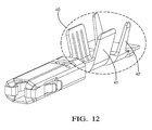
- Figure 12 shows a complete female terminal with the portion thereof that provides the connection to an electrical cable.
- the female terminal is of the type that comprises at least one internal contact element.
- Figure 5 shows a perspective view of a preferred embodiment of the female terminal 10, where the arrow indicates the direction of insertion of the blade 17 of the male terminal to be connected.
- the contact elements may have its fixed end located inside the terminal and may comprise a protective element at the point of entry in order to prevent the occurrence of damage.
- each contact element 11 is preferably provided with a protective element 15 against fatigue and/or inelastic deformation. That element may be formed and positioned, preferably, in alignment with the point of contact II of the contact element 11.
- the said protective element 15 may be positioned at any point of the sidewalls 16. However, it is preferable that the same be positioned near the fixed end 12 of the contact element 11, without interfering with its bending amplitude.
- each contact element 11 preferably has three inflexions (numbered from I to III) that cause the same to act as a spring, applying pressure on the blade 17 of the male terminal to be connected, in order to warrant the required quality of the electrical connection.
- FIG. 7 shows a female terminal according to this preferred embodiment with a blade 17 inserted therein, where there can be clearly seen what has been described above.
- the contact element 11 may have only two inflections, and thereby only the first spring would apply pressure on the blade 17, which could be sufficient in some applications.
- the female terminal 10 has no sidewalls in direction A. In that direction, the absence of the sidewalls does not interfere with the quality of the electrical connection.
- a protective sleeve 30 around the female terminal 10 is used.
- Such sleeve 30 is usually made of a material with a mechanical performance that is superior to that of the terminal to allow the thickness thereof to be reduced.
- the selected material is stainless steel.
- the number of absent sidewalls may be as many as might be deemed necessary for the application in each case, and the absent sidewall may be any sidewall of the terminal, considering the direction in which it is intended to have reduced dimensions.
- Figure 9 shows a front view of the female terminal 10 encased by the sleeve 30 with the representation, in dotted line, of a blade 17 inserted therein.
- the terminal has no sidewalls in the width direction of the blade 17. Since the thickness of the sleeve 30 is less than the thickness of the female terminal 10, it is ensured that the dimension of the assembly (female terminal 10 and sleeve 30), in the width direction of the blade 17, is less than the thickness of a female terminal equipped with all the sidewalls, as known in the art. In that situation, the sleeve 30, in addition to performing the function already known in the art, also performs the function of the absent sidewalls.
- Figure 10 shows a sectional view along the line A-A of Figure 9 , wherein there may be more clearly observed the inexistence of sidewalls of the female terminal 10, with the blade 17 being protected by the sleeve 30.
- the proposed terminal has reduced dimensions in one of its directions, allowing the connection of more terminals side by side, if such terminals are adequately positioned.
- FIG 11 there is shown a sectional view along the line B-B, where it is possible to note the existence of assembly retainers 36 on the outer face of the sleeve 30.
- Those assembly retainers 36 are provided to assist the retention of the sleeve 30 in the cavity of a plastic insulator wherein the same may be optionally inserted.
- retainers 36 may be provided together with retainer protectors 31.
- the function of such protectors is to avoid the occurrence of damage to the retainer at the time of insertion or removal of the terminal with sleeve from the plastic insulators.
- Those retainers and protectors may consist in mere protuberances, or any other element that allows the retention of the sleeves within cavities of plastic insulators without damaging the same.
- the female terminal 10 optionally has two openings 13 at the rear portion thereof Those openings 13 are intended to provide the retention of the sleeve 30, by means of fastening retainers 32 or tabs, present in the sleeve 30, that are bent towards the inside of the female terminal 10 and fit into the openings 13.
- Figure 9 it is also possible to observe the optional presence of a guide element 33 to guide the insertion of the male blade 17 towards each contact element 11. That guide element 33 is additionally intended for protection against direct impact on the terminal at the time of insertion of the blade 17. It is additionally noted that beside the guide elements 33 there exist two optional body positioning elements 34 that assist in securing the sleeve 30 to the female terminal 10. The utilization of those body positioning elements 34 together with the fastening retainers 32 assists the assembly to remain static.
- clips 35 to close the sleeve 30.
- Those clips 35 have a shape such that they fit snugly around the female terminal 10 on all lateral dimensions and provide an effective protection against impact.
- Such clips 35 may have any shape that might warrant the immobilization of the engagement in the directions x and y (indicated in the figure).
- an octagonal cross section shape of the assembly formed by the sleeve 30 and the female terminal 10 since this shape renders the assembly more effective when using a plastic insulator.
- other shapes may be chosen, such as a rectangular shape.
- any female terminal having the characteristics described herein will further have, at the rear portion 40 thereof, means for connection to electrical cables.
- that element is comprised of a conductor wing 41 and an insulator wing 42, as depicted in Figure 12 .
- the type of clamp that is actually used should be the most appropriate for the use for which the terminal is intended.
Landscapes
- Connector Housings Or Holding Contact Members (AREA)
- Details Of Connecting Devices For Male And Female Coupling (AREA)
Abstract
Description
- The present invention relates to a female electrical terminal that is intended for connection with a blade-type male terminal.
- In
Figure 1 there is depicted a female electrical terminal as known from the prior art. Those terminals are characterized by comprising a portion that allows the connection withelectrical cables 7 and a portion that allows the connection with amale terminal 8, normally of the blade type. - The portion that allows the connection with a male terminal comprises a bottom, sidewalls, and internally, contact elements that provide the electrical connection with the blade of the male terminal to be connected. Those contact elements have a shape such that upon insertion of the blade they apply the necessary pressure to warrant the required efficiency in electrical transmission between the male terminal and the female terminal.
- In the known configurations of those terminals, the same have one or two contact elements in the shape of internal tabs for provision of electrical connection with the blade of the male terminal.
- In
Figure 2 there is depicted aterminal 5 in which the contact elements are manufactured such as to warrant that the fixedend 3 of thecontact element 1 be located at the region of entry of the blade of the male terminal and theoverhung end 4 be located inside the terminal. The arrow indicates the direction of insertion of the male terminal blade.Figure 2a shows a lateral section view of another terminal of that type, however with only oneinternal contact element 1. In this manner, thecontact element 1 guides the insertion of the blade, thereby minimizing the stress required for establishment of the connection. - In
Figures 3 and 3a there are depicted terminals whose contact elements have theirfixed ends 3 located in the rear region while theoverhung ends 4 are located near the front region. That characteristic entails the risk that the blade of the male terminal might damage the female terminal at the time of connection if the same is introduced at certain angles of inclination. In order to obviate this type of damage there is used aprotective barrier 2 at the entry of the terminal.Figure 3a shows a sectional view of a terminal of this type, where it may be clearly noted that without theprotective barrier 2 the blade of the male terminal would not be guided towards a correct insertion into the female terminal. - There is further noted, in all prior art terminals, the existence of sidewalls along the transversal directions x and y, as illustrated in
Figure 4 , wherein are the shown cross sections of 4 different terminals. When those terminals are connected side by side, the presence of sidewalls poses a serious problem to the industry, since those sidewalls entail a significant increase of the final dimension of the set of terminals. - Thus, there is a need in the art of a female electrical terminal having reduced dimensions in at least one direction.
- The subject matter discussed in the background section should not be assumed to be prior art merely as a result of its mention in the background section. Similarly, a problem mentioned in the background section or associated with the subject matter of the background section should not be assumed to have been previously recognized in the prior art. The subject matter in the background section merely represents different approaches, which in and of themselves may also be inventions.
- In light of the problems having been set forth above, the object of the present invention consists in the provision of a female electrical terminal having small dimensions without thereby affecting either its mechanical integrity or its electrical transmission characteristics.
- In order to achieve the above objects, the present invention provides a female electrical terminal devoid of at least one sidewall and which comprises a protective sleeve that fulfills the role of sidewall in lieu of the absent at least one sidewall
- In accordance with one embodiment of this invention, a female electrical terminal is provided. The female electrical terminal includes a portion that allows connection of the female terminal with an electrical conductor cable, a portion provided for connection with a blade type male terminal, and at least one internal contact element. The female terminal is devoid of at least one sidewall. The female terminal additionally includes a sleeve that performs the function of sidewall to substitute for the at least one absent sidewall of the terminal.
- Further features and advantages of the invention will appear more clearly on a reading of the following detailed description of the preferred embodiment of the invention, which is given by way of non-limiting example only and with reference to the accompanying drawings.
- The present invention will now be described, by way of example with reference to the accompanying drawings, in which:
-
Figure 1 shows a female terminal as known in the art; -
Figure 2 shows a female terminal comprising contact elements that have a fixed end located at the point of entry, as known in the art; - Figure 2b shows a cross sectional view of a female terminal that comprises contact elements that have a fixed end located at the region of entry of the blade of the male terminal, as known in the art;
-
Figure 3 shows a female terminal, which comprises contact elements that have a fixed end located inside the terminal as known in the art; -
Figure 3a shows a sectional view of the terminal ofFigure 3 ; -
Figure 4 shows cross sectional views of four different terminals as known in the art; -
Figure 5 shows a perspective view of a preferred embodiment of the female terminal according to the present invention; -
Figure 6 shows a side view of the female terminal depicted inFigure 5 ; -
Figure 7 shows a cross sectional view of the female terminal depicted inFigure 4 , with a sleeve and with a blade inserted therein; -
Figure 8 shows the female terminal with a sleeve affixed thereto; -
Figure 9 shows a front view of the female terminal with a sleeve affixed thereto in its preferred embodiment; -
Figure 10 shows a section along line A-A of the female terminal ofFigure 7 with a blade inserted therein; -
Figure 11 shows a section along line B-B of the female terminal ofFigure 7 ; and -
Figure 12 shows a complete female terminal with the portion thereof that provides the connection to an electrical cable. - The description to follow will be based on a preferred embodiment of the invention. As will be evident to any technician skilled in the art, however, the invention is not limited to such particular embodiments.
- The female terminal is of the type that comprises at least one internal contact element.
Figure 5 shows a perspective view of a preferred embodiment of thefemale terminal 10, where the arrow indicates the direction of insertion of theblade 17 of the male terminal to be connected. In that image one may note the existence of twocontact elements 11, positioned facing one another, that have theirfixed ends 12 located at the region of insertion of theblade 17 of the male terminal, therefore leaving it clear that the contact elements guide theblade 17, eliminating the risk of damage at that time. That same characteristic may be seen inFigure 6 , which shows a side view of the same embodiment of thefemale terminal 10 according to the present invention. Alternatively, the contact element may have its fixed end located inside the terminal and may comprise a protective element at the point of entry in order to prevent the occurrence of damage. - Additionally, it is observed that each
contact element 11 is preferably provided with aprotective element 15 against fatigue and/or inelastic deformation. That element may be formed and positioned, preferably, in alignment with the point of contact II of thecontact element 11. Optionally, the saidprotective element 15 may be positioned at any point of thesidewalls 16. However, it is preferable that the same be positioned near the fixedend 12 of thecontact element 11, without interfering with its bending amplitude. - On observing
Figure 6 , it is noted that eachcontact element 11 preferably has three inflexions (numbered from I to III) that cause the same to act as a spring, applying pressure on theblade 17 of the male terminal to be connected, in order to warrant the required quality of the electrical connection. Inflexions I and III, located next to the ends, act as springs, and inflection II constitutes the point whereon is provided the contact with theblade 17 of the male terminal. At the time of insertion of theblade 17, the same applies pressure on thecontact element 11, displacing the latter towards thesidewall 16, up to a point in which the moving end, wherein is located inflexion III, comes into contact with thesidewall 16 whereupon this inflexion starts to act as a spring, increasing the pressure against theblade 17 and improving the electrical connection therebetween.Figure 7 shows a female terminal according to this preferred embodiment with ablade 17 inserted therein, where there can be clearly seen what has been described above. Optionally, thecontact element 11 may have only two inflections, and thereby only the first spring would apply pressure on theblade 17, which could be sufficient in some applications. - Furthermore, it is possible to observe, in
Figures 5 and6 , that thefemale terminal 10 has no sidewalls in direction A. In that direction, the absence of the sidewalls does not interfere with the quality of the electrical connection. In order to warrant enhanced stability in the connection between the male and female terminals and to avoid displacement in the direction of the width A of the blade of the male terminal, there is used aprotective sleeve 30 around thefemale terminal 10, as illustrated inFigure 7 .Such sleeve 30 is usually made of a material with a mechanical performance that is superior to that of the terminal to allow the thickness thereof to be reduced. In a preferred embodiment, the selected material is stainless steel. - Optionally, the number of absent sidewalls may be as many as might be deemed necessary for the application in each case, and the absent sidewall may be any sidewall of the terminal, considering the direction in which it is intended to have reduced dimensions.
-
Figure 9 shows a front view of thefemale terminal 10 encased by thesleeve 30 with the representation, in dotted line, of ablade 17 inserted therein. In that figure it is possible to note that the terminal has no sidewalls in the width direction of theblade 17. Since the thickness of thesleeve 30 is less than the thickness of thefemale terminal 10, it is ensured that the dimension of the assembly (female terminal 10 and sleeve 30), in the width direction of theblade 17, is less than the thickness of a female terminal equipped with all the sidewalls, as known in the art. In that situation, thesleeve 30, in addition to performing the function already known in the art, also performs the function of the absent sidewalls. -
Figure 10 shows a sectional view along the line A-A ofFigure 9 , wherein there may be more clearly observed the inexistence of sidewalls of thefemale terminal 10, with theblade 17 being protected by thesleeve 30. In this manner, the proposed terminal has reduced dimensions in one of its directions, allowing the connection of more terminals side by side, if such terminals are adequately positioned. - In
Figure 11 there is shown a sectional view along the line B-B, where it is possible to note the existence ofassembly retainers 36 on the outer face of thesleeve 30. Thoseassembly retainers 36 are provided to assist the retention of thesleeve 30 in the cavity of a plastic insulator wherein the same may be optionally inserted. Further optionally,such retainers 36 may be provided together withretainer protectors 31. The function of such protectors is to avoid the occurrence of damage to the retainer at the time of insertion or removal of the terminal with sleeve from the plastic insulators. Those retainers and protectors may consist in mere protuberances, or any other element that allows the retention of the sleeves within cavities of plastic insulators without damaging the same. - Additionally, it is possible to note that the
female terminal 10 optionally has twoopenings 13 at the rear portion thereof Thoseopenings 13 are intended to provide the retention of thesleeve 30, by means offastening retainers 32 or tabs, present in thesleeve 30, that are bent towards the inside of thefemale terminal 10 and fit into theopenings 13. - In
Figure 9 it is also possible to observe the optional presence of aguide element 33 to guide the insertion of themale blade 17 towards eachcontact element 11. Thatguide element 33 is additionally intended for protection against direct impact on the terminal at the time of insertion of theblade 17. It is additionally noted that beside theguide elements 33 there exist two optionalbody positioning elements 34 that assist in securing thesleeve 30 to thefemale terminal 10. The utilization of thosebody positioning elements 34 together with thefastening retainers 32 assists the assembly to remain static. - Once again, on examining
Figure 8 , there is noted the existence ofoptional clips 35 to close thesleeve 30. Those clips 35 have a shape such that they fit snugly around thefemale terminal 10 on all lateral dimensions and provide an effective protection against impact.Such clips 35 may have any shape that might warrant the immobilization of the engagement in the directions x and y (indicated in the figure). - In order that the engagement between the
female terminal 10 and thesleeve 30 be effected in a secure manner, it is important that no gap/clearance exists between those two elements. - In that embodiment as described there has been chosen an octagonal cross section shape of the assembly formed by the
sleeve 30 and thefemale terminal 10, since this shape renders the assembly more effective when using a plastic insulator. However, other shapes may be chosen, such as a rectangular shape. - Finally, it is important to point out that any female terminal having the characteristics described herein will further have, at the
rear portion 40 thereof, means for connection to electrical cables. Optionally, that element is comprised of aconductor wing 41 and aninsulator wing 42, as depicted inFigure 12 . However, the type of clamp that is actually used should be the most appropriate for the use for which the terminal is intended. - While this invention has been described in terms of the preferred embodiments thereof, it is not intended to be so limited, but rather only to the extent set forth in the claims that follow. Moreover, the use of the terms first, second, etc. does not denote any order of importance, but rather the terms first, second, etc. are used to distinguish one element from another. Furthermore, the use of the terms a, an, etc. do not denote a limitation of quantity, but rather denote the presence of at least one of the referenced items.
Claims (13)
- A female electrical terminal (10) comprising a portion (40) that allows connection thereof with an electrical conductor cable, a portion provided for connection with a blade type male terminal and at least one internal contact element (11), the terminal (10) being devoid of at least one sidewall, characterized by additionally comprising a sleeve (30) that performs the function of sidewall to substitute for an absent at least one sidewall of the terminal (10).
- The female electrical terminal (10) according to claim 1, characterized in that the at least one internal contact element (11) is shaped such that it acts as a spring on insertion of a blade (17) of the male terminal.
- The female electrical terminal (10) according to claim 1, characterized in that the at least one internal contact element (11) has three inflections (I, II, III).
- The female electrical terminal (10) according to any one of claims 1 to 3, characterized by comprising at least one protective element (15) on the sidewall (16) against inelastic deformations of the contact element (11).
- The female electrical terminal (10) according to any one of claims 1 to 4, characterized by comprising at least one opening (13) at a rear portion thereof to retain the sleeve (30).
- The female electrical terminal (10) according to any one of claims 1 to 5 characterized in that the material used to make the sleeve (30) is stainless steel.
- The female electrical terminal (10) according to any one of claims 1 to 6, characterized in that the thickness of the sidewalls of the sleeve (30) is less than the thickness of the terminal sidewalls (16).
- The female electrical terminal (10) according to any one of claims 1 to 7, characterized in that an assembly comprising the terminal (10) and the sleeve (30) has an octagonal-shaped cross section.
- The female electrical terminal (10) according to any one of claims 1 to 8, characterized in that the sleeve has at least one impact protection element (33) for the at least one internal contact element (11) at an end near a point of entry of the blade (17) of the male terminal.
- The female electrical terminal (10) according to any one of claims 1 to 9, characterized in that the sleeve (30) has two body positioning elements (34), one on each side of the at least one impact protection element (33).
- The female electrical terminal (10) according to any one of claims 5 to 10, characterized in that the sleeve (30) has at least two tabs (32) for retention in the at least one opening (13) at the rear portion of the terminal (10).
- The female electrical terminal (10) according to any one of claims 1 to 11, characterized in that the sleeve (30) has at least one clip (35) to close the sleeve (30).
- The female electrical terminal (10) according to any one of claims 1 to 12, characterized in that the sleeve (30) has at least one set of assembly retainer (36) and retainer protection element (31) on opposed walls externally to the terminal (10).
Applications Claiming Priority (1)
| Application Number | Priority Date | Filing Date | Title |
|---|---|---|---|
| BR102012028429A BR102012028429A2 (en) | 2012-11-06 | 2012-11-06 | FEMALE ELECTRIC TERMINAL |
Publications (1)
| Publication Number | Publication Date |
|---|---|
| EP2728675A1 true EP2728675A1 (en) | 2014-05-07 |
Family
ID=49378178
Family Applications (1)
| Application Number | Title | Priority Date | Filing Date |
|---|---|---|---|
| EP13189238.2A Withdrawn EP2728675A1 (en) | 2012-11-06 | 2013-10-18 | Female electrical terminal |
Country Status (3)
| Country | Link |
|---|---|
| EP (1) | EP2728675A1 (en) |
| CN (1) | CN103811903A (en) |
| BR (1) | BR102012028429A2 (en) |
Citations (5)
| Publication number | Priority date | Publication date | Assignee | Title |
|---|---|---|---|---|
| EP0727842A2 (en) * | 1995-02-17 | 1996-08-21 | The Whitaker Corporation | One-piece receptable terminal |
| US5685746A (en) * | 1994-05-11 | 1997-11-11 | Yazaki Corporation | Female terminal for receiving plate-shaped male terminal |
| DE19802821A1 (en) * | 1998-01-26 | 1999-07-29 | Whitaker Corp | Electrical spring sleeve used in female plug casing |
| US5947777A (en) * | 1996-06-03 | 1999-09-07 | Framatome Connectors International | Female electrical contact terminal with controlled contact pressure |
| DE10034862A1 (en) * | 2000-07-18 | 2002-01-31 | Grote & Hartmann | Electrical miniaturized contact element has upper spring arm joined to rear edges and bent inwards to load corresponding contact spring arm of flat fork spring contact element |
-
2012
- 2012-11-06 BR BR102012028429A patent/BR102012028429A2/en not_active Application Discontinuation
-
2013
- 2013-09-12 CN CN201310415142.XA patent/CN103811903A/en active Pending
- 2013-10-18 EP EP13189238.2A patent/EP2728675A1/en not_active Withdrawn
Patent Citations (5)
| Publication number | Priority date | Publication date | Assignee | Title |
|---|---|---|---|---|
| US5685746A (en) * | 1994-05-11 | 1997-11-11 | Yazaki Corporation | Female terminal for receiving plate-shaped male terminal |
| EP0727842A2 (en) * | 1995-02-17 | 1996-08-21 | The Whitaker Corporation | One-piece receptable terminal |
| US5947777A (en) * | 1996-06-03 | 1999-09-07 | Framatome Connectors International | Female electrical contact terminal with controlled contact pressure |
| DE19802821A1 (en) * | 1998-01-26 | 1999-07-29 | Whitaker Corp | Electrical spring sleeve used in female plug casing |
| DE10034862A1 (en) * | 2000-07-18 | 2002-01-31 | Grote & Hartmann | Electrical miniaturized contact element has upper spring arm joined to rear edges and bent inwards to load corresponding contact spring arm of flat fork spring contact element |
Also Published As
| Publication number | Publication date |
|---|---|
| CN103811903A (en) | 2014-05-21 |
| BR102012028429A2 (en) | 2014-07-01 |
Similar Documents
| Publication | Publication Date | Title |
|---|---|---|
| US9753239B2 (en) | Fiber optic cable retention | |
| JP5156864B2 (en) | Electrical female terminal assembly | |
| CN104701786A (en) | Fixing device for a cable | |
| WO2012173210A1 (en) | Terminal fitting | |
| JP3763574B2 (en) | connector | |
| KR102226417B1 (en) | Multipole electric plug connector part | |
| EP2808955B1 (en) | Arrangement for electrical contacting and plug type connection comprising such an arrangement and method for joining such an arrangement to a counter-arrangement | |
| CN106663891B (en) | contact element | |
| US20120014651A1 (en) | Micro-distribution cable for optical communications and method for producing a micro-distribution cable | |
| JP2015106428A (en) | Crimp terminal and connector | |
| EP1909363B1 (en) | A cable holder and a cable holding method | |
| US9557509B2 (en) | Fiber optic cable external shield connector | |
| CN103109418B (en) | Plug-in connector | |
| US7234669B2 (en) | Clamp | |
| US20160118723A1 (en) | Connecting Arrangement with a Crimp Connector and a Wire Fixed in Place to the Crimp Connector | |
| CN103843199B (en) | terminal | |
| AU2013263929B2 (en) | Electrical wire protective cover | |
| US8824852B2 (en) | Cable clamp assembly and method for a flat fiber optic cable | |
| EP2869406B1 (en) | Seal-preserving contact element with a position securing element | |
| US10393984B2 (en) | Cable enclosure and electronic apparatus | |
| US9252524B2 (en) | Terminal having a pair of elastic contact pieces with inwardly and outwardly bent portions | |
| JP3194639U (en) | Slit tube | |
| CN106104945A (en) | Connector | |
| TWM505722U (en) | Terminal of electrical connector | |
| EP2731200A1 (en) | Metal sheet preform and female electrical terminal |
Legal Events
| Date | Code | Title | Description |
|---|---|---|---|
| PUAI | Public reference made under article 153(3) epc to a published international application that has entered the european phase |
Free format text: ORIGINAL CODE: 0009012 |
|
| 17P | Request for examination filed |
Effective date: 20131018 |
|
| AK | Designated contracting states |
Kind code of ref document: A1 Designated state(s): AL AT BE BG CH CY CZ DE DK EE ES FI FR GB GR HR HU IE IS IT LI LT LU LV MC MK MT NL NO PL PT RO RS SE SI SK SM TR |
|
| AX | Request for extension of the european patent |
Extension state: BA ME |
|
| RBV | Designated contracting states (corrected) |
Designated state(s): AL AT BE BG CH CY CZ DE DK EE ES FI FR GB GR HR HU IE IS IT LI LT LU LV MC MK MT NL NO PL PT RO RS SE SI SK SM TR |
|
| STAA | Information on the status of an ep patent application or granted ep patent |
Free format text: STATUS: THE APPLICATION IS DEEMED TO BE WITHDRAWN |
|
| 18D | Application deemed to be withdrawn |
Effective date: 20150214 |