EP2728661A1 - System for the ventilation of a vehicle battery compartment especially of an industrial vehicle - Google Patents
System for the ventilation of a vehicle battery compartment especially of an industrial vehicle Download PDFInfo
- Publication number
- EP2728661A1 EP2728661A1 EP20120190528 EP12190528A EP2728661A1 EP 2728661 A1 EP2728661 A1 EP 2728661A1 EP 20120190528 EP20120190528 EP 20120190528 EP 12190528 A EP12190528 A EP 12190528A EP 2728661 A1 EP2728661 A1 EP 2728661A1
- Authority
- EP
- European Patent Office
- Prior art keywords
- battery compartment
- vehicle
- filter housing
- pneumatic connection
- fresh air
- Prior art date
- Legal status (The legal status is an assumption and is not a legal conclusion. Google has not performed a legal analysis and makes no representation as to the accuracy of the status listed.)
- Granted
Links
Images

Classifications
-
- B—PERFORMING OPERATIONS; TRANSPORTING
- B60—VEHICLES IN GENERAL
- B60K—ARRANGEMENT OR MOUNTING OF PROPULSION UNITS OR OF TRANSMISSIONS IN VEHICLES; ARRANGEMENT OR MOUNTING OF PLURAL DIVERSE PRIME-MOVERS IN VEHICLES; AUXILIARY DRIVES FOR VEHICLES; INSTRUMENTATION OR DASHBOARDS FOR VEHICLES; ARRANGEMENTS IN CONNECTION WITH COOLING, AIR INTAKE, GAS EXHAUST OR FUEL SUPPLY OF PROPULSION UNITS IN VEHICLES
- B60K1/00—Arrangement or mounting of electrical propulsion units
- B60K1/04—Arrangement or mounting of electrical propulsion units of the electric storage means for propulsion
-
- F—MECHANICAL ENGINEERING; LIGHTING; HEATING; WEAPONS; BLASTING
- F02—COMBUSTION ENGINES; HOT-GAS OR COMBUSTION-PRODUCT ENGINE PLANTS
- F02M—SUPPLYING COMBUSTION ENGINES IN GENERAL WITH COMBUSTIBLE MIXTURES OR CONSTITUENTS THEREOF
- F02M35/00—Combustion-air cleaners, air intakes, intake silencers, or induction systems specially adapted for, or arranged on, internal-combustion engines
- F02M35/02—Air cleaners
- F02M35/08—Air cleaners with means for removing dust, particles or liquids from cleaners; with means for indicating clogging; with by-pass means; Regeneration of cleaners
- F02M35/088—Water, snow or ice proofing; Separation or drainage of water, snow or ice
-
- F—MECHANICAL ENGINEERING; LIGHTING; HEATING; WEAPONS; BLASTING
- F02—COMBUSTION ENGINES; HOT-GAS OR COMBUSTION-PRODUCT ENGINE PLANTS
- F02M—SUPPLYING COMBUSTION ENGINES IN GENERAL WITH COMBUSTIBLE MIXTURES OR CONSTITUENTS THEREOF
- F02M35/00—Combustion-air cleaners, air intakes, intake silencers, or induction systems specially adapted for, or arranged on, internal-combustion engines
- F02M35/10—Air intakes; Induction systems
- F02M35/10006—Air intakes; Induction systems characterised by the position of elements of the air intake system in direction of the air intake flow, i.e. between ambient air inlet and supply to the combustion chamber
- F02M35/10013—Means upstream of the air filter; Connection to the ambient air
-
- F—MECHANICAL ENGINEERING; LIGHTING; HEATING; WEAPONS; BLASTING
- F02—COMBUSTION ENGINES; HOT-GAS OR COMBUSTION-PRODUCT ENGINE PLANTS
- F02M—SUPPLYING COMBUSTION ENGINES IN GENERAL WITH COMBUSTIBLE MIXTURES OR CONSTITUENTS THEREOF
- F02M35/00—Combustion-air cleaners, air intakes, intake silencers, or induction systems specially adapted for, or arranged on, internal-combustion engines
- F02M35/10—Air intakes; Induction systems
- F02M35/10242—Devices or means connected to or integrated into air intakes; Air intakes combined with other engine or vehicle parts
- F02M35/10255—Arrangements of valves; Multi-way valves
-
- F—MECHANICAL ENGINEERING; LIGHTING; HEATING; WEAPONS; BLASTING
- F02—COMBUSTION ENGINES; HOT-GAS OR COMBUSTION-PRODUCT ENGINE PLANTS
- F02M—SUPPLYING COMBUSTION ENGINES IN GENERAL WITH COMBUSTIBLE MIXTURES OR CONSTITUENTS THEREOF
- F02M35/00—Combustion-air cleaners, air intakes, intake silencers, or induction systems specially adapted for, or arranged on, internal-combustion engines
- F02M35/10—Air intakes; Induction systems
- F02M35/10242—Devices or means connected to or integrated into air intakes; Air intakes combined with other engine or vehicle parts
- F02M35/10268—Heating, cooling or thermal insulating means
-
- F—MECHANICAL ENGINEERING; LIGHTING; HEATING; WEAPONS; BLASTING
- F02—COMBUSTION ENGINES; HOT-GAS OR COMBUSTION-PRODUCT ENGINE PLANTS
- F02M—SUPPLYING COMBUSTION ENGINES IN GENERAL WITH COMBUSTIBLE MIXTURES OR CONSTITUENTS THEREOF
- F02M35/00—Combustion-air cleaners, air intakes, intake silencers, or induction systems specially adapted for, or arranged on, internal-combustion engines
- F02M35/10—Air intakes; Induction systems
- F02M35/104—Intake manifolds
- F02M35/108—Intake manifolds with primary and secondary intake passages
-
- F—MECHANICAL ENGINEERING; LIGHTING; HEATING; WEAPONS; BLASTING
- F02—COMBUSTION ENGINES; HOT-GAS OR COMBUSTION-PRODUCT ENGINE PLANTS
- F02M—SUPPLYING COMBUSTION ENGINES IN GENERAL WITH COMBUSTIBLE MIXTURES OR CONSTITUENTS THEREOF
- F02M35/00—Combustion-air cleaners, air intakes, intake silencers, or induction systems specially adapted for, or arranged on, internal-combustion engines
- F02M35/16—Combustion-air cleaners, air intakes, intake silencers, or induction systems specially adapted for, or arranged on, internal-combustion engines characterised by use in vehicles
- F02M35/164—Heavy duty vehicles, e.g. trucks, trains, agricultural or construction machines
-
- H—ELECTRICITY
- H01—ELECTRIC ELEMENTS
- H01M—PROCESSES OR MEANS, e.g. BATTERIES, FOR THE DIRECT CONVERSION OF CHEMICAL ENERGY INTO ELECTRICAL ENERGY
- H01M10/00—Secondary cells; Manufacture thereof
- H01M10/60—Heating or cooling; Temperature control
- H01M10/62—Heating or cooling; Temperature control specially adapted for specific applications
- H01M10/625—Vehicles
-
- H—ELECTRICITY
- H01—ELECTRIC ELEMENTS
- H01M—PROCESSES OR MEANS, e.g. BATTERIES, FOR THE DIRECT CONVERSION OF CHEMICAL ENERGY INTO ELECTRICAL ENERGY
- H01M10/00—Secondary cells; Manufacture thereof
- H01M10/60—Heating or cooling; Temperature control
- H01M10/65—Means for temperature control structurally associated with the cells
- H01M10/656—Means for temperature control structurally associated with the cells characterised by the type of heat-exchange fluid
- H01M10/6561—Gases
- H01M10/6563—Gases with forced flow, e.g. by blowers
-
- H—ELECTRICITY
- H01—ELECTRIC ELEMENTS
- H01M—PROCESSES OR MEANS, e.g. BATTERIES, FOR THE DIRECT CONVERSION OF CHEMICAL ENERGY INTO ELECTRICAL ENERGY
- H01M10/00—Secondary cells; Manufacture thereof
- H01M10/60—Heating or cooling; Temperature control
- H01M10/66—Heat-exchange relationships between the cells and other systems, e.g. central heating systems or fuel cells
- H01M10/663—Heat-exchange relationships between the cells and other systems, e.g. central heating systems or fuel cells the system being an air-conditioner or an engine
-
- H—ELECTRICITY
- H01—ELECTRIC ELEMENTS
- H01M—PROCESSES OR MEANS, e.g. BATTERIES, FOR THE DIRECT CONVERSION OF CHEMICAL ENERGY INTO ELECTRICAL ENERGY
- H01M50/00—Constructional details or processes of manufacture of the non-active parts of electrochemical cells other than fuel cells, e.g. hybrid cells
- H01M50/20—Mountings; Secondary casings or frames; Racks, modules or packs; Suspension devices; Shock absorbers; Transport or carrying devices; Holders
- H01M50/249—Mountings; Secondary casings or frames; Racks, modules or packs; Suspension devices; Shock absorbers; Transport or carrying devices; Holders specially adapted for aircraft or vehicles, e.g. cars or trains
-
- H—ELECTRICITY
- H01—ELECTRIC ELEMENTS
- H01M—PROCESSES OR MEANS, e.g. BATTERIES, FOR THE DIRECT CONVERSION OF CHEMICAL ENERGY INTO ELECTRICAL ENERGY
- H01M50/00—Constructional details or processes of manufacture of the non-active parts of electrochemical cells other than fuel cells, e.g. hybrid cells
- H01M50/20—Mountings; Secondary casings or frames; Racks, modules or packs; Suspension devices; Shock absorbers; Transport or carrying devices; Holders
- H01M50/271—Lids or covers for the racks or secondary casings
-
- B—PERFORMING OPERATIONS; TRANSPORTING
- B60—VEHICLES IN GENERAL
- B60K—ARRANGEMENT OR MOUNTING OF PROPULSION UNITS OR OF TRANSMISSIONS IN VEHICLES; ARRANGEMENT OR MOUNTING OF PLURAL DIVERSE PRIME-MOVERS IN VEHICLES; AUXILIARY DRIVES FOR VEHICLES; INSTRUMENTATION OR DASHBOARDS FOR VEHICLES; ARRANGEMENTS IN CONNECTION WITH COOLING, AIR INTAKE, GAS EXHAUST OR FUEL SUPPLY OF PROPULSION UNITS IN VEHICLES
- B60K13/00—Arrangement in connection with combustion air intake or gas exhaust of propulsion units
- B60K13/02—Arrangement in connection with combustion air intake or gas exhaust of propulsion units concerning intake
-
- B—PERFORMING OPERATIONS; TRANSPORTING
- B60—VEHICLES IN GENERAL
- B60K—ARRANGEMENT OR MOUNTING OF PROPULSION UNITS OR OF TRANSMISSIONS IN VEHICLES; ARRANGEMENT OR MOUNTING OF PLURAL DIVERSE PRIME-MOVERS IN VEHICLES; AUXILIARY DRIVES FOR VEHICLES; INSTRUMENTATION OR DASHBOARDS FOR VEHICLES; ARRANGEMENTS IN CONNECTION WITH COOLING, AIR INTAKE, GAS EXHAUST OR FUEL SUPPLY OF PROPULSION UNITS IN VEHICLES
- B60K1/00—Arrangement or mounting of electrical propulsion units
- B60K2001/003—Arrangement or mounting of electrical propulsion units with means for cooling the electrical propulsion units
- B60K2001/005—Arrangement or mounting of electrical propulsion units with means for cooling the electrical propulsion units the electric storage means
-
- B—PERFORMING OPERATIONS; TRANSPORTING
- B60—VEHICLES IN GENERAL
- B60Y—INDEXING SCHEME RELATING TO ASPECTS CROSS-CUTTING VEHICLE TECHNOLOGY
- B60Y2200/00—Type of vehicle
- B60Y2200/10—Road Vehicles
- B60Y2200/14—Trucks; Load vehicles, Busses
-
- H—ELECTRICITY
- H01—ELECTRIC ELEMENTS
- H01M—PROCESSES OR MEANS, e.g. BATTERIES, FOR THE DIRECT CONVERSION OF CHEMICAL ENERGY INTO ELECTRICAL ENERGY
- H01M10/00—Secondary cells; Manufacture thereof
- H01M10/60—Heating or cooling; Temperature control
- H01M10/61—Types of temperature control
- H01M10/613—Cooling or keeping cold
-
- Y—GENERAL TAGGING OF NEW TECHNOLOGICAL DEVELOPMENTS; GENERAL TAGGING OF CROSS-SECTIONAL TECHNOLOGIES SPANNING OVER SEVERAL SECTIONS OF THE IPC; TECHNICAL SUBJECTS COVERED BY FORMER USPC CROSS-REFERENCE ART COLLECTIONS [XRACs] AND DIGESTS
- Y02—TECHNOLOGIES OR APPLICATIONS FOR MITIGATION OR ADAPTATION AGAINST CLIMATE CHANGE
- Y02E—REDUCTION OF GREENHOUSE GAS [GHG] EMISSIONS, RELATED TO ENERGY GENERATION, TRANSMISSION OR DISTRIBUTION
- Y02E60/00—Enabling technologies; Technologies with a potential or indirect contribution to GHG emissions mitigation
- Y02E60/10—Energy storage using batteries
Definitions
- the present invention refers to a system for the ventilation of a vehicle battery compartment, especially of an industrial vehicle. It is above all addressed to those vehicles where the battery compartment is adjacent to the filter housing, even outside the vehicle cabin.
- the battery compartment of industrial vehicles is generally arranged laterally, fixed to the vehicle frame and cantilevered with respect to it.
- compartments usually appear as boxes substantially shaped as a closed parallelepiped, made of metal, plastic or mixed material.
- the temperature reached in the battery compartment depends on various factors such as compartment dimensions, battery dimensions and capacity, also in relation to the dimensions of the compartment and to the quantity of electrolyte contained in the batteries and to the proximity from external sources of heat.
- the opening of appropriate cooling slots makes the problem even worse. This is because the opening of slots in the battery compartment increases the air circulation, but privileges only the battery/ies nearer to the front part of the vehicle. This generates a temperature difference between the batteries, that determines a different electrochemical functioning of the batteries themselves further accelerating the ageing process.
- the aim of the present invention is to overcome all the aforementioned drawbacks and to provide a system for extracting air from a battery compartment of an industrial vehicle which limits the overheating of the batteries.
- a further object of the present invention is a ground vehicle comprising the aforementioned system for extracting air.
- the system according to the present invention provides the pneumatic connection between the filter housing F of the internal combustion engine and the battery compartment B of the vehicle.
- the filter housing comprises an intake duct IN for sucking fresh air from the environment.
- the pneumatic connection is made by means of said intake duct IN.
- Figure 2 shows an alternative embodiment wherein the pneumatic connection is made directly between the filter housing F and the battery compartment B.
- Such pneumatic connection is made by means of a tube-like duct C.
- Such duct is preferably connected to the battery compartment in an upper part of the latter, in order to collect the hot air accumulating under the lid.
- the filter housing is arranged outside the cabin and in its lower part.
- the filter housing and the battery compartment are often adjacent.
- the modification to be implemented on the vehicles known in the art is limited, with ducts C being just a few centimetres long.
- the cross section of the duct C is such that the flow rate of the air sucked from the battery compartment is limited to a small percentage of the whole fresh air sucked by the internal combustion engine. According to a preferred embodiment, such percentage is lower than 30% of the whole fresh air. According to a further preferred alternative embodiment, such percentage is 5-10%. The latter percentage is preferable, since it ensures a sufficient change of air in the battery compartment, without overheating the air sucked by the engine, representing the best possible trade-off in relation to the tests performed.
- the battery compartment comprises a window O, possibly provided with a grille in order to facilitate the intake of fresh air in the compartment itself.
- the lid B1 of the battery compartment suitable to upperly close/define the compartment itself, according to a reciprocally complementary coupling, is equipped with a system for introducing air within the battery compartment B.
- a system for introducing air within the battery compartment B Such additional ventilation system, that may be integrated in the lid B1, comprises, with reference to figures 3 and 4
- the additional ventilation system provides for the ventilation of the battery compartment B.
- the two systems may cooperate, the fan 4 introducing air in the compartment B and the internal combustion engine sucking it at the same time.
- the fan 4 sucks air from the battery compartment. According to another preferred embodiment of the invention, the fan 4 sucks air from the battery compartment until the vehicle engine is stopped.
- the electric fan 4 works independently of the temperature in the battery compartment and/or the operating state of the engine.
- the arrangement of the cover 1 on the lid B1 advantageously protects the compartment itself from the direct radiation R and protects mechanically the electric fan 4.
- such lid may replace a pre-existing lid without any modification, both as an optional device that can be used at the discretion of the vehicle driver, and as a device used before the delivery and selling of the vehicle.
- such lid is electrically autonomous, at least until it is not directly exposed to the sun radiation. If it is necessary for device to operate also when it is not directly exposed to the sun radiation, thin-film solar cells may be used, which ensure a good performance, also when exposed to diffused sun radiation.
Landscapes
- Engineering & Computer Science (AREA)
- Chemical & Material Sciences (AREA)
- Combustion & Propulsion (AREA)
- Mechanical Engineering (AREA)
- Chemical Kinetics & Catalysis (AREA)
- General Chemical & Material Sciences (AREA)
- Electrochemistry (AREA)
- General Engineering & Computer Science (AREA)
- Manufacturing & Machinery (AREA)
- Aviation & Aerospace Engineering (AREA)
- Transportation (AREA)
- Cooling, Air Intake And Gas Exhaust, And Fuel Tank Arrangements In Propulsion Units (AREA)
- Arrangement Or Mounting Of Propulsion Units For Vehicles (AREA)
Abstract
Description
- The present invention refers to a system for the ventilation of a vehicle battery compartment, especially of an industrial vehicle. It is above all addressed to those vehicles where the battery compartment is adjacent to the filter housing, even outside the vehicle cabin.
- The battery compartment of industrial vehicles is generally arranged laterally, fixed to the vehicle frame and cantilevered with respect to it.
- Such position have always been considered as very advantageous, since it improves the accessibility to the compartment itself.
- From the one hand, indeed, it is necessary to reach the compartment for checking the conditions of the batteries, of their respective connections and of the compartment itself, which may often be attacked by the acid fumes of the batteries themselves.
- On the other hand, it is important to point out that batteries are particularly heavy, and that an easily accessible compartment facilitates the replacement of the batteries themselves.
- Such compartments usually appear as boxes substantially shaped as a closed parallelepiped, made of metal, plastic or mixed material.
- They have a metal or plastic lid which upperly closes the battery compartment, in order to protect the batteries from accidental short circuits or from water, dust or other external agents.
- Changing the air in the battery compartment is always critical, since the exposition to the sun and/or to external sources of heat, such as for example the components of the exhaust system or of other vehicle circuits, determines the increase of the internal temperature of the compartment and consequently of the batteries contained therein.
- The temperature reached in the battery compartment depends on various factors such as compartment dimensions, battery dimensions and capacity, also in relation to the dimensions of the compartment and to the quantity of electrolyte contained in the batteries and to the proximity from external sources of heat.
- These factors determine heating cycles which deteriorate functionality and life of the batteries.
- Such problem is particularly felt for those vehicles moving very slowly, such as for example earthworks machines or vehicles intended to be used in the city traffic. In this case, the convection cooling not only of the battery compartment but also of the catalyst and of the engine is particularly reduced.
- For this purpose, the opening of appropriate cooling slots makes the problem even worse. This is because the opening of slots in the battery compartment increases the air circulation, but privileges only the battery/ies nearer to the front part of the vehicle. This generates a temperature difference between the batteries, that determines a different electrochemical functioning of the batteries themselves further accelerating the ageing process.
- Therefore the aim of the present invention is to overcome all the aforementioned drawbacks and to provide a system for extracting air from a battery compartment of an industrial vehicle which limits the overheating of the batteries.
- It is object of the present invention a system for the ventilation of a vehicle battery compartment, according to
claim 1. - A further object of the present invention is a ground vehicle comprising the aforementioned system for extracting air.
- The present invention will be described more fully in the claims, that are an integral part of the present invention.
- Further purposes and advantages of the present invention will become clear from the following detailed description of a preferred embodiment (and of its alternative embodiments) and the drawings that are attached hereto, which are merely illustrative and non-limitative, in which:
-
figure 1 schematically shows a perspective view of a possible embodiment of a vehicle integrating the system that is object present invention; -
figure 2 shows an alternative embodiment of the system offigure 1 ; -
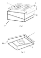
figures 3 and 4 show construction details of a preferred alternative embodiment of a portion of the system of the previous figures; -
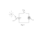
figure 5 show a control and power supply circuit of the portion shown infigures 3 and 4 . - In the figures the same reference numbers and letters identify the same elements or components.
- With reference to
figures 1 and 2 , the system according to the present invention provides the pneumatic connection between the filter housing F of the internal combustion engine and the battery compartment B of the vehicle. - The filter housing comprises an intake duct IN for sucking fresh air from the environment. Thus, according to the alternative embodiment shown in
figure 1 , the pneumatic connection is made by means of said intake duct IN.Figure 2 , instead, shows an alternative embodiment wherein the pneumatic connection is made directly between the filter housing F and the battery compartment B. - Such pneumatic connection, according to the shown alternative embodiments, is made by means of a tube-like duct C.
- Such duct is preferably connected to the battery compartment in an upper part of the latter, in order to collect the hot air accumulating under the lid.
- Advantageously, in a lot of industrial vehicles, the filter housing is arranged outside the cabin and in its lower part. Thus the filter housing and the battery compartment are often adjacent. Thus the modification to be implemented on the vehicles known in the art is limited, with ducts C being just a few centimetres long.
- According to another aspect of the invention, the cross section of the duct C is such that the flow rate of the air sucked from the battery compartment is limited to a small percentage of the whole fresh air sucked by the internal combustion engine. According to a preferred embodiment, such percentage is lower than 30% of the whole fresh air. According to a further preferred alternative embodiment, such percentage is 5-10%. The latter percentage is preferable, since it ensures a sufficient change of air in the battery compartment, without overheating the air sucked by the engine, representing the best possible trade-off in relation to the tests performed.
- Along the duct C, automatic means for closing the duct C itself may be provided, not shown, in case of detection of water in the duct C itself or in the battery compartment. As an alternative, water stopping means may be provided, such as filters, bends, etc.. These means are advantageous, in order to prevent the water to reach the internal combustion engine. Black arrows shown in the figures indicate the direction of movement of the intake air of the internal combustion engine. According to a further alternative embodiment of the invention, the battery compartment comprises a window O, possibly provided with a grille in order to facilitate the intake of fresh air in the compartment itself.
- The solution described so far may be adopted also in cars and in any other vehicle motorized with internal combustion engines.
- According to a further alternative embodiment of the invention, the lid B1 of the battery compartment, suitable to upperly close/define the compartment itself, according to a reciprocally complementary coupling, is equipped with a system for introducing air within the battery compartment B. Such additional ventilation system, that may be integrated in the lid B1, comprises, with reference to
figures 3 and 4 - an
electric fan 4 associated to the lid B1, - the lid B1 comprises a through opening (not shown) which allows the
electric fan 4 to introduce/suck fresh air of the environment within the battery compartment B, - a
protection 1 is fixed to cover, at least partially, the lid 5, in order to screen it from the sun radiation R, as shown infigure 5 , - a
photovoltaic generator 3 fixed on said protection (1) or defining theprotection 1 and electrically connected to theelectric fan 4 to feed it, - a thermostat T is arranged inside the compartment B in order to activate the
electric fan 4 when the internal temperature exceeds a predetermined threshold. - When the vehicle is at a standstill, the additional ventilation system provides for the ventilation of the battery compartment B. When the internal combustion engine is working, the two systems may cooperate, the
fan 4 introducing air in the compartment B and the internal combustion engine sucking it at the same time. - According to a preferred embodiment of the invention, the
fan 4 sucks air from the battery compartment. According to another preferred embodiment of the invention, thefan 4 sucks air from the battery compartment until the vehicle engine is stopped. - If the thermostat T is not present, the
electric fan 4 works independently of the temperature in the battery compartment and/or the operating state of the engine. - Being the
cover 1 superimposed to the outlet of the electric fan, the functioning of the electric fan tends to reduce also the temperature of thephotovoltaic generator 3 which improves its efficiency. - Moreover, the arrangement of the
cover 1 on the lid B1 advantageously protects the compartment itself from the direct radiation R and protects mechanically theelectric fan 4. - Advantageously, in the alternative embodiment wherein the whole additional ventilation system is integrated in the lid, it is evident that such lid may replace a pre-existing lid without any modification, both as an optional device that can be used at the discretion of the vehicle driver, and as a device used before the delivery and selling of the vehicle. Advantageously, such lid is electrically autonomous, at least until it is not directly exposed to the sun radiation. If it is necessary for device to operate also when it is not directly exposed to the sun radiation, thin-film solar cells may be used, which ensure a good performance, also when exposed to diffused sun radiation.
- It will be apparent to the person skilled in the art that other alternative and equivalent embodiments of the invention can be conceived and reduced to practice without departing from the scope of the invention.
- From the description set forth above it will be possible for the person skilled in the art to embody the invention with no need of describing further construction details. The elements and the characteristics described in the different preferred embodiments may be combined without departing from the scope of the present application.
Claims (13)
- Ventilation system of a battery compartment (B) of a vehicle, the vehicle comprising an internal combustion engine and a filter housing (F) for filtering fresh air sucked by the internal combustion engine, the system comprising a pneumatic connection (C) connecting the battery compartment (B) with said filter housing (F).
- System according to claim 1, wherein said filter housing (F) further comprises a fresh air intake duct (IN) and wherein said pneumatic connection is made through said fresh air intake duct (IN).
- System according to claim 1, wherein said pneumatic connection is made directly between said battery compartment (B) and said filter housing (F).
- System according to any of the previous claims, wherein said pneumatic connection (C) comprises automatic closing means of the pneumatic connection (C) itself, in order to avoid entering of water into the intake of the internal combustion engine of the vehicle.
- System according to claim 4, wherein said automatic closing means are suitable to activate when the presence of water is detected in the pneumatic connection (C) itself and/or in the battery compartment.
- System according to any of the previous claims, wherein said pneumatic connection (C) comprises water stopping means, in order to avoid entering of water in the intake of the internal combustion engine of the vehicle.
- System according to any of the previous claims, further comprising an electric fan (4) for introducing/extracting fresh air in/from the battery compartment (B)
- System according to claim 7, wherein a lid (B1) of said battery compartment comprises- said electric fan (4),- a through opening which allows the electric fan (4) to introduce fresh air of the environment within the battery compartment (B).
- System according to claim 8, wherein said lid (B1) further comprises- a protection (1) fixed to cover at least partially the lid (B1), in order to screen it from the sun radiation (R),- a photovoltaic generator (3) fixed on said protection (1) or defining the protection (1) and electrically connected to the electric fan (4) to feed it,- an optional thermostat T arranged within the compartment (B) for activating the electric fan (4) only when the internal temperature exceeds a predetermined threshold.
- Filter housing (F) comprising an additional opening or having an intake duct (IN) comprising an additional opening for the pneumatic connection (C) to a vehicle battery compartment.
- Battery (B) comprising an additional opening for the pneumatic connection (C) to a filter housing (F) for filtering the fresh air to be introduced in an internal combustion engine.
- Ground vehicle comprising the ventilation system according to any one of the previous claims from 1 to 9.
- Ground vehicle according to claim 12, of the industrial type having a cabin (Cab) and a filter housing (F) placed externally and in the rear of the cabin and a battery compartment arranged in a position adjacent to the filter housing (F).
Priority Applications (2)
| Application Number | Priority Date | Filing Date | Title |
|---|---|---|---|
| ES12190528.5T ES2617064T3 (en) | 2012-10-30 | 2012-10-30 | Ventilation system of a battery compartment of a vehicle, especially an industrial vehicle |
| EP12190528.5A EP2728661B1 (en) | 2012-10-30 | 2012-10-30 | System for the ventilation of a vehicle battery compartment especially of an industrial vehicle |
Applications Claiming Priority (1)
| Application Number | Priority Date | Filing Date | Title |
|---|---|---|---|
| EP12190528.5A EP2728661B1 (en) | 2012-10-30 | 2012-10-30 | System for the ventilation of a vehicle battery compartment especially of an industrial vehicle |
Publications (2)
| Publication Number | Publication Date |
|---|---|
| EP2728661A1 true EP2728661A1 (en) | 2014-05-07 |
| EP2728661B1 EP2728661B1 (en) | 2016-12-07 |
Family
ID=47561055
Family Applications (1)
| Application Number | Title | Priority Date | Filing Date |
|---|---|---|---|
| EP12190528.5A Active EP2728661B1 (en) | 2012-10-30 | 2012-10-30 | System for the ventilation of a vehicle battery compartment especially of an industrial vehicle |
Country Status (2)
| Country | Link |
|---|---|
| EP (1) | EP2728661B1 (en) |
| ES (1) | ES2617064T3 (en) |
Cited By (3)
| Publication number | Priority date | Publication date | Assignee | Title |
|---|---|---|---|---|
| EP3339072A1 (en) * | 2016-12-22 | 2018-06-27 | Volvo Car Corporation | Air intake system |
| EP3425124A4 (en) * | 2016-02-29 | 2019-11-20 | Yanmar Co., Ltd. | CONSTRUCTION MACHINE |
| CN114171820A (en) * | 2021-11-26 | 2022-03-11 | 山化中科(东营)石油科技有限公司 | Battery energy storage mutual feedback equipment and use method thereof |
Citations (10)
| Publication number | Priority date | Publication date | Assignee | Title |
|---|---|---|---|---|
| DE3736777C1 (en) * | 1987-10-30 | 1988-12-15 | Daimler Benz Ag | Device for avoiding the ingress of water into an air filter housing |
| US4976327A (en) * | 1989-02-14 | 1990-12-11 | Globe-Union Inc. | Battery module for the engine compartment of an automobile |
| US5542489A (en) * | 1995-05-31 | 1996-08-06 | Ford Motor Company | Battery thermal chamber |
| DE19725336A1 (en) * | 1997-06-16 | 1998-12-17 | Bayerische Motoren Werke Ag | Cooling system for battery of motor vehicle provided with IC engine |
| DE19730188A1 (en) * | 1997-07-15 | 1999-01-21 | Opel Adam Ag | Water leakage prevention device for air filter housing of IC engine |
| EP1013512A2 (en) * | 1998-12-23 | 2000-06-28 | Illbruck GmbH | Battery cover |
| US6564768B2 (en) * | 2000-10-26 | 2003-05-20 | Filterwerk Mann & Hummel Gmbh | Air intake system for an internal combustion engine |
| US20030226653A1 (en) * | 2002-06-10 | 2003-12-11 | Honda Giken Kogyo Kabushiki Kaisha | Structure for cooling high-voltage built-in units in hybrid vehicle |
| US20110183599A1 (en) * | 2010-01-26 | 2011-07-28 | Channell Commercial Corporation | Uninteruptable power supply enclosure and battery locker |
| DE102011006648A1 (en) * | 2011-04-01 | 2012-10-04 | Continental Automotive Gmbh | Energy storage device with a solar cell module and associated operating method |
Family Cites Families (1)
| Publication number | Priority date | Publication date | Assignee | Title |
|---|---|---|---|---|
| JP2006001489A (en) * | 2004-06-21 | 2006-01-05 | Toyota Motor Corp | Power cooling mechanism for hybrid power output device |
-
2012
- 2012-10-30 ES ES12190528.5T patent/ES2617064T3/en active Active
- 2012-10-30 EP EP12190528.5A patent/EP2728661B1/en active Active
Patent Citations (10)
| Publication number | Priority date | Publication date | Assignee | Title |
|---|---|---|---|---|
| DE3736777C1 (en) * | 1987-10-30 | 1988-12-15 | Daimler Benz Ag | Device for avoiding the ingress of water into an air filter housing |
| US4976327A (en) * | 1989-02-14 | 1990-12-11 | Globe-Union Inc. | Battery module for the engine compartment of an automobile |
| US5542489A (en) * | 1995-05-31 | 1996-08-06 | Ford Motor Company | Battery thermal chamber |
| DE19725336A1 (en) * | 1997-06-16 | 1998-12-17 | Bayerische Motoren Werke Ag | Cooling system for battery of motor vehicle provided with IC engine |
| DE19730188A1 (en) * | 1997-07-15 | 1999-01-21 | Opel Adam Ag | Water leakage prevention device for air filter housing of IC engine |
| EP1013512A2 (en) * | 1998-12-23 | 2000-06-28 | Illbruck GmbH | Battery cover |
| US6564768B2 (en) * | 2000-10-26 | 2003-05-20 | Filterwerk Mann & Hummel Gmbh | Air intake system for an internal combustion engine |
| US20030226653A1 (en) * | 2002-06-10 | 2003-12-11 | Honda Giken Kogyo Kabushiki Kaisha | Structure for cooling high-voltage built-in units in hybrid vehicle |
| US20110183599A1 (en) * | 2010-01-26 | 2011-07-28 | Channell Commercial Corporation | Uninteruptable power supply enclosure and battery locker |
| DE102011006648A1 (en) * | 2011-04-01 | 2012-10-04 | Continental Automotive Gmbh | Energy storage device with a solar cell module and associated operating method |
Cited By (4)
| Publication number | Priority date | Publication date | Assignee | Title |
|---|---|---|---|---|
| EP3425124A4 (en) * | 2016-02-29 | 2019-11-20 | Yanmar Co., Ltd. | CONSTRUCTION MACHINE |
| EP3339072A1 (en) * | 2016-12-22 | 2018-06-27 | Volvo Car Corporation | Air intake system |
| CN114171820A (en) * | 2021-11-26 | 2022-03-11 | 山化中科(东营)石油科技有限公司 | Battery energy storage mutual feedback equipment and use method thereof |
| CN114171820B (en) * | 2021-11-26 | 2023-12-05 | 碳谷(山东)能源科技集团有限公司 | Battery energy storage mutual feeding equipment and use method thereof |
Also Published As
| Publication number | Publication date |
|---|---|
| ES2617064T3 (en) | 2017-06-15 |
| EP2728661B1 (en) | 2016-12-07 |
Similar Documents
| Publication | Publication Date | Title |
|---|---|---|
| JP6107929B2 (en) | Temperature control structure | |
| CN103568820B (en) | The battery bag cooling structure of electric vehicle | |
| JP5272610B2 (en) | In-vehicle battery device | |
| US9306251B2 (en) | Battery pack | |
| CN102844214B (en) | Vehicle battery cooling system | |
| CN103579545B (en) | For the power brick of vehicle | |
| JP6780343B2 (en) | Battery cooling device | |
| JP2013249039A (en) | Cooling mechanism for battery pack of hybrid vehicle | |
| US9308484B1 (en) | Environmental air filter system | |
| CN104412446A (en) | Temperature regulation system and method for estimating foreign matter clogging amount | |
| US20160141572A1 (en) | Liquid trap for a lithium ion battery system | |
| EP2728661B1 (en) | System for the ventilation of a vehicle battery compartment especially of an industrial vehicle | |
| CN102442202A (en) | Vehicle charger and battery cooling structure | |
| JP6400464B2 (en) | Battery device | |
| US10107189B2 (en) | Package-storage type engine generator | |
| US10227919B2 (en) | Package-storage type engine generator | |
| JP2013206728A (en) | Cooling structure of battery pack for vehicle | |
| EP2605307B1 (en) | System for extracting air from a battery compartment of an industrial vehicle | |
| JP2013173469A (en) | Cooling structure for vehicle battery case | |
| JP2015012628A (en) | Cooling system | |
| WO2017149979A1 (en) | Construction machine | |
| CN113727873A (en) | Vehicle rechargeable battery with housing pre-installed with interface | |
| JP4631555B2 (en) | Cooling structure for electrical equipment | |
| JP2009154823A (en) | Auxiliary machine unit for vehicle | |
| KR101000692B1 (en) | Intake duct structure for cooling and warming of automotive electrical parts |
Legal Events
| Date | Code | Title | Description |
|---|---|---|---|
| PUAI | Public reference made under article 153(3) epc to a published international application that has entered the european phase |
Free format text: ORIGINAL CODE: 0009012 |
|
| 17P | Request for examination filed |
Effective date: 20121030 |
|
| AK | Designated contracting states |
Kind code of ref document: A1 Designated state(s): AL AT BE BG CH CY CZ DE DK EE ES FI FR GB GR HR HU IE IS IT LI LT LU LV MC MK MT NL NO PL PT RO RS SE SI SK SM TR |
|
| AX | Request for extension of the european patent |
Extension state: BA ME |
|
| 17P | Request for examination filed |
Effective date: 20141106 |
|
| RBV | Designated contracting states (corrected) |
Designated state(s): AL AT BE BG CH CY CZ DE DK EE ES FI FR GB GR HR HU IE IS IT LI LT LU LV MC MK MT NL NO PL PT RO RS SE SI SK SM TR |
|
| 17Q | First examination report despatched |
Effective date: 20160307 |
|
| REG | Reference to a national code |
Ref country code: DE Ref legal event code: R079 Ref document number: 602012026256 Country of ref document: DE Free format text: PREVIOUS MAIN CLASS: H01M0010625000 Ipc: B60H0001000000 |
|
| GRAP | Despatch of communication of intention to grant a patent |
Free format text: ORIGINAL CODE: EPIDOSNIGR1 |
|
| RIC1 | Information provided on ipc code assigned before grant |
Ipc: B60K 1/00 20060101ALN20160531BHEP Ipc: B60H 1/00 20060101AFI20160531BHEP Ipc: H01M 10/625 20140101ALI20160531BHEP Ipc: F02M 35/16 20060101ALI20160531BHEP Ipc: F02M 35/10 20060101ALI20160531BHEP Ipc: B60K 1/04 20060101ALI20160531BHEP Ipc: H01M 2/10 20060101ALI20160531BHEP Ipc: H01M 10/6563 20140101ALI20160531BHEP Ipc: H01M 10/663 20140101ALI20160531BHEP Ipc: B60R 16/04 20060101ALI20160531BHEP Ipc: F02M 35/08 20060101ALI20160531BHEP Ipc: F02M 35/108 20060101ALI20160531BHEP Ipc: B60K 13/02 20060101ALN20160531BHEP |
|
| INTG | Intention to grant announced |
Effective date: 20160624 |
|
| RIC1 | Information provided on ipc code assigned before grant |
Ipc: B60R 16/04 20060101ALI20160616BHEP Ipc: F02M 35/16 20060101ALI20160616BHEP Ipc: B60H 1/00 20060101AFI20160616BHEP Ipc: B60K 1/04 20060101ALI20160616BHEP Ipc: F02M 35/08 20060101ALI20160616BHEP Ipc: H01M 10/6563 20140101ALI20160616BHEP Ipc: F02M 35/108 20060101ALI20160616BHEP Ipc: F02M 35/10 20060101ALI20160616BHEP Ipc: B60K 1/00 20060101ALN20160616BHEP Ipc: H01M 10/663 20140101ALI20160616BHEP Ipc: H01M 2/10 20060101ALI20160616BHEP Ipc: H01M 10/625 20140101ALI20160616BHEP Ipc: B60K 13/02 20060101ALN20160616BHEP |
|
| GRAS | Grant fee paid |
Free format text: ORIGINAL CODE: EPIDOSNIGR3 |
|
| GRAA | (expected) grant |
Free format text: ORIGINAL CODE: 0009210 |
|
| AK | Designated contracting states |
Kind code of ref document: B1 Designated state(s): AL AT BE BG CH CY CZ DE DK EE ES FI FR GB GR HR HU IE IS IT LI LT LU LV MC MK MT NL NO PL PT RO RS SE SI SK SM TR |
|
| REG | Reference to a national code |
Ref country code: GB Ref legal event code: FG4D |
|
| REG | Reference to a national code |
Ref country code: CH Ref legal event code: EP Ref country code: AT Ref legal event code: REF Ref document number: 851374 Country of ref document: AT Kind code of ref document: T Effective date: 20161215 |
|
| REG | Reference to a national code |
Ref country code: IE Ref legal event code: FG4D |
|
| REG | Reference to a national code |
Ref country code: DE Ref legal event code: R096 Ref document number: 602012026256 Country of ref document: DE |
|
| REG | Reference to a national code |
Ref country code: CH Ref legal event code: NV Representative=s name: RENTSCH PARTNER AG, CH |
|
| REG | Reference to a national code |
Ref country code: NL Ref legal event code: FP |
|
| PG25 | Lapsed in a contracting state [announced via postgrant information from national office to epo] |
Ref country code: LV Free format text: LAPSE BECAUSE OF FAILURE TO SUBMIT A TRANSLATION OF THE DESCRIPTION OR TO PAY THE FEE WITHIN THE PRESCRIBED TIME-LIMIT Effective date: 20161207 |
|
| REG | Reference to a national code |
Ref country code: SE Ref legal event code: TRGR |
|
| REG | Reference to a national code |
Ref country code: LT Ref legal event code: MG4D |
|
| PG25 | Lapsed in a contracting state [announced via postgrant information from national office to epo] |
Ref country code: NO Free format text: LAPSE BECAUSE OF FAILURE TO SUBMIT A TRANSLATION OF THE DESCRIPTION OR TO PAY THE FEE WITHIN THE PRESCRIBED TIME-LIMIT Effective date: 20170307 Ref country code: GR Free format text: LAPSE BECAUSE OF FAILURE TO SUBMIT A TRANSLATION OF THE DESCRIPTION OR TO PAY THE FEE WITHIN THE PRESCRIBED TIME-LIMIT Effective date: 20170308 Ref country code: LT Free format text: LAPSE BECAUSE OF FAILURE TO SUBMIT A TRANSLATION OF THE DESCRIPTION OR TO PAY THE FEE WITHIN THE PRESCRIBED TIME-LIMIT Effective date: 20161207 |
|
| REG | Reference to a national code |
Ref country code: AT Ref legal event code: MK05 Ref document number: 851374 Country of ref document: AT Kind code of ref document: T Effective date: 20161207 |
|
| PG25 | Lapsed in a contracting state [announced via postgrant information from national office to epo] |
Ref country code: HR Free format text: LAPSE BECAUSE OF FAILURE TO SUBMIT A TRANSLATION OF THE DESCRIPTION OR TO PAY THE FEE WITHIN THE PRESCRIBED TIME-LIMIT Effective date: 20161207 Ref country code: RS Free format text: LAPSE BECAUSE OF FAILURE TO SUBMIT A TRANSLATION OF THE DESCRIPTION OR TO PAY THE FEE WITHIN THE PRESCRIBED TIME-LIMIT Effective date: 20161207 Ref country code: FI Free format text: LAPSE BECAUSE OF FAILURE TO SUBMIT A TRANSLATION OF THE DESCRIPTION OR TO PAY THE FEE WITHIN THE PRESCRIBED TIME-LIMIT Effective date: 20161207 |
|
| REG | Reference to a national code |
Ref country code: ES Ref legal event code: FG2A Ref document number: 2617064 Country of ref document: ES Kind code of ref document: T3 Effective date: 20170615 |
|
| PG25 | Lapsed in a contracting state [announced via postgrant information from national office to epo] |
Ref country code: IS Free format text: LAPSE BECAUSE OF FAILURE TO SUBMIT A TRANSLATION OF THE DESCRIPTION OR TO PAY THE FEE WITHIN THE PRESCRIBED TIME-LIMIT Effective date: 20170407 Ref country code: EE Free format text: LAPSE BECAUSE OF FAILURE TO SUBMIT A TRANSLATION OF THE DESCRIPTION OR TO PAY THE FEE WITHIN THE PRESCRIBED TIME-LIMIT Effective date: 20161207 Ref country code: SK Free format text: LAPSE BECAUSE OF FAILURE TO SUBMIT A TRANSLATION OF THE DESCRIPTION OR TO PAY THE FEE WITHIN THE PRESCRIBED TIME-LIMIT Effective date: 20161207 Ref country code: CZ Free format text: LAPSE BECAUSE OF FAILURE TO SUBMIT A TRANSLATION OF THE DESCRIPTION OR TO PAY THE FEE WITHIN THE PRESCRIBED TIME-LIMIT Effective date: 20161207 Ref country code: RO Free format text: LAPSE BECAUSE OF FAILURE TO SUBMIT A TRANSLATION OF THE DESCRIPTION OR TO PAY THE FEE WITHIN THE PRESCRIBED TIME-LIMIT Effective date: 20161207 |
|
| PG25 | Lapsed in a contracting state [announced via postgrant information from national office to epo] |
Ref country code: AT Free format text: LAPSE BECAUSE OF FAILURE TO SUBMIT A TRANSLATION OF THE DESCRIPTION OR TO PAY THE FEE WITHIN THE PRESCRIBED TIME-LIMIT Effective date: 20161207 Ref country code: SM Free format text: LAPSE BECAUSE OF FAILURE TO SUBMIT A TRANSLATION OF THE DESCRIPTION OR TO PAY THE FEE WITHIN THE PRESCRIBED TIME-LIMIT Effective date: 20161207 Ref country code: PT Free format text: LAPSE BECAUSE OF FAILURE TO SUBMIT A TRANSLATION OF THE DESCRIPTION OR TO PAY THE FEE WITHIN THE PRESCRIBED TIME-LIMIT Effective date: 20170407 Ref country code: PL Free format text: LAPSE BECAUSE OF FAILURE TO SUBMIT A TRANSLATION OF THE DESCRIPTION OR TO PAY THE FEE WITHIN THE PRESCRIBED TIME-LIMIT Effective date: 20161207 Ref country code: BE Free format text: LAPSE BECAUSE OF FAILURE TO SUBMIT A TRANSLATION OF THE DESCRIPTION OR TO PAY THE FEE WITHIN THE PRESCRIBED TIME-LIMIT Effective date: 20161207 Ref country code: BG Free format text: LAPSE BECAUSE OF FAILURE TO SUBMIT A TRANSLATION OF THE DESCRIPTION OR TO PAY THE FEE WITHIN THE PRESCRIBED TIME-LIMIT Effective date: 20170307 |
|
| REG | Reference to a national code |
Ref country code: DE Ref legal event code: R097 Ref document number: 602012026256 Country of ref document: DE |
|
| REG | Reference to a national code |
Ref country code: FR Ref legal event code: PLFP Year of fee payment: 6 |
|
| REG | Reference to a national code |
Ref country code: CH Ref legal event code: PCAR Free format text: NEW ADDRESS: BELLERIVESTRASSE 203 POSTFACH, 8034 ZUERICH (CH) |
|
| PLBE | No opposition filed within time limit |
Free format text: ORIGINAL CODE: 0009261 |
|
| STAA | Information on the status of an ep patent application or granted ep patent |
Free format text: STATUS: NO OPPOSITION FILED WITHIN TIME LIMIT |
|
| 26N | No opposition filed |
Effective date: 20170908 |
|
| PG25 | Lapsed in a contracting state [announced via postgrant information from national office to epo] |
Ref country code: DK Free format text: LAPSE BECAUSE OF FAILURE TO SUBMIT A TRANSLATION OF THE DESCRIPTION OR TO PAY THE FEE WITHIN THE PRESCRIBED TIME-LIMIT Effective date: 20161207 Ref country code: SI Free format text: LAPSE BECAUSE OF FAILURE TO SUBMIT A TRANSLATION OF THE DESCRIPTION OR TO PAY THE FEE WITHIN THE PRESCRIBED TIME-LIMIT Effective date: 20161207 |
|
| PG25 | Lapsed in a contracting state [announced via postgrant information from national office to epo] |
Ref country code: MC Free format text: LAPSE BECAUSE OF FAILURE TO SUBMIT A TRANSLATION OF THE DESCRIPTION OR TO PAY THE FEE WITHIN THE PRESCRIBED TIME-LIMIT Effective date: 20161207 |
|
| REG | Reference to a national code |
Ref country code: IE Ref legal event code: MM4A |
|
| PG25 | Lapsed in a contracting state [announced via postgrant information from national office to epo] |
Ref country code: LU Free format text: LAPSE BECAUSE OF NON-PAYMENT OF DUE FEES Effective date: 20171030 |
|
| PG25 | Lapsed in a contracting state [announced via postgrant information from national office to epo] |
Ref country code: MT Free format text: LAPSE BECAUSE OF NON-PAYMENT OF DUE FEES Effective date: 20171030 |
|
| REG | Reference to a national code |
Ref country code: FR Ref legal event code: PLFP Year of fee payment: 7 |
|
| PG25 | Lapsed in a contracting state [announced via postgrant information from national office to epo] |
Ref country code: IE Free format text: LAPSE BECAUSE OF NON-PAYMENT OF DUE FEES Effective date: 20171030 |
|
| PG25 | Lapsed in a contracting state [announced via postgrant information from national office to epo] |
Ref country code: HU Free format text: LAPSE BECAUSE OF FAILURE TO SUBMIT A TRANSLATION OF THE DESCRIPTION OR TO PAY THE FEE WITHIN THE PRESCRIBED TIME-LIMIT; INVALID AB INITIO Effective date: 20121030 |
|
| PG25 | Lapsed in a contracting state [announced via postgrant information from national office to epo] |
Ref country code: CY Free format text: LAPSE BECAUSE OF NON-PAYMENT OF DUE FEES Effective date: 20161207 |
|
| PG25 | Lapsed in a contracting state [announced via postgrant information from national office to epo] |
Ref country code: MK Free format text: LAPSE BECAUSE OF FAILURE TO SUBMIT A TRANSLATION OF THE DESCRIPTION OR TO PAY THE FEE WITHIN THE PRESCRIBED TIME-LIMIT Effective date: 20161207 |
|
| PG25 | Lapsed in a contracting state [announced via postgrant information from national office to epo] |
Ref country code: TR Free format text: LAPSE BECAUSE OF FAILURE TO SUBMIT A TRANSLATION OF THE DESCRIPTION OR TO PAY THE FEE WITHIN THE PRESCRIBED TIME-LIMIT Effective date: 20161207 |
|
| PG25 | Lapsed in a contracting state [announced via postgrant information from national office to epo] |
Ref country code: AL Free format text: LAPSE BECAUSE OF FAILURE TO SUBMIT A TRANSLATION OF THE DESCRIPTION OR TO PAY THE FEE WITHIN THE PRESCRIBED TIME-LIMIT Effective date: 20161207 |
|
| P01 | Opt-out of the competence of the unified patent court (upc) registered |
Effective date: 20230523 |
|
| REG | Reference to a national code |
Ref country code: CH Ref legal event code: U11 Free format text: ST27 STATUS EVENT CODE: U-0-0-U10-U11 (AS PROVIDED BY THE NATIONAL OFFICE) Effective date: 20251101 |
|
| PGFP | Annual fee paid to national office [announced via postgrant information from national office to epo] |
Ref country code: NL Payment date: 20251024 Year of fee payment: 14 |
|
| PGFP | Annual fee paid to national office [announced via postgrant information from national office to epo] |
Ref country code: DE Payment date: 20251028 Year of fee payment: 14 |
|
| PGFP | Annual fee paid to national office [announced via postgrant information from national office to epo] |
Ref country code: GB Payment date: 20251017 Year of fee payment: 14 |
|
| PGFP | Annual fee paid to national office [announced via postgrant information from national office to epo] |
Ref country code: IT Payment date: 20251009 Year of fee payment: 14 |
|
| PGFP | Annual fee paid to national office [announced via postgrant information from national office to epo] |
Ref country code: FR Payment date: 20251027 Year of fee payment: 14 |
|
| PGFP | Annual fee paid to national office [announced via postgrant information from national office to epo] |
Ref country code: SE Payment date: 20251024 Year of fee payment: 14 Ref country code: CH Payment date: 20251101 Year of fee payment: 14 |
|
| PGFP | Annual fee paid to national office [announced via postgrant information from national office to epo] |
Ref country code: ES Payment date: 20251118 Year of fee payment: 14 |