EP2728367B1 - A method for detecting a fault condition in an electrical machine - Google Patents
A method for detecting a fault condition in an electrical machine Download PDFInfo
- Publication number
- EP2728367B1 EP2728367B1 EP12190951.9A EP12190951A EP2728367B1 EP 2728367 B1 EP2728367 B1 EP 2728367B1 EP 12190951 A EP12190951 A EP 12190951A EP 2728367 B1 EP2728367 B1 EP 2728367B1
- Authority
- EP
- European Patent Office
- Prior art keywords
- frequency
- measurement
- frequency component
- circulating current
- current
- Prior art date
- Legal status (The legal status is an assumption and is not a legal conclusion. Google has not performed a legal analysis and makes no representation as to the accuracy of the status listed.)
- Active
Links
Images


Classifications
-
- G—PHYSICS
- G01—MEASURING; TESTING
- G01R—MEASURING ELECTRIC VARIABLES; MEASURING MAGNETIC VARIABLES
- G01R19/00—Arrangements for measuring currents or voltages or for indicating presence or sign thereof
- G01R19/02—Measuring effective values, i.e. root-mean-square values
-
- G—PHYSICS
- G01—MEASURING; TESTING
- G01R—MEASURING ELECTRIC VARIABLES; MEASURING MAGNETIC VARIABLES
- G01R23/00—Arrangements for measuring frequencies; Arrangements for analysing frequency spectra
-
- G—PHYSICS
- G01—MEASURING; TESTING
- G01R—MEASURING ELECTRIC VARIABLES; MEASURING MAGNETIC VARIABLES
- G01R31/00—Arrangements for testing electric properties; Arrangements for locating electric faults; Arrangements for electrical testing characterised by what is being tested not provided for elsewhere
- G01R31/34—Testing dynamo-electric machines
-
- G—PHYSICS
- G01—MEASURING; TESTING
- G01R—MEASURING ELECTRIC VARIABLES; MEASURING MAGNETIC VARIABLES
- G01R31/00—Arrangements for testing electric properties; Arrangements for locating electric faults; Arrangements for electrical testing characterised by what is being tested not provided for elsewhere
- G01R31/34—Testing dynamo-electric machines
- G01R31/343—Testing dynamo-electric machines in operation
-
- G—PHYSICS
- G01—MEASURING; TESTING
- G01R—MEASURING ELECTRIC VARIABLES; MEASURING MAGNETIC VARIABLES
- G01R31/00—Arrangements for testing electric properties; Arrangements for locating electric faults; Arrangements for electrical testing characterised by what is being tested not provided for elsewhere
- G01R31/34—Testing dynamo-electric machines
- G01R31/346—Testing of armature or field windings
Definitions
- the present invention relates to a method and a system for identifying a fault in an electrical machine.
- Detection of faults in electrical machines is an important issue for ensuring a reliable functioning of the machine. The earlier a fault is detected the better the maintenance can be planned thus avoiding uncontrolled machine stops and serious damages from occurring.
- Conventionally both mechanical and electrical characteristics of machines are used for identifying faults. For example, mechanical vibrations and the behavior of electrical currents within the machine have been used as fault indicators. Circulating currents between parallel connected winding branches have been found to be a good fault indicator since they are ideally equal to zero for a normal condition and increase due to any asymmetry within the machine. Circulating currents enable detection of faulty conditions at a very early stage, for example a crack of the rotor bars (before the bar is totally broken), inter-turn short-circuits, eccentricity problem, etc.
- GB2157005A discloses a spectrum analysis of circulating currents between two parallel winding branches in a stator of a two-pole alternator for detecting different types of faults. According to GB2157005A the relevant harmonics for analyzing the spectrum of the circulating currents are even harmonics of the supply frequency (50 Hz).
- US7253634B1 discloses detecting stator ground faults in a generator by analysing circulating currents. US7253634B1 discloses inter alia measuring the circulating currents in different electrical phases of the machine.
- MOHAMED EL HACHEMI BENBOUZID "A Review of Induction Motors Signature Analysis as a Medium for Faults Detection" discloses a fault detection method based on signature analysis in induction motors.
- One object of the present invention is to provide an improved method for detecting faults in electrical machines.
- a method for identifying a fault condition in an electrical machine in which at least a stator or a rotor has parallel winding branches comprising the steps of: carrying out a first measurement for obtaining a first set of circulating current values between two parallel winding branches of which each winding branch comprises a single coil; applying a frequency analysis on the first set of circulating current values to obtain at least one frequency component; and determining, on the basis of the at least one frequency component, a fault condition of the electrical machine.
- the fault condition is one of the following: dynamic eccentricity, static eccentricity, inter-turn short circuit in the rotor, inter-turn short circuit in the stator.
- the given fault conditions are those which are most common in electrical machines and which have the most practical significance, though it may be recognised by those skilled in the state of the art that the method may be used to diagnose other faults both in the electric machine and an associated load. In practice an electrical machine may suffer from a combination of the given fault conditions.
- the given frequencies have been found to be a strong indicator of dynamic eccentricity.
- the given frequencies have been found to be a strong indicator of static eccentricity.
- the given frequencies have been found to be a strong indicator of inter-turn short circuit in the rotor.
- the given frequencies have been found to be a strong indicator of inter-turn short circuit in the stator.
- the electrical machine is a synchronous electrical motor or generator.
- the present method is particularly effective in identifying fault conditions in synchronous electrical machines.
- the first measurement is carried out with two current sensors for obtaining branch current signals from the two parallel winding branches, and the first set of circulating current values is deduced from the branch current signals using an operational amplifier or using a numerical subtraction after the branch current signals have been converted into a digital domain.
- a measurement arrangement according to this provision can be relatively easily implemented even when the two winding branches are distant from each other.
- the first measurement is carried out with a differential current sensor.
- the measurement results are expected to be more accurate when a differential current sensor is used.
- the first measurement is carried out between two opposite winding branches in circumferential direction of the stator.
- the method comprises the step of carrying out a second measurement corresponding to the first measurement, the two parallel winding branches in the second measurement being different from those in the first measurement. This measure makes it possible to find out the fault position with respect to the stator.
- the two parallel winding branches in the second measurement are in a different electrical phase than those in the first measurement. This measure makes it possible to find out the fault position with respect to the stator in an improved way.
- the method comprises the step of carrying out a measurement corresponding to the first measurement for winding branches in each electrical phase of the electrical machine. This measure makes it possible to find out the fault position with respect to the stator in a further improved way.
- the fault condition of the electrical machine is determined on the basis of more than one frequency components.
- the method comprises the step of comparing an amplitude of the circulating current at the frequency component with a predetermined threshold value.
- a threshold value for a circulating current amplitude By implementing a threshold value for a circulating current amplitude, fault conditions can be distinguished from normal asymmetries of the machine.
- the first measurement is carried out during a transient operation of the electrical machine.
- Some fault condition related frequency components of the circulating current are prominent especially during a transient operation of the electrical machine. Analysing them contributes to an even stronger fault indication.
- a stator winding 10 of a three-phase and four-pole machine comprises four coils 20 for each electrical phase I, II, III.
- the coils 20 are connected in parallel in a winding arrangement comprising six winding branches 30, 40, 50, 60, 70, 80 wherein the first, second, third and fourth winding branches 30, 40, 50, 60 comprise a single coil 20, and the fifth and sixth winding branches 70, 80 comprise two coils 20 each.
- a coil 20 may consist of a plurality of serial connected coil sections i.e. in the context of the present invention a plurality of coil sections connected in series is equivalent with a single coil 20.
- circulating currents 85 are ideally zero when no faults are present in the machine, they are inherently well suited for identifying asymmetries and the corresponding fault conditions.
- a circulating current 85 is measured between a first and a second winding branch 30, 40 at a first electrical phase I. Both the first and the second winding branches 30, 40 comprise a single coil 20 in contrast to the fifth and sixth winding branches 70, 80 which each comprise two coils 20, as explained above.
- the circulating current 85 can be measured between the first and the third winding branches 30, 50, or between any other combination of two winding branches 30, 40, 50, 60 comprising a single coil 20 within the same electrical phase I, II, III. It is preferable to measure the circulating current 85 between two winding branches 30, 40, 50, 60 that only comprise a single coil 20 each.
- the circulating current 85 between such winding branches 30, 40, 50, 60 gives a better indication of a fault condition than the circulating current 85 between winding branches 70, 80 comprising more than one coil 20, even if the measurement can be more difficult to arrange in practice.
- the first arrangement comprises a first and a second branch current sensor 90, 100 arranged to measure the absolute currents at the respective winding branches 30, 40.
- the second arrangement comprises a differential sensor 110 arranged to measure the differential current between the two respective winding branches 30, 40.
- the circulating current values need to be deduced from the two measurements. This can be done by subtracting the output signals of the first and the second branch current sensors 90, 100 electrically e.g. with means of an operational amplifier, or numerically after the signals have been converted into a digital domain.
- the requirement to deduce the circulating current values from two measurements can be seen as a drawback, and another drawback with the first arrangement is that the measured absolute current values can be very high relative to the circulating current values of interest. The first arrangement is therefore more likely to suffer from noise than the second one.
- the differential sensor 110 of the second arrangement comprises a twisted sensor loop which surrounds the two winding branches 30, 40 in opposite directions such that the current induced in the twisted sensor loop directly corresponds to the circulating current 85.
- a drawback with the second arrangement is that in practice it can be difficult to arrange the differential measurement between two distant winding branches 30,...80 inside an electrical machine.
- the circulating current 85 should be measured between any combination of two winding branches 130, 140, 150, 160, 170, 180 selected from the six winding branches 130,...180 comprising a single coil 20 each, i.e. the seventh to the twelfth winding branches 130,...180.
- measuring the circulating current 85 between two opposite winding branches 130,...180 in circumferential direction of the stator 120, such as the seventh and the eighth winding branches 130, 140 in the embodiment of figure 2b results in an even stronger indication of a fault condition.
- circulating currents 85 are measured between two respective parallel winding branches 30, 40, 50, 60, 130, 140, 150, 160, 170, 180 at least at two different locations of the machine, it is possible to find out the fault position with respect to the stator 120. This can be done by extracting the spatial information by plotting one circulating current 85 against another, or by applying another technique that allows extracting the spatial information e.g. a space-frequency analysis. This is useful for example for detecting the direction of a static eccentricity.
- the different measurements are preferably carried out at least at two electrical phases I, II, III, such as at all electrical phases I, II, III of the machine.
- a differential sensor 110 gives directly the value of ( I 1 - I 2 ) while when using two separate branch current sensors 90, 100 this deduction needs to be carried out separately.
- the measurement finally results in a set of circulating current values. It is necessary to process these values such that relevant diagnostic information can be extracted.
- the frequency content of a circulating current 85 can be evaluated to identify fault conditions. Therefore, a frequency analysis is applied to the measurement results after transforming the results into frequency domain by the means of e.g. fast Fourier transform (FFT). Any other feasible mathematical or non-mathematical method enabling the observation of the measurement results in a frequency domain can be used, such as filtering out the non-interesting frequencies.
- FFT fast Fourier transform
- Any other feasible mathematical or non-mathematical method enabling the observation of the measurement results in a frequency domain can be used, such as filtering out the non-interesting frequencies.
- the measurement can be carried out during a steady state condition or during a transient operation (starting up or shutting down) of the electrical machine.
- any analysing technique requiring the use of frequency information such as Hilbert transform or wavelet decomposition, is considered as a frequency analysis 250.
- the amplitudes of these frequency components are compared with reference values known to be characteristic for certain fault conditions.
- the reference values can be obtained from computer simulation where different fault conditions are induced in a simulation model corresponding to the electrical machine of interest.
- the reference values can also be obtained from measurements on a real machine where a certain fault condition is intentionally induced or otherwise known.
- the reference values can be collected in a look-up table listing all known reference values and fault conditions they are associated with.
- a frequency component is recognized as an indication of a fault condition only if the circulating current amplitude at that frequency exceeds a certain threshold value.
- a frequency component with a small amplitude may occur at normal asymmetries of the machine, or it may be an indication of an approaching defect that has not yet evolved into a fault condition so severe that corrective measures need to be taken.
- the fault indicators can further be normalized in order to account for different electrical machines, regardless of their size and/or design.
- Fault_indicator is the relative amplitude which is to be compared with the threshold value
- RMS (I c ) is the root mean square of the circulating current at a given frequency component
- I rated is the rated current of the machine i.e. the current at full load of the machine
- a fault_related_frequency,i is an amplitude of the circulating current at the i th frequency component
- n is the number of frequency components
- a main is an amplitude of the main current at supply frequency.
- the relative amplitude which is to be compared with the threshold value is thus invariant to changes in operating conditions and may be easily compared against a scalar threshold value.
- the algorithm can also comprise a normalizing factor to account for different electrical machines, regardless of their size and/or design.
- the frequency signatures of figure 3 apply to a certain synchronous motor, and the results can be used to detect fault conditions in synchronous machines of the same type.
- the present method is not limited to the diagnosis of certain types of electrical machines, and it is especially not limited to diagnosis of synchronous machines.
- the present method can be applied to any electrical machine, such as an electrical motor or an electrical generator, in which at least the stator 120 or the rotor 220 has parallel winding branches 30,...60, 130,...180.
- the present method can be applied to induction machines.
- the present method can be used with circulating current values obtained from the rotor 220, although in practice it is easier to measure the circulating currents 85 from the stator 120.
- the present method comprises three major steps: a measurement 230 resulting in a set of circulating current values 240; a frequency analysis 250 resulting in at least one frequency component 260; and a fault condition identification 270 resulting in an eventual determination of a fault condition 280.
Landscapes
- Physics & Mathematics (AREA)
- General Physics & Mathematics (AREA)
- Tests Of Circuit Breakers, Generators, And Electric Motors (AREA)
Description
- The present invention relates to a method and a system for identifying a fault in an electrical machine.
- Detection of faults in electrical machines is an important issue for ensuring a reliable functioning of the machine. The earlier a fault is detected the better the maintenance can be planned thus avoiding uncontrolled machine stops and serious damages from occurring. Conventionally both mechanical and electrical characteristics of machines are used for identifying faults. For example, mechanical vibrations and the behavior of electrical currents within the machine have been used as fault indicators. Circulating currents between parallel connected winding branches have been found to be a good fault indicator since they are ideally equal to zero for a normal condition and increase due to any asymmetry within the machine. Circulating currents enable detection of faulty conditions at a very early stage, for example a crack of the rotor bars (before the bar is totally broken), inter-turn short-circuits, eccentricity problem, etc.
-
GB2157005A GB2157005A - WAN SHUTING et al: "A Compositive Diagnosis Method on Turbine-Generator Rotor Winding Inter-turn Short Circuit Fault" discloses detecting an inter-turn short circuit in a rotor by analysing circulating currents.
-
US7253634B1 discloses detecting stator ground faults in a generator by analysing circulating currents.US7253634B1 discloses inter alia measuring the circulating currents in different electrical phases of the machine. - MOHAMED EL HACHEMI BENBOUZID: "A Review of Induction Motors Signature Analysis as a Medium for Faults Detection" discloses a fault detection method based on signature analysis in induction motors.
- Though theoretically circulating currents provide an improved method of detecting machine faults at an early stage, there are a number of practical difficulties in realizing a method of acquiring and processing the relevant data. Such practical difficulties include finding the best fault indicators and learning to interpret the results correctly. A circulating current can be measured at many different locations of the machine, and arranging the measurement is difficult because the current sensors may need to be integrated into the windings of the machine. Therefore, this method is most appropriate for high power motors and generators, where there is sufficient room to locate the current sensors inside the machine. Furthermore, special skill is needed for interpreting the measurement results correctly in order to actually be able to detect a fault condition. There remains a desire to improve the existing fault detection methods in order to more reliably detect different types of faults.
- One object of the present invention is to provide an improved method for detecting faults in electrical machines.
- This object is achieved by the method according to appended
claim 1. - According to a first aspect of the invention, there is provided a method for identifying a fault condition in an electrical machine in which at least a stator or a rotor has parallel winding branches. The method comprising the steps of: carrying out a first measurement for obtaining a first set of circulating current values between two parallel winding branches of which each winding branch comprises a single coil; applying a frequency analysis on the first set of circulating current values to obtain at least one frequency component; and determining, on the basis of the at least one frequency component, a fault condition of the electrical machine.
- By measuring a circulating current between two parallel winding branches comprising a single coil, robust indicators of fault conditions in the machine can be obtained. Since the fault indicators are contained in the frequency spectrum of the circulating current, a frequency analysis is necessary for enabling the determination of the fault condition.
- According to one embodiment of the invention, the fault condition is one of the following: dynamic eccentricity, static eccentricity, inter-turn short circuit in the rotor, inter-turn short circuit in the stator. The given fault conditions are those which are most common in electrical machines and which have the most practical significance, though it may be recognised by those skilled in the state of the art that the method may be used to diagnose other faults both in the electric machine and an associated load. In practice an electrical machine may suffer from a combination of the given fault conditions.
- According to one embodiment of the invention, the method comprises the step of: determining, on the basis that the at least one frequency component has a value (2k + 1) fs ± fr, wherein k = (0,1,2,3,...), fs = supply frequency and fr = rotational frequency of the electrical machine, that the machine suffers from dynamic eccentricity. The given frequencies have been found to be a strong indicator of dynamic eccentricity.
- According to one embodiment of the invention, the method comprises the step of: determining, on the basis that the at least one frequency component has a value kfs, wherein k = (0,1,2,3,...) and fs = supply frequency, that the machine suffers from static eccentricity. The given frequencies have been found to be a strong indicator of static eccentricity.
- According to one embodiment of the invention, the method comprises the step of: determining, on the basis that the at least one frequency component has a value kfr, wherein k = (0,1,2,3,...) and fr = rotational frequency of the electrical machine, that the machine suffers from inter-turn short circuit in the rotor. The given frequencies have been found to be a strong indicator of inter-turn short circuit in the rotor.
- According to one embodiment of the invention, the method comprises the step of: determining, on the basis that the at least one frequency component has a value (2k + 1) fs , wherein k = (0,1,2,3,...) and fs = supply frequency, that the machine suffers from inter-turn short circuit in the stator. The given frequencies have been found to be a strong indicator of inter-turn short circuit in the stator.
- According to one embodiment of the invention, the electrical machine is a synchronous electrical motor or generator. The present method is particularly effective in identifying fault conditions in synchronous electrical machines.
- According to one embodiment of the invention, the first measurement is carried out with two current sensors for obtaining branch current signals from the two parallel winding branches, and the first set of circulating current values is deduced from the branch current signals using an operational amplifier or using a numerical subtraction after the branch current signals have been converted into a digital domain. A measurement arrangement according to this provision can be relatively easily implemented even when the two winding branches are distant from each other.
- According to one embodiment of the invention, the first measurement is carried out with a differential current sensor. The measurement results are expected to be more accurate when a differential current sensor is used.
- According to one embodiment of the invention, the first measurement is carried out between two opposite winding branches in circumferential direction of the stator. By this measure an even stronger fault indication is obtained.
- According to one embodiment of the invention, the method comprises the step of carrying out a second measurement corresponding to the first measurement, the two parallel winding branches in the second measurement being different from those in the first measurement. This measure makes it possible to find out the fault position with respect to the stator.
- According to one embodiment of the invention the two parallel winding branches in the second measurement are in a different electrical phase than those in the first measurement. This measure makes it possible to find out the fault position with respect to the stator in an improved way.
- According to one embodiment of the invention, the method comprises the step of carrying out a measurement corresponding to the first measurement for winding branches in each electrical phase of the electrical machine. This measure makes it possible to find out the fault position with respect to the stator in a further improved way.
- According to one embodiment of the invention, the fault condition of the electrical machine is determined on the basis of more than one frequency components. By this measure a higher certainty in indicating a fault condition is achieved.
- According to one embodiment of the invention, the method comprises the step of comparing an amplitude of the circulating current at the frequency component with a predetermined threshold value. By implementing a threshold value for a circulating current amplitude, fault conditions can be distinguished from normal asymmetries of the machine.
- According to one embodiment of the invention, the method comprises the step of: comparing a relative amplitude of the circulating current at the frequency component with a predetermined threshold value, wherein the relative amplitude is determined by an algorithm comprising a root mean square of the circulating current at the frequency component, by an algorithm comprising a
factor 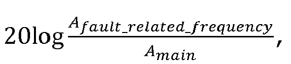

- According to one embodiment of the invention, the first measurement is carried out during a transient operation of the electrical machine. Some fault condition related frequency components of the circulating current are prominent especially during a transient operation of the electrical machine. Analysing them contributes to an even stronger fault indication.
- The invention will be explained in greater detail with reference to the accompanying drawings, wherein
- figure 1
- shows a measurement installation according to an embodiment of the invention,
- figure 2
- shows a measurement installation according to an embodiment of the invention,
- figure 3
- shows a look-up table for fault indication for the case of a synchronous motor, and
- figure 4
- shows a flow chart illustrating the major steps of the method according to the invention.
- Referring to
figure 1 , a stator winding 10 of a three-phase and four-pole machine comprises fourcoils 20 for each electrical phase I, II, III. Thecoils 20 are connected in parallel in a winding arrangement comprising six windingbranches branches single coil 20, and the fifth and sixth windingbranches coils 20 each. In practice, acoil 20 may consist of a plurality of serial connected coil sections i.e. in the context of the present invention a plurality of coil sections connected in series is equivalent with asingle coil 20. When the machine is operating, electric currents are flowing through the windingbranches 30,...80 in accordance to the characteristics and operating conditions of the machine. Since the windingbranches single coil 20 are connected in parallel at each electrical phase I, II, III, and since an ideal machine is symmetrical in structure, in theory the currents in all corresponding windingbranches branches coils 20 each. However, a real machine always has some asymmetry that causes the magnetic fluxes in thedifferent coils 20 and the resulting electromotive forces (EMF) resisting the currents to differ. As a consequence, the currents induced in thedifferent coils 20 also differ, and circulatingcurrents 85 between the parallel connected windingbranches 30,...80 occur. - As indicated above, a small asymmetry is normal for every electrical machine. However, in a faulty machine asymmetries increase together with the severity of the fault condition. It is therefore practical to observe asymmetries to identify fault conditions in electrical machines. Since circulating
currents 85 are ideally zero when no faults are present in the machine, they are inherently well suited for identifying asymmetries and the corresponding fault conditions. In the example offigure 1 a circulating current 85 is measured between a first and a second windingbranch branches single coil 20 in contrast to the fifth and sixth windingbranches coils 20, as explained above. Alternatively, in the example offigure 1 the circulating current 85 can be measured between the first and the third windingbranches branches single coil 20 within the same electrical phase I, II, III. It is preferable to measure the circulating current 85 between two windingbranches single coil 20 each. The circulating current 85 between such windingbranches branches coil 20, even if the measurement can be more difficult to arrange in practice. - In
figure 1 two possible measuring arrangements are shown. The first arrangement comprises a first and a secondbranch current sensor branches differential sensor 110 arranged to measure the differential current between the two respective windingbranches current sensors differential sensor 110 of the second arrangement comprises a twisted sensor loop which surrounds the two windingbranches branches 30,...80 inside an electrical machine. - Referring to
figures 2a and 2b , thecoils 20 for the first electrical phase I in a six-pole machine are distributed symmetrically about a circumference of astator 120. The machine may have three or more electrical phases I, II, III, but for the purpose of measuring circulatingcurrents 85 it is enough to consider only one electrical phase I, II, III at a time. At the first electrical phase I, there are seventh, eighth, ninth, tenth, eleventh and twelfth windingbranches single coil 20 each. In addition, there are thirteenth, fourteenth and fifteenth windingbranches coils 20 each. According to the description above, the circulating current 85 should be measured between any combination of two windingbranches branches 130,...180 comprising asingle coil 20 each, i.e. the seventh to the twelfth windingbranches 130,...180. However, measuring the circulating current 85 between two opposite windingbranches 130,...180 in circumferential direction of thestator 120, such as the seventh and the eighth windingbranches figure 2b , results in an even stronger indication of a fault condition. - If circulating
currents 85 are measured between two respective parallel windingbranches stator 120. This can be done by extracting the spatial information by plotting one circulating current 85 against another, or by applying another technique that allows extracting the spatial information e.g. a space-frequency analysis. This is useful for example for detecting the direction of a static eccentricity. The different measurements are preferably carried out at least at two electrical phases I, II, III, such as at all electrical phases I, II, III of the machine. - From a measurement of individual branch currents, the circulating current values can be extracted according to the equation

differential sensor 110 gives directly the value of (I 1-I 2) while when using two separate branchcurrent sensors - The measurement finally results in a set of circulating current values. It is necessary to process these values such that relevant diagnostic information can be extracted. The frequency content of a circulating current 85 can be evaluated to identify fault conditions. Therefore, a frequency analysis is applied to the measurement results after transforming the results into frequency domain by the means of e.g. fast Fourier transform (FFT). Any other feasible mathematical or non-mathematical method enabling the observation of the measurement results in a frequency domain can be used, such as filtering out the non-interesting frequencies. The measurement can be carried out during a steady state condition or during a transient operation (starting up or shutting down) of the electrical machine. In the context of the present invention any analysing technique requiring the use of frequency information, such as Hilbert transform or wavelet decomposition, is considered as a
frequency analysis 250. - From the frequency analysis of the circulating current a number of frequency components will be available. The amplitudes of these frequency components are compared with reference values known to be characteristic for certain fault conditions. The reference values can be obtained from computer simulation where different fault conditions are induced in a simulation model corresponding to the electrical machine of interest. The reference values can also be obtained from measurements on a real machine where a certain fault condition is intentionally induced or otherwise known. The reference values can be collected in a look-up table listing all known reference values and fault conditions they are associated with.
- Referring to
figure 3 , a look-up table for fault indication may comprise columns corresponding to different fault conditions and rows corresponding to certain reference frequencies. The frequency or frequencies associated with a certain fault condition are marked on the look-up table taking a dominance of the amplitude into account. For example, an existence of a frequency component with a value kfr, wherein k = (1,2,3,...) and fr = rotational frequency of the electrical machine, indicates that the machine suffers from inter-turn short circuit in therotor 220. Although in a healthy machine the circulating current amplitudes at the given frequencies are close to zero, an existence of a certain frequency component as such does not necessarily mean that there is a fault condition. The appearance of a frequency component is recognized as an indication of a fault condition only if the circulating current amplitude at that frequency exceeds a certain threshold value. A frequency component with a small amplitude may occur at normal asymmetries of the machine, or it may be an indication of an approaching defect that has not yet evolved into a fault condition so severe that corrective measures need to be taken. The fault indicators can further be normalized in order to account for different electrical machines, regardless of their size and/or design. - When determining a threshold value for an amplitude of the circulating current at a frequency component, above which the oscillation shall be recognized as an indication of a fault condition, differences between circulating current amplitudes caused by changes in operating conditions mean that it is not necessarily feasible to determine a threshold value in terms of an absolute amplitude value. Instead, it has been found to be more feasible to determine a relative circulating current amplitude according to an algorithm

- The frequency signatures of
figure 3 apply to a certain synchronous motor, and the results can be used to detect fault conditions in synchronous machines of the same type. However, the present method is not limited to the diagnosis of certain types of electrical machines, and it is especially not limited to diagnosis of synchronous machines. On the contrary, the present method can be applied to any electrical machine, such as an electrical motor or an electrical generator, in which at least thestator 120 or therotor 220 has parallel windingbranches 30,...60, 130,...180. Especially, the present method can be applied to induction machines. The present method can be used with circulating current values obtained from therotor 220, although in practice it is easier to measure the circulatingcurrents 85 from thestator 120. - Referring to
figure 4 , the present method comprises three major steps: ameasurement 230 resulting in a set of circulatingcurrent values 240; afrequency analysis 250 resulting in at least onefrequency component 260; and afault condition identification 270 resulting in an eventual determination of afault condition 280. - The invention is not limited to the embodiments shown above, but a person skilled in the art may modify them in a plurality of ways within the scope of the invention as defined by the claims.
Claims (14)
- A method for identifying a fault condition in an electrical machine in which at least a stator (120) or a rotor (220) has electrically parallel winding branches (30, 40, 50, 60, 130, 140, 150, 160, 170, 180), the method comprising the steps of:- carrying out a first measurement (230) for obtaining a first set of circulating current values (240) between two electrically parallel winding branches (30, 40, 50, 60, 130, 140, 150, 160, 170, 180) of which each winding branch (30, 40, 50, 60, 130, 140, 150, 160, 170, 180) comprises a single coil (20);- applying a frequency analysis (250) on the first set of circulating current values (240) to obtain at least one frequency component (260); and- determining, on the basis of the at least one frequency component (260), a fault condition (280) of the electrical machine;the method being characterized by comprising at least one of the following steps:- determining, on the basis that the at least one frequency component has a value (2k + 1) fs ± fr, wherein k = (2,3,...), fs = supply frequency and fr = rotational frequency of the electrical machine, that the machine suffers from dynamic eccentricity;- determining, on the basis that the at least one frequency component has a value kfs, wherein k = (2,3,...) and fs = supply frequency, that the machine suffers from static eccentricity; and- determining, on the basis that the at least one frequency component has a value (2k + 1) fs , wherein k = (1,2,3,...) and fs = supply frequency, that the machine suffers from inter-turn short circuit in the stator (120) .
- A method according to claim 1, wherein the electrical machine is a synchronous electrical motor or generator.
- A method according to any of the preceding claims, wherein the first measurement (230) is carried out with two current sensors for obtaining branch current signals from the two electrically parallel winding branches (30, 40, 50, 60, 130, 140, 150, 160, 170, 180), and wherein the first set of circulating current values (240) is deduced from the branch current signals using an operational amplifier or using a numerical subtraction after the branch current signals have been converted into a digital domain.
- A method according to any of claims 1-2, wherein the first measurement (230) is carried out with a differential current sensor (110).
- A method according to claim 4, wherein the first measurement (230) is carried out between two opposite winding branches (30, 40, 50, 60, 130, 140, 150, 160, 170, 180) in circumferential direction of the stator (120) .
- A method according to any of the preceding claims, wherein the method comprises the step of:- carrying out a second measurement (230) corresponding to the first measurement (230), the two electrically parallel winding branches (30, 40, 50, 60, 130, 140, 150, 160, 170, 180) in the second measurement (230) being different from those in the first measurement (230) .
- A method according to claim 6, wherein the two electrically parallel winding branches (30, 40, 50, 60, 130, 140, 150, 160, 170, 180) in the second measurement (230) are in a different electrical phase (I, II, III) than those in the first measurement (230).
- A method according to any of the preceding claims, wherein the method comprises the step of:- carrying out a measurement (230) corresponding to the first measurement (230) for winding branches in each electrical phase (I, II, III) of the electrical machine.
- A method according to any of the preceding claims, wherein a fault condition (280) of the electrical machine is determined on the basis of more than one frequency components (260).
- A method according to any of the preceding claims, wherein the method comprises the step of:- comparing an amplitude of the circulating current (85) at the frequency component (260) with a predetermined threshold value.
- A method according to any of the preceding claims, wherein the method comprises the step of:- comparing a relative amplitude of the circulating current (85) at the frequency component (260) with a predetermined threshold value, wherein the relative amplitude is determined by an algorithm comprising a root mean square of the circulating current (85) at the frequency component.
- A method according to any of the preceding claims, wherein the method comprises the step of:- comparing a relative amplitude of the circulating current (85) at the frequency component (260) with a predetermined threshold value, wherein the relative amplitude is determined by an algorithm comprising a factor

- A method according to any of the preceding claims, wherein the method comprises the step of:- comparing a relative amplitude of the circulating current (85) at the frequency component (260) with a predetermined threshold value, wherein the relative amplitude is determined by an algorithm

- A method according to any of the preceding claims, wherein the first measurement (230) is carried out during a transient operation of the electrical machine.
Priority Applications (6)
| Application Number | Priority Date | Filing Date | Title |
|---|---|---|---|
| ES12190951T ES2717194T3 (en) | 2012-11-01 | 2012-11-01 | A method to detect a fault condition in an electrical machine |
| PT12190951T PT2728367T (en) | 2012-11-01 | 2012-11-01 | A method for detecting a fault condition in an electrical machine |
| EP12190951.9A EP2728367B1 (en) | 2012-11-01 | 2012-11-01 | A method for detecting a fault condition in an electrical machine |
| US14/440,271 US10088506B2 (en) | 2012-11-01 | 2013-10-03 | Method for detecting a fault condition in an electrical machine |
| CN201380057165.6A CN104823064B (en) | 2012-11-01 | 2013-10-03 | For the method detecting the malfunction in electrically powered machine |
| PCT/EP2013/070623 WO2014067742A1 (en) | 2012-11-01 | 2013-10-03 | A method for detecting a fault condition in an electrical machine |
Applications Claiming Priority (1)
| Application Number | Priority Date | Filing Date | Title |
|---|---|---|---|
| EP12190951.9A EP2728367B1 (en) | 2012-11-01 | 2012-11-01 | A method for detecting a fault condition in an electrical machine |
Publications (2)
| Publication Number | Publication Date |
|---|---|
| EP2728367A1 EP2728367A1 (en) | 2014-05-07 |
| EP2728367B1 true EP2728367B1 (en) | 2019-01-09 |
Family
ID=47143659
Family Applications (1)
| Application Number | Title | Priority Date | Filing Date |
|---|---|---|---|
| EP12190951.9A Active EP2728367B1 (en) | 2012-11-01 | 2012-11-01 | A method for detecting a fault condition in an electrical machine |
Country Status (6)
| Country | Link |
|---|---|
| US (1) | US10088506B2 (en) |
| EP (1) | EP2728367B1 (en) |
| CN (1) | CN104823064B (en) |
| ES (1) | ES2717194T3 (en) |
| PT (1) | PT2728367T (en) |
| WO (1) | WO2014067742A1 (en) |
Families Citing this family (25)
| Publication number | Priority date | Publication date | Assignee | Title |
|---|---|---|---|---|
| US10288688B2 (en) * | 2014-07-24 | 2019-05-14 | Schweitzer Engineering Laboratories, Inc. | Systems and methods for monitoring and protecting an electric power generator |
| US10488372B2 (en) * | 2017-08-16 | 2019-11-26 | General Electric Company | Systems and methods for detecting damage in rotary machines |
| CN111226389B (en) | 2017-08-22 | 2023-07-28 | 西门子歌美飒可再生能源公司 | Monitoring multi-winding group stators |
| US10333291B2 (en) | 2017-09-25 | 2019-06-25 | Schweitzer Engineering Laboratories, Inc. | Multiple generator ground fault detection |
| US10931097B2 (en) | 2017-09-25 | 2021-02-23 | Schweitzer Engineering Laboratories, Inc. | Generator stator ground protection using third harmonic |
| FR3072462B1 (en) * | 2017-10-16 | 2020-05-22 | Schneider Electric Industries Sas | CURRENT MEASURING DEVICE, MANUFACTURING METHOD, PROTECTION MODULE AND DIFFERENTIAL CIRCUIT BREAKER USING SUCH A CURRENT MEASURING DEVICE |
| US10969435B2 (en) * | 2018-02-12 | 2021-04-06 | Brandon & Clark, Inc. | System and method for induction motor rotor bar surface magnetic field analysis |
| US10797632B2 (en) | 2018-08-21 | 2020-10-06 | Schweitzer Engineering Laboratories, Inc. | Sensitive directional element for generator protection |
| KR102079034B1 (en) * | 2019-01-30 | 2020-02-19 | 윤상흠 | Method and device for diagnosing rotor bar fault and load fault in the squirrel cage induction motors using current space vector and fourier or wavelet transform |
| DE102019205561A1 (en) * | 2019-04-17 | 2020-10-22 | Robert Bosch Gmbh | Method for diagnosing an electric motor |
| WO2021025612A1 (en) * | 2019-08-05 | 2021-02-11 | Sembcorp Industries Ltd | A method and a system of detecting winding fault under online operation of an electrical machine |
| US11316455B2 (en) | 2019-08-28 | 2022-04-26 | Schweitzer Engineering Laboratories, Inc. | Generator rotor turn-to-turn fault detection using fractional harmonics |
| US10819261B1 (en) | 2019-10-25 | 2020-10-27 | Schweitzer Engineering Laboratories, Inc. | Security improvements for electric power generator protection |
| CN111624515B (en) * | 2020-07-06 | 2022-07-15 | 华北电力大学(保定) | A method and device for detecting inter-turn short circuit of stator winding of early synchronous generator |
| CN113406540B (en) * | 2021-05-06 | 2022-07-19 | 杭州核诺瓦科技有限公司 | Device and method for detecting interturn electromagnetic pulse vibration wave characteristics of rotor winding of steam turbine generator |
| EP4087119B1 (en) * | 2021-05-06 | 2025-07-23 | Siemens Gamesa Renewable Energy A/S | Method for detecting an electrical fault in the stator of an electric machine, especially in the generator of a wind turbine |
| WO2022263016A1 (en) * | 2021-06-17 | 2022-12-22 | Eaton Intelligent Power Limited | Method and apparatus for motor bearing fault detection using sensed current |
| CN113777523B (en) * | 2021-07-01 | 2025-04-25 | 西安热工研究院有限公司 | A system and method for diagnosing inter-turn faults of a doubly-fed generator |
| CN115015801B (en) * | 2022-05-30 | 2025-03-14 | 江苏方天电力技术有限公司 | Method, device and storage medium for simplifying stator turn-to-turn short-circuit model of synchronous condenser |
| FR3137181B1 (en) * | 2022-06-24 | 2024-08-23 | Safran Electrical & Power | Device for detecting a short-circuit fault in a winding of an electrical machine |
| US12249948B2 (en) | 2022-08-30 | 2025-03-11 | Schweitzer Engineering Laboratories, Inc. | Split-phase protection of generators |
| US12480995B2 (en) * | 2022-10-07 | 2025-11-25 | Mitsubishi Electric Research Laboratories, Inc. | System and method for eccentricity severity estimation of induction machines using a sparsity-driven regression model |
| CN118376962A (en) | 2023-01-22 | 2024-07-23 | Abb瑞士股份有限公司 | Method and system for detecting stator turn-to-turn faults in an induction motor |
| US11946966B1 (en) | 2023-02-20 | 2024-04-02 | Schweitzer Engineering Laboratories, Inc. | Selective stator ground fault protection using positive-sequence voltage reference |
| CN117723965B (en) * | 2023-12-13 | 2024-08-13 | 上海正泰自动化软件系统有限公司 | Motor fault detection method and device, storage medium and electronic equipment |
Family Cites Families (13)
| Publication number | Priority date | Publication date | Assignee | Title |
|---|---|---|---|---|
| GB2157005A (en) * | 1984-04-06 | 1985-10-16 | Central Electr Generat Board | Detecting rotor winding faults |
| US6727725B2 (en) * | 2001-05-01 | 2004-04-27 | Square D Company | Motor bearing damage detection via wavelet analysis of the starting current transient |
| JP2004328899A (en) * | 2003-04-24 | 2004-11-18 | Nissan Motor Co Ltd | Motor control device |
| JP2006280158A (en) | 2005-03-30 | 2006-10-12 | Toyota Motor Corp | Method and apparatus for measuring eccentricity of multiphase motor |
| US7791307B2 (en) * | 2005-10-17 | 2010-09-07 | Siemens Industry, Inc. | AC motor controller |
| US7253634B1 (en) * | 2006-03-31 | 2007-08-07 | General Electric Company | Generator protection methods and systems self-tuning to a plurality of characteristics of a machine |
| CN101025434A (en) * | 2007-03-28 | 2007-08-29 | 华北电力大学 | Asynchronous motor stator winding inter-turn short circuit failure on-line detecting method and device |
| DE102008017900A1 (en) * | 2008-04-09 | 2009-10-15 | Danfoss Drives A/S | Method for detecting a fault in a rotary field machine |
| US7956762B2 (en) | 2008-09-15 | 2011-06-07 | Caterpillar Inc. | Method and apparatus for power generation failure diagnostics |
| US8253365B2 (en) * | 2009-10-20 | 2012-08-28 | GM Global Technology Operations LLC | Methods and systems for performing fault diagnostics for rotors of electric motors |
| DE102011079398A1 (en) * | 2010-12-21 | 2012-06-21 | Siemens Aktiengesellschaft | Monitoring and fault diagnosis of an electrical machine |
| CN102135600A (en) * | 2011-01-28 | 2011-07-27 | 中国人民解放军海军潜艇学院 | Fault detection device and method of asynchronous motor |
| US9845012B2 (en) * | 2011-07-06 | 2017-12-19 | General Electric Company | System and method for predicting mechanical failure of a motor |
-
2012
- 2012-11-01 EP EP12190951.9A patent/EP2728367B1/en active Active
- 2012-11-01 PT PT12190951T patent/PT2728367T/en unknown
- 2012-11-01 ES ES12190951T patent/ES2717194T3/en active Active
-
2013
- 2013-10-03 US US14/440,271 patent/US10088506B2/en active Active
- 2013-10-03 WO PCT/EP2013/070623 patent/WO2014067742A1/en not_active Ceased
- 2013-10-03 CN CN201380057165.6A patent/CN104823064B/en active Active
Non-Patent Citations (1)
| Title |
|---|
| None * |
Also Published As
| Publication number | Publication date |
|---|---|
| WO2014067742A1 (en) | 2014-05-08 |
| EP2728367A1 (en) | 2014-05-07 |
| ES2717194T3 (en) | 2019-06-19 |
| CN104823064A (en) | 2015-08-05 |
| US20150276823A1 (en) | 2015-10-01 |
| PT2728367T (en) | 2019-04-22 |
| CN104823064B (en) | 2016-06-29 |
| US10088506B2 (en) | 2018-10-02 |
Similar Documents
| Publication | Publication Date | Title |
|---|---|---|
| US10088506B2 (en) | Method for detecting a fault condition in an electrical machine | |
| KR102953336B1 (en) | Sync machine fault detection | |
| Henao et al. | Analytical approach of the stator current frequency harmonics computation for detection of induction machine rotor faults | |
| US10267860B2 (en) | Fault detection in induction machines | |
| Pezzani et al. | Detecting broken rotor bars with zero-setting protection | |
| EP2565658B1 (en) | Fault detection based on current signature analysis for a generator | |
| US5739698A (en) | Machine fault detection using slot pass frequency flux measurements | |
| KR101474187B1 (en) | Method for monitoring demagnetization | |
| Ehya et al. | Advanced fault detection of synchronous generators using stray magnetic field | |
| EP2790028B1 (en) | Broken rotor bar detection based on current signature analysis of an electric machine | |
| Georgakopoulos et al. | Detection of induction motor faults in inverter drives using inverter input current analysis | |
| US20090219030A1 (en) | Methods and Systems for Detecting Rotor Field Ground Faults In Rotating Machinery | |
| Corne et al. | Comparing MCSA with vibration analysis in order to detect bearing faults—A case study | |
| Antonino-Daviu et al. | Detection of combined faults in induction machines with stator parallel branches through the DWT of the startup current | |
| CN101694508A (en) | Motor rotor classical failure diagnosis method based on low subharmonic shaft voltage signals | |
| EP2149980B1 (en) | Stray flux processing method and system | |
| Al-Deen et al. | Signature analysis as a medium for faults detection in induction motors | |
| Pezzani et al. | Winding distribution effects on induction motor rotor fault diagnosis | |
| Nadarajan et al. | Vibration signature analysis of stator winding fault diagnosis in brushless synchronous generators | |
| Drif et al. | Rotor cage fault diagnostics in three-phase induction motors, by the instantaneous non-active power signature analysis | |
| Cristaldi et al. | An inverter-fed induction motor diagnostic tool based on time-domain current analysis | |
| Pusca et al. | Advances in diagnosis of electrical machines through external magnetic field | |
| Mirzaeva et al. | Ac motor instrumentation and main air gap flux measurement for fault diagnostics | |
| Touil et al. | Analytical calculation of inductances under stator inter-turn short circuits fault condition in operating squirrel cage induction motors | |
| N'Diaye et al. | Fault detection through magnetic field measurement of permanent magnet machines with reversed structure |
Legal Events
| Date | Code | Title | Description |
|---|---|---|---|
| PUAI | Public reference made under article 153(3) epc to a published international application that has entered the european phase |
Free format text: ORIGINAL CODE: 0009012 |
|
| 17P | Request for examination filed |
Effective date: 20121101 |
|
| AK | Designated contracting states |
Kind code of ref document: A1 Designated state(s): AL AT BE BG CH CY CZ DE DK EE ES FI FR GB GR HR HU IE IS IT LI LT LU LV MC MK MT NL NO PL PT RO RS SE SI SK SM TR |
|
| AX | Request for extension of the european patent |
Extension state: BA ME |
|
| 17P | Request for examination filed |
Effective date: 20141107 |
|
| RBV | Designated contracting states (corrected) |
Designated state(s): AL AT BE BG CH CY CZ DE DK EE ES FI FR GB GR HR HU IE IS IT LI LT LU LV MC MK MT NL NO PL PT RO RS SE SI SK SM TR |
|
| GRAP | Despatch of communication of intention to grant a patent |
Free format text: ORIGINAL CODE: EPIDOSNIGR1 |
|
| STAA | Information on the status of an ep patent application or granted ep patent |
Free format text: STATUS: GRANT OF PATENT IS INTENDED |
|
| INTG | Intention to grant announced |
Effective date: 20180706 |
|
| GRAS | Grant fee paid |
Free format text: ORIGINAL CODE: EPIDOSNIGR3 |
|
| GRAA | (expected) grant |
Free format text: ORIGINAL CODE: 0009210 |
|
| STAA | Information on the status of an ep patent application or granted ep patent |
Free format text: STATUS: THE PATENT HAS BEEN GRANTED |
|
| AK | Designated contracting states |
Kind code of ref document: B1 Designated state(s): AL AT BE BG CH CY CZ DE DK EE ES FI FR GB GR HR HU IE IS IT LI LT LU LV MC MK MT NL NO PL PT RO RS SE SI SK SM TR |
|
| REG | Reference to a national code |
Ref country code: GB Ref legal event code: FG4D |
|
| REG | Reference to a national code |
Ref country code: CH Ref legal event code: EP Ref country code: AT Ref legal event code: REF Ref document number: 1087990 Country of ref document: AT Kind code of ref document: T Effective date: 20190115 |
|
| REG | Reference to a national code |
Ref country code: DE Ref legal event code: R096 Ref document number: 602012055636 Country of ref document: DE |
|
| REG | Reference to a national code |
Ref country code: IE Ref legal event code: FG4D |
|
| REG | Reference to a national code |
Ref country code: SE Ref legal event code: TRGR |
|
| REG | Reference to a national code |
Ref country code: PT Ref legal event code: SC4A Ref document number: 2728367 Country of ref document: PT Date of ref document: 20190422 Kind code of ref document: T Free format text: AVAILABILITY OF NATIONAL TRANSLATION Effective date: 20190327 |
|
| REG | Reference to a national code |
Ref country code: NL Ref legal event code: MP Effective date: 20190109 |
|
| REG | Reference to a national code |
Ref country code: LT Ref legal event code: MG4D |
|
| REG | Reference to a national code |
Ref country code: ES Ref legal event code: FG2A Ref document number: 2717194 Country of ref document: ES Kind code of ref document: T3 Effective date: 20190619 |
|
| PG25 | Lapsed in a contracting state [announced via postgrant information from national office to epo] |
Ref country code: NL Free format text: LAPSE BECAUSE OF FAILURE TO SUBMIT A TRANSLATION OF THE DESCRIPTION OR TO PAY THE FEE WITHIN THE PRESCRIBED TIME-LIMIT Effective date: 20190109 |
|
| REG | Reference to a national code |
Ref country code: AT Ref legal event code: MK05 Ref document number: 1087990 Country of ref document: AT Kind code of ref document: T Effective date: 20190109 |
|
| PG25 | Lapsed in a contracting state [announced via postgrant information from national office to epo] |
Ref country code: NO Free format text: LAPSE BECAUSE OF FAILURE TO SUBMIT A TRANSLATION OF THE DESCRIPTION OR TO PAY THE FEE WITHIN THE PRESCRIBED TIME-LIMIT Effective date: 20190409 Ref country code: LT Free format text: LAPSE BECAUSE OF FAILURE TO SUBMIT A TRANSLATION OF THE DESCRIPTION OR TO PAY THE FEE WITHIN THE PRESCRIBED TIME-LIMIT Effective date: 20190109 Ref country code: PL Free format text: LAPSE BECAUSE OF FAILURE TO SUBMIT A TRANSLATION OF THE DESCRIPTION OR TO PAY THE FEE WITHIN THE PRESCRIBED TIME-LIMIT Effective date: 20190109 Ref country code: FI Free format text: LAPSE BECAUSE OF FAILURE TO SUBMIT A TRANSLATION OF THE DESCRIPTION OR TO PAY THE FEE WITHIN THE PRESCRIBED TIME-LIMIT Effective date: 20190109 |
|
| PG25 | Lapsed in a contracting state [announced via postgrant information from national office to epo] |
Ref country code: HR Free format text: LAPSE BECAUSE OF FAILURE TO SUBMIT A TRANSLATION OF THE DESCRIPTION OR TO PAY THE FEE WITHIN THE PRESCRIBED TIME-LIMIT Effective date: 20190109 Ref country code: RS Free format text: LAPSE BECAUSE OF FAILURE TO SUBMIT A TRANSLATION OF THE DESCRIPTION OR TO PAY THE FEE WITHIN THE PRESCRIBED TIME-LIMIT Effective date: 20190109 Ref country code: BG Free format text: LAPSE BECAUSE OF FAILURE TO SUBMIT A TRANSLATION OF THE DESCRIPTION OR TO PAY THE FEE WITHIN THE PRESCRIBED TIME-LIMIT Effective date: 20190409 Ref country code: GR Free format text: LAPSE BECAUSE OF FAILURE TO SUBMIT A TRANSLATION OF THE DESCRIPTION OR TO PAY THE FEE WITHIN THE PRESCRIBED TIME-LIMIT Effective date: 20190410 Ref country code: LV Free format text: LAPSE BECAUSE OF FAILURE TO SUBMIT A TRANSLATION OF THE DESCRIPTION OR TO PAY THE FEE WITHIN THE PRESCRIBED TIME-LIMIT Effective date: 20190109 Ref country code: IS Free format text: LAPSE BECAUSE OF FAILURE TO SUBMIT A TRANSLATION OF THE DESCRIPTION OR TO PAY THE FEE WITHIN THE PRESCRIBED TIME-LIMIT Effective date: 20190509 |
|
| REG | Reference to a national code |
Ref country code: DE Ref legal event code: R097 Ref document number: 602012055636 Country of ref document: DE |
|
| PG25 | Lapsed in a contracting state [announced via postgrant information from national office to epo] |
Ref country code: RO Free format text: LAPSE BECAUSE OF FAILURE TO SUBMIT A TRANSLATION OF THE DESCRIPTION OR TO PAY THE FEE WITHIN THE PRESCRIBED TIME-LIMIT Effective date: 20190109 Ref country code: EE Free format text: LAPSE BECAUSE OF FAILURE TO SUBMIT A TRANSLATION OF THE DESCRIPTION OR TO PAY THE FEE WITHIN THE PRESCRIBED TIME-LIMIT Effective date: 20190109 Ref country code: SK Free format text: LAPSE BECAUSE OF FAILURE TO SUBMIT A TRANSLATION OF THE DESCRIPTION OR TO PAY THE FEE WITHIN THE PRESCRIBED TIME-LIMIT Effective date: 20190109 Ref country code: AT Free format text: LAPSE BECAUSE OF FAILURE TO SUBMIT A TRANSLATION OF THE DESCRIPTION OR TO PAY THE FEE WITHIN THE PRESCRIBED TIME-LIMIT Effective date: 20190109 Ref country code: DK Free format text: LAPSE BECAUSE OF FAILURE TO SUBMIT A TRANSLATION OF THE DESCRIPTION OR TO PAY THE FEE WITHIN THE PRESCRIBED TIME-LIMIT Effective date: 20190109 Ref country code: AL Free format text: LAPSE BECAUSE OF FAILURE TO SUBMIT A TRANSLATION OF THE DESCRIPTION OR TO PAY THE FEE WITHIN THE PRESCRIBED TIME-LIMIT Effective date: 20190109 Ref country code: CZ Free format text: LAPSE BECAUSE OF FAILURE TO SUBMIT A TRANSLATION OF THE DESCRIPTION OR TO PAY THE FEE WITHIN THE PRESCRIBED TIME-LIMIT Effective date: 20190109 |
|
| REG | Reference to a national code |
Ref country code: ES Ref legal event code: PC2A Owner name: ABB SCHWEIZ AG Effective date: 20191030 |
|
| PLBE | No opposition filed within time limit |
Free format text: ORIGINAL CODE: 0009261 |
|
| STAA | Information on the status of an ep patent application or granted ep patent |
Free format text: STATUS: NO OPPOSITION FILED WITHIN TIME LIMIT |
|
| REG | Reference to a national code |
Ref country code: DE Ref legal event code: R081 Ref document number: 602012055636 Country of ref document: DE Owner name: ABB SCHWEIZ AG, CH Free format text: FORMER OWNER: ABB RESEARCH LTD., ZUERICH, CH |
|
| PG25 | Lapsed in a contracting state [announced via postgrant information from national office to epo] |
Ref country code: SM Free format text: LAPSE BECAUSE OF FAILURE TO SUBMIT A TRANSLATION OF THE DESCRIPTION OR TO PAY THE FEE WITHIN THE PRESCRIBED TIME-LIMIT Effective date: 20190109 |
|
| 26N | No opposition filed |
Effective date: 20191010 |
|
| PG25 | Lapsed in a contracting state [announced via postgrant information from national office to epo] |
Ref country code: SI Free format text: LAPSE BECAUSE OF FAILURE TO SUBMIT A TRANSLATION OF THE DESCRIPTION OR TO PAY THE FEE WITHIN THE PRESCRIBED TIME-LIMIT Effective date: 20190109 |
|
| PG25 | Lapsed in a contracting state [announced via postgrant information from national office to epo] |
Ref country code: TR Free format text: LAPSE BECAUSE OF FAILURE TO SUBMIT A TRANSLATION OF THE DESCRIPTION OR TO PAY THE FEE WITHIN THE PRESCRIBED TIME-LIMIT Effective date: 20190109 |
|
| REG | Reference to a national code |
Ref country code: CH Ref legal event code: PL |
|
| PG25 | Lapsed in a contracting state [announced via postgrant information from national office to epo] |
Ref country code: MC Free format text: LAPSE BECAUSE OF FAILURE TO SUBMIT A TRANSLATION OF THE DESCRIPTION OR TO PAY THE FEE WITHIN THE PRESCRIBED TIME-LIMIT Effective date: 20190109 Ref country code: CH Free format text: LAPSE BECAUSE OF NON-PAYMENT OF DUE FEES Effective date: 20191130 Ref country code: LI Free format text: LAPSE BECAUSE OF NON-PAYMENT OF DUE FEES Effective date: 20191130 Ref country code: LU Free format text: LAPSE BECAUSE OF NON-PAYMENT OF DUE FEES Effective date: 20191101 |
|
| REG | Reference to a national code |
Ref country code: BE Ref legal event code: MM Effective date: 20191130 |
|
| PG25 | Lapsed in a contracting state [announced via postgrant information from national office to epo] |
Ref country code: IE Free format text: LAPSE BECAUSE OF NON-PAYMENT OF DUE FEES Effective date: 20191101 |
|
| PG25 | Lapsed in a contracting state [announced via postgrant information from national office to epo] |
Ref country code: BE Free format text: LAPSE BECAUSE OF NON-PAYMENT OF DUE FEES Effective date: 20191130 |
|
| PG25 | Lapsed in a contracting state [announced via postgrant information from national office to epo] |
Ref country code: CY Free format text: LAPSE BECAUSE OF FAILURE TO SUBMIT A TRANSLATION OF THE DESCRIPTION OR TO PAY THE FEE WITHIN THE PRESCRIBED TIME-LIMIT Effective date: 20190109 |
|
| PG25 | Lapsed in a contracting state [announced via postgrant information from national office to epo] |
Ref country code: HU Free format text: LAPSE BECAUSE OF FAILURE TO SUBMIT A TRANSLATION OF THE DESCRIPTION OR TO PAY THE FEE WITHIN THE PRESCRIBED TIME-LIMIT; INVALID AB INITIO Effective date: 20121101 Ref country code: MT Free format text: LAPSE BECAUSE OF FAILURE TO SUBMIT A TRANSLATION OF THE DESCRIPTION OR TO PAY THE FEE WITHIN THE PRESCRIBED TIME-LIMIT Effective date: 20190109 |
|
| PG25 | Lapsed in a contracting state [announced via postgrant information from national office to epo] |
Ref country code: MK Free format text: LAPSE BECAUSE OF FAILURE TO SUBMIT A TRANSLATION OF THE DESCRIPTION OR TO PAY THE FEE WITHIN THE PRESCRIBED TIME-LIMIT Effective date: 20190109 |
|
| PGFP | Annual fee paid to national office [announced via postgrant information from national office to epo] |
Ref country code: PT Payment date: 20251024 Year of fee payment: 14 |
|
| PGFP | Annual fee paid to national office [announced via postgrant information from national office to epo] |
Ref country code: DE Payment date: 20251119 Year of fee payment: 14 |
|
| PGFP | Annual fee paid to national office [announced via postgrant information from national office to epo] |
Ref country code: GB Payment date: 20251121 Year of fee payment: 14 |
|
| PGFP | Annual fee paid to national office [announced via postgrant information from national office to epo] |
Ref country code: IT Payment date: 20251125 Year of fee payment: 14 |
|
| PGFP | Annual fee paid to national office [announced via postgrant information from national office to epo] |
Ref country code: FR Payment date: 20251125 Year of fee payment: 14 |
|
| PGFP | Annual fee paid to national office [announced via postgrant information from national office to epo] |
Ref country code: SE Payment date: 20251119 Year of fee payment: 14 |
|
| PGFP | Annual fee paid to national office [announced via postgrant information from national office to epo] |
Ref country code: ES Payment date: 20251229 Year of fee payment: 14 |