EP2728342B2 - Handheld measuring device for recording the appearance of an object to be measured - Google Patents
Handheld measuring device for recording the appearance of an object to be measured Download PDFInfo
- Publication number
- EP2728342B2 EP2728342B2 EP12191413.9A EP12191413A EP2728342B2 EP 2728342 B2 EP2728342 B2 EP 2728342B2 EP 12191413 A EP12191413 A EP 12191413A EP 2728342 B2 EP2728342 B2 EP 2728342B2
- Authority
- EP
- European Patent Office
- Prior art keywords
- measuring
- illumination
- light
- pick
- spectral
- Prior art date
- Legal status (The legal status is an assumption and is not a legal conclusion. Google has not performed a legal analysis and makes no representation as to the accuracy of the status listed.)
- Active
Links
- 238000005259 measurement Methods 0.000 claims description 166
- 238000005286 illumination Methods 0.000 claims description 154
- 230000003595 spectral effect Effects 0.000 claims description 95
- 230000003287 optical effect Effects 0.000 claims description 46
- 238000003384 imaging method Methods 0.000 claims description 26
- 230000000007 visual effect Effects 0.000 claims description 24
- 230000008878 coupling Effects 0.000 claims description 3
- 238000010168 coupling process Methods 0.000 claims description 3
- 238000005859 coupling reaction Methods 0.000 claims description 3
- 238000010276 construction Methods 0.000 claims 1
- 239000000463 material Substances 0.000 description 24
- 230000000694 effects Effects 0.000 description 21
- 238000001514 detection method Methods 0.000 description 18
- 239000000049 pigment Substances 0.000 description 18
- 230000001419 dependent effect Effects 0.000 description 14
- 238000009826 distribution Methods 0.000 description 12
- 238000012512 characterization method Methods 0.000 description 10
- 230000006870 function Effects 0.000 description 10
- 238000000265 homogenisation Methods 0.000 description 9
- 238000012937 correction Methods 0.000 description 8
- 230000000875 corresponding effect Effects 0.000 description 8
- 238000000034 method Methods 0.000 description 7
- 238000005516 engineering process Methods 0.000 description 6
- 239000004033 plastic Substances 0.000 description 6
- 229920003023 plastic Polymers 0.000 description 6
- 238000012360 testing method Methods 0.000 description 6
- 238000004458 analytical method Methods 0.000 description 5
- 238000002156 mixing Methods 0.000 description 5
- 239000013307 optical fiber Substances 0.000 description 5
- 230000010287 polarization Effects 0.000 description 5
- 239000003086 colorant Substances 0.000 description 4
- 238000013461 design Methods 0.000 description 4
- 238000010586 diagram Methods 0.000 description 4
- 239000011521 glass Substances 0.000 description 4
- 230000010354 integration Effects 0.000 description 4
- 238000002360 preparation method Methods 0.000 description 4
- 238000001228 spectrum Methods 0.000 description 4
- 238000013459 approach Methods 0.000 description 3
- -1 coverings Substances 0.000 description 3
- 230000003993 interaction Effects 0.000 description 3
- 239000003973 paint Substances 0.000 description 3
- 238000012545 processing Methods 0.000 description 3
- 238000011160 research Methods 0.000 description 3
- 239000007787 solid Substances 0.000 description 3
- 238000012549 training Methods 0.000 description 3
- 230000006978 adaptation Effects 0.000 description 2
- 230000008901 benefit Effects 0.000 description 2
- 230000005540 biological transmission Effects 0.000 description 2
- 238000006243 chemical reaction Methods 0.000 description 2
- 230000004456 color vision Effects 0.000 description 2
- 238000004891 communication Methods 0.000 description 2
- 239000002932 luster Substances 0.000 description 2
- 238000004519 manufacturing process Methods 0.000 description 2
- 239000007769 metal material Substances 0.000 description 2
- 230000002093 peripheral effect Effects 0.000 description 2
- 230000008569 process Effects 0.000 description 2
- 238000012876 topography Methods 0.000 description 2
- 238000012935 Averaging Methods 0.000 description 1
- 241001050985 Disco Species 0.000 description 1
- OAICVXFJPJFONN-UHFFFAOYSA-N Phosphorus Chemical group [P] OAICVXFJPJFONN-UHFFFAOYSA-N 0.000 description 1
- 239000001825 Polyoxyethene (8) stearate Substances 0.000 description 1
- 102100032723 Structural maintenance of chromosomes protein 3 Human genes 0.000 description 1
- 101710117918 Structural maintenance of chromosomes protein 3 Proteins 0.000 description 1
- 238000004364 calculation method Methods 0.000 description 1
- 238000000701 chemical imaging Methods 0.000 description 1
- 238000004737 colorimetric analysis Methods 0.000 description 1
- 238000005094 computer simulation Methods 0.000 description 1
- 238000011109 contamination Methods 0.000 description 1
- 230000002596 correlated effect Effects 0.000 description 1
- 239000002537 cosmetic Substances 0.000 description 1
- 238000011161 development Methods 0.000 description 1
- 230000018109 developmental process Effects 0.000 description 1
- 238000009792 diffusion process Methods 0.000 description 1
- 238000005315 distribution function Methods 0.000 description 1
- 238000011156 evaluation Methods 0.000 description 1
- 238000000605 extraction Methods 0.000 description 1
- 229910052736 halogen Inorganic materials 0.000 description 1
- 150000002367 halogens Chemical class 0.000 description 1
- 230000001771 impaired effect Effects 0.000 description 1
- 239000000976 ink Substances 0.000 description 1
- 239000004922 lacquer Substances 0.000 description 1
- 239000011159 matrix material Substances 0.000 description 1
- 238000000691 measurement method Methods 0.000 description 1
- 238000013208 measuring procedure Methods 0.000 description 1
- 210000000056 organ Anatomy 0.000 description 1
- 238000007639 printing Methods 0.000 description 1
- 239000000047 product Substances 0.000 description 1
- 238000003908 quality control method Methods 0.000 description 1
- 238000004064 recycling Methods 0.000 description 1
- 230000009467 reduction Effects 0.000 description 1
- 230000011514 reflex Effects 0.000 description 1
- 238000009877 rendering Methods 0.000 description 1
- 230000035807 sensation Effects 0.000 description 1
- 230000035945 sensitivity Effects 0.000 description 1
- 238000007493 shaping process Methods 0.000 description 1
- 238000004088 simulation Methods 0.000 description 1
- 238000010183 spectrum analysis Methods 0.000 description 1
- 239000000758 substrate Substances 0.000 description 1
- 239000013589 supplement Substances 0.000 description 1
- 230000003746 surface roughness Effects 0.000 description 1
- 230000009897 systematic effect Effects 0.000 description 1
- 239000004753 textile Substances 0.000 description 1
- 238000002834 transmittance Methods 0.000 description 1
- 238000001429 visible spectrum Methods 0.000 description 1
- 238000012800 visualization Methods 0.000 description 1
Images


Classifications
-
- G—PHYSICS
- G01—MEASURING; TESTING
- G01N—INVESTIGATING OR ANALYSING MATERIALS BY DETERMINING THEIR CHEMICAL OR PHYSICAL PROPERTIES
- G01N21/00—Investigating or analysing materials by the use of optical means, i.e. using sub-millimetre waves, infrared, visible or ultraviolet light
- G01N21/17—Systems in which incident light is modified in accordance with the properties of the material investigated
- G01N21/25—Colour; Spectral properties, i.e. comparison of effect of material on the light at two or more different wavelengths or wavelength bands
-
- G—PHYSICS
- G01—MEASURING; TESTING
- G01J—MEASUREMENT OF INTENSITY, VELOCITY, SPECTRAL CONTENT, POLARISATION, PHASE OR PULSE CHARACTERISTICS OF INFRARED, VISIBLE OR ULTRAVIOLET LIGHT; COLORIMETRY; RADIATION PYROMETRY
- G01J3/00—Spectrometry; Spectrophotometry; Monochromators; Measuring colours
- G01J3/46—Measurement of colour; Colour measuring devices, e.g. colorimeters
- G01J3/50—Measurement of colour; Colour measuring devices, e.g. colorimeters using electric radiation detectors
-
- G—PHYSICS
- G01—MEASURING; TESTING
- G01B—MEASURING LENGTH, THICKNESS OR SIMILAR LINEAR DIMENSIONS; MEASURING ANGLES; MEASURING AREAS; MEASURING IRREGULARITIES OF SURFACES OR CONTOURS
- G01B11/00—Measuring arrangements characterised by the use of optical techniques
-
- G—PHYSICS
- G01—MEASURING; TESTING
- G01J—MEASUREMENT OF INTENSITY, VELOCITY, SPECTRAL CONTENT, POLARISATION, PHASE OR PULSE CHARACTERISTICS OF INFRARED, VISIBLE OR ULTRAVIOLET LIGHT; COLORIMETRY; RADIATION PYROMETRY
- G01J3/00—Spectrometry; Spectrophotometry; Monochromators; Measuring colours
- G01J3/02—Details
- G01J3/0272—Handheld
-
- G—PHYSICS
- G01—MEASURING; TESTING
- G01J—MEASUREMENT OF INTENSITY, VELOCITY, SPECTRAL CONTENT, POLARISATION, PHASE OR PULSE CHARACTERISTICS OF INFRARED, VISIBLE OR ULTRAVIOLET LIGHT; COLORIMETRY; RADIATION PYROMETRY
- G01J3/00—Spectrometry; Spectrophotometry; Monochromators; Measuring colours
- G01J3/28—Investigating the spectrum
- G01J3/2823—Imaging spectrometer
-
- G—PHYSICS
- G01—MEASURING; TESTING
- G01J—MEASUREMENT OF INTENSITY, VELOCITY, SPECTRAL CONTENT, POLARISATION, PHASE OR PULSE CHARACTERISTICS OF INFRARED, VISIBLE OR ULTRAVIOLET LIGHT; COLORIMETRY; RADIATION PYROMETRY
- G01J3/00—Spectrometry; Spectrophotometry; Monochromators; Measuring colours
- G01J3/46—Measurement of colour; Colour measuring devices, e.g. colorimeters
- G01J3/50—Measurement of colour; Colour measuring devices, e.g. colorimeters using electric radiation detectors
- G01J3/504—Goniometric colour measurements, for example measurements of metallic or flake based paints
-
- G—PHYSICS
- G01—MEASURING; TESTING
- G01N—INVESTIGATING OR ANALYSING MATERIALS BY DETERMINING THEIR CHEMICAL OR PHYSICAL PROPERTIES
- G01N21/00—Investigating or analysing materials by the use of optical means, i.e. using sub-millimetre waves, infrared, visible or ultraviolet light
- G01N21/17—Systems in which incident light is modified in accordance with the properties of the material investigated
- G01N21/25—Colour; Spectral properties, i.e. comparison of effect of material on the light at two or more different wavelengths or wavelength bands
- G01N21/255—Details, e.g. use of specially adapted sources, lighting or optical systems
-
- G—PHYSICS
- G01—MEASURING; TESTING
- G01N—INVESTIGATING OR ANALYSING MATERIALS BY DETERMINING THEIR CHEMICAL OR PHYSICAL PROPERTIES
- G01N21/00—Investigating or analysing materials by the use of optical means, i.e. using sub-millimetre waves, infrared, visible or ultraviolet light
- G01N21/17—Systems in which incident light is modified in accordance with the properties of the material investigated
- G01N21/47—Scattering, i.e. diffuse reflection
- G01N21/4738—Diffuse reflection, e.g. also for testing fluids, fibrous materials
- G01N21/474—Details of optical heads therefor, e.g. using optical fibres
-
- G—PHYSICS
- G01—MEASURING; TESTING
- G01N—INVESTIGATING OR ANALYSING MATERIALS BY DETERMINING THEIR CHEMICAL OR PHYSICAL PROPERTIES
- G01N21/00—Investigating or analysing materials by the use of optical means, i.e. using sub-millimetre waves, infrared, visible or ultraviolet light
- G01N21/17—Systems in which incident light is modified in accordance with the properties of the material investigated
- G01N21/55—Specular reflectivity
- G01N21/57—Measuring gloss
-
- G—PHYSICS
- G01—MEASURING; TESTING
- G01N—INVESTIGATING OR ANALYSING MATERIALS BY DETERMINING THEIR CHEMICAL OR PHYSICAL PROPERTIES
- G01N21/00—Investigating or analysing materials by the use of optical means, i.e. using sub-millimetre waves, infrared, visible or ultraviolet light
- G01N21/17—Systems in which incident light is modified in accordance with the properties of the material investigated
- G01N21/47—Scattering, i.e. diffuse reflection
- G01N2021/4735—Solid samples, e.g. paper, glass
-
- G—PHYSICS
- G01—MEASURING; TESTING
- G01N—INVESTIGATING OR ANALYSING MATERIALS BY DETERMINING THEIR CHEMICAL OR PHYSICAL PROPERTIES
- G01N21/00—Investigating or analysing materials by the use of optical means, i.e. using sub-millimetre waves, infrared, visible or ultraviolet light
- G01N21/17—Systems in which incident light is modified in accordance with the properties of the material investigated
- G01N21/47—Scattering, i.e. diffuse reflection
- G01N21/4738—Diffuse reflection, e.g. also for testing fluids, fibrous materials
- G01N2021/4776—Miscellaneous in diffuse reflection devices
- G01N2021/4783—Examining under varying incidence; Angularly adjustable head
-
- G—PHYSICS
- G01—MEASURING; TESTING
- G01N—INVESTIGATING OR ANALYSING MATERIALS BY DETERMINING THEIR CHEMICAL OR PHYSICAL PROPERTIES
- G01N2201/00—Features of devices classified in G01N21/00
- G01N2201/02—Mechanical
- G01N2201/022—Casings
- G01N2201/0221—Portable; cableless; compact; hand-held
Definitions
- the angle-dependent and location-dependent properties are influenced by the viewing distance.
- Surface texture is visible when the lateral size (scale) and contrast of the structures are greater than the resolution of the human eye. As the viewing distance increases, the texture gradually disappears and converges to the corresponding angle-dependent reflectance and transmittance magnitudes.
- Another more specific object of the present invention is to provide a portable, hand-held instrument platform for industrial applications that can simultaneously measure multiple appearance characteristics.
- the used measuring technology should be able to combine spectral multi-angle colorimetry, visual texture measurement and gloss measurement with the same optical system and also be expandable for the characterization of translucency.
- a measuring device is to be provided by the invention further, which realizes the required multi-functional measuring capabilities with a minimum of components, optical function blocks can be used multiple times.
- multiplex measurements and simultaneous measurement data acquisition should be possible.
- the multiple use of optical components optimizes the size and reduces manufacturing costs.
- Simultaneous data acquisition optimizes the measurement times and improves both the achievable precision with hand-held use of the meter, as well as the consistency of the various Appearance attributes.
- the measuring arrangement has a lighting device whose illumination direction is inclined with respect to the device standard in the opposite direction as the observation directions of the picking devices by an angle of -60 °.
- the illumination system (i.e., the illumination devices) generates light over the entire spectral measurement range. This corresponds to the full visible wavelength range for color measurements, i. about 400 nm - about 700 nm ("white light illumination"). Extensions of the spectral range to UV and IR are possible. UV illumination is required for the characterization of optical brighteners in the target. Illumination in the near IR range can be used to discriminate the spectral properties of some pigments. Suitable light sources with flexible spectral properties are advantageously realized by LED technology, but may also be provided by other white light sources, such as e.g. Halogen lamps are replaced.
- the lighting devices are modular and basically the same structure.
- the directional illumination devices are superimposed on the measurement field area detected by the pickup devices.
- the ASTM standards for measurements on metallic or pearlescent effect pigments demand a high accuracy for the illumination angles.
- a flexible choice of the light sources is desirable without affecting the angular properties of the directional illumination. These include the angle of incidence of the main beam, the angle of divergence across the field of view and the aperture angle.
- the secondary light source is realized by a precise mechanical aperture, which is mounted exactly aligned with the collimator lens.
- the size and position of the secondary light source in combination with the focal length of the collimator lens define the angular characteristics of the illuminators.
- the size and position of the secondary light source may be different for the individual lighting devices.
- HDR high-dynamic range
Landscapes
- Physics & Mathematics (AREA)
- Spectroscopy & Molecular Physics (AREA)
- General Physics & Mathematics (AREA)
- Biochemistry (AREA)
- Chemical & Material Sciences (AREA)
- Analytical Chemistry (AREA)
- Life Sciences & Earth Sciences (AREA)
- General Health & Medical Sciences (AREA)
- Health & Medical Sciences (AREA)
- Immunology (AREA)
- Pathology (AREA)
- Spectrometry And Color Measurement (AREA)
- Investigating Or Analysing Materials By Optical Means (AREA)
Description
Die Erfindung betrifft ein Handmessgerät gemäss dem Oberbegriff des unabhängigen Anspruchs 1.The invention relates to a hand-held measuring device according to the preamble of the independent claim 1.
Der visuelle Eindruck eines realen Materials oder Objekts in einer Umgebung unter definierten Beleuchtungs- und Betrachtungsbedingungen wird in den einschlägigen Fachkreisen als "Appearance" bezeichnet. Im Folgenden wird wegen dieses allgemeinen Sprachgebrauchs nur dieser Fachbegriff verwendet.The visual impression of a real material or object in an environment under defined lighting and viewing conditions is referred to in the art as "Appearance". In the following, only this technical term is used because of this common usage.
Appearance ist bekanntlich das Ergebnis einer komplexen Interaktion verschiedener Faktoren:
- geometrische Faktoren, welche die Szene, das Objekt und die Beleuchtungs- und Betrachtungsbedingungen definieren
- optische Eigenschaften, welche die Interaktion des Lichts mit dem Material des betrachteten Objekts beschreiben
- physiologische Faktoren, welche die Empfindung (Reaktion) des menschlichen Sehsystems beeinflussen.
- geometric factors that define the scene, the object and the lighting and viewing conditions
- optical properties that describe the interaction of the light with the material of the observed object
- physiological factors that influence the sensation (reaction) of the human visual system.
Die Messung von Appearance bezieht sich hauptsächlich auf den zweiten Punkt, die Bestimmung optischer Eigenschaften des Messobjekts und deren Einfluss auf die Verteilung des reflektierten und transmittierten Lichts. Appearance Mess-Daten werden benutzt, um Appearance Eigenschaften zu berechnen, welche mit dem visuellen Eindruck wie z.B. Farbe korrelieren. Dies ist relevant für industrielle Anwendungen wie z.B. Produktspezifikation und Qualitätskontrolle. Appearance Messdaten bilden auch die Basis für Appearance Simulation und Appearance Voraussage in Kombination mit physikalischen Modellen, die die Interaktion des Lichtes mit dem Material des Messobjekts nachbilden. Dies wird bei der Farbabstimmung (Color Matching) und bei der Renderung angewandt.The measurement of appearance refers mainly to the second point, the determination of optical properties of the measurement object and their influence on the distribution of the reflected and transmitted light. Appearance measurement data is used to calculate appearance properties associated with the visual impression, e.g. Correlate color. This is relevant for industrial applications such as e.g. Product specification and quality control. Appearance metrics also form the basis for Appearance Simulation and Appearance Prediction in combination with physical models that simulate the interaction of light with the material of the DUT. This is used in color matching and rendering.
Der Bericht Nr. 175 mit dem Titel "A framework for the measurement of visual appearance" aus dem Jahr 2006 der "Comission Internationale de l'Eclairage" (CIE) gibt eine Übersicht dieses Themenkreises. Der Bericht gruppiert optische Eigenschaften und damit verbundene Appearance Eigenschaften in vier Hauptkategorien: Farbe, Glanz, Textur und Transluzenz.Report No. 175 entitled "A framework for the measurement of visual appearance" published in 2006 by the "Commission Internationale de l'Eclairage" (CIE) gives an overview of this topic. The report groups optical properties and associated appearance properties into four main categories: color, gloss, texture, and translucency.
Das Buch von
Die optischen Eigenschaften und damit verbundenen Appearance Eigenschaften können in spektral abhängige, örtlich abhängige und winkelabhängige unterschieden werden.The optical properties and associated appearance properties can be differentiated into spectrally dependent, locally dependent and angle dependent.
Spektral abhängige Eigenschaften beziehen sich auf die Farbempfindung.Spectral dependent properties are related to color perception.
Textur ist die örtliche Variation der Oberfläche des betrachteten Objekts. Zwei Komponenten werden dabei unterschieden: Visuelle Textur charakterisiert die Uneinheitlichkeit oder Farb-Inhomogenität der Oberfläche; Oberflächentextur charakterisiert die dreidimensionale Topografie der Oberfläche in einem für das menschliche Auge auflösbaren Massstab.Texture is the local variation of the surface of the observed object. Two components are distinguished: visual texture characterizes the inconsistency or color inhomogeneity of the surface; Surface texture characterizes the three-dimensional topography of the surface in a scale that can be resolved by the human eye.
Transluzenz schliesst auch eine örtliche Abhängigkeit ein. Sie beschreibt die seitliche Diffusion des Lichts durch Streuung und Mehrfachreflexion im Medium.Translucence also includes a local dependence. It describes the lateral diffusion of light by scattering and multiple reflection in the medium.
Farbe und Glanz sind hauptsächlich bestimmt durch die winkelabhängigen Reflexions- und Transmissionseigenschaften und stellen örtlich integrale Eigenschaften dar. Glanz wird dominant in einem Winkelbereich nahe der gerichteten bzw. spiegelnden Reflexion. Die winkelabhängige Lichtverteilung wird von der (für das menschliche Auge) nicht sichtbaren Oberflächenstruktur (z.B. Oberflächen-Rauheit) beeinflusst. Farbe ist die wichtige Eigenschaft weiter weg von der spiegelnden Richtung in den "diffusen" Reflexionsbereich.Color and gloss are mainly determined by the angle-dependent reflection and transmission properties and represent locally integral properties. Gloss becomes dominant in an angular range near the specular reflection. The angle-dependent light distribution is influenced by the (not visible to the human eye) surface structure (e.g., surface roughness). Color is the important property farther away from the specular direction in the "diffuse" reflection area.
Die winkelabhängigen und ortsabhängigen Eigenschaften werden durch den Betrachtungsabstand beeinflusst. Oberflächentextur ist sichtbar, wenn die laterale Grösse (Scale) und der Kontrast der Strukturen grösser sind als das Auflösungsvermögen des menschlichen Auges. Mit zunehmendem Betrachtungsabstand verschwindet die Textur allmählich und konvergiert in die entsprechenden winkelabhängigen Refexions- und Transmissionsgrössen.The angle-dependent and location-dependent properties are influenced by the viewing distance. Surface texture is visible when the lateral size (scale) and contrast of the structures are greater than the resolution of the human eye. As the viewing distance increases, the texture gradually disappears and converges to the corresponding angle-dependent reflectance and transmittance magnitudes.
Die visuelle Charakterisierung von Appearance für Materialien mit mehreren verschiedenen Appearance Eigenschaften ist schwierig und ist typischerweise nur durch visuellen Vergleich von Muster-Paaren mit sehr ähnlichen optischen Eigenschaften möglich. Appearance Eigenschaften sind untereinander verknüpft und abhängig. Diese gegenseitigen Abhängigkeiten müssen in geeigneten Appearance Beschreibungsmodellen berücksichtigt werden. Farbe ist für viele industrielle Anwendungen die wichtigste und primär interessierende Appearance Eigenschaft. Der farbliche Eindruck ist von örtlichen und winkelabhängigen Eigenschaften abhängig. Die visuelle Farbempfindung wird von benachbarten Farben und Beleuchtungsbedingungen beeinflusst. Sichtbare Textur an der Oberfläche des betrachteten Objekts reduziert die Empfindlichkeit für die Erkennung von Farbdifferenzen. Grosse Helligkeit und starke winkelabhängige Variation derselben beeinflussen die empfundene Helligkeit und beeinträchtigen die Erkennung von Farbdifferenzen. Empfundener Glanz ist ein multi-dimensionaler winkelabhängiger Parameter und beeinflusst durch die örtliche Verteilung des sichtbaren Glanzes über eine texturierte Oberfläche.The visual characterization of appearance for materials with several different appearance properties is difficult and is typically only possible by visual comparison of pattern pairs with very similar optical properties. Appearance properties are interlinked and dependent. These interdependencies must be considered in appropriate Appearance description models. Color is the most important and primarily interesting appearance property for many industrial applications. The color impression depends on local and angle-dependent properties. The visual color perception is influenced by adjacent colors and lighting conditions. Visible texture on the surface of the viewed object reduces sensitivity for color difference detection. High brightness and strong angle-dependent variation affect the perceived brightness and affect the detection of color differences. Perceived gloss is a multi-dimensional angle-dependent parameter and is influenced by the local distribution of visible gloss over a textured surface.
Die verbesserte Charakterisierung von Materialien mit komplexen Appearance Eigenschaften bedarf neuer Typen von kombinierten Appearance Messgeräten, welche eine systematische und reproduzierbare Beurteilung aller Appearance Eigenschaften ermöglichen.The improved characterization of materials with complex appearance properties requires new types of combined appearance measuring instruments, which provide a systematic and reproducible assessment enable all appearance properties.
Ein besonders wichtiges Anwendungsgebiet der Appearance Messung ist die Charakterisierung von speziellen Effekt-Pigmenten, wie sie z.B. in Automobil-Lacken eingesetzt werden.A particularly important application of the Appearance measurement is the characterization of special effect pigments, such as e.g. used in automotive paints.
Einer der Haupteigenschaften solcher Effekt-Pigmente ist deren gonio-chromatisches Verhalten im Fernfeld, zu dessen Erfassung mehrfache Messgeometrien mit verschiedenen Beleuchtungs- und Betrachtungswinkeln erforderlich sind. Verschiedene industrielle Standards schlagen jeweils geeignete Sätze von Messgeometrien vor. ASTM E2194-03 definiert einen Satz von mindestens 3 Messgeometrien für metallische Effekt-Pigmente. ASTM E2539 definiert zusätzliche Messgeometrien für die Charakterisierung von Interferenz-Pigmenten: insgesamt 8 Referenzmessgeometrien mit 2 Beleuchtungswinkeln 45° und 15° zur Erfassung von charakteristischen, interferenzbedingten Farbänderungen der Effekt-Pigmente.One of the main properties of such effect pigments is their gonio-chromatic behavior in the far field, which requires multiple measurement geometries with different illumination and viewing angles. Various industrial standards suggest appropriate sets of measurement geometries. ASTM E2194-03 defines a set of at least 3 measurement geometries for metallic effect pigments. ASTM E2539 defines additional measurement geometries for the characterization of interference pigments: a total of 8 reference measurement geometries with 2
Effekt-Pigmente erzeugen bekanntlich auch sichtbare Texturen an der Oberfläche des betrachteten Objekts. Die visuelle Textur ist unterschiedlich bei gerichteter Beleuchtung, wie z.B. direktem Sonnenlicht, und bei diffuser Beleuchtung, wie z.B. unter bedecktem Himmel. Die gerichtete Beleuchtung erzeugt ein Muster von sichtbaren Punktlichtquellen grosser Helligkeit, die von direkten Reflexionen an den spiegelnden Oberflächen der Pigment-Plättchen an der obersten Lackschicht herrühren. Diese Punktlichtquellen werden üblicherweise als Funkeln, Glitzern oder Mikro-Brillanz bezeichnet. Die diffuse Beleuchtung erzeugt eine lokale Helligkeitsvariation mit viel tieferem Kontrast, was üblicherweise als Körnigkeit, diffuse Körnigkeit, Bildkörnung oder Granularität bezeichnet wird. Die Publikationen von
Für die Messung individueller spezifischer Appearance Eigenschaften wie Farbe und Glanz existiert eine Reihe von Handmessgeräten, siehe die Geräte-Portfolios verschiedener einschlägiger Firmen wie z.B. X-Rite, Datacolor, BYK Gardner, Konika, Minolta.For the measurement of individual specific appearance properties such as color and gloss, there are a number of handheld instruments, see the equipment portfolios of various relevant companies, such as X-Rite, Datacolor, BYK Gardner, Konika, Minolta.
Beispiele sind Farbmessgeräte mit zirkularer 45°/0° Messgeometrie oder d/8 Messgeometrie mit diffuser Beleuchtung aus einer Integrator-Kugel oder Handmessgeräte für gerichteten Glanz bei 1-3 Beleuchtungswinkeln (Gerät Tri-gloss von BYK Gardner).Examples are color measuring instruments with circular 45 ° / 0 ° measuring geometry or d / 8 measuring geometry with diffuse illumination from an integrator sphere or handheld measuring devices for directional gloss at 1-3 illumination angles (device Tri-gloss from BYK Gardner).
Die Firma Rhopoint stellt ein Gerät Rhopoint IQ her, welches neben einer Drei-Winkel-Messgeometrie für gerichteten Glanz in einem Kanal ein zusätzliches Detektorfeld enthält, welches zur Charakterisierung weiterer Glanz-Eigenschaften dient, die mit der goniofotometrischen Intensitätsverteilung zusammenhängen. Dieses Messkonzept ist nicht geeignet für die Erfassung von Farbe und Textur.The company Rhopoint manufactures a device Rhopoint IQ, which in addition to a three-angle measuring geometry for directional luster in a channel contains an additional detector field which serves to characterize further luster properties that are related to the goniofotometric intensity distribution. This measurement concept is not suitable for capturing color and texture.
Es sind bereits Messgeräte bekannt, welche für die Messung sowohl von Farbe als auch von gerichtetem Glanz ausgebildet sind. Beispiele sind das Gerät Spectro-Guide von BYK Gardner oder das Gerät 45G von Datacolor. Diese Geräte verwenden jeweils zwei verschiedene Messsysteme einerseits für Farbe (entweder 45°/0° oder diffuse Messgeometrie) und anderseits für gerichteten Glanz (60° Messgeometrie ohne Farbinformation). Diese Geräte können keine konsistenten Appearance Messdaten-Sets erzeugen, d.h. mit derselben Messgeometrie erfasste Messdaten-Sets für verschiedene Appearance Eigenschaften. Die verschiedenen Messwerte sind nicht aufeinander bezogen. Ausserdem können diese Geräte keine Texturen erfassen.There are already known measuring devices which are designed for the measurement of both color and directional gloss. Examples include the Spectro-Guide device from BYK Gardner or the 45G device from Datacolor. These devices each use two different measurement systems for color (either 45 ° / 0 ° or diffuse measurement geometry) and for directional gloss (60 ° measurement geometry without color information). These devices can not produce consistent Appearance metrics sets, i. Measurement data sets with different appearance properties recorded with the same measurement geometry. The different measured values are not related to each other. In addition, these devices can not capture textures.
Es sind auch schon Mehrwinkel-Farbmessgeräte für die Charakterisierung von Effekt-Pigmenten bekannt. Diese Geräte ermöglichen die Messung des spektralen Reflexionsfaktors mit den mehrfachen Messgeometrien, wie sie z.B. in den ASTM Standards definiert sind. Ein repräsentatives Beispiel für solche Messgeräte ist das Gerät MA98 von X-Rite mit zwei gerichteten Weiss-Beleuchtungskanälen (15° und 45°) und zehn teils in einer Ebene, teils ausserhalb dieser Ebene angeordneten gerichteten Messkanälen (Aufpickkanälen).There are also multi-angle colorimeters for the characterization of effect pigments known. These devices allow the measurement of the spectral reflection factor with the multiple measurement geometries, as e.g. defined in the ASTM standards. A representative example of such instruments is the X-Rite MA98 device with two directional white illumination channels (15 ° and 45 °) and ten directional measurement channels (pick-up channels), partly in one plane and partly out of this plane.
Das Gerät BYKmac von BYK Gardner kombiniert spektrale Mehrwinkel-Farbmessung mit monochromatischer Textur-Messung. Die beiden Funktionalitäten sind zwar im selben Messgerät vereint, aber mittels komplett separater Messsysteme für Farbe und Textur realisiert. Der Textur-Messteil enthält keine Farbinformation. Die Farbinformation und die Texturinformation werden bei verschiedenen Betrachtungswinkeln gewonnen und bilden kein konsistentes Daten-Set des betrachteten Objekts für eine spezifische Beobachtungsgeometrie. Die spektrale Messwerterfassung ist durch eine einzelne spektrale Lichtquelle und mehrere integral messende Detektor-Systeme implementiert. Die Texturerfassung verwendet eine Weiss-Beleuchtung und eine unter 0° angeordnete monochromatische Kamera. Eine simultane Datenerfassung ist mit diesem Gerät nicht möglich. Die Messung erfordert einen sequentiellen Ablauf von Farb- und Texturerfassung. Das Konzept mit separaten Messsystemen und sequentiellem Messablauf limitiert zeitlich und beschränkt die Anzahl realisierbarer Messgeometrien. Ausserdem ist das Gerät mit der unter 0° angeordneten Kamera nicht für Glanzmessungen geeignet.The BYKmac device from BYK Gardner combines spectral multi-angle color measurement with monochromatic texture measurement. Although the two functionalities are combined in the same measuring device, they are implemented using completely separate measuring systems for color and texture. The texture measurement part contains no color information. The color information and the texture information are obtained at different viewing angles and do not form a consistent data set of the viewed object for a specific observation geometry. The spectral data acquisition is implemented by a single spectral light source and several integrally measuring detector systems. Texture detection uses white illumination and a monochromatic camera positioned at 0 °. Simultaneous data acquisition is not possible with this device. The measurement requires a sequential sequence of color and texture acquisition. The concept with separate measuring systems and sequential measuring procedure limits time and limits the number of realizable measuring geometries. In addition, the device with the camera positioned at 0 ° is not suitable for gloss measurements.
Für Labor-Anwendungen sind schon generellere Messinstrumente bekanntgeworden. Diese enthalten Femfeld-Messsysteme, welche die bi-direktionale Reflektanz-Verteilungsfunktion (BRDF, siehe z.B.
Eine Möglichkeit der Textur-Erfassung mit Kamera-basiertem Detektor und verschiedenen Beleuchtungsgeometrien ist der Publikation
Basierend auf diesen Ausführungen und unter Vermeidung der Nachteile des bekannten Stands der Technik soll durch die vorliegende Erfindung ein Handmessgerät für industrielle Anwendungen geschaffen werden, welches verschiedene Appearance-Eigenschaften von (reflektierenden) Messobjekten gleichzeitig erfassen kann. Insbesondere soll das Handmessgerät die messtechnischen Voraussetzungen bereitstellen, um moderne Effektpigmente in verschiedenen Medien (Substraten) wie z.B. Automobil-Lacken, Drucktinten, Kunststoffen und Kosmetika charakterisieren zu können. Das Handmessgerät soll ferner auch für andere Medien mit anderem Appearance Verhalten für Farbe, Glanz und Textur geeignet sein.Based on these embodiments, and avoiding the disadvantages of the known prior art, the present invention is intended to provide a hand-held measuring device for industrial applications which can simultaneously detect various appearance properties of (reflecting) measuring objects. In particular, the hand-held device is to provide the metrological prerequisites for applying modern effect pigments in various media (substrates), such as e.g. Automotive paints, printing inks, plastics and cosmetics to be able to characterize. The hand-held device should also be suitable for other media with other Appearance behavior for color, gloss and texture.
Ein spezifischeres Ziel der vorliegenden Erfindung ist es, die messtechnischen Voraussetzungen zu schaffen, um konsistente kalibrierte Appearance Daten-Sätze zu erzeugen, die die Reproduktion des Appearance Verhaltens ermöglichen. Dazu sind kalibrierte Messdaten-Sätze für die spektralen, örtlichen und richtungsabhängigen Domänen in jeder spezifizierten Beobachtungsrichtung erforderlich.A more specific object of the present invention is to provide the metrological prerequisites for producing consistent calibrated appearance data sets that enable the reproduction of the appearance behavior. This requires calibrated sets of measurements for the spectral, local and directional domains in each specified observation direction.
Ein weiteres spezifischeres Ziel der vorliegenden Erfindung ist die Bereitstellung einer tragbaren, handhaltbaren Instrumenten-Plattform für industrielle Anwendungen, welche multiple Appearance Eigenschaften gleichzeitig messen kann. Die dabei eingesetzte Messtechnologie soll spektrale Mehrwinkel-Farbmessung, visuelle Textur-Messung und Glanz-Messung mit demselben optischen System kombinieren können und auch für die Charakterisierung von Transluzenz erweiterbar sein.Another more specific object of the present invention is to provide a portable, hand-held instrument platform for industrial applications that can simultaneously measure multiple appearance characteristics. The used measuring technology should be able to combine spectral multi-angle colorimetry, visual texture measurement and gloss measurement with the same optical system and also be expandable for the characterization of translucency.
Durch die Erfindung soll ferner auch ein Messgerät bereitgestellt werden, das kompakt ist (Handhaltbarkeit), sich durch kurze Messdauer und hohe Messgenauigkeit und Reproduzierbarkeit der Messergebnisse auszeichnet und unter ausreichend niedrigen Kosten herstellbar ist.The invention is also intended to provide a measuring device which is compact (handheld durability), characterized by short measurement duration and high measurement accuracy and reproducibility of the measurement results, and can be produced at a sufficiently low cost.
Als Folge dieser Anforderungen soll durch die Erfindung weiter ein Messgerät bereitgestellt werden, das die erforderlichen multi-funktionalen Messfähigkeiten mit einem Minimum an Komponenten realisiert, wobei optische Funktionsblöcke mehrfach eingesetzt werden können. Insbesondere sollen Multiplex-Messungen und simultane Messdatenerfassung möglich sein. Die Mehrfach-Verwendung optischer Komponenten optimiert die Baugrösse und reduziert Herstellungskosten. Simultane Messdatenerfassung optimiert die Messzeiten und verbessert sowohl die erreichbare Präzision bei handgehaltenem Einsatz des Messgeräts, als auch die Übereinstimmung der verschiedenen Appearance-Attribute.As a result of these requirements, a measuring device is to be provided by the invention further, which realizes the required multi-functional measuring capabilities with a minimum of components, optical function blocks can be used multiple times. In particular, multiplex measurements and simultaneous measurement data acquisition should be possible. The multiple use of optical components optimizes the size and reduces manufacturing costs. Simultaneous data acquisition optimizes the measurement times and improves both the achievable precision with hand-held use of the meter, as well as the consistency of the various Appearance attributes.
Dieser der Erfindung zugrundeliegende Aufgabenkomplex wird durch das durch die Merkmale des unabhängigen Anspruchs 1 gekennzeichnete erfindungsgemässe Handmessgerät gelöst. Vorteilhafte Ausgestaltungen und Weiterbildungen des erfindungsgemässen Handmessgeräts sind Gegenstand der abhängigen AnsprücheThis problem underlying the invention task complex is achieved by the invention characterized by the features of the independent claim 1 hand-held device. Advantageous embodiments and further developments of the inventive hand-held measuring device are the subject of the dependent claims
Das Wesen der Erfindung besteht in Folgendem: Ein Handmessgerät zur Erfassung des visuellen Eindrucks eines Messobjekts umfasst eine Messanordnung, eine elektronische Steueranordnung und ein die Messanordnung und die Steueranordnung aufnehmendes Gehäuse mit einer Messöffnung, durch welche hindurch die Beleuchtung eines Messfelds auf einer Oberfläche eines Messobjekts und das Aufpicken des vom Messfeld zurückgestrahlten Messlichts erfolgt. Die Messanordnung umfasst eine Anzahl von Beleuchtungseinrichtungen zur Beaufschlagung des Messfelds mit Beleuchtungslicht in mindestens drei auf eine Gerätenormale bezogenen Beleuchtungsrichtungen und eine Anzahl von Aufpickeinrichtungen zur Erfassung des Messlichts in mindestens einer auf die Gerätenormale bezogenen Beobachtungsrichtung. Mindestens eine spektrale Aufpickeinrichtung ist zur örtlich integralen spektralen Ausmessung des vom Messfeld zurückgestrahlten Messlichts und mindestens eine bildgebende Aufpickeinrichtung ist zur örtlich aufgelösten Ausmessung des Messlichts ausgebildet. Die bildgebende Aufpickeinrichtung ist auch zur farblichen Ausmessung des Messlichts ausgebildet. Die spektrale Aufpickeinrichtung und die bildgebende Aufpickeinrichtung sind so angeordnet, dass sie das vom Messfeld zurückgestrahlte Messlicht unter denselben Beobachtungsbedingungen und insbesondere aus derselben Beobachtungsrichtung empfangen, wobei das Sichtfeld der örtlich auflösenden (bildgebenden) Aufpickeinrichtung gleich oder grösser sein kann als dasjenige der spektralen Aufpickeinrichtung.The essence of the invention consists in the following: A hand-held device for detecting the visual impression of a test object comprises a measuring arrangement, an electronic control arrangement and a housing receiving the measuring arrangement and the control arrangement with a measuring opening, through which the illumination of a measuring field on a surface of a test object and the picking up of the measuring light radiated back from the measuring field takes place. The measuring arrangement comprises a number of illumination devices for illuminating the measurement field with illumination light in at least three illumination directions related to a device standard and a number of pickup devices for detecting the measurement light in at least one observation direction relative to the device standard. At least one spectral pickup device is used for locally integral spectral measurement of the backscattered from the measurement field Measuring light and at least one imaging Aufpickeinrichtung is designed for locally resolved measurement of the measuring light. The imaging pickup device is also designed for the color measurement of the measurement light. The spectral pickup device and the imaging pickup device are arranged to receive the measurement light reflected back from the measurement field under the same observation conditions and in particular from the same observation direction, the field of view of the locally resolving (imaging) pickup device being equal to or greater than that of the spectral pickup device.
Erfindungsgemäss umfasst die spektrale Aufpickeinrichtung als Lichtdetektor ein Spektrometer und die bildgebende Aufpickeinrichtung als Lichtdetektor eine digitale Farbkamera, und weist die Messanordnung einen Strahlenteiler auf, der einen abschnittsweise gemeinsamen Aufpickstrahlengang aufteilt und einerseits auf das Spektrometer und anderseits auf die Farbkamera lenkt.According to the invention, the spectral pick-up device comprises a spectrometer as the light detector and the imaging pickup device a digital color camera as a light detector, and the measuring arrangement has a beam splitter which divides a section-wise common pick-up beam path and directs it to the spectrometer and to the color camera on the one hand.
Die mindestens drei Beleuchtungsrichtungen und die mindestens eine Beobachtungsrichtung liegen erfindungsgemäss in einer gemeinsamen, durch die Gerätenormale verlaufenden System-Ebene.According to the invention, the at least three illumination directions and the at least one observation direction lie in a common system level extending through the device standards.
Um die Polarisationsabhängigkeit zu minimieren ist der Strahlenteiler erfindungsgemäss um im Wesentlichen 45° aus der System-Ebene herausgedreht angeordnet, so dass das Messlicht für die Farbkamera aus der System-Ebene herausgeleitet wird. Diese Massnahme gleicht die s und p Polarisationskomponenten aus, welche orthogonal zur System-Ebene stehen.In order to minimize the polarization dependence, the beam splitter according to the invention is arranged to be rotated out of the system plane by substantially 45 °, so that the measuring light for the color camera is led out of the system plane. This measure balances the s and p polarization components that are orthogonal to the system plane.
Vorteilhafterweise ist die Beobachtungsrichtung der spektralen Aufpickeinrichtung und der bildgebenden Aufpickeinrichtung in der System-Ebene bezüglich der Gerätenormalen um 15° geneigt.Advantageously, the observation direction of the spectral pickup device and the imaging pickup device in the system plane is inclined by 15 ° with respect to the device standard.
Weiter ist es vorteilhaft, wenn die Messanordnung eine weitere spektrale Aufpickeinrichtung aufweist, die das vom Messfeld zurückgestrahlte Messlicht aus einer anderen Beobachtungsrichtung als der Beobachtungsrichtung der bildgebenden Aufpickeinrichtung empfängt.Furthermore, it is advantageous if the measuring arrangement has a further spectral pick-up device which receives the measuring light reflected back from the measuring field from a direction of observation other than the direction of observation of the imaging pick-up device.
Vorzugsweise ist die Beobachtungsrichtung der weiteren spektralen Aufpickeinrichtung in der System-Ebene bezüglich der Gerätenormalen um 45° geneigt. Zweckmässigerweise weist die Messanordnung Beleuchtungseinrichtungen mit unterschiedlichen Beleuchtungsrichtungen auf, die bezüglich der Gerätenormalen in die entgegengesetzte Richtung wie die Beobachtungsrichtungen der Aufpickeinrichtungen geneigt sind.Preferably, the observation direction of the further spectral pickup device in the system level is inclined by 45 ° with respect to the device standard. Expediently, the measuring arrangement has illumination devices with different illumination directions, which are inclined with respect to the device normal in the opposite direction as the observation directions of the picking devices.
Vorteilhafterweise weist die Messanordnung auch Beleuchtungseinrichtungen mit unterschiedlichen Beleuchtungsrichtungen auf, die bezüglich der Gerätenormalen in dieselbe Richtung wie die Beobachtungsrichtungen der Aufpickeinrichtungen geneigt sind.Advantageously, the measuring arrangement also has lighting devices with different illumination directions, which are inclined with respect to the device standards in the same direction as the observation directions of the picking devices.
Gemäss einer vorteilhaften Ausführungsform weist die Messanordnung eine zusätzliche Glanzbeleuchtungseinrichtung auf, die vorzugsweise zur System-Ebene geneigt angeordnet ist und das Messfeld unter einem Winkel von im Wesentlichen 20° zur System-Ebene mit einem divergenten Strahlenbündel beleuchtet.According to an advantageous embodiment, the measuring arrangement has an additional gloss lighting device, which is preferably arranged inclined to the system level and illuminates the measuring field at an angle of substantially 20 ° to the system level with a divergent beam.
Gemäss einer weiteren vorteilhaften Ausführungsform weist die Messanordnung für Glanzmessungen ein optisches Element, insbesondere eine Linse mit negativer Brechkraft, auf, das in das Bildfeld hinein und aus diesem heraus beweglich ist und eine virtuelle konvexe Bildfeldwölbung erzeugt.According to a further advantageous embodiment, the measurement arrangement for gloss measurements comprises an optical element, in particular a lens with negative refractive power, which is movable into and out of the image field and produces a virtual convex image field curvature.
Vorteilhafterweise weist die Messanordnung eine ausserhalb der System-Ebene angeordnete Beleuchtungseinrichtung auf, welche das Messfeld weitschweifig ausleuchtet.Advantageously, the measuring arrangement has a lighting device arranged outside the system level, which illuminates the measuring field in a long-tailed manner.
Gemäss einer weiteren vorteilhaften Ausführungsform ist eine Beleuchtungseinrichtung mit einem in ihren Beleuchtungsstrahlengang einbringbaren optischen Element ausgestattet, welches eine Verkleinerung des von der Beleuchtungseinrichtung ausgeleuchteten Bereichs bewirkt. Dabei liegt die mit dem optischen Element ausgestattete Beleuchtungseinrichtung bezüglich der Gerätenormalen vorteilhafterweise auf derselben Seite wie die Aufpickeinrichtungen.According to a further advantageous embodiment, a lighting device is equipped with an optical element that can be introduced into its illumination beam path, which causes a reduction in the area illuminated by the illumination device. In this case, the lighting device equipped with the optical element with respect to the device standards is advantageously on the same side as the picking devices.
Weiter ist es vorteilhaft, wenn die Messanordnung eine integrierte Weissreferenz aufweist, die vorübergehend in die Strahlengänge der Beleuchtungseinrichtungen und der Aufpickeinrichtungen einbringbar ist. Dabei ist es besonders zweckmässig, wenn die Messanordnung eine insbesondere ausserhalb der System-Ebene angeordnete Referenzbeleuchtungseinrichtung zur Beleuchtung der Weissreferenz mit Licht mit schmalbandigen Wellenlängenbereichen aufweist. Vorzugsweise ist die Weissreferenz dazu ausgebildet, in randnahen Bereichen auf sie auftreffendes Licht in einen zentralen Bereich der Weissreferenz umzulenken.Further, it is advantageous if the measuring arrangement has an integrated white reference, which can be temporarily introduced into the beam paths of the lighting devices and the picking devices. In this case, it is particularly expedient for the measuring arrangement to have a reference illumination device, in particular arranged outside the system plane, for illuminating the white reference with light having narrow-band wavelength ranges. Preferably, the white reference is adapted to deflect in near-edge areas incident on them light in a central region of the white reference.
Gemäss einer besonders vorteilhaften Ausführungsform sind zumindest einigen, insbesondere den in der System-Ebene angeordneten Beleuchtungseinrichtungen Referenzkanäle zugeordnet, welche einen Teil des Beleuchtungslichts aus den Beleuchtungseinrichtungen auskoppeln und über Lichtleiter und einen Lichtmischer einem Spektrometer zuführen.According to a particularly advantageous embodiment, at least some, in particular arranged in the system level lighting devices associated with reference channels, which decouple a portion of the illumination light from the lighting devices and supply via optical fibers and a light mixer to a spectrometer.
Erfindungsgemäß ist die Steueranordnung dazu ausgebildet, von der bildgebenden Aufpickeinrichtung erzeugte Farbbilddaten mittels von derjenigen spektralen Aufpickeinrichtung, welche dieselbe Beobachtungsrichtung wie die bildgebende Aufpickeinrichtung aufweist, erzeugter Spektralmesswerte farblich zu korrigieren.According to the invention, the control arrangement is designed to color-correct color image data generated by the imaging pick-up device by means of color spectral measurement values generated by the spectral pickup device which has the same observation direction as the imaging pickup device.
Vorzugsweise ist die Steueranordnung dazu ausgebildet, die von der bildgebenden Aufpickeinrichtung erzeugten Farbbilddaten in standardisierte Farbbilddaten mit definierter Auflösung, Skala relativ zum absoluten Weiss und Farbraum CIE XYZ oder sRGB umzurechnen.Preferably, the control arrangement is configured to convert the color image data generated by the imaging picking device into standardized color image data having a defined resolution, scale relative to the absolute white and color space CIE XYZ or sRGB.
Zweckmässigerweise sind zumindest einige, insbesondere die in der System-Ebene angeordneten Beleuchtungseinrichtungen im Wesentlichen gleich aufgebaut und weisen jeweils mindestens eine primäre Lichtquelle und eine durch eine Apertur bzw. Feldblende gebildete sekundäre Lichtquelle auf, wobei die mindestens eine primäre Lichtquelle die sekundäre Lichtquelle über einen Kollimator und einen Homogenisator ausleuchtet.Conveniently, at least some, in particular arranged in the system level lighting devices are constructed substantially the same and each have at least one primary light source and a secondary light source formed by an aperture or field stop, the at least one primary light source illuminating the secondary light source via a collimator and a homogenizer.
Besonders zweckmässig ist es, wenn zumindest einige der Beleuchtungseinrichtungen eine gemeinsame zentrale Lichtquelle aufweisen, deren Ausgangslicht über einen Multiplexer auf die Beleuchtungskanäle der Beleuchtungseinrichtungen sowie ggf. auch eine Referenzaufpickeinrichtung verteilt wird.It is particularly expedient if at least some of the illumination devices have a common central light source whose output light is distributed via a multiplexer to the illumination channels of the illumination devices and possibly also a reference pickup device.
Dabei ist es von Vorteil, wenn die Beleuchtungseinrichtungen oder die zentrale Lichtquelle nichtabbildende Kollimatoren enthalten, die einen weitgehend verlustfreien Zugriff auf die gesamte Etendue einer oder mehrerer Primärlichtquelle(n) erlauben.It is advantageous if the lighting devices or the central light source contain non-imaging collimators that allow a largely lossless access to the entire etendue of one or more primary light source (s).
Weiter ist es vorteilhaft, wenn bei den Beleuchtungseinrichtungen oder der zentralen Lichtquelle eine oder mehrere zusätzliche Lichtquellen über den nicht genutzten Teil der Etendue einer oder mehrerer Primärlichtquelle(n) hinzugefügt wird(werden).Furthermore, it is advantageous if one or more additional light sources are added to the illumination devices or the central light source via the unused portion of the etendue of one or more primary light sources.
Besonders zweckmässig ist es, wenn bei den Beleuchtungseinrichtungen oder der zentralen Lichtquelle Referenzlicht über den nicht genutzten Teil der Etendue der Primärlichtquelle(n) ausgekoppelt wird.It is particularly expedient if reference light is coupled out via the unused part of the etendue of the primary light source (s) in the illumination devices or the central light source.
Vorzugsweise weist die Messanordnung auch eine Beleuchtungseinrichtung auf, deren Beleuchtungsrichtung in Richtung der Gerätenormalen verläuft.Preferably, the measuring arrangement also has an illumination device whose illumination direction runs in the direction of the device standard.
Weiters ist es vorteilhaft, wenn die Messanordnung eine Beleuchtungseinrichtung aufweist, deren Beleuchtungsrichtung bezüglich der Gerätenormalen in die entgegengesetzte Richtung wie die Beobachtungsrichtungen der Aufpickeinrichtungen um einen Winkel von -20° geneigt ist.Furthermore, it is advantageous if the measuring arrangement has an illumination device whose illumination direction is inclined with respect to the device standard in the opposite direction as the observation directions of the picking devices by an angle of -20 °.
Besonders vorteilhaft ist es, wenn die Messanordnung eine Beleuchtungseinrichtung aufweist, deren Beleuchtungsrichtung bezüglich der Gerätenormalen in die entgegengesetzte Richtung wie die Beobachtungsrichtungen der Aufpickeinrichtungen um einen Winkel von -45° geneigt ist.It is particularly advantageous if the measuring arrangement has an illumination device whose illumination direction is inclined with respect to the device normal in the opposite direction as the observation directions of the picking devices by an angle of -45 °.
Vorteilhafterweise weist die Messanordnung eine Beleuchtungseinrichtung auf, deren Beleuchtungsrichtung bezüglich der Gerätenormalen in die entgegengesetzte Richtung wie die Beobachtungsrichtungen der Aufpickeinrichtungen um einen Winkel von -30° geneigt ist.Advantageously, the measuring arrangement has an illumination device whose illumination direction is inclined with respect to the device standard in the opposite direction as the observation directions of the picking devices by an angle of -30 °.
Ferner ist es vorteilhaft, wenn die Messanordnung eine Beleuchtungseinrichtung aufweist, deren Beleuchtungsrichtung bezüglich der Gerätenormalen in die entgegengesetzte Richtung wie die Beobachtungsrichtungen der Aufpickeinrichtungen um einen Winkel von -60° geneigt ist.Furthermore, it is advantageous if the measuring arrangement has a lighting device whose illumination direction is inclined with respect to the device standard in the opposite direction as the observation directions of the picking devices by an angle of -60 °.
Ferner ist es auch vorteilhaft, wenn die Messanordnung eine Beleuchtungseinrichtung aufweist, deren Beleuchtungsrichtung bezüglich der Gerätenormalen in dieselbe Richtung wie die Beobachtungsrichtungen der Aufpickeinrichtungen um einen Winkel von 30° geneigt ist.Furthermore, it is also advantageous if the measuring arrangement has an illumination device whose illumination direction is inclined with respect to the device standard in the same direction as the observation directions of the picking devices by an angle of 30 °.
Weiters ist es auch vorteilhaft, wenn die Messanordnung eine Beleuchtungseinrichtung aufweist, deren Beleuchtungsrichtung bezüglich der Gerätenormalen in dieselbe Richtung wie die Beobachtungsrichtungen der Aufpickeinrichtungen um einen Winkel von 65° geneigt ist.Furthermore, it is also advantageous if the measuring arrangement has an illumination device whose illumination direction is inclined with respect to the device standard in the same direction as the observation directions of the picking devices by an angle of 65 °.
Ein Appearance Messsystem für Texturen erfordert eine Kamera und digitale Bildverarbeitungstechnologie. Um eine Übereinstimmung mit visueller Appearance zu erreichen, ist das optische System der Kamera mit ähnlichen optischen Eigenschaften wie das menschliche Sehsystem ausgebildet. Das schliesst einen ähnlich kleinen Betrachtungs-Kegel-Winkel, eine örtliche Auflösung unter der Auflösungsgrenze des menschlichen Auges bei der Nahpunkt-Betrachtungsdistanz von 250 mm und die Ausgabe von absolut kalibrierten Farbdaten ein. Diese Anforderungen sind geeignet, um Farb-, Glanz- und visuelle Textur-Daten zu erzeugen.An appearance measurement system for textures requires a camera and digital image processing technology. To achieve consistency with visual appeal, the camera's optical system is designed with similar optical properties to the human visual system. This includes a similarly small viewing cone angle, a local resolution below the resolution limit of the human eye at the near-point viewing distance of 250 mm and the output of absolutely calibrated color data. These requirements are suitable for producing color, gloss and visual texture data.
Das optische Konzept des erfindungsgemässen Messgeräts kombiniert verschiedene Detektorsysteme (d.h. Aufpickeinrichtungen) für verschiedene Appearance Eigenschaften beim selben spezifizierten Betrachtungswinkel, so dass sich diese denselben Betrachtungswinkel teilen. Dies erlaubt parallele Messdaten-Erfassung und reduziert den benötigten Platz. Ferner können erst dadurch konsistente Messdaten-Sets für die Beschreibung aller Appearance Eigenschaften beim spezifizierten Betrachtungswinkel erzeugt werden.The optical concept of the inventive meter combines different detector systems (i.e., pickups) for different appearance properties at the same specified viewing angle so that they share the same viewing angle. This allows parallel measurement data acquisition and reduces the space required. Furthermore, only then can consistent measurement data sets be generated for the description of all appearance properties at the specified viewing angle.
Das optische Konzept des erfindungsgemässen Messgeräts ermöglicht, dass ein und dasselbe Beleuchtungssystem (d.h. die Beleuchtungseinrichtungen) für die Messung aller Appearance Eigenschaften, z.B. Farbe, Glanz und visuelle Textur, verwendet werden kann.The optical concept of the measuring device according to the invention enables one and the same lighting system (i.e., the lighting devices) to be used for the measurement of all appearance properties, e.g. Color, gloss and visual texture, can be used.
Das Beleuchtungssystem (d.h. die Beleuchtungseinrichtungen) erzeugt Licht über den gesamten spektralen Messbereich. Das entspricht dem vollen sichtbaren Wellenlängenbereich für Farbmessungen, d.h. ca. 400 nm - ca. 700 nm ("Weisslichtbeleuchtung"). Erweiterungen des Spektralbereichs zu UV- und IR sind möglich. UV-Beleuchtung ist erforderlich für die Charakterisierung von optischen Aufhellern im Messobjekt. Beleuchtung im nahen IR-Bereich kann zur Diskriminierung der spektralen Eigenschaften mancher Pigmente eingesetzt werden. Geeignete Lichtquellen mit flexiblen spektralen Eigenschaften sind vorteilhafterweise durch LED-Technologie realisiert, können aber auch durch andere Weisslichtquellen wie z.B. Halogenlampen ersetzt werden.The illumination system (i.e., the illumination devices) generates light over the entire spectral measurement range. This corresponds to the full visible wavelength range for color measurements, i. about 400 nm - about 700 nm ("white light illumination"). Extensions of the spectral range to UV and IR are possible. UV illumination is required for the characterization of optical brighteners in the target. Illumination in the near IR range can be used to discriminate the spectral properties of some pigments. Suitable light sources with flexible spectral properties are advantageously realized by LED technology, but may also be provided by other white light sources, such as e.g. Halogen lamps are replaced.
Da alle Detektoren (Aufpickeinrichtungen) in einem von 0° abweichenden Winkel zur Gerätenormalen angeordnet sind, können sie gleichzeitig auch zur Erfassung von Glanz und für Mehrwinkel-Farbmessung verwendet werden.Since all detectors (pickup devices) are arranged at an angle deviating from 0 ° to the device standard, they can also be used simultaneously for detecting gloss and for multi-angle color measurement.
Technische Anwendungen wie z.B. Farbabstimmung (Color Matching) erfordern mehr als Tri-Stimulus-Farbinformation, wie sie von konventionellen RGB-Kameras oder analogen Bildsensoren erzeugt wird. Farbabstimmung (Color Matching) erfordert im allgemeinen die volle spektrale Information, um die richtige Pigment-Kombination auszuwählen und Metamerie-Effekte und verschiedene Beleuchtungsquellen zu berücksichtigen. Die ideale Detektor-Technologie für solche Anwendungen bestünde in einer Multispektral-Kamera, die absolut kalibrierte spektrale Reflexionsfaktor-Werte für jeden Bildpunkt liefern kann. Solche Kameras sind zwar verfügbar, aber verhältnismässig aufwendig und teuer, so dass sie für ein für den breiten Einsatz konzipiertes Handmessgerät nicht in Frage kommen.Technical applications, such as color matching, require more than tri-stimulus color information, as is the case with conventional RGB cameras or analog image sensors is generated. Color matching generally requires full spectral information to select the right pigment combination and account for metamerism effects and different sources of illumination. The ideal detector technology for such applications would be a multispectral camera that can deliver absolutely calibrated spectral reflectance values for each pixel. Although such cameras are available, but relatively expensive and expensive, so that they are not suitable for a designed for widespread use hand-held device.
Gemäss eines wichtigen Aspekts der vorliegenden Erfindung werden multi-spektrale Bilddaten-Sets durch eine Kombination verschiedener Rohdaten-Quellen erzeugt. Konkreter werden RGB-Bilddaten einer Farbkamera mit den Messwerten eines zusätzlichen Spektral-Detektors (Spektrometers) kombiniert, welcher integrale spektrale Remissionsmesswerte über dasselbe Messfeld erzeugt. Der Betrachtungsstrahlengang beider Detektorsysteme (Farbkamera und Spektrometer) wird dabei mittels eines Strahlenteilers gleichzeitig auf die beiden Detektorsysteme gelenkt. Die RGB Bilddaten der Kamera werden unter Anwendung bekannter Color Management Techniken (siehe z.B.
Im Folgenden wird die Erfindung anhand der Zeichnung näher erläutert. Es zeigen:
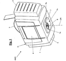
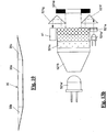
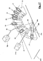
- Fig. 1
- eine Schrägansicht eines Ausführungsbeispiels des erfindungsgemässen Handmessgeräts,
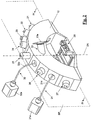
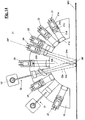
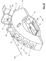
- Fig. 2
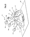
- eine Schrägansicht einer Messanordnung des Handmessgeräts,
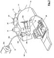
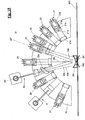
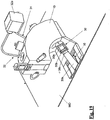
- Fig. 3
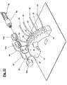
- eine teilweise aufgeschnittene Ansicht der Messanordnung der
Fig. 2 , - Fig. 4
- einen Vertikalschnitt durch die Messanordnung nach der Linie IV-IV der
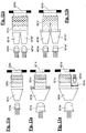
Fig. 2 , - Fig. 5-6
- zwei prinzipielle Ausführungsformen von Beleuchtungseinrichtungen der Messanordnung,
- Fig. 7-8
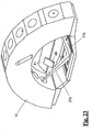
- zwei Detaildarstellungen einer weitschweifigen Beleuchtungseinrichtung und einer beweglichen Weissreferenz der Messanordnung in zwei verschiedenen Stellungen der letzteren,
- Fig. 9
- eine vereinfachte Seitenansicht der Messanordnung mit Strahlengängen zur Verdeutlichung der Verhältnisse bei eingeschobener Weissreferenz,
- Fig. 10
- eine Detaildarstellung der Weissreferent,
- Fig. 11-13
- prinzipielle Darstellungen von verschiedenen Realisierungsformen der Beleuchtungseinrichtungen der Messanordnung,
- Fig. 14
- einen Vertikalschnitt analog
Fig. 4 durch die Messanordnung mit Strahlengängen zur Verdeutlichung der Verhältnisse bei einer Glanzmessung, - Fig. 15
- eine Darstellung analog
Fig. 14 mit einem zusätzlichen Element für Glanzmessungen, - Fig. 16
- eine vereinfachte Seitenansicht analog
Fig. 2 der Messanordnung mit einer zusätzlichen Beleuchtungseinrichtung für Glanzmessungen, - Fig. 17
- einen vereinfachten Schnitt analog
Fig. 4 durch die Messanordnung mit einem zusätzlichen optischen Element für die Erfassung von Transluzenz, - Fig. 18
- eine weiter vereinfachte Seitenansicht der Messanordnung mit einer zusätzlichen Referenz-Beleuchtungseinrichtung,
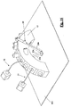
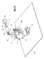
- Fig. 19
- einen Vertikalschnitt durch die Messanordnung entlang der Linie XIX-XIX der
Fig. 18 , - Fig. 20
- einen zur Linie IV-IV der
Fig. 2 um 90° verdrehten Vertikalschnitt durch die Messanordnung einer um Referenzkanäle erweiterten Ausführungsform des Handmessgeräts, - Fig. 21
- eine vereinfachte Schrägansicht der Messanordnung der
Fig. 20 , - Fig. 22
- eine Prinzipskizze einer weiteren Realisierungsform der Beleuchtungseinrichtungen,
- Fig. 23-24
- zwei Prinzipskizzen einer alternativen Realisierungsform einer Weissreferenz,
- Fig. 25
- ein Blockschema der optischen und elektronischen Komponenten des Handmessgeräts und
- Fig. 26
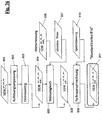
- ein Blockschema der Messwertaufbereitung des Handmessgeräts.
- Fig. 1
- an oblique view of an embodiment of the inventive hand-held measuring device,
- Fig. 2
- an oblique view of a measuring arrangement of the hand-held measuring device,
- Fig. 3
- a partially cutaway view of the measuring arrangement of
Fig. 2 . - Fig. 4
- a vertical section through the measuring arrangement along the line IV-IV of
Fig. 2 . - Fig. 5-6
- two principal embodiments of illumination devices of the measuring arrangement,
- Fig. 7-8
- two detailed views of a long-tailed illumination device and a movable white reference of the measuring arrangement in two different positions of the latter,
- Fig. 9
- a simplified side view of the measuring arrangement with beam paths to illustrate the conditions with inserted white reference,
- Fig. 10
- a detailed description of Weissreferent,
- Fig. 11-13
- basic representations of different forms of implementation of the illumination devices of the measuring arrangement,
- Fig. 14
- a vertical section analog
Fig. 4 through the measuring arrangement with beam paths to clarify the conditions in a gloss measurement, - Fig. 15
- a representation analog
Fig. 14 with an additional element for gloss measurements, - Fig. 16
- a simplified side view analog
Fig. 2 the measuring arrangement with an additional illumination device for gloss measurements, - Fig. 17
- a simplified section analog
Fig. 4 by the measuring arrangement with an additional optical element for the detection of translucency, - Fig. 18
- a further simplified side view of the measuring arrangement with an additional reference illumination device,
- Fig. 19
- a vertical section through the measuring arrangement along the line XIX-XIX of
Fig. 18 . - Fig. 20
- one to the line IV-IV of the
Fig. 2 90 ° twisted vertical section through the measuring arrangement of an extended by reference channels embodiment of the hand-held measuring device, - Fig. 21
- a simplified perspective view of the measuring arrangement of
Fig. 20 . - Fig. 22
- a schematic diagram of a further embodiment of the illumination devices,
- Fig. 23-24
- two schematic diagrams of an alternative realization form of a white reference,
- Fig. 25
- a block diagram of the optical and electronic components of the hand-held device and
- Fig. 26
- a block diagram of the measured value preparation of the handheld instrument.
Für die nachfolgende Figurenbeschreibung gilt folgende Festlegung: Sind in einer Figur einzelne Bezugszeichen nicht eingetragen, so wird diesbezüglich auf die übrigen Figuren und die dazu gehörigen Beschreibungsteile verwiesen. Unter den verkürzten Begriffen "Messgerät" und "Gerät" wird immer ein Handmessgerät verstanden, das für die Erfassung der zur eingangs definierten "Appearance" beitragenden Eigenschaften eines Messobjekts ausgebildet ist. Unter "Messanordnung" wird die Gesamtheit derjenigen Komponenten des Handmessgeräts verstanden, welche zur Beleuchtung eines Messflecks auf der Oberfläche eines Messobjekts und zur Erfassung des von diesem Messfleck zurückgestrahlten Lichts und zur Umwandlung desselben in korrespondierende elektrische Signale dienen. Unter "Gerätenormale" wird eine gedachte, gerätefeste gerade Linie verstanden, die im Wesentlichen durch den Mittelpunkt der Messöffnung des Messgeräts verläuft und bei auf einem ebenen Messobjekt positioniertem Messgerät senkrecht auf dem Messobjekt steht. Üblicherweise liegt die Ebene der Messöffnung parallel zur Oberfläche des Messobjekts, so dass die Gerätenormale auch senkrecht auf der Messöffnung steht. Unter "vertikal" wird die Richtung der Gerätenormalen verstanden. Entsprechend sind Vertikalschnitte als ebene Schnitte durch die Gerätenormale oder parallel zu dieser zu verstehen. Alle Richtungs- bzw. Winkelangaben beziehen sich auf die bezüglich des Messgeräts ortsfeste Gerätenormale.The following definition applies to the following description of the figures: If individual reference symbols are not entered in a figure, reference is made in this regard to the other figures and the associated parts of the description. The abbreviated terms "measuring device" and "device" are always understood to mean a hand-held measuring device which is designed to detect the properties of a test object contributing to the "Appearance" defined above. "Measuring arrangement" is understood to mean the entirety of those components of the hand-held measuring device which serve to illuminate a measuring spot on the surface of a measuring object and to detect the light reflected back from this measuring spot and to convert it into corresponding electrical signals. "Device standards" is understood to mean an imaginary, device-fixed straight line, which runs essentially through the center of the measuring opening of the measuring device and is perpendicular to the measuring object when the measuring device is positioned on a flat measuring object. Usually, the plane of the measurement opening is parallel to the surface of the measurement object, so that the device standard is also perpendicular to the measurement opening. By "vertical" is meant the direction of the device standards. Accordingly, vertical sections are to be understood as planar sections through the device normal or parallel to it. All directions or angles refer to the device standard fixed with respect to the measuring device.
Das in
An der Unterseite weist das Gehäuse H einen Gehäuseboden 5 auf, der durch eine mit einer Messöffnung 6 versehene Basisplatte 7 verstärkt ist. Der Gehäuseboden 5 weist im Bereich der Messöffnung 6 eine nicht bezeichnete Durchbrechung auf, so dass Licht aus dem Gehäuseinneren durch die Durchbrechung und die Messöffnung 6 austreten und umgekehrt Licht von aussen durch die Messöffnung 6 und die Durchbrechung in das Gehäuseinnere eintreten kann. Rund um die Messöffnung 6 sind an der Basisplatte 7 drei Stützorgane 7a, 7b und 7c angeordnet, welche dazu beitragen, dass das Messgerät auch auf gekrümmten Messoberflächen korrekt positioniert werden kann, so dass die Gerätenormale ganz oder zumindest weitestgehend mit der Normalen auf die Messoberfläche im Mittelpunkt des Messflecks (
In der
In seinem generellen Aufbau entspricht das beschriebene Messgerät (mit Ausnahme der Stützorgane) im Grundsatz soweit herkömmlichen Messgeräten dieser Art, so dass der Fachmann diesbezüglich keiner weiteren Erläuterung bedarf.In its general structure, the measuring device described (with the exception of the supporting organs) in principle as far as conventional measuring devices of this type, so that the expert in this regard requires no further explanation.
Die grundsätzliche Ausbildung der Messanordnung MA geht aus den
Die sieben Beleuchtungseinrichtungen 21-27 beleuchten einen Messfleck oder ein Messfeld MF (Figuren 9 und 14) an der Oberfläche eines Messobjekts MO gerichtet unter verschiedenen, auf die Gerätenormale DN bezogenen Beleuchtungswinkeln, und zwar unter nominell -60°, -45°, -30°, -20°, 0°, +30°, +45° und +65° (positive Zählung entgegen dem Uhrzeigersinn ausgehend von der Gerätenormalen DN). Mit nominell ist jeweils der Hauptstrahl bzw. die optische Achse des Beleuchtungsstrahlenbündels gemeint. Die Öffnungswinkel der Strahlenbündel liegen im Bereich von < +/-2° für Messgeometrieen nahe beim spekularen Reflex (Winkeldifferenz <= 25°) und bis etwa +/- 5°-10° für die Messgeometrien, welche grössere Winkeldifferenzen zum spekularen Glanzwinkel haben. Alle sieben Beleuchtungseinrichtungen 21-27 sind so angeordnet, dass die optischen Achsen bzw. Hauptstrahlen der von ihnen erzeugten Beleuchtungsstrahlenbündel in einer durch die Gerätenormale DN verlaufenden Ebene liegen, die im Folgenden kurz als System-Ebene SP bezeichnet und in
Zwei der drei Aufpickeinrichtungen 31-33 sind als örtlich integrale spektrale Messkanäle ausgebildet, die dritte Aufpickeinrichtung ist als örtlich auflösender Farbmesskanal ausgebildet. Sie empfangen das im Bereich des beleuchteten Messflecks des Messobjekts remittierte Messlicht unter Betrachtungswinkeln von +15° und +45°. Die beiden spektralen Messkanäle 31 und 32 umfassen zwei Spektrometer 31 a und 32a, denen das Messlicht mittels Einkoppellinsen 31b bzw. 32b und Lichtleiter 31c bzw. 32c zugeführt wird (
Die beschriebene Messgeometrie ist genau umgekehrt im Vergleich zu den ASTM Standards E2194 und E2539, wo für Messungen an metallischen und perlmuttartige Effektpigmenten zwei gerichtete Beleuchtungen unter 15° und 45° und sechs gerichtete Spektralkanäle unter 0°,30°,65°, -20°, -30° und -60° definiert sind.The measurement geometry described is exactly the opposite of the ASTM standards E2194 and E2539, where for measurements on metallic and pearlescent effect pigments two directed illuminations below 15 ° and 45 ° and six directed spectral channels below 0 °, 30 °, 65 °, -20 ° , -30 ° and -60 ° are defined.
Die zusätzliche Beleuchtungseinrichtung 22 (-45°) ist für Glanzmessungen in Kombination mit dem ersten spektralen Messkanal 31 vorgesehen.The additional illumination device 22 (-45 °) is provided for gloss measurements in combination with the first
Die Beleuchtungseinrichtung 21 umfasst eine Primärlichtquelle 21a z.B. in Form einer Leuchtdiode (oder ggf. auch mehrerer Leuchtdioden), einen Kollimator 21b, eine Mischoptik (Homogenisator) 21c, eine Feldblende mit Apertur 2 1 d und eine Linse 21e. Die Feldblende mit Apertur 21d bildet eine Sekundärlichtquelle, deren Licht über die Linse 21e auf das Messobjekt gerichtet wird. Die übrigen sechs Beleuchtungseinrichtungen 22-27 sind identisch wie die Beleuchtungseinrichtung 21 ausgebildet. Um die Figuren zeichnerisch nicht zu überladen, sind die einzelnen Komponenten der Beleuchtungseinrichtungen 21-27 in
Die
Die Beleuchtungseinrichtungen 21-27 sind nachstehend gesamthaft auch als Beleuchtungssystem bezeichnet.The lighting devices 21-27 are hereinafter also referred to collectively as the lighting system.
Die beiden Spektrometer 31a und 32a lösen das ihnen unter den Betrachtungswinkeln 45° bzw. 15° zugeführte Messlicht spektral auf und erzeugen pro Messung jeweils einen Satz von s Spektralmesswerten integral über den gesamten erfassten Messfleck des Messobjekts, wobei s die Anzahl der aufgelösten Wellenlängenbereiche ist. Die Spektrometer sind vorzugsweise durch Dioden-Array-Spektrometer realisiert, welche eine schnelle simultane Messung über das volle Spektrum ermöglichen.The two
Die RGB-Kamera 33a löst das ihr unter dem Betrachtungswinkel 15° zugeführte Messlicht sowohl örtlich als auch nach drei Farben RGB auf und erzeugt dementsprechend pro Messung einen Rohdatensatz von 3*n Messwerten, wobei n die Anzahl der aufgelösten Bildpunkte ist.The
Die drei Aufpickeinrichtungen bzw. Messkanäle und die in ihnen enthaltenen Lichtwandler (Spektrometer und Farbkamera) sind nachfolgend auch kurz als Detektorsysteme bzw. Detektoren bezeichnet.The three Aufpickeinrichtungen or measuring channels and the light transducers contained therein (spectrometer and color camera) are hereinafter also referred to as detector systems or detectors.
Für die Analyse von visueller Textur ist ein Detektor auf Basis einer örtlich auflösenden Kamera erforderlich, um die für die Textur-Analyse benötigte örtliche Bild-Infonnation zu erhalten. Das Kamera-Objektiv muss dabei spektrale Anforderungen, örtliche (Auflösungs-) Anforderungen und Winkel- und Geometrieanforderungen erfüllen. Das Ziel ist es, Bilddaten zu erfassen, die mit der visuellen Textur korrelieren. Allgemeine Anforderungen an die örtlich auflösende Aufpickeinrichtung 33 sind:
Die optische Auflösung der gemessenen Bild-Daten ist unter der visuellen Auflösungsgrenze bei Nahpunkt-Betrachtungsdistanz. Eine vernünftige Grenze kann unter der Annahme berechnet werden, dass die übliche Nahpunkt-Betrachtungsdistanz 250 mm und das Winkelauflösungsvermögen im besten Fall 60 Linienpaare pro Grad betragen. Das optische Design der Kamera muss eine bessere optische Auflösung aufweisen, d.h. die örtliche Grenzfrequenz muss über 14 Linienpaare pro mm in der Messebene liegen.For visual texture analysis, a local resolution camera based detector is required to obtain the spatial image information needed for texture analysis. The camera lens must meet spectral requirements, local (resolution) requirements and angle and geometry requirements. The goal is to capture image data that correlates with the visual texture. General requirements for the on-
The optical resolution of the measured image data is below the visual resolution limit at near-point viewing distance. A reasonable limit can be calculated on the assumption that the usual near-point viewing distance is 250 mm and the angular resolution is at best 60 line pairs per degree. The optical design of the camera must have a better optical resolution, ie the local cutoff frequency must be more than 14 line pairs per mm in the measurement plane.
Um Informationsverlust zu vermeiden, muss das Sensorfeld der Kamera in der Bildebene genügend digitales Oversampling ermöglichen. Vorzugsweise wird ein Oversampling um mindestens einen Faktor 2 angewandt. Eine Bildpunkt-Grösse von ungefähr 20 µm in der Objekt-Ebene (Messfläche) ist ausreichend.In order to avoid loss of information, the sensor field of the camera in the image plane must allow sufficient digital oversampling. Preferably, an oversampling by at least a factor of 2 is used. A pixel size of approximately 20 μm in the object plane (measuring surface) is sufficient.
Der Konus- oder Apertur-Winkel des Aufpickstrahlengangs in der Objekt-Ebene muss relativ klein sein, vorzugsweise unter 1°. Der Aperturwinkel im Aufpickstrahlengang ist durch den Durchmesser der Apertur der Feldblende und die Brennweite des Objektivs bestimmt.The cone or aperture angle of the pick-up beam path in the object plane must be relatively small, preferably less than 1 °. The aperture angle in the pick-up beam path is determined by the diameter of the aperture of the field stop and the focal length of the objective.
Die Detektorsysteme (Aufpickeinrichtungen) erfassen das Messlicht unter einem von 0° abweichenden Winkel zur Gerätenormalen. Dies erfordert die Anwendung der sog. Scheimpflug-Bedingung, um scharfe Abbildungsbedingungen über das Messfeld zu erreichen, falls die Fokustiefe in der Bildebene nicht ausreicht.The detector systems (picking devices) detect the measuring light at an angle other than 0 ° to the device standard. This requires the use of the so-called Scheimpflug condition to achieve sharp imaging conditions over the field of view if the depth of focus in the image plane is insufficient.
Ferner ist es von Vorteil, wenn in der Objekt-Ebene ein angenähert telezentrischer Strahlenverlauf implementiert wird, um winkelmässig konstante Messbedingungen über das gesamte Messfeld zu erreichen und Störungen und Vergrösserungsdifferenzen möglichst niedrig zu halten.Furthermore, it is advantageous if an approximately telecentric beam path is implemented in the object plane in order to achieve angularly constant measuring conditions over the entire measuring field and to keep disturbances and magnification differences as low as possible.
Die Beleuchtungseinrichtung 28 ist vorgesehen, damit das Messgerät auch einen Messmodus mit weitschweifigen Beleuchtungsbedingungen unterstützt. Die Beleuchtungseinrichtung 28 ist als LED-Hintergrundbeleuchtung ausgelegt, welche das Messobjekt direkt aus einem grossen Raumwinkel beleuchtet.The
Die Beleuchtungseinrichtung 28 ist in den
Alternativ oder zusätzlich kann auch eine Ring-Beleuchtungseinrichtung vorgesehen sein, wie sie z.B. in den Farbmess-Standards CIE15.3 für die 45°/0°-Messgeometrie definiert ist. Eine Ring-Beleuchtung hat den Vorteil, dass sie lageunabhängige Messwerte liefert, d.h. dass die Drehstellung des Messgeräts auf dem Messobjekt keinen Einfluss auf das Messergebnis hat.Alternatively or additionally, it is also possible to provide a ring illumination device, as used e.g. defined in the color measurement standards CIE15.3 for the 45 ° / 0 ° measurement geometry. Ring lighting has the advantage of providing position-independent readings, i. that the rotational position of the measuring instrument on the measuring object has no influence on the measuring result.
Das erfindungsgemässe Messgerät ist im dargestellten Ausführungsbeispiel ferner mit einer integrierten Weissreferenz in Form einer Weisskachel ausgestattet, welche für Kalibrationszwecke in die Strahlengänge der Beleuchtungseinrichtungen 21-27 und der Aufpickeinrichtungen 31-33 einbringbar ist. Im konkreten Ausführungsbeispiel besteht die Weisskachel aus einer an ihrer Oberseite ebenen Platte 35, welche knapp oberhalb der Messöffnung 6 senkrecht zur System-Ebene SP (elektrisch angetrieben) verschiebbar angeordnet ist. Beim nonnalen Messeinsatz des Messgeräts befindet sich die Weisskachel 35 in der in
Die Weisskachel 35 liegt gegenüber der Oberfläche des Messobjekts MO (Messebene) erhöht. Wie man aus
Gemäss eines weiteren wichtigen Aspekts der Erfindung ist nun durch eine spezielle Ausbildung der Weisskachel dafür Sorge getragen, dass Beleuchtungslicht aus den seitlichen randnäheren beleuchteten Zonen der Weisskachel 35 zu deren zentraler Zone transportiert wird, wo es von den Aufpickeinrichtungen 31-33 erfasst werden kann.According to another important aspect of the invention, a special design of the white tile ensures that illumination light is transported from the lateral edge closer illuminated zones of the
Die spezielle Ausbildung geht aus der Schnittdarstellung (Vertikalschnitt parallel zu der in
Der mittlere Abschnitt 35a ist so bemessen, dass er möglichst vollständig im Erfassungsbereich der Aufpickeinrichtungen 31-33 liegt. In ihm auftreffendes Beleuchtungslicht wird so direkt von den Aufpickeinrichtungen 31-33 erfasst. In den beiden äusseren Abschnitten 35b und 35c auftreffendes Licht wird durch Mehrfachreflexion zum mittleren Abschnitt 35a geleitet und dann ebenfalls von den Aufpickeinrichtungen 31-33 erfasst.The middle section 35a is dimensioned such that it lies as completely as possible within the detection range of the picking devices 31-33. Illumination light incident in it is thus detected directly by the picking devices 31-33. Light incident in the two
Die Weisskachel 35 dient auch als mechanischer Verschluss des Messgeräts, um dessen Inneres, insbesondere die optischen Komponenten, vor Verschmutzung zu schützen.The
Die
Die in
Die Beleuchtungseinrichtung der
Die Beleuchtungseinrichtung der
Die Beleuchtungseinrichtung der
Die Beleuchtungseinrichtung der
Die
Unabhängig davon, ob zusätzliche Primärlichtquellen eingesetzt werden oder nicht, kann der nicht genutzte Teil der Etendue der Primärlichtquelle dazu verwendet werden, Licht für eine Referenzlichtmessung auszukoppeln. Darauf wird weiter unten noch näher eingegangen. Durch die sachgemässe Ausgestaltung des Homogenisators 521 c ist gewährleistet, dass das ausgekoppelte Licht mit der spektralen Radianz in der Apertur 521 d der sekundären Lichtquelle korreliert.Regardless of whether additional primary light sources are used or not, the unused portion of the etendue of the primary light source can be used to extract light for reference light measurement. This will be discussed in more detail below. The proper design of the
Es sei noch erwähnt, dass der "nicht verwendete Teil der Etendue" in den 2D-Darstellungen der Figuren 12a, 12b, 13a und 13b als nicht genutzter Teile der (Ausgangs-) Flächen der Optiken (Kollimator, Homogenisator) veranschaulicht ist, jedoch im Allgemeinen auch als nicht ausgenutzter Raumwinkelbereich aufgefasst werden kann.It should be noted that the "unused portion of the etendue" in the 2D representations of Figures 12a, 12b, 13a and 13b is illustrated as unused portions of the optics (collimator, homogenizer) surfaces Generally also as unused solid angle range can be understood.
Wie sich aus dem Vorstehenden ergibt, sind die Beleuchtungseinrichtungen modular und prinzipiell gleich aufgebaut. Die gerichteten Beleuchtungseinrichtungen überleuchten den von den Aufpickeinrichtungen erfassten Messfeldbereich. Die ASTM Standards für Messungen an metallischen oder perlmuttartigen Effektpigmenten fordern eine hohe Genauigkeit für die Beleuchtungswinkel. Gleichzeitig ist aber eine flexible Wahl der Lichtquellen wünschenswert, ohne dass die Winkeleigenschaften der gerichteten Beleuchtung beeinflusst werden. Dazu gehören der Einfallswinkel des Hauptstrahls, der Divergenzwinkel über das Messfeld und der Aperturwinkel. Dies wird erreicht durch die vorstehend beschriebene Ausbildung der Beleuchtungseinrichtungen mit einer primären Lichtquelle und einer davon entkoppelten sekundären Lichtquelle. Die sekundäre Lichtquelle ist durch eine präzise mechanische Apertur realisiert, welche genau auf die Kollimatorlinse ausgerichtet montiert ist. Die Grösse und Position der sekundären Lichtquelle in Kombination mit der Brennweite der Kollimatorlinse definieren die Winkeleigenschaften der Beleuchtungseinrichtungen. Die Grösse und die Position der sekundären Lichtquelle kann für die einzelnen Beleuchtungseinrichtungen verschieden sein.As can be seen from the above, the lighting devices are modular and basically the same structure. The directional illumination devices are superimposed on the measurement field area detected by the pickup devices. The ASTM standards for measurements on metallic or pearlescent effect pigments demand a high accuracy for the illumination angles. At the same time, however, a flexible choice of the light sources is desirable without affecting the angular properties of the directional illumination. These include the angle of incidence of the main beam, the angle of divergence across the field of view and the aperture angle. This is achieved by the above-described embodiment of the illumination devices with a primary light source and a secondary light source decoupled therefrom. The secondary light source is realized by a precise mechanical aperture, which is mounted exactly aligned with the collimator lens. The size and position of the secondary light source in combination with the focal length of the collimator lens define the angular characteristics of the illuminators. The size and position of the secondary light source may be different for the individual lighting devices.
Das Konzept mit sekundären Lichtquellen erfordert, dass die Lichtquellen im Nah- und Femfeld homogenisiert sind. Die Homogenisierung des Nahfeldes erstreckt sich über den Bereich der Apertur der Feldblende, die Homogenisierung des Fernfeldes über den Bereich des Aperturwinkels der Kollimationsoptik bzw. Linse in der Beleuchtungseinrichtung. Dabei kann zwischen spektraler und räumlicher Homogenisierung unterschieden werden. Spektrale Homogenisierung heisst, dass die Radianz der sekundären Lichtquelle für jeden Winkel und Ort eine möglichst gleiche spektrale Verteilung aufweist. Räumliche Homogenisierung heisst, dass die Radianz für jeden Ort der sekundären Lichtquelle möglichst gleiche Amplitude sowie möglichst gleiche Amplitude in Funktion des Winkels aufweist. In Kombination mit der Kollimationsoptik bzw. Linse in der Beleuchtungseinrichtung ist zudem ein spezifischer Verlauf der Radianz in Funktion des Winkels bevorzugt um eine bevorzugte räumliche Verteilung der Irradianz im Messfeld MF zu erhalten.The concept with secondary light sources requires that the light sources in the near and far field be homogenized. The homogenization of the near field extends over the area of the aperture of the field stop, the homogenization of the far field over the range of the aperture angle of the collimating optics or lens in the illumination device. It is possible to distinguish between spectral and spatial homogenization. Spectral homogenization means that the radiance of the secondary light source has the same spectral distribution as possible for every angle and location. Spatial homogenization means that the radiance for each location of the secondary light source has the same amplitude as possible as well as possible equal amplitude in function of the angle. In addition, in combination with the collimation optics or lens in the illumination device, a specific course of the radiance as a function of the angle is preferred in order to obtain a preferred spatial distribution of the irradiance in the measurement field MF.
Dieses Ziel wird nach einem Aspekt der Erfindung erreicht durch eine geeignete Kombination der abbildenden und/oder nichtabbildenden Funktionsblöcke Kollimator, Homogenisator und Diffusor (optional). Ein typischer Homogenisator ist z.B. ein Lichtleiter aus Glas oder Kunststoff mit quadratischem Querschnitt. Die räumliche Homogenisierung mit Lichtleitern erzeugt in der Regel eine Inhomogenität im Fernfeld, die durch ein zusätzliches Diffusor-Element mit angepassten Streuwinkeln behoben werden kann.This object is achieved according to one aspect of the invention by a suitable combination of the imaging and / or non-imaging function blocks collimator, homogenizer and diffuser (optional). A typical homogenizer is e.g. a light guide made of glass or plastic with a square cross-section. The spatial homogenization with light guides usually produces a inhomogeneity in the far field, which can be remedied by an additional diffuser element with adapted scattering angles.
Da die spektrale Analyse in den Aufpickeinrichtungen 31 und 32 erfolgt, müssen die Lichtquellen der Beleuchtungseinrichtungen über den gesamten interessierenden Spektralbereich genügend leistungsfähig sein. Der Spektralbereich erstreckt sich über den sichtbaren Wellenlängenbereich von 400 nm bis 700 nm. Für spezielle Anwendungen kann auch eine Ergänzung um UV und nahes IR erforderlich sein. Durch den Einsatz von LED Technologie können die spektralen Eigenschaften der Lichtquellen bzw. Beleuchtungseinrichtungen relativ flexibel realisiert werden. Weisse LEDs können dabei für die Erzeugung von über das ganze sichtbare Spektrum kontinuierlichem Licht eingesetzt werden. Zusätzliche LEDs, die ausserhalb des für weisse LEDs typischen Spektralbereichs emittieren, können den Spektralbereich der Beleuchtungseinrichtungen ergänzen. Dazu gehören vor allem LEDs, die im violetten, UV und NIR Bereich emittieren.Since the spectral analysis is carried out in picking
In der Praxis müssen nicht alle Beleuchtungseinrichtungen für den vollen Spektralbereich ausgelegt sein. Wenigstens eine der Beleuchtungseinrichtungen ist für den vollen Spektralbereich von 400 nm - 700 nm ausgebildet, die anderen Beleuchtungseinrichtungen können für einen reduzierten Spektralbereich ausgelegt werden. In diesem Fall wird die bei Verwendung dieser Beleuchtungseinrichtungen fehlende spektrale Information aus der spektralen Information der für den vollen Spektralbereich ausgelegten Beleuchtungseinrichtung interpoliert.In practice, not all lighting equipment must be designed for the full spectral range. At least one of the illumination devices is designed for the full spectral range from 400 nm to 700 nm, the other illumination devices can be designed for a reduced spectral range. In this case, the missing with the use of these lighting devices spectral information from the spectral information of the designed for the full spectral range lighting device is interpolated.
Für Glanzmessungen mit dem erfindungsgemässen Messgerät wird die unter -20° angeordnete Beleuchtungseinrichtung 24 eingesetzt, das remittierte Messlicht wird mit den unter 15° angeordneten Aufpickeinrichtungen 32 und 33 erfasst. Die Messfeldgrösse und die Divergenzwinkel der Beleuchtungs- und Aufpickstrahlengänge sind so gewählt, dass wenigstens an einer Stelle des Messfelds eine gerichtete Reflexionsbedingung für den Beleuchtungsstrahl und den Aufpickstrahl herrscht. An dieser Stelle wird der direkte Glanz von der Kamera detektiert. Die Winkelbedingungen zwischen den reflektierten Lichtstrahlen und den Aufpickstrahlen variieren über das Messfeld. Die mit der Kamera aufgenommenen Bilddaten ermöglichen für die anderen Stellen des Messfelds die Detektion der Reflexionscharakteristik nahe beim Spiegel-Winkel. Die Bilddaten können in vorkalibrierte örtliche Bereiche aufgeteilt werden, die vordefinierten Bereichen mit ähnlicher Winkeldifferenz zur jeweils lokalen Spiegelrichtung entsprechen.For gloss measurements with the measuring device according to the invention, the
Die unter -45° angeordnete Beleuchtungseinrichtung 22 kann ebenfalls für Glanzmessungen herangezogen werden, wobei für die unter 45° angeordnete Aufpickeinrichtung 31 die Bedingung spiegelnder Reflexion erfüllt ist.The
In
Die Glanz-Erfassung beim spekularen Glanz bei typisch 20° oder 45° und die Erfassung der Glanz-Verteilung um den spekularen Glanz, in einem Winkelbereich von typischerweise + / - 20°, kann gemäss der in
Durch das optische Element 39 werden im begrenzten Bildfeld des Messgerätes aspekulare Winkel im Bereich des direkten Glanzes sichtbar und mit der Kamera quantitativ messbar. Die erfassbaren Quantitäten sind der spekulare Glanz der Materialoberfläche, der typischerweise gegeben ist durch den Fresnel-Reflex des Materials oder des Decklackes (bei mehrschichtig lackierten Messobjekten) und die Breite der Streukeule um den Reflex, die typischerweise bestimmt wird durch die Rauheit der Oberfläche. Im weiteren erlaubt die Analyse der Bild-Textur die Erfassung der Variation der Glanzeigenschaften von Effektpigmenten, die Variation der Dichte und Farberscheinung der Effektpigmente und so auch die typische Lebensdauer der Effekte mit änderndem Betrachtungswinkel. Diese Daten sind insbesondere interessant zu Erfassung der Material Erscheinung (Appearance), einerseits zur Visualisierung aber auch zur Material-Klassifizierung und Material-Suche in einer Material-Bibliothek oder einem Material-Katalog. Durch sogenanntes inverses Ray Tracing können Parameter für fotorealistische Computer Simulationen gewonnen werden, um bei Bedarf das untersuchte Material, also seine Apperance, typischerweise von einem Autolack, auf dem Computer auf ein ganzes Fahrzeug anzuwenden. Dieses Konzept ist auch von Interesse für die unterschiedlichsten Materialen wie Kunststoffe, Beläge, Papiere, Druckerzeugnisse, Textilien und mehr.As a result of the
Internationale Standards schreiben für Glanzmessung andere Messgeometrien vor als für Mehrwinkel-Farbmessung. Der Standard ASTM E430 beschreibt eine Methode zur Messung des Glanzes von hochglänzenden Oberflächen mittels Goniophotometrie. Der Standard spezifiziert Spiegelglanzmessung bei 20° oder 30°.International standards prescribe different measurement geometries for gloss measurement than for multi-angle color measurement. The standard ASTM E430 describes a method for measuring the gloss of high-gloss surfaces by means of goniophotometry. The standard specifies mirror gloss measurement at 20 ° or 30 °.
Im vorliegenden Messgerät können die unter 15° angeordneten Aufpickeinrichtungen 32 und 33 auch auf eine alternative Weise für Glanzmessungen mit einem 20°-Spiegelwinkel benutzt werden. Zu diesem Zweck ist der erfasste örtliche Messbereich der Aufpickeinrichtung 33 bzw. der Kamera 33a in Richtung quer zur System-Ebene ausreichend gross gewählt. Der Sicht- bzw. Erfassungswinkel ist grösser als +/- 5° ausgelegt. Das erzeugt einen Aufpickwinkel von 20° an spezifischen ausserhalb der System-Ebene liegenden Stellen des Messfelds. Gemäss eines weiteren Gedankens der Erfindung ist eine zusätzliche Lichtquelle vorgesehen, welche diese spezifischen Stellen des Messfelds unter einem Einfallswinkel von 20° beleuchtet. Die zusätzliche Lichtquelle ist ausserhalb der System-Ebene angeordnet. Vorteilhafterweise ist das optische System dieser Lichtquelle so ausgelegt, dass es einen grösseren Divergenzwinkel über den örtlichen Erfassungsbereich der Kamera erzeugt. Dies ermöglicht die Erfassung eines grösseren Winkelbereichs der Glanzvariation über das Bild. Vorzugsweise ist die Lichtquelle als Punktlichtquelle ausgebildet, z.B. als ein divergierendes Strahlenbündel erzeugende Austrittsfläche eines optischen Lichtleiters. Die Lichtquelle kann auch eine eindimensional längliche Gestalt aufweisen, um einen grösseren Bereich zu beleuchten, in welchem die Bedingung für spiegelnde Reflexion erfüllt ist. Die längliche Lichtquelle kann z.B. durch eine lineare Anordnung von Lichtleitern realisiert sein.In the present gauge, the 15 °
Vorzugsweise kann auch eine zweite Lichtquelle derselben Art symmetrisch auf der gegenüberliegenden Seite der System-Ebene vorgesehen sein. Die mittels der beiden Lichtquellen erzeugten Bilddaten ermöglichen die Charakterisierung des anisotropen Verhaltens der Glanzverteilung in verschiedenen Richtungen.Preferably, a second light source of the same type can be provided symmetrically on the opposite side of the system level. The image data generated by the two light sources allow the characterization of the anisotropic behavior of the gloss distribution in different directions.
In
In
Die ohne und mit eingeschobener Linse ermittelten spektralen Messwerte werden zur Bestimmung einer spektralen Transluzenz-Korrektur benutzt. Aus den spektralen Messwertdifferenzen der beiden Messungen wird ein spektraler Korrekturfaktor abgeleitet und auf alle anderen Messgeometrien (also Messungen unter Verwendung der Beleuchtungseinrichtungen 21-26) angewandt.The spectral measured values determined with and without inserted lens are used to determine a spectral translucency correction. From the spectral measured value differences of the two measurements, a spectral correction factor is derived and applied to all other measurement geometries (ie measurements using the illumination devices 21-26).
Die
In der Firmware des Messgeräts ist eine kalibrierte spektrale Transmissionskurve der Lichtquelle/Filter-Kombination der Referenzbeleuchtungseinrichtung enthalten. Die Referenzbeleuchtungseinrichtung wird bei jeder Weisskachel-Kalibration verwendet und reflektiert das Licht über die Weisskachel in die Aufpickeinrichtungen.Included in the firmware of the meter is a calibrated spectral transmission curve of the light source / filter combination of the reference illuminator. The reference illuminator is used with each white tile calibration and reflects the light across the white tile into the pickup devices.
Die Referenz-Beleuchtungseinrichtung 30 könnte, sofern es die Platzverhältnisse zulassen, wie die Beleuchtungseinrichtungen 21-27 in der System-Ebene SP angeordnet sein.The
Die
Anstatt mittels der Strahlenteiler kann die Auskoppelung des Lichts aus den Beleuchtungseinrichtungen 21-27 auch mittels vor dem nicht genutzten Teil der Etendue angeordneten Umlenkprismen (oder funktionsäquivalenten optischen Bauteils) erfolgen, welche das ausgekoppelte Licht über die Lichtleiter 41-47 in die Referenzaufpickvorrichtung 34 leiten. In
Anstelle der Referenzkanäle mit Lichtleitern und einer Referenzaufpickeinrichtung 34 können die LED Lichtquellen alternativ auch mit einer einfacheren und kompakteren Referenzeinrichtung charakterisiert werden, wie z.B. einem RGB Sensor. Ein solcher Sensor ist sehr kompakt und lässt sich dementsprechend direkt bei den LED Mischern montieren, z.B. wie oben ausgeführt am nicht genutzten Ausgangsbereich des Kollimators. Zwar lässt ein solch vereinfachter Referenzkanal keine exakte spektrale Korrektur zu, der LED-Pegel und gewisse spektrale Veränderungen wie z.B. die relative Stärke des blauen LED-Peaks im Vergleich zum Phosphorpeak lassen sich aber sehr wohl korrigieren, so dass die grössten Drift-Fehler der LED Beleuchtung ebenfalls wegkalibriert werden können.Alternatively, instead of the reference channels with optical fibers and a
Die
Durch diese Realisierungsform der Beleuchtungseinrichtungen 21-27 wird erreicht, dass nach der Verteilung des Ausgangslichtes des Homogenisators der Lichtquelle 50 durch den Multiplexer 59 das Licht in den Beleuchtungskanälen 21-27 und im Referenzspektralmodul 34a bestmöglich korrelieren.As a result of this form of implementation of the illumination devices 21-27, the light in the illumination channels 21-27 and in the reference
Eine andere Realisierungsform einer Weissreferenz ist in den
Durch den Spiegel 61 wird das Messfeld MF in ein virtuelles Messfeld gespiegelt, wobei sich der diffuse Reflektor 60 am Ort des virtuellen Messfelds befindet. Der diffuse Reflektor 60 bildet die eigentliche Weissreferenz bzw. Weisskachel und wird über den Spiegel von den Beleuchtungseinrichtungen 21-27 beleuchtet. Die Rückstreuung des diffusen Reflektors wird über den Spiegel 61 von den Aufpickanordnungen 31-33 genau so gemessen, wie wenn sie vom realen Messfeld herkäme. Auch die Beleuchtung des virtuellen Messfeldes bzw. Reflektors 60 ist identisch zum Messfeld. Die Winkel/Ortsverhältnisse bei dieser Ausbildung der Weissreferenz sind also identisch zu einer Kalibration mit einer Weisskachel im (realen) Messfeld. Der Spiegel 61 und der diffuse Reflektor 60 (die eigentliche Weisskachel) können auch zu einem einzelnen Bauteil mit einem Glas- oder Kunststoffkörper kombiniert werden.The
Alternativ ist ferner auch noch die folgende, eine kompaktere Bauweise ermöglichende Variante möglich. Hierbei ist der diffuse Reflektor 60 (die eigentliche Weisskachel) nicht mehr als vollständig opaker Reflektor, sondern als semi-transparenter Film oder als Matrix aus transparenten und opaken Teilbereichen aufgebaut. Somit muss der Reflektor bzw. das virtuelle Messfeld nicht mehr vollständig ausserhalb der Strahlengänge der Beleuchtungseinrichtungen 21-27 und der Aufpickeinrichtungen 31-33 liegen, womit die Grösse der Kombination Spiegel/Reflektor stark reduziert werden kann.Alternatively, also the following, a more compact design enabling variant is also possible. Here, the diffuse reflector 60 (the actual white tile) is no longer constructed as a completely opaque reflector, but as a semi-transparent film or as a matrix of transparent and opaque subregions. Thus, the reflector or the virtual measuring field no longer has to lie completely outside the beam paths of the illumination devices 21-27 and the pickup devices 31-33, whereby the size of the combination mirror / reflector can be greatly reduced.
Die Grösse des Messfelds und die Grösse der optischen Komponenten hängen für gerichtete Messgeometrien linear zusammen. Die Grösse des Messfelds muss in Abhängigkeit der örtlichen lateralen Grössenvariation auf der Oberfläche des Messobjekts gewählt werden, um eine statistische Repräsentation der örtlich variierenden Oberflächeneigenschaften des Messobjekts zu enthalten. Die Grösse der optischen Systeme wird in Abhängigkeit der Eigenschaften des zu messenden Materials gewählt. Durch Verwendung desselben Beleuchtungssystems kann das Messinstrument mit einem kleineren Messfeld realisiert werden, wobei nur die Aufpickeinrichtungen mit einem kleineren Sichtfeld implementiert werden durch Veränderung der fokalen Eigenschaften des Linsensystems und durch eine zusätzliche mechanische Apertur in der Ebene des Messfelds.The size of the measuring field and the size of the optical components are linearly related to directional measuring geometries. The size of the measuring field must be selected as a function of the local lateral size variation on the surface of the test object in order to contain a statistical representation of the locally varying surface properties of the test object. The size of the optical systems is chosen depending on the properties of the material to be measured. By using the same illumination system, the measuring instrument can be realized with a smaller measuring field, whereby only the picking devices with a smaller field of view are implemented by changing the focal properties of the lens system and by an additional mechanical aperture in the plane of the measuring field.
Die verschiedenen Messfunktionen des Messgeräts für spektrale Farb-, visuelle Textur- und Glanz-Charakterisierung haben ähnliche Anforderungen auf der Beleuchtungsseite aber verschiedene Anforderungen auf der Detektorseite, z.B. (örtlich) integrale Messung über das Messfeld und örtlich aufgelöste Messung.The various measurement functions of the spectral color, visual texture, and gloss characterization meter have similar requirements on the lighting side but different requirements on the detector side, e.g. (local) integral measurement via the measuring field and spatially resolved measurement.
Gemäss des grundlegenden Gedankens der Erfindung werden beim Messgerät Beleuchtungskomponenten geteilt, d.h. für verschiedene Funktionen eingesetzt, und unterschiedliche Messerfordernisse werden in Aufpickeinrichtungen mit demselben Betrachtungswinkel verlagert. Dieses Konzept erlaubt eine kompakte und kosteneffektive mechanische Lösung mit kurzen Gesamt-Messzeiten aufgrund simultaner Messdatenerfassung. Ferner erzeugt dieses Konzept konsistente Messdaten für verschiedene Materialeigenschaften beim selben Betrachtungswinkel. Die Messdatensätze werden zur Berechnung von Appearance Daten bei verschiedenen Betrachtungsdistanzen oder verschiedenen Messbedingungen wie z.B. Beleuchtungsveränderungen benutzt. Die
Die Messung von Appearance Eigenschaften erfordert kalibrierte spektrale Reflektanzfaktor-Messwerte für alle Mess-Geometrien des Mehrwinkel-Messgeräts. Theoretisch könnte dies mittels einer spektral auflösenden Kamera implementiert werden. Spektrale und multi-spektrale Kamera-Technologien sind z.B. in der Publikation
Die Bilddaten müssen für die Radianz des remittierten Lichts im Aufpickstrahlenbündel der Kamera absolut kalibriert sein. Dies wird unter Einsatz der integrierten Weisskachel durch eine absolute spektrale Reflektanz-Kalibration für jede Messgeometrie (Beleuchtungs-/Aufpickeinrichtungskombination) erreicht.The image data must be absolutely calibrated for the radiance of the reflected light in the pick-up beam of the camera. This is achieved by using the integrated white tile by an absolute spectral reflectance calibration for each measurement geometry (lighting / Aufpickeinrichtungskombination).
Effekt-Materialien können grosse Helligkeitsschwankungen in den Bilddaten erzeugen, so dass eine einzelne Messung den Dynamikbereich der Kamera übersteigt. Dieser Problematik wird durch Hoch-Dynamik-Bereich (HDR) Detektionsverfahren begegnet, wie sie z.B. in der Publikation
Im Interesse geringerer Komplexität und niedrigerer Produktionskosten wird gemäss eines grundlegenden Gedankens der Erfindung in der örtlich auflösenden Aufpickeinrichtung 33 keine Spektral-Kamera, sondern eine (vergleichsweise einfache und kostengünstige) RGB Kamera mit einer Bayer-Filteranordnung auf dem eigentlichen Sensorfeld der Kamera eingesetzt. Die erforderliche spektrale Genauigkeit wird gemäss der Erfindung durch Bezug der unter demselben Beobachtungswinkel angeordneten spektralen Aufpickeinrichtung 32 erreicht. Die Strahlengänge der beiden Aufpickeinrichtungen 32 und 33 sind mittels des Strahlenteiles 33c aufgeteilt. Der Strahlenteiler kann Polarisierungseffekte verursachen, welche unerwünscht sind, z.B. weil Effekt Pigmente partiell polarisiertes Licht reflektieren können. Um die Polarisationsabhängigkeit zu minimieren ist die Strahlenteiler-Oberfläche um 45° aus der System-Ebene herausgedreht, wobei das Messlicht für die Kamera aus der System-Ebene herausgeleitet wird. Diese Massnahme gleicht die s und p Polarisationskomponenten aus, welche orthogonal zur System-Ebene stehen.In the interests of less complexity and lower production costs, according to a basic idea of the invention, no spectral camera is used in the locally resolving picking
Für Messanwendungen, welche präzise Farbinformationen erfordern, werden bei jeder Messgeometrie (Kombination Beleuchtungs-/Aufpickeinrichtung) die spektralen Messdaten verwendet. Die spektralen Messdaten werden auch zur Erhöhung der Farbgenauigkeit der Farbbilddaten herangezogen. RGB Kameras können mit aus dem Color Management bekannten Methoden farbkalibriert werden, beispielsweise durch Anwendung eines ICC Kamera Profils. Die erreichbare Farbgenauigkeit ist dabei aber begrenzt und durch Metamerie-Effekte beeinträchtigt (Detektor- und Beleuchtungsmetamerie). Gemäss eines wichtigen Aspekts der Erfindung wird die kolorimetrische Genauigkeit der Farbbilddaten durch Korrektur anhand der aus den spektralen Messdaten erhaltenen Farbinformation erhöht. Dazu wird der Farbwert jedes Bildpunkts so korrigiert, dass der daraus durch Mittelung über das Messfeld berechnete Farbwert mit dem sich aus der spektralen Messung ergebenden integralen Farbwert übereinstimmt. Dies ermöglicht die gemittelte Farbinformation im Bild an unterschiedliche Beleuchtungsspektren anzupassen. Die visuelle Textur-Analyse wird anhand der relativen Farbvariation im Bild vorgenommen, welche typischerweise genauer als die absolute Farbinformation und ausreichend für die meisten Textur-Analyse-Anwendungen ist (vgl. z.B. die Publikation
Das Detektorsystem erzeugt für jede Messgeometrie (Kombination Beleuchtungs-/Aufpickeinrichtung) einen Satz von farbkalibrierten HDR Bilddaten und (örtlich integralen) spektralen Reflektanzdaten. Die Farbbilddaten können mit den spektralen Daten korrigiert werden, um konsistente (örtliche) Mittelwert-Farbinformationen der Bilddaten zu erzeugen. Die Bilddaten enthalten als örtliche Information die über das Messfeld variierende Farbe oder Glanzeigenschaften des Messobjekts.The detector system generates a set of color-calibrated HDR image data and (locally integral) spectral reflectance data for each measurement geometry (combination illumination / pickup device). The color image data may be corrected with the spectral data to produce consistent (local) average color information of the image data. The image data contain as local information the color or gloss properties of the object to be measured which vary over the measuring field.
Die farbkalibrierten HDR Bilddaten liegen in einer Auflösung vor, die über der Auflösungsgrenze des menschlichen Auges liegt. Mit diesen Bilddaten als Eingangsdaten wird ein geeignetes Appearance Bild berechnet, das mit dem visuellen Bildeindruck bei einer bestimmten Betrachtungsdistanz übereinstimmt. Dazu ist die Anwendung eines Farb-Appearance Modells mit Anpassung an verschiedene örtliche Auflösungen erforderlich.The color-calibrated HDR image data are at a resolution that is above the resolution limit of the human eye. With these image data as input data, a suitable appearance image is calculated that matches the visual image impression at a certain viewing distance. This requires the use of a color appearance model with adaptation to different local resolutions.
Das Sichtfeld (der erfassbare Bereich) der örtlich auflösenden Aufpickeinrichtung 33 ist gleich oder grösser ausgelegt als das Sichtfeld der spektralen Aufpickeinrichtungen 31 und 32. Für die Farbkorrektur der Bilddaten wird nur der partielle Bildinhalt berücksichtigt, der dem überlappenden Bereich der Sichtfelder entspricht.The field of view (the detectable area) of the spatially resolving
Die
Den Ausgangspunkt bilden die HDR Farbbilddaten der Kamera (Block 601), die aus mehreren dunkelkompensierten Einzelbelichtungen (Messungen mit unterschiedlichen Integrationszeiten) erstellt sind (siehe weiter oben). Die Farbbilddaten zeigen ein Farbfiltermuster. Das Signal ist proportional zum einfallenden Licht. Die optische und räumliche Auflösung ist kameraspezifisch.The starting point is the HDR color image data of the camera (block 601), which are made up of several dark-compensated single exposures (measurements with different integration times) (see above). The color image data shows a color filter pattern. The signal is proportional to the incident light. The optical and spatial resolution is camera-specific.
In einem ersten Schritt (Block 602) wird eine Auflösungsanpassung vorgenommen. Dabei werden die räumliche und optische Auflösung so angepasst, dass sie einer definierten Ausgabeauflösung (Ziel-Auflösung) entsprechen. Aus Stabilitäts- und Genauigkeitsgründen ist die Ausgabeauflösung meist gröber als die Eingangsauflösung. Damit wird die Bildgrösse kleiner.In a first step (block 602), a resolution adjustment is made. The spatial and optical resolution are adjusted so that they correspond to a defined output resolution (target resolution). For stability and accuracy reasons, the output resolution is usually coarser than the input resolution. This will reduce the picture size.
Im nächsten Schritt (Block 603) erfolgt ein sogenanntes Demosaicing. Dabei werden die örtlich getrennten Farbpixel zu einem Farbpixel mit die Farbkanälen umgerechnet. Im gleichen Schritt werden noch Massnahmen getroffen, um das Farbrauschen zu verkleinern.In the next step (block 603), a so-called demosaicing takes place. The spatially separated color pixels are converted to a color pixel with the color channels. In the same step, measures are taken to reduce the color noise.
Das Ausgabebild soll weiss-relativ sein. Wie bei der Spektralmessung soll es relativ zum perfekt reflektierenden Diffusor sein. Dazu wird das nach der Demosaicierung vorliegende Bild (Block 604) durch eine Weissmessung inklusive deren Korrektur zum absoluten Weiss dividiert (Blöcke 605, 606, 607). Das weiss-relative Bild ist durch den Block 608 symbolisiert.The output image should be white-relative. As with spectral measurement, it should be relative to the perfectly reflecting diffuser. For this purpose, the image present after demosaicing (block 604) is divided by a white measurement including its correction into absolute white (
Als letzter Schritt erfolgt eine Farbraumanpassung (Block 609). Durch die Verfügbarkeit einer Spektralmessung (Block 610) mit derselben Messgeometrie kann der Farbraum noch genauer vom Gerätefarbraum zu einem Standard-Farbraum wie z.B. CIE XYZ oder sRGB transformiert werden.The last step is color space adaptation (block 609). Due to the availability of a spectral measurement (block 610) with the same measurement geometry, the color space can be more accurately defined from the device color space to a standard color space such as e.g. CIE XYZ or sRGB are transformed.
Das resultierende Bild ist das gewünschte standardisierte Ausgabebild (Block 611) mit definierten Eigenschaften: räumliche Auflösung, optische Auflösung (meistens gleich wie räumliche Auflösung), Skala relativ zum absoluten Weiss, Farbraum CIE XYZ oder sRGB. Dieses geräteunabhängige standardisierte Bild wird dann als Grundlage für die Berechnung von entsprechenden Texturgrössen anhand geeigneter Algorithmen verwendet.The resulting image is the desired standardized output image (block 611) with defined properties: spatial resolution, optical resolution (mostly equal to spatial resolution), scale relative to absolute white, color space CIE XYZ or sRGB. This device-independent standardized image is then used as the basis for the calculation of corresponding texture sizes using suitable algorithms.
Das vorstehend erläuterte, erfindungsgemässe Messgerät ist insbesondere für Messungen an Effekt-Pigmente enthaltenden Messobjekten ausgelegt und optimiert. Selbstverständlich kann das erfindungsgemässe Konzept auch an andere Aufgaben mit anderen Messgeometrien und anderen Beleuchtungs- und Beobachtungswinkeln angepasst werden.The measuring device according to the invention explained above is designed and optimized in particular for measurements of measuring objects containing effect pigments. Of course, the inventive concept can also be adapted to other tasks with different measurement geometries and other illumination and observation angles.
Das vorstehend beschriebene Handmessgerät ist für die eigentlichen Messzwecke mit sieben Beleuchtungseinrichtungen und drei Aufpickeinrichtungen ausgestattet. Es ist möglich, andere Kombinationen von Beleuchtungs- und Aufpickeinrichtungen zu verwenden. Die Anzahl der Beleuchtungseinrichtungen kann reduziert werden, wobei ein Minimum von drei gerichteten Beleuchtungseinrichtungen mit verschiedenen Beleuchtungswinkeln erforderlich ist, z.B. ein erster Winkel nahe bei einem die Bedingung für spiegelnde Reflexion erfüllenden Winkel, ein zweiter Winkel von 45° und ein dritter Winkel weit weg von einem die Bedingung für spiegelnde Reflexion erfüllenden Winkel. Ausserdem müssen die Beleuchtungseinrichtungen nicht zwingend in einer Ebene angeordnet sein. Die Aufpickeinrichtungen können entsprechend ihrer Aufgabe (integrale spektrale oder örtlich aufgelöste Messung) oder nach Anzahl variiert werden (ein oder zwei Systeme).The hand-held measuring device described above is equipped with seven illumination devices and three pick-up devices for the actual measurement purposes. It is possible to use other combinations of lighting and picking devices. The number of illumination devices can be reduced, requiring a minimum of three directional illumination devices with different illumination angles, e.g. a first angle near an angle meeting the specular reflection condition, a second angle of 45 °, and a third angle far from an angle satisfying the specular reflection condition. In addition, the lighting devices do not necessarily have to be arranged in one plane. The picking devices can be varied according to their task (integral spectral or spatially resolved measurement) or number (one or two systems).
Für die Erfassung der gesamten Appearance-Eigenschaften (Material-Erscheinung) ist es wesentlich, auch makroskopische Material-Höhenvariationen zu erfassen. Die interessanten Eigenschaften sind die Winkel-Verteilung der lokalen OberflächenNormalen (Normal Map) und deren Integral, die Höhen-Verteilung (Height Map). Je nach Beleuchtungsbedingungen und Lichtverteilung (Ambient Map) werden z. B. Berge und Krater sichtbar. Da das erfindungsgemässe Messgerät Kameras und Beleuchtungen aus verschieden Richtung aufweist, ist es möglich, aus der auftretenden Helligkeitsverteilung bei einer oder mehreren Beleuchtungsrichtung(en) mit Methoden, die unter dem Begriff "Photometric Stereo" bekannt sind, die Normal Map zu bestimmen und daraus über eine Integration die Height Map. Sofern mindestens drei Beleuchtungen, die nicht auf einer Linie liegen, vorhanden sind, ist unter Annahme einer approximativ Lambert'schen Streucharakteristik des Materials auch Farb- und Helligkeits-Variationen (Albedo Map) von Variationen der Flächennormalen zu unterscheiden und separat zu bestimmen. Dies kann mit Hilfe der beidseitig ausserhalb der Geräte-Normalen (Geräte-Achse) angeordneten und individuell ansteuerbaren weitschweifenden Beleuchtungen erreicht werden. Gegebenenfalls kann das Messgerät zu Erfassung von Anisotropien auch um typischerweise 90° um seine eigene Achse gedreht zu Erfassung einer weiteren Ansicht werden.To capture the overall appearance properties (material appearance), it is also essential to record macroscopic material height variations. The interesting properties are the angular distribution of the local NormalNormals and their integral, the height distribution. Depending on the lighting conditions and light distribution (Ambient Map) z. As mountains and craters visible. Since the measuring device according to the invention has cameras and illuminations from different directions, it is possible to determine the normal map from the occurring brightness distribution in one or more illumination directions with methods known by the term "photometric stereo" and from there an integration the height map. If at least three illuminations that do not lie in line are present, assuming an approximate Lambert scatter characteristic of the material, color and brightness variations (albedo map) must also be distinguished from variations of the surface normals and determined separately. This can be achieved with the help of both sides outside the device standards (device axis) arranged and individually controllable wide-band lighting. Optionally, to measure anisotropies, the meter may also be rotated 90 degrees about its own axis to detect another view.
Bei Appearance Eigenschaften ist die Homogenität der Probe und die Isotropie typischerweise nicht erfüllt. Deshalb macht es Sinn, Messungen an verschiedenen Punkten aufzunehmen und auch das Messgerät an einem Proben-Ort um seine Achse zu drehen.For appearance properties, sample homogeneity and isotropy are typically not met. Therefore, it makes sense to take measurements at different points and also to turn the meter around its axis at a sample location.
Der Sinn aller obigen Messungen ist die Möglichkeit, das Material unter beliebigen Beleuchtungsbedingungen und Betrachtungsbedingungen aber auch auf beliebig geformten 3D-Objekten angewandt zu visualisieren, sowie die entsprechenden Appearance-Eigenschaften wie Glanz, Transluzenz und Topographie separieren und bestimmen zu können.The purpose of all the above measurements is the ability to visualize the material under any lighting conditions and viewing conditions, but also applied to arbitrarily shaped 3D objects, and to be able to separate and determine the corresponding appearance properties such as gloss, translucency and topography.
Das vorstehend beschriebene Handmessgerät ist als autonomes Messgerät ausgeführt und enthält alle für den Messbetrieb erforderlichen Bedienungs- und Anzeigeorgane sowie eine eigene Stromversorgung. Darüber hinaus ist es auch mit einer Schnittstelle zur Kommunikation mit einem externen Rechner ausgestattet, wobei mit dem Rechner sowohl Messdaten als auch Steuerungsdaten ausgetauscht werden können. Das Handmessgerät kann aber selbstverständlich auch als Messperipherie zum Einsatz in Verbindung mit einem steuernden und Messdaten auswertenden Rechner ausgebildet sein. In diesem Fall muss das Messgerät keine eigenen Bedienungs- und Anzeigeorgane aufweisen und wird - wie jedes andere Rechnerperipheriegerät - vom übergeordneten Rechner gesteuert. Gegebenenfalls kann auch die Stromversorgung über den externen Rechner erfolgen. The hand-held measuring device described above is designed as an autonomous measuring device and contains all the operating and display devices required for the measuring operation as well as its own power supply. In addition, it is also equipped with an interface for communication with an external computer, with the computer both measurement data and control data can be exchanged. Of course, the hand-held measuring device can also be designed as a measuring peripheral for use in conjunction with a computer that controls and evaluates measured data. In this case, the measuring device does not have to have its own operating and display devices and, like any other computer peripheral device, is controlled by the higher-level computer. Optionally, the power can be done via the external computer.
Claims (21)
- A handheld measuring device for detecting the visual impression of a measuring object, comprising a measuring assembly (MA), an electronic control assembly (C) and a casing (H) receiving said measuring assembly (MA) and said electronic control assembling (C) and having a measuring opening (6) through which the illumination of a measuring field (MF) on the surface of a measuring object (MO) and the picking up of the measuring light reflected back from said measuring field (MF) is performed, wherein said measuring assembly (MA) comprises a number of illuminating devices (21-27) for exposing said measuring field (MF) to illumination light in at least three illumination directions with respect to a normal direction (DN) of the device, and a number of pick-up devices (31-33) for detecting said measuring light in at least one observation direction with respect to said normal direction (DN) of the device, wherein at least one spectral pick-up device (32) is arranged for a local integral spectral measurement of the measuring light reflected back from said measuring field and at least one imaging pick-up device (33) is arranged for a locally resolved measurement of said measuring light, wherein said imaging pick-up device (33) is also arranged for a measurement in terms of colour of the measuring light, wherein said spectral pick-up device (32) and said imaging pick-up device (33) are arranged such that they receive the measuring light reflected back from said measuring field (MF) in the same observation direction,
wherein said control assembly (C) is arranged to correct in terms of colour the colour picture data generated by said imaging pick-up device (33) by means of spectral measuring values generated by that spectral pick-up device (32) which has the same observation direction as said imaging pick-up device (33), wherein said spectral pick-up device (32) as a light detector comprises a spectrometer (32a) and said pick-up device (33) as a light detector comprises a digital colour camera (33a) and that the measuring assembly (MA) comprises a beam splitter (33c) splitting a segmentally common pick-up beam path and guiding it to said spectrometer (32a) on the one hand and to said colour camera (33a) on the other hand,
wherein the at least three illumination directions and said at least one observation direction lie in the common system plane (SP) extending through said normal direction (DN) of the device and
wherein said beam splitter is arranged such that it is rotated out of said system plane (SP) by substantially 45° such that the measuring light for the colour camera (33a) is guided out from said system plane (SP) and the s and p polarisation components which are orthogonal with respect to the system plane (SP) are balanced. - The handheld measuring device according to the preceding claim, characterized in that said observation direction of said spectral pick-up device (32) and of said imaging pick-up device (33) is inclined by 15° with respect to the normal direction (DN) of the device.
- The handheld measuring device according to one of the preceding claims, characterized in that said measuring assembly (MA) comprises a further spectral pick-up device (31) receiving the measuring light reflected back from said measuring field (MF) from an observation direction which is different from the observation direction of the said imaging pick-up device (33).
- The handheld measuring device according to claim 3, characterized in that the observation direction of said further spectral pick-up device (31) is inclined by 45° with respect to the normal direction (DN) of the device.
- The handheld measuring device according to one of the preceding claims, characterized in that said measuring assembly (MA) comprises illumination devices (21-24) having different illumination directions which are inclined in the direction opposite to the observation directions of said pick-up devices (31-33) with respect to the normal direction (DN) of the device.
- The handheld measuring device according to one of the preceding claims, characterized in that said measuring assembly (MA) comprises illumination devices (26, 27) having different illumination directions which are inclined in the same direction as the observation directions of said pick-up devices (31-33) with respect to the normal direction (DN) of the device.
- The handheld measuring device according to one of the preceding claims, characterized in that said measuring assembly (MA) comprises an additional gloss illumination device (29) illuminating said measuring field (MF) with a divergent light beam at an angle of substantially 20°.
- The handheld measuring device according to one of the preceding claims, characterized in that said measuring assembly (MA) comprises an optical element (39), especially a lens having a negative refractive power, which is movable into and out of the picture field and generates a virtual picture field curvature (39a).
- The handheld measuring device according to one of the preceding claims, characterized in that said measuring assembly (MA) comprises an additional diffusely illuminating illumination device (28) immediately adjacent to said measuring opening (6).
- The handheld measuring device according to one of the preceding claims, characterized in that an illumination device (27) is provided with an optical element (38) insertable into its illumination light path (27s) and effecting a demagnification of the region illuminated by said illumination device (29).
- The handheld measuring device according to claim 10, characterized in that said illumination device (27) provided with said optical element (38) lies on the same side as said pick-up devices (31-33) with respect to the normal direction (DN) of the device.
- The handheld measuring device according to one of the preceding claims characterized in that said measuring assembly (MA) comprises an integrated white reference (35) which is temporarily insertable into the light paths of said illumination devices (21-27) and said pick-up devices (31-33), respectively.
- The handheld measuring device according to claim 12, characterized in that said white reference (35) is arranged to divert light impinging thereon in regions (35b, 35c) near the boundary into a central region (35a) of said white reference (35).
- The handheld measuring device according to claim 12 or 13, characterized in that said measuring assembly (MA) comprises a reference illumination device (30) to illuminate said white reference (35) with light having narrow-band wavelength regions.
- The handheld measuring device according to one of the preceding claims, characterized in that at least some illumination devices (21-27) are associated with reference channels coupling out a part of the illumination light from said illumination devices (21-27) and supplying it to a spectrometer (34b) via light guides (41-47) and a light mixer (34b).
- The handheld measuring device according to one of the preceding claims, characterized in that said control assembly (C) is arranged to convert the colour picture data (601) generated by said imaging pick-up device (33) into standardised colour picture data (611) having a defined resolution and a scale with respect to the absolute white and a colour space CIE XYZ or sRGB.
- The handheld measuring device according to one of the preceding claims, characterized in that at least some of said illumination devices (21-27) have substantially the same construction and each comprise at least one primary light source (21a) and a secondary light source (21d) constituted by an aperture and a field diaphragm, respectively, wherein said at least one primary light source (21a) illuminates said secondary light source (21d) via a collimator and a homogenizer (21c).
- The handheld measuring device according to one of the preceding claims, characterized in that at least some of said illumination devices (21-27) comprise a common central light source (50) the outgoing light of which is distributed via a multiplexer (59) to said illumination channels of said illumination devices (21-27) and to a reference pick-up device (34).
- The handheld measuring device according to claim 17 or 18, characterized in that said illumination devices (21-27) or said central light source (50) comprise non-imaging collimators permitting a substantially lossless access to the whole etendue of one or more primary light sources.
- The handheld measuring device according to claim 19, characterized in that at said illumination devices (21-27) or said central light source (50) one or more additional light sources are added across the unused part of the etendue of one or more primary light sources.
- The handheld measuring device according to one of the claims 18-20, characterized in that at said illumination devices (21-27) or said central light source (50) reference light is coupled out of the unused part of the etendue of said primary light source(s).
Priority Applications (8)
| Application Number | Priority Date | Filing Date | Title |
|---|---|---|---|
| EP15152646.4A EP2930494B1 (en) | 2012-11-06 | 2012-11-06 | Handheld measuring device for recording the visual appearance of an object to be measured |
| EP12191413.9A EP2728342B2 (en) | 2012-11-06 | 2012-11-06 | Handheld measuring device for recording the appearance of an object to be measured |
| US14/067,169 US9772230B2 (en) | 2012-11-06 | 2013-10-30 | Hand-held measurement device for capturing the visual impression of a measurement object |
| KR1020130134437A KR102065793B1 (en) | 2012-11-06 | 2013-11-06 | Hand-held measurement device for capturing the visual impression of a measurement object |
| CN201310546189.XA CN103808666B (en) | 2012-11-06 | 2013-11-06 | For the handheld measuring device for the eye impressions for catching measurement object |
| CN201711053443.7A CN108051374B (en) | 2012-11-06 | 2013-11-06 | Handheld measuring device and method for capturing a visual impression of a measuring object |
| US15/709,132 US10126171B2 (en) | 2012-11-06 | 2017-09-19 | Hand-held measurement device for capturing the visual impression of a measurement object |
| US16/148,187 US10260950B2 (en) | 2012-11-06 | 2018-10-01 | Hand-held measurement device for capturing the visual impression of a measurement object |
Applications Claiming Priority (1)
| Application Number | Priority Date | Filing Date | Title |
|---|---|---|---|
| EP12191413.9A EP2728342B2 (en) | 2012-11-06 | 2012-11-06 | Handheld measuring device for recording the appearance of an object to be measured |
Related Child Applications (2)
| Application Number | Title | Priority Date | Filing Date |
|---|---|---|---|
| EP15152646.4A Division EP2930494B1 (en) | 2012-11-06 | 2012-11-06 | Handheld measuring device for recording the visual appearance of an object to be measured |
| EP15152646.4A Division-Into EP2930494B1 (en) | 2012-11-06 | 2012-11-06 | Handheld measuring device for recording the visual appearance of an object to be measured |
Publications (3)
| Publication Number | Publication Date |
|---|---|
| EP2728342A1 EP2728342A1 (en) | 2014-05-07 |
| EP2728342B1 EP2728342B1 (en) | 2015-06-10 |
| EP2728342B2 true EP2728342B2 (en) | 2019-04-10 |
Family
ID=47189739
Family Applications (2)
| Application Number | Title | Priority Date | Filing Date |
|---|---|---|---|
| EP15152646.4A Active EP2930494B1 (en) | 2012-11-06 | 2012-11-06 | Handheld measuring device for recording the visual appearance of an object to be measured |
| EP12191413.9A Active EP2728342B2 (en) | 2012-11-06 | 2012-11-06 | Handheld measuring device for recording the appearance of an object to be measured |
Family Applications Before (1)
| Application Number | Title | Priority Date | Filing Date |
|---|---|---|---|
| EP15152646.4A Active EP2930494B1 (en) | 2012-11-06 | 2012-11-06 | Handheld measuring device for recording the visual appearance of an object to be measured |
Country Status (4)
| Country | Link |
|---|---|
| US (3) | US9772230B2 (en) |
| EP (2) | EP2930494B1 (en) |
| KR (1) | KR102065793B1 (en) |
| CN (2) | CN108051374B (en) |
Families Citing this family (57)
| Publication number | Priority date | Publication date | Assignee | Title |
|---|---|---|---|---|
| DE102008051513A1 (en) * | 2008-10-14 | 2010-04-15 | Byk Gardner Gmbh | Surface measuring device with two measuring units |
| JP6288549B2 (en) * | 2013-10-24 | 2018-03-07 | 株式会社リコー | Optical sensor, image forming apparatus including the same, and apparatus and method for discriminating paper type |
| JP6267550B2 (en) * | 2014-03-12 | 2018-01-24 | キヤノン株式会社 | Measuring apparatus and measuring method |
| JP6403445B2 (en) * | 2014-06-09 | 2018-10-10 | 株式会社キーエンス | Inspection device, inspection method, and program |
| US20150360271A1 (en) * | 2014-06-12 | 2015-12-17 | James Bradford Hawkins | Curved light emitting diode fixture |
| EP2975370B1 (en) | 2014-07-14 | 2020-11-04 | X-Rite Switzerland GmbH | Colour measuring device |
| JP6384183B2 (en) * | 2014-08-05 | 2018-09-05 | 株式会社リコー | Sample measuring apparatus and sample measuring program |
| GB201414144D0 (en) * | 2014-08-08 | 2014-09-24 | Imagination Tech Ltd | Relightable texture for use in rendering an image |
| EP3078950B8 (en) | 2015-04-08 | 2024-06-26 | X-Rite Europe GmbH | Colour measuring method and colour measuring device |
| US10564096B2 (en) * | 2015-09-14 | 2020-02-18 | University Of Florida Research Foundation, Incorporated | Method for measuring bi-directional reflectance distribution function (BRDF) and associated device |
| CN105259148B (en) * | 2015-11-02 | 2019-05-14 | 深圳市锦瑞生物科技有限公司 | A kind of fluorescence immunoassay quantitative analysis instrument |
| EP3184990B1 (en) | 2015-12-22 | 2019-11-06 | X-Rite Switzerland GmbH | Sparkle measurement |
| DE102016200369A1 (en) * | 2016-01-14 | 2017-07-20 | Volkswagen Aktiengesellschaft | Device for optically examining the surface of an object |
| WO2017139319A1 (en) | 2016-02-08 | 2017-08-17 | Equality Cosmetics, Inc. | Apparatus and method for formulation and dispensing of visually customized cosmetics |
| CN105577874B (en) * | 2016-02-25 | 2018-06-19 | 北京易诚高科科技发展有限公司 | The removable integrated mobile phone test device of integration |
| EP3258243B1 (en) * | 2016-06-13 | 2019-05-08 | WEISS UMWELTTECHNIK GmbH | Sensor assembly and method for detecting dew formation |
| JP6422191B2 (en) * | 2016-06-30 | 2018-11-14 | 株式会社パパラボ | Oblique illumination imaging device |
| KR101739696B1 (en) * | 2016-07-13 | 2017-05-25 | 서장일 | Lighting system of recognizing material of an object and method of recognizing material of an object using the same |
| US10228283B2 (en) * | 2016-08-12 | 2019-03-12 | Spectral Insights Private Limited | Spectral imaging system |
| JP6745173B2 (en) * | 2016-09-06 | 2020-08-26 | 株式会社キーエンス | Image inspection apparatus, image inspection method, image inspection program, computer-readable recording medium, and recorded device |
| EP3384829A1 (en) * | 2017-04-05 | 2018-10-10 | Koninklijke Philips N.V. | Skin gloss measurement for quantitative estimation of skin gloss |
| WO2018231982A1 (en) * | 2017-06-13 | 2018-12-20 | X-Rite, Incorporated | Hyperspectral imaging spectrophotometer and system |
| USD846417S1 (en) * | 2017-07-12 | 2019-04-23 | Byk-Gardner Gmbh | Colorimeter |
| USD846416S1 (en) * | 2017-07-12 | 2019-04-23 | Byk-Gardner Gmbh | Colorimeter |
| USD846415S1 (en) * | 2017-07-12 | 2019-04-23 | Byk-Gardner Gmbh | Colorimeter |
| JP6926761B2 (en) * | 2017-07-18 | 2021-08-25 | セイコーエプソン株式会社 | Optical modules and electronic devices |
| JP7001102B2 (en) * | 2017-11-16 | 2022-02-04 | コニカミノルタ株式会社 | Multi-angle colorimeter |
| JP7099474B2 (en) * | 2017-11-16 | 2022-07-12 | コニカミノルタ株式会社 | Multi-angle colorimeter |
| WO2019173606A1 (en) * | 2018-03-07 | 2019-09-12 | Emerald Metrics | Methods, systems, and components thereof relating to using multi-spectral imaging for improved cultivation of cannabis and other crops |
| JP7087687B2 (en) * | 2018-06-01 | 2022-06-21 | 株式会社サタケ | Grain gloss measuring device |
| US10575623B2 (en) | 2018-06-29 | 2020-03-03 | Sephora USA, Inc. | Color capture system and device |
| CA3110206A1 (en) * | 2018-11-07 | 2020-05-14 | Marel Salmon A/S | A food processing device and a method of providing images of food objects in a food processing device |
| CN109724701A (en) * | 2019-03-06 | 2019-05-07 | 苏州视幻智能科技有限公司 | A kind of acetes chinensis device and online acetes chinensis method |
| DE112020001271T5 (en) * | 2019-03-15 | 2022-02-10 | ams Sensors Germany GmbH | Method and device for determining or classifying the surface color of at least partially transparent materials |
| DE102019107963B4 (en) * | 2019-03-28 | 2022-02-03 | Carl Zeiss Spectroscopy Gmbh | Measuring light source and measuring arrangement for recording a reflection spectrum |
| KR102186885B1 (en) * | 2019-07-16 | 2020-12-07 | 한국생산기술연구원 | Evaluation method of the integrity of LIPSS structure metal |
| CN114667439A (en) | 2019-10-30 | 2022-06-24 | 巴斯夫涂料有限公司 | Generation of coating formulations that match the optical properties of a target coating comprising effect pigments |
| USD949713S1 (en) * | 2019-11-27 | 2022-04-26 | Byk-Gardner Gmbh | Appearance measurement instrument |
| USD949032S1 (en) | 2019-11-27 | 2022-04-19 | Byk-Gardner Gmbh | Color appearance measurement instrument |
| DE102019219942A1 (en) * | 2019-12-18 | 2021-06-24 | Robert Bosch Gesellschaft mit beschränkter Haftung | Method for determining a spectrum from a sample and optical analysis device |
| WO2021156873A1 (en) * | 2020-02-06 | 2021-08-12 | Inspekto A.M.V Ltd | System and method for imaging reflecting objects |
| EP3937137A1 (en) | 2020-07-07 | 2022-01-12 | X-Rite Europe GmbH | Visualizing the appearances of at least two materials |
| EP3937136A1 (en) | 2020-07-07 | 2022-01-12 | X-Rite Europe GmbH | Visualizing the appearance of at least two materials |
| EP3937133A1 (en) | 2020-07-07 | 2022-01-12 | X-Rite Europe GmbH | Generating a destination texture from a plurality of source textures |
| US11026313B1 (en) * | 2020-08-17 | 2021-06-01 | Deediim Sensor Inc. | Illumination system |
| JP2022077600A (en) | 2020-11-12 | 2022-05-24 | セイコーエプソン株式会社 | Color measuring device |
| EP4001865A1 (en) | 2020-11-12 | 2022-05-25 | Seiko Epson Corporation | Color measurement apparatus |
| EP4027122A1 (en) | 2021-01-07 | 2022-07-13 | X-Rite Europe GmbH | Optical system comprising an optical multiplexer |
| JP2022134944A (en) | 2021-03-04 | 2022-09-15 | セイコーエプソン株式会社 | Color measuring device |
| DE102021111953A1 (en) * | 2021-05-07 | 2022-11-10 | Mühlbauer Gmbh & Co. Kg | Optical component inspection |
| DE102021122713A1 (en) | 2021-09-02 | 2023-03-02 | Byk-Gardner Gmbh | Device and method for inspecting surfaces with wavelength analysis |
| EP4177594A1 (en) | 2021-11-05 | 2023-05-10 | X-Rite Europe GmbH | Method and device for for investigating visual properties of a sample surface having defects |
| EP4206627A1 (en) | 2021-12-29 | 2023-07-05 | X-Rite, Inc. | A color measurement system comprising a calibration plaque |
| EP4209998A1 (en) | 2022-01-07 | 2023-07-12 | X-Rite Europe GmbH | Method, computer and computer program for modifying texture images |
| EP4257942A1 (en) * | 2022-04-04 | 2023-10-11 | X-Rite Europe GmbH | White transfer camera check |
| WO2024132429A1 (en) * | 2022-12-19 | 2024-06-27 | Basf Coatings Gmbh | Hand-held device for spectrophotometry |
| DE102023108233A1 (en) | 2023-03-30 | 2024-06-20 | Carl Zeiss Smt Gmbh | Light module for emitting measuring light in an optical metrology system |
Family Cites Families (33)
| Publication number | Priority date | Publication date | Assignee | Title |
|---|---|---|---|---|
| US3999864A (en) | 1975-11-17 | 1976-12-28 | International Business Machines Corporation | Gloss measuring instrument |
| DD279797A7 (en) * | 1987-01-21 | 1990-06-20 | So "Resprom",Bg | COLOR SENSITIVE |
| JP4212165B2 (en) | 1998-11-13 | 2009-01-21 | オリンパス株式会社 | Color reproduction system |
| DE19962779B4 (en) * | 1999-12-23 | 2009-06-25 | Byk-Gardner Gmbh | Device for the quantified determination of the quality of surfaces |
| DE10018982B4 (en) * | 2000-04-17 | 2016-08-11 | Byk-Gardner Gmbh | Apparatus and method for measuring transmission and reflection properties of objects and surfaces |
| WO2002099369A2 (en) * | 2001-04-11 | 2002-12-12 | Cynovad, Inc. | Methods and systems for management of information related to the appearance of an object |
| DE10122917A1 (en) | 2001-05-11 | 2002-11-14 | Byk Gardner Gmbh | Device and method for determining the properties of reflective bodies |
| CA2452064A1 (en) | 2001-06-26 | 2003-01-03 | Honeywell International Inc. | Projection system utilizing fiber optic illumination |
| US6750442B2 (en) | 2002-03-06 | 2004-06-15 | Xerox Corporation | Use of spectral sensors for automatic media identification and improved scanner correction |
| US20040151008A1 (en) | 2003-02-03 | 2004-08-05 | Artsyukhovich Alexander N. | Variable spot size illuminators with enhanced homogeneity and parfocality |
| US7477397B2 (en) | 2003-10-08 | 2009-01-13 | Control Development Incorporated | Self-calibrating optical reflectance probe system |
| WO2005050148A2 (en) * | 2003-11-18 | 2005-06-02 | Octadem Technologies | Compact spectral readers for accurate color determination |
| US7345763B2 (en) * | 2004-04-30 | 2008-03-18 | X-Rite, Inc. | Method for operating a color measurement system |
| JP4800591B2 (en) | 2004-05-26 | 2011-10-26 | オリンパス株式会社 | Shooting system |
| WO2005124299A1 (en) | 2004-06-15 | 2005-12-29 | Olympus Corporation | Lighting unit, and image pickup device |
| DE102004034160A1 (en) * | 2004-07-15 | 2006-02-09 | Byk Gardner Gmbh | Device for studying optical surface properties |
| DE102004034167A1 (en) * | 2004-07-15 | 2006-02-09 | Byk Gardner Gmbh | Apparatus for the goniometric examination of optical surface properties |
| EP1789783A1 (en) * | 2004-09-07 | 2007-05-30 | Petromodel EHF | Apparatus and method for analysis of size, form and angularity and for compositional analysis of mineral and rock particles |
| US7671992B2 (en) | 2004-10-28 | 2010-03-02 | X-Rite Europe Gmbh | Measurement system and scanning device for the photoelectric measurement of a measurement object pixel by pixel |
| US7440084B2 (en) * | 2004-12-16 | 2008-10-21 | Arete' Associates | Micromechanical and related lidar apparatus and method, and fast light-routing components |
| EP1760453A1 (en) * | 2005-08-31 | 2007-03-07 | GretagMacbeth AG | Photelectric hand held system and optical system therefor |
| EP2033036A4 (en) * | 2006-06-13 | 2009-07-15 | Invent Technologies Llc | Apparatus and method for deep ultraviolet optical microscopy |
| DE102006039760A1 (en) * | 2006-08-24 | 2008-03-13 | Carl Zeiss Smt Ag | Illumination system with a detector for recording a light intensity |
| DE102006045285B4 (en) | 2006-09-22 | 2021-03-04 | Byk-Gardner Gmbh | Device for the investigation of surface properties with indirect lighting |
| DE602006005820D1 (en) * | 2006-10-17 | 2009-04-30 | Fiat Ricerche | Method of analyzing the visible color and gonio reflection of an object |
| US8290358B1 (en) * | 2007-06-25 | 2012-10-16 | Adobe Systems Incorporated | Methods and apparatus for light-field imaging |
| DE102007043103B4 (en) | 2007-09-10 | 2017-07-06 | Heidelberger Druckmaschinen Ag | Calibration of colorimeters in a printing machine |
| ATE528627T1 (en) | 2009-06-24 | 2011-10-15 | X Rite Europe Gmbh | HAND-HELD LIGHT METER |
| EP2270451B1 (en) | 2009-06-24 | 2012-05-30 | X-Rite Europe GmbH | Colour measuring device |
| US8279451B2 (en) * | 2010-06-09 | 2012-10-02 | Star Technologies Inc. | Probing apparatus with on-probe device-mapping function |
| US8797589B2 (en) | 2010-08-19 | 2014-08-05 | Xerox Corporation | Color management and calibration using a scanner or camera |
| US9596398B2 (en) * | 2011-09-02 | 2017-03-14 | Microsoft Technology Licensing, Llc | Automatic image capture |
| US9105078B2 (en) * | 2012-05-31 | 2015-08-11 | Apple Inc. | Systems and methods for local tone mapping |
-
2012
- 2012-11-06 EP EP15152646.4A patent/EP2930494B1/en active Active
- 2012-11-06 EP EP12191413.9A patent/EP2728342B2/en active Active
-
2013
- 2013-10-30 US US14/067,169 patent/US9772230B2/en active Active
- 2013-11-06 CN CN201711053443.7A patent/CN108051374B/en active Active
- 2013-11-06 CN CN201310546189.XA patent/CN103808666B/en active Active
- 2013-11-06 KR KR1020130134437A patent/KR102065793B1/en active IP Right Grant
-
2017
- 2017-09-19 US US15/709,132 patent/US10126171B2/en active Active
-
2018
- 2018-10-01 US US16/148,187 patent/US10260950B2/en active Active
Also Published As
| Publication number | Publication date |
|---|---|
| US9772230B2 (en) | 2017-09-26 |
| CN108051374B (en) | 2020-12-08 |
| US10260950B2 (en) | 2019-04-16 |
| KR20140058389A (en) | 2014-05-14 |
| US20180024005A1 (en) | 2018-01-25 |
| CN103808666A (en) | 2014-05-21 |
| CN103808666B (en) | 2017-12-15 |
| EP2930494A1 (en) | 2015-10-14 |
| KR102065793B1 (en) | 2020-01-13 |
| CN108051374A (en) | 2018-05-18 |
| US10126171B2 (en) | 2018-11-13 |
| EP2728342A1 (en) | 2014-05-07 |
| EP2728342B1 (en) | 2015-06-10 |
| US20140152990A1 (en) | 2014-06-05 |
| US20190049304A1 (en) | 2019-02-14 |
| EP2930494B1 (en) | 2021-08-04 |
Similar Documents
| Publication | Publication Date | Title |
|---|---|---|
| EP2728342B2 (en) | Handheld measuring device for recording the appearance of an object to be measured | |
| US20160140734A1 (en) | Coloring inspection apparatus and coloring inspection method | |
| EP1314972B1 (en) | Spectrophotometer and its use | |
| DE69329131T2 (en) | Three-dimensional automatic gonio spectrophotometer | |
| EP2270451B1 (en) | Colour measuring device | |
| EP2840368B1 (en) | Variable angle spectroscopic imaging measurement method and device therefor | |
| DE202012010549U1 (en) | Hand-held measuring device for detecting the visual impression of a test object | |
| DE19950588B4 (en) | Apparatus and method for quality control of especially painted surfaces | |
| DE10122917A1 (en) | Device and method for determining the properties of reflective bodies | |
| CN104769419A (en) | Multi-angular color, opacity, pigment characterization and texture analysis of a painted surface via visual and/or instrumental techniques | |
| EP3184990B1 (en) | Sparkle measurement | |
| DE202004011811U1 (en) | Apparatus for the goniometric examination of optical surface properties | |
| DE102008046988A1 (en) | Reflectometer for characterizing materials or material surfaces, has optical radiation source, where material and/or material surface samples that are rotated around rotational axis to detect optical radiation resulting for rotation angles | |
| JP6371237B2 (en) | Coloring evaluation apparatus and coloring evaluation method | |
| US20120105860A1 (en) | Method and device for carrying out an optical comparison between at least two samples, preferably by comparing sections that can be selected | |
| JP6068375B2 (en) | Spectral radiance meter | |
| DE69920581T2 (en) | Method and device for characterizing surface effects | |
| JP2016194449A (en) | Coloring checkup device, and coloring checkup method | |
| EP1602903A2 (en) | Method and device for colorimetric measurement of effect- and uni-lacquers | |
| DE19950176B4 (en) | Method and device for determining the spectral composition and colorimetric characteristics of self-radiating or reflective-emitting objects derived therefrom | |
| DE102022132453A1 (en) | Device and method for determining an image quality of at least one image for a test object | |
| AT514987B1 (en) | probe |
Legal Events
| Date | Code | Title | Description |
|---|---|---|---|
| PUAI | Public reference made under article 153(3) epc to a published international application that has entered the european phase |
Free format text: ORIGINAL CODE: 0009012 |
|
| 17P | Request for examination filed |
Effective date: 20121106 |
|
| AK | Designated contracting states |
Kind code of ref document: A1 Designated state(s): AL AT BE BG CH CY CZ DE DK EE ES FI FR GB GR HR HU IE IS IT LI LT LU LV MC MK MT NL NO PL PT RO RS SE SI SK SM TR |
|
| AX | Request for extension of the european patent |
Extension state: BA ME |
|
| TPAC | Observations filed by third parties |
Free format text: ORIGINAL CODE: EPIDOSNTIPA |
|
| 17P | Request for examination filed |
Effective date: 20140625 |
|
| RBV | Designated contracting states (corrected) |
Designated state(s): AL AT BE BG CH CY CZ DE DK EE ES FI FR GB GR HR HU IE IS IT LI LT LU LV MC MK MT NL NO PL PT RO RS SE SI SK SM TR |
|
| GRAP | Despatch of communication of intention to grant a patent |
Free format text: ORIGINAL CODE: EPIDOSNIGR1 |
|
| INTG | Intention to grant announced |
Effective date: 20141104 |
|
| GRAS | Grant fee paid |
Free format text: ORIGINAL CODE: EPIDOSNIGR3 |
|
| GRAA | (expected) grant |
Free format text: ORIGINAL CODE: 0009210 |
|
| RAP1 | Party data changed (applicant data changed or rights of an application transferred) |
Owner name: X-RITE SWITZERLAND GMBH |
|
| AK | Designated contracting states |
Kind code of ref document: B1 Designated state(s): AL AT BE BG CH CY CZ DE DK EE ES FI FR GB GR HR HU IE IS IT LI LT LU LV MC MK MT NL NO PL PT RO RS SE SI SK SM TR |
|
| REG | Reference to a national code |
Ref country code: GB Ref legal event code: FG4D Free format text: NOT ENGLISH |
|
| REG | Reference to a national code |
Ref country code: CH Ref legal event code: EP |
|
| REG | Reference to a national code |
Ref country code: AT Ref legal event code: REF Ref document number: 731113 Country of ref document: AT Kind code of ref document: T Effective date: 20150715 |
|
| REG | Reference to a national code |
Ref country code: DE Ref legal event code: R096 Ref document number: 502012003399 Country of ref document: DE |
|
| REG | Reference to a national code |
Ref country code: IE Ref legal event code: FG4D Free format text: LANGUAGE OF EP DOCUMENT: GERMAN |
|
| PG25 | Lapsed in a contracting state [announced via postgrant information from national office to epo] |
Ref country code: ES Free format text: LAPSE BECAUSE OF FAILURE TO SUBMIT A TRANSLATION OF THE DESCRIPTION OR TO PAY THE FEE WITHIN THE PRESCRIBED TIME-LIMIT Effective date: 20150610 Ref country code: NO Free format text: LAPSE BECAUSE OF FAILURE TO SUBMIT A TRANSLATION OF THE DESCRIPTION OR TO PAY THE FEE WITHIN THE PRESCRIBED TIME-LIMIT Effective date: 20150910 Ref country code: FI Free format text: LAPSE BECAUSE OF FAILURE TO SUBMIT A TRANSLATION OF THE DESCRIPTION OR TO PAY THE FEE WITHIN THE PRESCRIBED TIME-LIMIT Effective date: 20150610 Ref country code: LT Free format text: LAPSE BECAUSE OF FAILURE TO SUBMIT A TRANSLATION OF THE DESCRIPTION OR TO PAY THE FEE WITHIN THE PRESCRIBED TIME-LIMIT Effective date: 20150610 |
|
| REG | Reference to a national code |
Ref country code: NL Ref legal event code: MP Effective date: 20150610 |
|
| PG25 | Lapsed in a contracting state [announced via postgrant information from national office to epo] |
Ref country code: LV Free format text: LAPSE BECAUSE OF FAILURE TO SUBMIT A TRANSLATION OF THE DESCRIPTION OR TO PAY THE FEE WITHIN THE PRESCRIBED TIME-LIMIT Effective date: 20150610 Ref country code: RS Free format text: LAPSE BECAUSE OF FAILURE TO SUBMIT A TRANSLATION OF THE DESCRIPTION OR TO PAY THE FEE WITHIN THE PRESCRIBED TIME-LIMIT Effective date: 20150610 Ref country code: GR Free format text: LAPSE BECAUSE OF FAILURE TO SUBMIT A TRANSLATION OF THE DESCRIPTION OR TO PAY THE FEE WITHIN THE PRESCRIBED TIME-LIMIT Effective date: 20150911 Ref country code: BG Free format text: LAPSE BECAUSE OF FAILURE TO SUBMIT A TRANSLATION OF THE DESCRIPTION OR TO PAY THE FEE WITHIN THE PRESCRIBED TIME-LIMIT Effective date: 20150910 |
|
| PG25 | Lapsed in a contracting state [announced via postgrant information from national office to epo] |
Ref country code: EE Free format text: LAPSE BECAUSE OF FAILURE TO SUBMIT A TRANSLATION OF THE DESCRIPTION OR TO PAY THE FEE WITHIN THE PRESCRIBED TIME-LIMIT Effective date: 20150610 |
|
| PG25 | Lapsed in a contracting state [announced via postgrant information from national office to epo] |
Ref country code: CZ Free format text: LAPSE BECAUSE OF FAILURE TO SUBMIT A TRANSLATION OF THE DESCRIPTION OR TO PAY THE FEE WITHIN THE PRESCRIBED TIME-LIMIT Effective date: 20150610 Ref country code: PL Free format text: LAPSE BECAUSE OF FAILURE TO SUBMIT A TRANSLATION OF THE DESCRIPTION OR TO PAY THE FEE WITHIN THE PRESCRIBED TIME-LIMIT Effective date: 20150610 Ref country code: IS Free format text: LAPSE BECAUSE OF FAILURE TO SUBMIT A TRANSLATION OF THE DESCRIPTION OR TO PAY THE FEE WITHIN THE PRESCRIBED TIME-LIMIT Effective date: 20151010 Ref country code: RO Free format text: LAPSE BECAUSE OF NON-PAYMENT OF DUE FEES Effective date: 20150610 Ref country code: SK Free format text: LAPSE BECAUSE OF FAILURE TO SUBMIT A TRANSLATION OF THE DESCRIPTION OR TO PAY THE FEE WITHIN THE PRESCRIBED TIME-LIMIT Effective date: 20150610 Ref country code: PT Free format text: LAPSE BECAUSE OF FAILURE TO SUBMIT A TRANSLATION OF THE DESCRIPTION OR TO PAY THE FEE WITHIN THE PRESCRIBED TIME-LIMIT Effective date: 20151012 |
|
| REG | Reference to a national code |
Ref country code: DE Ref legal event code: R026 Ref document number: 502012003399 Country of ref document: DE |
|
| PLBI | Opposition filed |
Free format text: ORIGINAL CODE: 0009260 |
|
| PLAX | Notice of opposition and request to file observation + time limit sent |
Free format text: ORIGINAL CODE: EPIDOSNOBS2 |
|
| 26 | Opposition filed |
Opponent name: BYK-GARDNER GMBH Effective date: 20160309 |
|
| PG25 | Lapsed in a contracting state [announced via postgrant information from national office to epo] |
Ref country code: DK Free format text: LAPSE BECAUSE OF FAILURE TO SUBMIT A TRANSLATION OF THE DESCRIPTION OR TO PAY THE FEE WITHIN THE PRESCRIBED TIME-LIMIT Effective date: 20150610 Ref country code: IT Free format text: LAPSE BECAUSE OF FAILURE TO SUBMIT A TRANSLATION OF THE DESCRIPTION OR TO PAY THE FEE WITHIN THE PRESCRIBED TIME-LIMIT Effective date: 20150610 |
|
| PG25 | Lapsed in a contracting state [announced via postgrant information from national office to epo] |
Ref country code: SI Free format text: LAPSE BECAUSE OF FAILURE TO SUBMIT A TRANSLATION OF THE DESCRIPTION OR TO PAY THE FEE WITHIN THE PRESCRIBED TIME-LIMIT Effective date: 20150610 |
|
| PG25 | Lapsed in a contracting state [announced via postgrant information from national office to epo] |
Ref country code: MC Free format text: LAPSE BECAUSE OF FAILURE TO SUBMIT A TRANSLATION OF THE DESCRIPTION OR TO PAY THE FEE WITHIN THE PRESCRIBED TIME-LIMIT Effective date: 20150610 Ref country code: LU Free format text: LAPSE BECAUSE OF FAILURE TO SUBMIT A TRANSLATION OF THE DESCRIPTION OR TO PAY THE FEE WITHIN THE PRESCRIBED TIME-LIMIT Effective date: 20151106 |
|
| PLAF | Information modified related to communication of a notice of opposition and request to file observations + time limit |
Free format text: ORIGINAL CODE: EPIDOSCOBS2 |
|
| REG | Reference to a national code |
Ref country code: IE Ref legal event code: MM4A |
|
| REG | Reference to a national code |
Ref country code: FR Ref legal event code: ST Effective date: 20160729 |
|
| PLBB | Reply of patent proprietor to notice(s) of opposition received |
Free format text: ORIGINAL CODE: EPIDOSNOBS3 |
|
| PG25 | Lapsed in a contracting state [announced via postgrant information from national office to epo] |
Ref country code: IE Free format text: LAPSE BECAUSE OF NON-PAYMENT OF DUE FEES Effective date: 20151106 |
|
| PG25 | Lapsed in a contracting state [announced via postgrant information from national office to epo] |
Ref country code: FR Free format text: LAPSE BECAUSE OF NON-PAYMENT OF DUE FEES Effective date: 20151130 |
|
| PG25 | Lapsed in a contracting state [announced via postgrant information from national office to epo] |
Ref country code: HU Free format text: LAPSE BECAUSE OF FAILURE TO SUBMIT A TRANSLATION OF THE DESCRIPTION OR TO PAY THE FEE WITHIN THE PRESCRIBED TIME-LIMIT; INVALID AB INITIO Effective date: 20121106 Ref country code: SM Free format text: LAPSE BECAUSE OF FAILURE TO SUBMIT A TRANSLATION OF THE DESCRIPTION OR TO PAY THE FEE WITHIN THE PRESCRIBED TIME-LIMIT Effective date: 20150610 |
|
| PG25 | Lapsed in a contracting state [announced via postgrant information from national office to epo] |
Ref country code: SE Free format text: LAPSE BECAUSE OF FAILURE TO SUBMIT A TRANSLATION OF THE DESCRIPTION OR TO PAY THE FEE WITHIN THE PRESCRIBED TIME-LIMIT Effective date: 20150610 Ref country code: CY Free format text: LAPSE BECAUSE OF FAILURE TO SUBMIT A TRANSLATION OF THE DESCRIPTION OR TO PAY THE FEE WITHIN THE PRESCRIBED TIME-LIMIT Effective date: 20150610 Ref country code: NL Free format text: LAPSE BECAUSE OF FAILURE TO SUBMIT A TRANSLATION OF THE DESCRIPTION OR TO PAY THE FEE WITHIN THE PRESCRIBED TIME-LIMIT Effective date: 20150610 |
|
| PG25 | Lapsed in a contracting state [announced via postgrant information from national office to epo] |
Ref country code: HR Free format text: LAPSE BECAUSE OF FAILURE TO SUBMIT A TRANSLATION OF THE DESCRIPTION OR TO PAY THE FEE WITHIN THE PRESCRIBED TIME-LIMIT Effective date: 20150610 Ref country code: BE Free format text: LAPSE BECAUSE OF NON-PAYMENT OF DUE FEES Effective date: 20151130 |
|
| PG25 | Lapsed in a contracting state [announced via postgrant information from national office to epo] |
Ref country code: MT Free format text: LAPSE BECAUSE OF FAILURE TO SUBMIT A TRANSLATION OF THE DESCRIPTION OR TO PAY THE FEE WITHIN THE PRESCRIBED TIME-LIMIT Effective date: 20150610 |
|
| APAH | Appeal reference modified |
Free format text: ORIGINAL CODE: EPIDOSCREFNO |
|
| APBM | Appeal reference recorded |
Free format text: ORIGINAL CODE: EPIDOSNREFNO |
|
| APBP | Date of receipt of notice of appeal recorded |
Free format text: ORIGINAL CODE: EPIDOSNNOA2O |
|
| APBM | Appeal reference recorded |
Free format text: ORIGINAL CODE: EPIDOSNREFNO |
|
| APBP | Date of receipt of notice of appeal recorded |
Free format text: ORIGINAL CODE: EPIDOSNNOA2O |
|
| APBQ | Date of receipt of statement of grounds of appeal recorded |
Free format text: ORIGINAL CODE: EPIDOSNNOA3O |
|
| APBQ | Date of receipt of statement of grounds of appeal recorded |
Free format text: ORIGINAL CODE: EPIDOSNNOA3O |
|
| PG25 | Lapsed in a contracting state [announced via postgrant information from national office to epo] |
Ref country code: MK Free format text: LAPSE BECAUSE OF FAILURE TO SUBMIT A TRANSLATION OF THE DESCRIPTION OR TO PAY THE FEE WITHIN THE PRESCRIBED TIME-LIMIT Effective date: 20150610 |
|
| APBU | Appeal procedure closed |
Free format text: ORIGINAL CODE: EPIDOSNNOA9O |
|
| PG25 | Lapsed in a contracting state [announced via postgrant information from national office to epo] |
Ref country code: TR Free format text: LAPSE BECAUSE OF FAILURE TO SUBMIT A TRANSLATION OF THE DESCRIPTION OR TO PAY THE FEE WITHIN THE PRESCRIBED TIME-LIMIT Effective date: 20150610 Ref country code: AL Free format text: LAPSE BECAUSE OF FAILURE TO SUBMIT A TRANSLATION OF THE DESCRIPTION OR TO PAY THE FEE WITHIN THE PRESCRIBED TIME-LIMIT Effective date: 20150610 |
|
| REG | Reference to a national code |
Ref country code: AT Ref legal event code: MM01 Ref document number: 731113 Country of ref document: AT Kind code of ref document: T Effective date: 20171106 |
|
| PG25 | Lapsed in a contracting state [announced via postgrant information from national office to epo] |
Ref country code: AT Free format text: LAPSE BECAUSE OF NON-PAYMENT OF DUE FEES Effective date: 20171106 |
|
| PUAH | Patent maintained in amended form |
Free format text: ORIGINAL CODE: 0009272 |
|
| STAA | Information on the status of an ep patent application or granted ep patent |
Free format text: STATUS: PATENT MAINTAINED AS AMENDED |
|
| REG | Reference to a national code |
Ref country code: CH Ref legal event code: AELC |
|
| 27A | Patent maintained in amended form |
Effective date: 20190410 |
|
| AK | Designated contracting states |
Kind code of ref document: B2 Designated state(s): AL AT BE BG CH CY CZ DE DK EE ES FI FR GB GR HR HU IE IS IT LI LT LU LV MC MK MT NL NO PL PT RO RS SE SI SK SM TR |
|
| REG | Reference to a national code |
Ref country code: DE Ref legal event code: R102 Ref document number: 502012003399 Country of ref document: DE |
|
| PGFP | Annual fee paid to national office [announced via postgrant information from national office to epo] |
Ref country code: CH Payment date: 20191116 Year of fee payment: 8 |
|
| REG | Reference to a national code |
Ref country code: CH Ref legal event code: PL |
|
| PG25 | Lapsed in a contracting state [announced via postgrant information from national office to epo] |
Ref country code: LI Free format text: LAPSE BECAUSE OF NON-PAYMENT OF DUE FEES Effective date: 20201130 Ref country code: CH Free format text: LAPSE BECAUSE OF NON-PAYMENT OF DUE FEES Effective date: 20201130 |
|
| PGFP | Annual fee paid to national office [announced via postgrant information from national office to epo] |
Ref country code: GB Payment date: 20230914 Year of fee payment: 12 |
|
| PGFP | Annual fee paid to national office [announced via postgrant information from national office to epo] |
Ref country code: DE Payment date: 20230912 Year of fee payment: 12 |