EP2728171A2 - Windturbinen-Rotorschaufelanordnung mit einem Ringeinsatz am Schaufelfuß - Google Patents
Windturbinen-Rotorschaufelanordnung mit einem Ringeinsatz am Schaufelfuß Download PDFInfo
- Publication number
- EP2728171A2 EP2728171A2 EP13190534.1A EP13190534A EP2728171A2 EP 2728171 A2 EP2728171 A2 EP 2728171A2 EP 13190534 A EP13190534 A EP 13190534A EP 2728171 A2 EP2728171 A2 EP 2728171A2
- Authority
- EP
- European Patent Office
- Prior art keywords
- outer circumferential
- rotor blade
- blade assembly
- root section
- ring insert
- Prior art date
- Legal status (The legal status is an assumption and is not a legal conclusion. Google has not performed a legal analysis and makes no representation as to the accuracy of the status listed.)
- Withdrawn
Links
- 239000000463 material Substances 0.000 description 13
- 239000007767 bonding agent Substances 0.000 description 6
- 239000002131 composite material Substances 0.000 description 4
- 230000036316 preload Effects 0.000 description 3
- 230000007704 transition Effects 0.000 description 3
- 230000000712 assembly Effects 0.000 description 2
- 238000000429 assembly Methods 0.000 description 2
- 230000000694 effects Effects 0.000 description 2
- 238000004519 manufacturing process Methods 0.000 description 2
- 239000002184 metal Substances 0.000 description 2
- 239000007769 metal material Substances 0.000 description 2
- 238000000034 method Methods 0.000 description 2
- 238000012986 modification Methods 0.000 description 2
- 230000004048 modification Effects 0.000 description 2
- 229920000049 Carbon (fiber) Polymers 0.000 description 1
- 229910000831 Steel Inorganic materials 0.000 description 1
- 238000005452 bending Methods 0.000 description 1
- 239000004917 carbon fiber Substances 0.000 description 1
- 230000002860 competitive effect Effects 0.000 description 1
- 230000006835 compression Effects 0.000 description 1
- 238000007906 compression Methods 0.000 description 1
- 230000008878 coupling Effects 0.000 description 1
- 238000010168 coupling process Methods 0.000 description 1
- 238000005859 coupling reaction Methods 0.000 description 1
- 230000007547 defect Effects 0.000 description 1
- 230000006866 deterioration Effects 0.000 description 1
- 238000005516 engineering process Methods 0.000 description 1
- 239000000835 fiber Substances 0.000 description 1
- 239000002657 fibrous material Substances 0.000 description 1
- 239000003365 glass fiber Substances 0.000 description 1
- 239000011796 hollow space material Substances 0.000 description 1
- 239000002648 laminated material Substances 0.000 description 1
- 239000004620 low density foam Substances 0.000 description 1
- 230000007246 mechanism Effects 0.000 description 1
- 229910001092 metal group alloy Inorganic materials 0.000 description 1
- 230000000116 mitigating effect Effects 0.000 description 1
- 230000001737 promoting effect Effects 0.000 description 1
- 239000007787 solid Substances 0.000 description 1
- 239000011343 solid material Substances 0.000 description 1
- 239000010959 steel Substances 0.000 description 1
- 238000005728 strengthening Methods 0.000 description 1
Images


Classifications
-
- F—MECHANICAL ENGINEERING; LIGHTING; HEATING; WEAPONS; BLASTING
- F03—MACHINES OR ENGINES FOR LIQUIDS; WIND, SPRING, OR WEIGHT MOTORS; PRODUCING MECHANICAL POWER OR A REACTIVE PROPULSIVE THRUST, NOT OTHERWISE PROVIDED FOR
- F03D—WIND MOTORS
- F03D1/00—Wind motors with rotation axis substantially parallel to the air flow entering the rotor
- F03D1/06—Rotors
- F03D1/065—Rotors characterised by their construction elements
- F03D1/0658—Arrangements for fixing wind-engaging parts to a hub
-
- F—MECHANICAL ENGINEERING; LIGHTING; HEATING; WEAPONS; BLASTING
- F03—MACHINES OR ENGINES FOR LIQUIDS; WIND, SPRING, OR WEIGHT MOTORS; PRODUCING MECHANICAL POWER OR A REACTIVE PROPULSIVE THRUST, NOT OTHERWISE PROVIDED FOR
- F03D—WIND MOTORS
- F03D1/00—Wind motors with rotation axis substantially parallel to the air flow entering the rotor
- F03D1/06—Rotors
- F03D1/065—Rotors characterised by their construction elements
- F03D1/0675—Rotors characterised by their construction elements of the blades
-
- Y—GENERAL TAGGING OF NEW TECHNOLOGICAL DEVELOPMENTS; GENERAL TAGGING OF CROSS-SECTIONAL TECHNOLOGIES SPANNING OVER SEVERAL SECTIONS OF THE IPC; TECHNICAL SUBJECTS COVERED BY FORMER USPC CROSS-REFERENCE ART COLLECTIONS [XRACs] AND DIGESTS
- Y02—TECHNOLOGIES OR APPLICATIONS FOR MITIGATION OR ADAPTATION AGAINST CLIMATE CHANGE
- Y02E—REDUCTION OF GREENHOUSE GAS [GHG] EMISSIONS, RELATED TO ENERGY GENERATION, TRANSMISSION OR DISTRIBUTION
- Y02E10/00—Energy generation through renewable energy sources
- Y02E10/70—Wind energy
- Y02E10/72—Wind turbines with rotation axis in wind direction
Definitions
- the present subject matter relates generally to wind turbines and, more particularly, to a root configuration of a wind turbine rotor blade assembly.
- a modem wind turbine typically includes a tower, generator, gearbox, nacelle, and a rotor.
- the rotor is coupled to the nacelle and includes a rotatable hub having one or more rotor blades.
- the rotor blades are connected to the hub by a blade root.
- the rotor blades capture kinetic energy from wind using known airfoil principles and convert the kinetic energy into mechanical energy through rotational energy to turn a shaft coupling the rotor blades to a gearbox, or if a gearbox is not used, directly to the generator.
- the generator then converts the mechanical energy to electrical energy that may be deployed to a utility grid.
- the particular size of the rotor blades is a significant factor contributing to the overall capacity of the wind turbine. Specifically, increases in the length or span of a rotor blade may generally lead to an overall increase in the energy production of a wind turbine. Accordingly, efforts to increase the size of rotor blades aid in the continuing growth of wind turbine technology and the adoption of wind energy as an alternative and commercially competitive energy source. Such increases in rotor blade size, however, may impose increased loads on various wind turbine components. For example, larger rotor blades may experience increased stresses at the connection between the blade root and the hub, leading to challenging design constraints, both characterized by extreme events and fatigue life requirements.
- a rotor blade assembly for a wind turbine having a ring insert in the blade root section is disclosed.
- the rotor blade component includes a pressure side and a suction side bounded by a leading edge and a trailing edge.
- the generally cylindrical blade root section extends span-wise from the blade end face to several meters outboard.
- the blade root cross section is defined by an inner circumferential component and an outer circumferential component (both of which may be a laminate having a diameter, thickness, and length).
- the inner and outer circumferential components are separated by a radial gap.
- the ring insert is disposed in this radial gap portion of the root and is bonded to the inner and outer circumferential components.
- the ring insert has an inner circumferential surface and an outer circumferential surface, wherein at least one of the inner or outer circumferential surfaces has a span-wise or circumferentially (which may include a combination of both) varying cross-sectional profile intended to increase the bonding surface area and reduce laminate material usage.
- the varying cross-sectional profile increases the bonding surface area as compared to a constant or non-varying cross-sectional profile.
- the inner and outer circumferential surfaces both have a span-wise or circumferentially varying cross-sectional profile so as to increase bonding surface contact area between the inner or outer circumferential surfaces and the respective circumferential components of the blade root section as compared to a constant thickness cross-section.
- the circumferentially varying cross-sectional profile may be composed of a variety of undulating corrugated patterns.
- such patterns may include, but are not limited to squares, rectangles, triangles, waves, semi-circles, or similar shapes so as to provide mechanical locking of the material by promoting shear along with bonding strength, as a load transfer mechanism.
- the undulating corrugated pattern of the inner surface may be the same as the undulating corrugated pattern of the outer surface, or the patterns may be different.
- the surface may be textured, etched, or finished so as to maximize adhesion of the root circumferential components to the ring insert.
- the end face of the root section is generally flush with an end face of the ring insert.
- the ring insert may extend beyond the end of the root circumferential components, in which case only the ring insert is in direct contact with the pitch bearing.
- the inner and outer circumferential components of the root section merge together at an apex (opposite from the end face) and the ring insert is further bonded at the apex.
- a transition material may be present at this apex for stress/strain concentration mitigation.
- a connecting means may extend through the pitch bearing and the rotor blade assembly.
- the connecting means may be disposed within the ring insert.
- the connecting means may be, for example, circumferentially spaced bolts or other suitable mechanical devices that engage within the ring insert and connect the pitch bearing to the rotor blade assembly.
- a wind turbine having a tower; a nacelle configured atop the tower; and a rotor having a rotatable hub and at least one rotor blade assembly is disclosed.
- the at least one rotor blade assembly may be configured in accordance with any of the embodiments discussed above.
- a wind turbine and a rotor blade assembly for a wind turbine having a ring insert in the blade root section.
- the ring insert provides enhanced load bearing capability through bonding between dissimilar structural materials and is configured to improve load transfer capability in the blade root section, thereby strengthening and improving rotor blade life.
- FIG. 1 illustrates a perspective view of one embodiment of a wind turbine 10.
- the wind turbine 10 includes a tower 12 extending from a support surface 14, a nacelle 16 mounted on the tower 12, and a rotor 18 coupled to the nacelle 16.
- the rotor 18 includes a rotatable hub 20 and at least one rotor blade assembly 22 coupled to and extending outwardly from the hub 20.
- the rotor 18 includes three rotor blade assemblies 22.
- the rotor 18 may include more or less than three rotor blade assemblies 22.
- Each rotor blade assembly 22 may be spaced about the hub 20 to facilitate rotating the rotor 18 to enable kinetic energy to be transferred from the wind into usable mechanical energy, and subsequently, electrical energy.
- the hub 20 may be rotatably coupled to the nacelle 16, which encloses an electric generator (not shown) to permit electrical energy to be produced.
- the rotor blade assembly 22 includes a shell 108 defining a pressure side 110 and a suction side 112 between a leading edge 114 and a trailing edge 116.
- the shell 108 may generally be configured to extend between the blade root section 104 and a blade tip 106 disposed opposite the blade root section 104 and may serve as the outer casing/covering of inner load bearing structure of the blade.
- the rotor blade assembly 22 may have a span 118 defining the total length between the blade root section 104 and the blade tip 106.
- the blade root section 104 may have a generally cylindrical shape and may extend span-wise from the pressure side 110 and suction side 112 to an end face 140 of the root section 104. Further, the blade root section 104 may be configured to attach the rotor blade assembly 22 to the hub 18 of the wind turbine 10 ( FIG. 1 ).
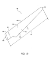
- a ring insert 100 (as indicated by the dotted lines) is disposed within the blade root section 104, and will be discussed in greater detail in regards to FIGS. 3-6 .
- the blade root section 104 has a span-wise extension portion 132 defined by an inner circumferential component 124 and outer circumferential component 122.
- the term "circumferential component” is used herein to encompass any material configuration that defines the separate three-dimensional structures of the components 122, 124, such as separate laminates. It should also be understood that the term “circumferential” is not limited to "cylindrical", but includes the presence of any type of structure that may affect the cross-sectional shape of the root circumferential components, such as surface corrugations or other surface characteristics.
- the inner 124 and outer 122 circumferential components are separated by the radial gap 136.
- a ring insert 100 is disposed in the radial gap 136 and bonded to the inner 124 and outer 122 circumferential components of the blade root section 104.
- the ring insert 100 has an inner circumferential surface 126 and an outer circumferential surface 128, wherein at least one of the inner 126 or outer 128 circumferential surfaces has a radially and/or span-wise varying cross-sectional profile that increases bonding surface contact area between the surfaces 126, 128 and the respective circumferential components 124, 122 as compared to a non-varying cross-sectional profile.
- both surfaces 126, 128 have a radially varying cross-sectional profile.
- either one or both of the surfaces 126, 128 may have a radially and/or span-wise varying cross-sectional profile.
- Such surfaces may contain a variety of undulating or corrugated patterns.
- the undulating pattern may be prismatic (squares, triangles, etc.), waves, semi-circles, or other suitable varying structure.
- the inner circumferential surface 126 may contain one undulating pattern, while the outer circumferential surface 128 may have a different undulating pattern.
- both the inner and outer circumferential surfaces 126, 128 may have the same undulating pattern. As illustrated in FIG. 3 (and shown in greater detail in FIG. 5 ), both the inner and outer circumferential surfaces 126, 128 have a wave-like undulating pattern, so as to coordinate with connecting means 102
- a connecting means 102 extends into the ring insert 100.
- the connecting means 102 may be a bolt or any suitable connecting device that secures the blade root section 104 to a pitch bearing 106 (not shown) and/or other wind turbine components.
- the connecting means 102 may be screwed into the ring insert 100 as per conventional means, where preload is intended to compress the ring insert 100 against the pitch bearing.
- FIGS. 4 and 5 a cross-sectional view and a top view of blade root section 104 and ring insert 100 according to certain embodiments are illustrated, respectively.
- the blade root section 104 is connected to a hub 20 with a plurality of bolts 102 through pitch bearing 106.
- the blade root section 104 has a span-wise end extension 132 defined by an inner circumferential component 124 and an outer circumferential component 122.
- the inner 124 and outer 122 circumferential components are separated by a radial gap 136. Further, the inner 124 and outer 122 circumferential components merge together at apex 130, thereby providing a single, solid structure.
- the outer circumferential component 122 defines a first wall thickness, W 1
- the inner circumferential component 124 defines a second wall thickness, W 2 .
- the first wall thickness may be greater than, less than, or equal to the second wall thickness.
- the first wall thickness and the second wall thickness are substantially equal.
- the ring insert 100 (made of one section or partitioned sections) is disposed in the radial gap 136 and bonded to the inner 124 and outer 122 circumferential components by any suitable bonding agent or material 144.
- the bonding agent 144 may be applied to both the inner 124 and outer 122 circumferential components and at the apex 130 or any combination thereof. Placing the bonding agent 144 at the surface of the insert ensures transfer of the load from the blade root to the pitch bearing.
- a transition material may be placed to attenuate the stiffness discontinuity between the ring insert 100 to the material making up the blade shells 104.
- the width of the radial gap 136 may vary from the end face 140 of the blade root section 104 to the apex 130.
- the width of the radial gap 136 may gradually decrease from the end face 140 of the root section 104 to the apex 130.
- the width of the radial gap 136 may be consistent from end face 140 to the apex 130.
- the ring insert 100 may be bonded within the blade root section 104 such that the end face 142 of the ring insert 100 is generally flush with the end face 140 of the root section 104, thereby providing a flush surface 120.
- Such a configuration provides maximum bonding surface contact area between the ring insert 100 and the blade root section 104, and other wind turbine components. Alternatively, it may not be flush with the blade root end face to preserve a metal-to-metal interface, thereby eliminating a compressive state in the laminate associated with the preload.
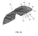
- the blade root section 104 includes inner 124 and outer 122 circumferential components defining a radial gap 136 therebetween.
- the ring insert 100 includes inner 126 and outer 128 circumferential surfaces, wherein each surface has a radially varying cross-sectional profile so as to increase bonding surface contact area between the inner 126 and outer 128 circumferential surfaces and the respective circumferential components (124 and 122, respectively) as compared to a constant radius cross-sectional profile.
- the inner and outer surfaces 126, 128 have a wave-like pattern.
- bolts 102 are circumferentially spaced (equally or otherwise) around the ring insert 100 and connect the blade root section 104 to a pitch bearing 106 ( FIG. 4 ).
- FIGS. 4 and 5 illustrate a ring insert 100 composed of a single segment of material; however, the ring insert 100 may also be composed of multiple segments connected together so as to provide a continuous ring insert.
- the ring insert 100 may be composed of two segments, one on the pressure side and one on the suction side of the blade root section 104.
- the blade root section 104 has a substantially circular cross-section, though any suitable cross-section may be employed.
- the ring insert 100 may be constructed of any suitable material (with appropriate surface finish) so as to provide sufficient bonding between the ring insert 100 and the blade root section 104.
- the ring insert 100 may be a fibrous/composite or metallic material or any combination thereof.
- the fibrous/composite material may be constructed of carbon fibers, glass fibers, natural fibers, or similar, or any combination thereof.
- the ring insert 100 may be constructed of a suitable metal, metal alloy, or any combination thereof.
- the ring insert 100 may be a solid or hollow material.
- the blade root section 104 has a span-wise end portion 132 defined by inner 124 and outer 122 circumferential components and separated by radial gap 136.
- the end portion 132 is attached to the pitch bearing 106 by bolt 102.
- the bolt 102 extends through the pitch bearing 106 and is disposed within the ring insert 100.
- the ring insert 100 is disposed in the radial gap 136 and bonded to the inner 124 and outer 122 circumferential components by a bonding agent 144. Placing the bonding agent 144 at the surface of the insert ensures transfer of the load from the blade root to the pitch bearing.
- a transition material may be placed to attenuate the stiffness discontinuity between the ring insert 100 to the material making up the blade shells 104.
- Any suitable bonding agent may be utilized, including a bonding paste or similar.
- the ring insert 100 includes inner 126 and outer 128 circumferential surfaces having a radially varying cross-sectional profile so as to increase a bonding surface contact area between the inner 126 and outer 128 circumferential surfaces and the respective circumferential components 124, 122 of the blade root section 104.
Applications Claiming Priority (1)
| Application Number | Priority Date | Filing Date | Title |
|---|---|---|---|
| US13/664,587 US20140119926A1 (en) | 2012-10-31 | 2012-10-31 | Wind turbine rotor blade assembly with a ring insert in the blade root |
Publications (2)
| Publication Number | Publication Date |
|---|---|
| EP2728171A2 true EP2728171A2 (de) | 2014-05-07 |
| EP2728171A3 EP2728171A3 (de) | 2018-04-11 |
Family
ID=49486368
Family Applications (1)
| Application Number | Title | Priority Date | Filing Date |
|---|---|---|---|
| EP13190534.1A Withdrawn EP2728171A3 (de) | 2012-10-31 | 2013-10-28 | Windturbinen-Rotorschaufelanordnung mit einem Ringeinsatz am Schaufelfuß |
Country Status (3)
| Country | Link |
|---|---|
| US (1) | US20140119926A1 (de) |
| EP (1) | EP2728171A3 (de) |
| CA (1) | CA2830128A1 (de) |
Cited By (4)
| Publication number | Priority date | Publication date | Assignee | Title |
|---|---|---|---|---|
| DE102014008558A1 (de) * | 2014-05-28 | 2015-12-03 | Windnovation Engineering Solutions Gmbh | Rotorblattanschluss |
| WO2017101944A1 (en) * | 2015-12-14 | 2017-06-22 | Vestas Wind Systems A/S | Joint for connecting a wind turbine rotor blade to a rotor hub and associated method |
| WO2020169393A1 (de) * | 2019-02-18 | 2020-08-27 | Wobben Properties Gmbh | Windenergieanlagen-komponente für einen windenergieanlagen-turm, windenergieanlagen-turm, rotorblatt, windenergieanlage und verfahren zur herstellung einer windenergieanlagen-komponente |
| WO2020193753A1 (de) * | 2019-03-28 | 2020-10-01 | Aero Dynamik Consult Gmbh | Anordnung, verfahren und werkzeug zum befestigen von bauteilen |
Families Citing this family (5)
| Publication number | Priority date | Publication date | Assignee | Title |
|---|---|---|---|---|
| EP2952738A1 (de) * | 2014-06-05 | 2015-12-09 | Siemens Aktiengesellschaft | Fußbuchse für einen Schaufelfuß einer Windturbinenrotorschaufel, eines Schaufelblatts, eines Windturbinenrotorblatts, Windturbine und Verfahren zur Herstellung einer Fußbuchse |
| US10190571B2 (en) * | 2015-07-01 | 2019-01-29 | General Electric Company | Ring insert for a wind turbine rotor blade |
| US10626847B2 (en) | 2017-01-05 | 2020-04-21 | General Electric Company | Method for manufacturing a wind turbine rotor blade root section with pultruded rods and associated wind turbine blade |
| US11015570B2 (en) * | 2017-03-01 | 2021-05-25 | General Electric Company | Wind turbine rotor blade root insert with integrated flange member |
| DE102021118608A1 (de) | 2021-07-19 | 2023-01-19 | Hawart Sondermaschinenbau Gmbh | Rotorblatt für eine Windkraftanlage sowie Verfahren und Vorrichtung zum Herstellen eines Flanscheinlegers für das Rotorblatt |
Family Cites Families (9)
| Publication number | Priority date | Publication date | Assignee | Title |
|---|---|---|---|---|
| NZ534196A (en) * | 2002-01-11 | 2005-12-23 | Fiberline As | A method of producing a fibre reinforced structural element |
| FR2863321A1 (fr) * | 2003-12-09 | 2005-06-10 | Ocea Sa | Pale d'aerogenerateur integrant des moyens de liaison ameliores entre la racine de la pale et le moyeu de l'aerogenerateur, bride, procede de fabrication et aerogenerateur correspondant |
| WO2006070171A1 (en) * | 2004-12-29 | 2006-07-06 | Vestas Wind Systems A/S | Method of manufacturing a wind turbine blade shell member with a fastening member and a wind turbine blade with a fastening member |
| EP2138716B2 (de) * | 2008-06-27 | 2024-02-14 | Siemens Gamesa Renewable Energy Innovation & Technology, S.L. | Klingeneinsatz |
| GB2472460B (en) * | 2009-08-07 | 2011-11-16 | Gurit | Wind or tidal turbine blade having an attachment |
| JP4939640B2 (ja) * | 2010-10-22 | 2012-05-30 | 三菱重工業株式会社 | 風車回転翼 |
| WO2012140039A2 (en) * | 2011-04-11 | 2012-10-18 | Lm Wind Power A/S | Wind turbine blade comprising circumferential retaining means in root regions |
| WO2012140049A2 (en) * | 2011-04-11 | 2012-10-18 | Lm Wind Power A/S | Wind turbine blade comprising cylindrical metal inserts in a root region thereof |
| EP2532881B1 (de) * | 2011-06-10 | 2014-12-17 | Siemens Aktiengesellschaft | Rotorblatt für eine Windturbine |
-
2012
- 2012-10-31 US US13/664,587 patent/US20140119926A1/en not_active Abandoned
-
2013
- 2013-10-17 CA CA2830128A patent/CA2830128A1/en not_active Abandoned
- 2013-10-28 EP EP13190534.1A patent/EP2728171A3/de not_active Withdrawn
Non-Patent Citations (1)
| Title |
|---|
| None |
Cited By (9)
| Publication number | Priority date | Publication date | Assignee | Title |
|---|---|---|---|---|
| DE102014008558A1 (de) * | 2014-05-28 | 2015-12-03 | Windnovation Engineering Solutions Gmbh | Rotorblattanschluss |
| DE102014008558B4 (de) | 2014-05-28 | 2019-09-12 | Windnovation Engineering Solutions Gmbh | Rotorblattanschluss |
| WO2017101944A1 (en) * | 2015-12-14 | 2017-06-22 | Vestas Wind Systems A/S | Joint for connecting a wind turbine rotor blade to a rotor hub and associated method |
| CN108713098A (zh) * | 2015-12-14 | 2018-10-26 | 维斯塔斯风力系统有限公司 | 用于将风轮机转子叶片连接至转子轮毂的接头及相关方法 |
| CN108713098B (zh) * | 2015-12-14 | 2020-04-17 | 维斯塔斯风力系统有限公司 | 用于将风轮机转子叶片连接至转子轮毂的接头及相关方法 |
| US11319922B2 (en) | 2015-12-14 | 2022-05-03 | Vestas Wind Systems A/S | Joint for connecting a wind turbine rotor blade to a rotor hub and associated method |
| WO2020169393A1 (de) * | 2019-02-18 | 2020-08-27 | Wobben Properties Gmbh | Windenergieanlagen-komponente für einen windenergieanlagen-turm, windenergieanlagen-turm, rotorblatt, windenergieanlage und verfahren zur herstellung einer windenergieanlagen-komponente |
| WO2020193753A1 (de) * | 2019-03-28 | 2020-10-01 | Aero Dynamik Consult Gmbh | Anordnung, verfahren und werkzeug zum befestigen von bauteilen |
| US11976625B2 (en) | 2019-03-28 | 2024-05-07 | Adc Connection Solutions Gmbh | Assembly, method, and tool for securing components |
Also Published As
| Publication number | Publication date |
|---|---|
| US20140119926A1 (en) | 2014-05-01 |
| EP2728171A3 (de) | 2018-04-11 |
| CA2830128A1 (en) | 2014-04-30 |
Similar Documents
| Publication | Publication Date | Title |
|---|---|---|
| EP2728171A2 (de) | Windturbinen-Rotorschaufelanordnung mit einem Ringeinsatz am Schaufelfuß | |
| US9464622B2 (en) | Rotor blade assembly having a stiffening root insert | |
| US10190571B2 (en) | Ring insert for a wind turbine rotor blade | |
| US8025485B2 (en) | Wind turbine blade attachment configuration with flattened bolts | |
| EP2634417B1 (de) | Schaufeleinsatz für eine Windturbinenlaufschaufel | |
| US20120141287A1 (en) | Wind turbine rotor blade joint | |
| US8066490B2 (en) | Wind turbine rotor blade | |
| US8622707B2 (en) | Root attachment for a rotor blade assembly | |
| US9920739B2 (en) | System and method for securing a conductive cable within a wind turbine rotor blade | |
| US20130219718A1 (en) | Blade insert for a wind turbine rotor blade and related methods | |
| EP2249027A2 (de) | Segmentiertes Rotorblatt einer Windenergieanlage | |
| US8360732B2 (en) | Rotor blade section and method for assembling a rotor blade for a wind turbine | |
| EP2868916A1 (de) | Sehnenverlängerungen für eine Windturbinenrotorblattanordnung | |
| US20120027588A1 (en) | Root flap for rotor blade in wind turbine | |
| US10570879B2 (en) | Joint assembly for a wind turbine rotor blade with flanged bushings | |
| US20120027615A1 (en) | Rotor blade | |
| US9039380B2 (en) | Winglet for a wind turbine rotor blade | |
| EP2746572A2 (de) | Wurzelanordnungen mit externen strukturellen Verbindungsträgerstrukturen für Rotorblätter | |
| US20150093250A1 (en) | Root stiffener assembly for a wind turbine rotor blade | |
| EP3874142B1 (de) | Segmentiertes rotorblatt einer windturbine mit einem hohlen, sich in sehnenrichtung erstreckenden stift | |
| US20120027618A1 (en) | Angled blade root | |
| US20120027611A1 (en) | Compression member for wind turbine rotor blades | |
| US20130064677A1 (en) | Rotor blade assembly for wind turbine | |
| US9664174B2 (en) | Aerodynamic root adapters for wind turbine rotor blades |
Legal Events
| Date | Code | Title | Description |
|---|---|---|---|
| PUAI | Public reference made under article 153(3) epc to a published international application that has entered the european phase |
Free format text: ORIGINAL CODE: 0009012 |
|
| 17P | Request for examination filed |
Effective date: 20131028 |
|
| AK | Designated contracting states |
Kind code of ref document: A2 Designated state(s): AL AT BE BG CH CY CZ DE DK EE ES FI FR GB GR HR HU IE IS IT LI LT LU LV MC MK MT NL NO PL PT RO RS SE SI SK SM TR |
|
| AX | Request for extension of the european patent |
Extension state: BA ME |
|
| PUAL | Search report despatched |
Free format text: ORIGINAL CODE: 0009013 |
|
| AK | Designated contracting states |
Kind code of ref document: A3 Designated state(s): AL AT BE BG CH CY CZ DE DK EE ES FI FR GB GR HR HU IE IS IT LI LT LU LV MC MK MT NL NO PL PT RO RS SE SI SK SM TR |
|
| AX | Request for extension of the european patent |
Extension state: BA ME |
|
| RIC1 | Information provided on ipc code assigned before grant |
Ipc: F03D 1/06 20060101AFI20180306BHEP |
|
| STAA | Information on the status of an ep patent application or granted ep patent |
Free format text: STATUS: REQUEST FOR EXAMINATION WAS MADE |
|
| 17P | Request for examination filed |
Effective date: 20181011 |
|
| RBV | Designated contracting states (corrected) |
Designated state(s): AL AT BE BG CH CY CZ DE DK EE ES FI FR GB GR HR HU IE IS IT LI LT LU LV MC MK MT NL NO PL PT RO RS SE SI SK SM TR |
|
| STAA | Information on the status of an ep patent application or granted ep patent |
Free format text: STATUS: THE APPLICATION IS DEEMED TO BE WITHDRAWN |
|
| 18D | Application deemed to be withdrawn |
Effective date: 20181012 |
|
| P01 | Opt-out of the competence of the unified patent court (upc) registered |
Effective date: 20230522 |