EP2727822A2 - Aircraft having a recessed cavity in an aft pressure bulkhead wall surface and a galley moved rearwardly into the recessed cavity increasing floor space in front of the galley - Google Patents
Aircraft having a recessed cavity in an aft pressure bulkhead wall surface and a galley moved rearwardly into the recessed cavity increasing floor space in front of the galley Download PDFInfo
- Publication number
- EP2727822A2 EP2727822A2 EP13191824.5A EP13191824A EP2727822A2 EP 2727822 A2 EP2727822 A2 EP 2727822A2 EP 13191824 A EP13191824 A EP 13191824A EP 2727822 A2 EP2727822 A2 EP 2727822A2
- Authority
- EP
- European Patent Office
- Prior art keywords
- aircraft
- galley
- wall surface
- pressure bulkhead
- aft
- Prior art date
- Legal status (The legal status is an assumption and is not a legal conclusion. Google has not performed a legal analysis and makes no representation as to the accuracy of the status listed.)
- Granted
Links
Images



Classifications
-
- B—PERFORMING OPERATIONS; TRANSPORTING
- B64—AIRCRAFT; AVIATION; COSMONAUTICS
- B64C—AEROPLANES; HELICOPTERS
- B64C1/00—Fuselages; Constructional features common to fuselages, wings, stabilising surfaces or the like
- B64C1/06—Frames; Stringers; Longerons ; Fuselage sections
- B64C1/10—Bulkheads
-
- B—PERFORMING OPERATIONS; TRANSPORTING
- B64—AIRCRAFT; AVIATION; COSMONAUTICS
- B64D—EQUIPMENT FOR FITTING IN OR TO AIRCRAFT; FLIGHT SUITS; PARACHUTES; ARRANGEMENT OR MOUNTING OF POWER PLANTS OR PROPULSION TRANSMISSIONS IN AIRCRAFT
- B64D11/00—Passenger or crew accommodation; Flight-deck installations not otherwise provided for
- B64D11/04—Galleys
-
- Y—GENERAL TAGGING OF NEW TECHNOLOGICAL DEVELOPMENTS; GENERAL TAGGING OF CROSS-SECTIONAL TECHNOLOGIES SPANNING OVER SEVERAL SECTIONS OF THE IPC; TECHNICAL SUBJECTS COVERED BY FORMER USPC CROSS-REFERENCE ART COLLECTIONS [XRACs] AND DIGESTS
- Y02—TECHNOLOGIES OR APPLICATIONS FOR MITIGATION OR ADAPTATION AGAINST CLIMATE CHANGE
- Y02T—CLIMATE CHANGE MITIGATION TECHNOLOGIES RELATED TO TRANSPORTATION
- Y02T50/00—Aeronautics or air transport
- Y02T50/40—Weight reduction
Definitions
- the present invention pertains to an aircraft cabin that has been reconfigured to increase the floor space of the aircraft cabin.
- the present invention pertains to an aircraft cabin having a rear fuselage galley and a modified rear bulkhead that enables the galley to be moved rearwardly to provide additional floor space inside the cabin.
- the present invention provides an aircraft comprising:
- the aircraft of the present invention overcomes the disadvantages associated with prior art aircraft having galleys that project into a cross aisle as discussed above. This is accomplished by reconfiguring the aft pressure bulkhead of the aircraft to enable the galley of the aircraft to be moved rearwardly of the cross aisle. This increases the floor space of the aircraft
- the aft pressure bulkhead of the aircraft of the invention is redesigned with a recessed cavity in a central area of the bulkhead.
- the recessed cavity is aligned with the galley of the aircraft cabin and is dimensioned to receive portions of the galley. This enables the galley to be positioned rearwardly of the cross aisle and rearwardly of the boarding doors at the laterally opposite ends of the cross aisle.
- the galley being moved rearwardly of the cross aisle provides clear access to the two boarding doors at the opposite ends of the cross aisle and increases the floor space of the aircraft.
- the aircraft further comprises a plurality of vertically oriented members attached to the wall, the members having a plurality of non-vertical support members interconnecting the vertical members wherein at least one pair of vertical members and one pair of non-vertical support members define a volume sufficient to accept a portion of a galley cart.
- non-vertical support members are substantially orthogonal to the vertical members.
- the wall is positioned on an aft side of the support members, the wall being substantially flat across its area.
- the wall is substantially flat across its area.
- the wall is continuous across its area and extends orthogonally between support members, the wall defining a volume between the support members the volume sufficient to accept a portion of a galley cart.
- the aircraft further comprises a galley cart located in the volume between the support members and on the floor surface that extends between the support members.
- the aircraft further comprises the aft pressure bulkhead having a continuous wall surface having cavities defining a volume between the support members, the wall positioned adjacent to the galley.
- the galley has a floor surface that extends into the cavities.
- the aircraft comprises a pair of aft most boarding doorways in laterally opposite sides of the rear of the aircraft fuselage; and, the galley cart compartment being positioned entirely rearwardly of the pair of aft most boarding doorways.
- the aircraft further comprises a wall surface being a continuous surface supported by a plurality of structural beams, the structural beams being positioned such that at least two are at least 12 inches apart and connected by two cross beams that are at least 40 inches apart.
- the wall surface is the aforementioned wall or continuous wall surface.
- the galley has a pair of galley walls on laterally opposite sides of the galley with rearward portions of the pair of galley walls extending rearwardly through the aft pressure bulkhead forward wall surface and forming laterally opposite sides of the recessed cavity in the aft pressure bulkhead forward wall surface.
- an aircraft comprising: an aircraft fuselage containing an aircraft cabin, the aircraft fuselage having a longitudinal length between a front of the aircraft fuselage and a rear of the aircraft fuselage, the aircraft cabin having a longitudinal length between a front of the aircraft cabin and a rear of the aircraft cabin, and the aircraft cabin having a lateral width between laterally opposite first and second outboard sidewalls of the aircraft cabin; a floor surface in the aircraft cabin; a galley in the rear of the aircraft cabin; and, an aft pressure bulkhead at the rear of the aircraft cabin, the aft pressure bulkhead including a forward wall surface facing toward the aircraft cabin and extending laterally across the rear of the aircraft cabin between the first and second outboard sidewalls of the aircraft cabin, and the forward wall surface having a recessed cavity in a central area of the forward wall surface and above the floor surface, the cavity extending rearwardly of the forward wall surface and forming a portion of the galley.
- the galley includes a galley cart compartment containing at least one galley cart, the galley cart being supported on the floor surface and inserted longitudinally into the galley cart compartment, and at least a portion of the galley cart compartment extending into the recessed cavity in the central area of the forward wall surface.
- a portion of the galley cart in the galley cart compartment extends rearwardly into the recessed cavity in the aft pressure bulkhead forward wall surface.
- the aft pressure bulkhead is a rigid, pressure sealed structure with vertical beams supporting the aft pressure bulkhead forward wall surface, and the recessed cavity extends rearwardly between a pair of the vertical beams supporting the aft pressure bulkhead forward wall surface.
- the present invention provides a method of increasing the floor space in an aircraft cabin comprising:
- the method further comprises extending the floor space rearwardly of the aft pressure bulkhead wall surface.
- the method further comprises temporarily positioning a galley cart in the recessed cavity with a portion of the galley cart extending rearwardly of the aft pressure bulkhead wall surface.
- the method further comprises supporting the aft pressure bulkhead wall surface with vertical beams and positioning the recessed cavity between a pair of the vertical beams.
- Figure 1 is a representation of the floor plan at the rear of the aircraft of the invention with the repositioned galley of the invention.
- the aircraft cabin has a longitudinal length between a front 14 of the cabin and a rear 16 of the cabin.
- the cabin also has a lateral width between opposite first 18 and second 22 outboard sidewalls of the cabin.
- a plurality of rows of seats 24, 26 are arranged on the floor surface 28 of the aircraft cabin.
- the rows of seats 24, 26 are arranged on laterally opposite sides of the cabin and define a central aisle 32.
- the aisle 32 extends longitudinally through the cabin across the floor surface 28 between the front 14 and rear 16 of the cabin and between the rows of seats 24, 26. Although only one aisle is shown extending the length of the cabin, there could be multiple aisles separating the rows of seats and extending through the length of the cabin.
- a cross aisle 36 extends laterally across the rear 16 of the cabin.
- the cross aisle 36 may extend between a pair of aft most boarding doorways 38, 42 in the respective first 18 and second 22 sidewalls of the aircraft cabin.
- the aisle 32 extending between the rows of seats 24, 26 intersects the cross aisle 36.
- the aircraft may be provided with a modified aft pressure bulkhead 44.
- the bulkhead 44 may include a pressure wall and a interconnected support structure configured to attach to the aircraft fuselage barrel.
- the pressure wall surface 46 may be continuous and extend vertically upwardly from the floor surface 28 and laterally across the rear of the aircraft cabin between the first 18 and second 22 outboard sidewalls of the aircraft cabin.
- the aft pressure bulkhead 44 may comprise a plurality of vertically oriented support members or beams 48 that are secured to the top and bottom of the aircraft fuselage, and a plurality of horizontally oriented support members or beams 52 that are secured to the opposite sides of the aircraft fuselage.
- the interconnecting beams 48, 52 shown in Figure 2 are also secured together, forming a rigid structural framework of the aft pressure bulkhead 44.
- the pressure wall 46 is preferably attached to the interconnected support structure to form a rigid pressure wall structure.
- the vertically oriented beams 48 may be spaced approximately 12 inches from each other.
- a lower horizontal beam 54 and a horizontal beam 56 immediately above the lower beam are spaced approximately 40 inches from each other. This spacing of the vertical beams 48 and the bottom two horizontal beams 54, 56 defines four upright rectangular, voids or volumes between the beams.
- the spacing distances between the beams could be varied and the number of voids left between the beams could be varied.
- the pressure wall surface 46 of the bulkhead has been modified with a large recessed chamber or cavity that extends rearwardly through a plane of the wall surface.
- the cavities 58, 62, 64, 66 extend rearwardly through a plane of the forward wall surface 46 to respective back walls 68, 72, 74, 76 of the cavities.
- Each of the cavities 58, 62, 64, 66 has the general upright rectangular orientation of the voids between the beams 48, 52 of the aft pressure bulkhead 44.
- the lateral sides of the cavities 58, 62, 64, 66 are defined by vertically oriented galley walls 78, 82, 84, 86, 88 that are comprised of portions of the vertical beams 48 of the bulkhead 44.
- the cavities 58, 62, 64, 66 are formed in the forward wall surface 46 of the aft pressure bulkhead 44 without compromising the structural integrity of the aft pressure bulkhead.
- the cavities 58, 62, 64, 66 are formed in a central area of the wall surface 46 just above the floor surface 28 of the aircraft cabin.
- a top panel 90 compromising one of the horizontal beams 56 extends over the cavities and a portion of the floor surface 92 extends rearwardly of the wall surface 46 and into the cavities 58, 62, 64, 66.
- the cavities 58, 62, 64,66 thereby increase the floor surface of the aircraft.
- the cavities 58, 62, 64, 66 are longitudinally aligned with a galley 92 of the aircraft cabin.
- the dimensions of the cavities 58, 62, 64, 66 correspond with those of galley cart compartments 94, 96, 98, 102 of the galley 92.
- the cavities 58, 62, 64, 66 are dimensioned to receive rearward portions of four galley carts 104, 106,108, 112 that are rolled on the floor surfaces 28, 90 and into the cavities. This enables the galley 92 to be moved rearwardly in the aircraft cabin rear 16 increasing floor space in front of the galley.
- the galley 92 is positioned entirely rearwardly of the cross-aisle 36 and the aft most boarding doorways 38, 42 at the laterally opposite ends of the cross-aisle.
- the rearward extension of the galley 92 into the cavities 58, 62, 64, 66 of the modified aft pressure bulkhead 44 increases the floor space 28 of the aircraft cabin and improves passenger access to the aft most boarding doors 38, 48 of the aircraft.
- the galley may further include a wall that extends adjacent to the aft bulkhead and extends into the cavities of the bulkhead.
- the wall surface could be a rearward wall surface supported on the bulkhead beams 48, 52 behind the vertically oriented beams and horizontally oriented beams.
- the wall may be substantially flat and continuous across the bulkhead area while the beams remain spaced apart to provide the needed volume for extending the floor space and positioning the galley carts.
Landscapes
- Engineering & Computer Science (AREA)
- Aviation & Aerospace Engineering (AREA)
- Mechanical Engineering (AREA)
- Body Structure For Vehicles (AREA)
- Tires In General (AREA)
- Steps, Ramps, And Handrails (AREA)
- Residential Or Office Buildings (AREA)
Abstract
Description
- The present invention pertains to an aircraft cabin that has been reconfigured to increase the floor space of the aircraft cabin. In particular, the present invention pertains to an aircraft cabin having a rear fuselage galley and a modified rear bulkhead that enables the galley to be moved rearwardly to provide additional floor space inside the cabin.
- Commercial aircraft set up for the transportation of passengers typically include rows of seats along the length of the aircraft cabin and one or more aisles that extend the length of the aircraft between the rows of seats. Some aircraft have a cross aisle at the rear of the aircraft that extends between a pair of boarding doorways in the opposite sides of the aircraft and a galley at the rear of the aircraft adjacent the cross aisle. The traditional positioning of the galley in the aircraft cabin often requires that a portion of the galley project out into the cross aisle of the aircraft cabin. Thus, the galley can prove to be an impediment to passengers comfortably moving along the cross aisle when boarding or exiting the aircraft.
- In a first aspect, the present invention provides an aircraft comprising:
- a fuselage having a cabin and a galley in a rear of the cabin;
- an aft pressure bulkhead at a rear of the aircraft fuselage, the aft pressure bulkhead including a wall extending laterally across the rear of the aircraft fuselage between first and second outboard sidewalls of the cabin, and at least two support members extending vertically and separated by a non-vertical support member, the vertical and horizontal support members defining a volume sufficient to accept a portion of a galley cart.
- The aircraft of the present invention overcomes the disadvantages associated with prior art aircraft having galleys that project into a cross aisle as discussed above. This is accomplished by reconfiguring the aft pressure bulkhead of the aircraft to enable the galley of the aircraft to be moved rearwardly of the cross aisle. This increases the floor space of the aircraft
- The aft pressure bulkhead of the aircraft of the invention is redesigned with a recessed cavity in a central area of the bulkhead. The recessed cavity is aligned with the galley of the aircraft cabin and is dimensioned to receive portions of the galley. This enables the galley to be positioned rearwardly of the cross aisle and rearwardly of the boarding doors at the laterally opposite ends of the cross aisle. The galley being moved rearwardly of the cross aisle provides clear access to the two boarding doors at the opposite ends of the cross aisle and increases the floor space of the aircraft.
- Preferably the aircraft further comprises a plurality of vertically oriented members attached to the wall, the members having a plurality of non-vertical support members interconnecting the vertical members wherein at least one pair of vertical members and one pair of non-vertical support members define a volume sufficient to accept a portion of a galley cart.
- Preferably the non-vertical support members are substantially orthogonal to the vertical members.
- Preferably the wall is positioned on an aft side of the support members, the wall being substantially flat across its area.
- Preferably the wall is substantially flat across its area.
- Preferably the wall is continuous across its area and extends orthogonally between support members, the wall defining a volume between the support members the volume sufficient to accept a portion of a galley cart.
- Preferably the aircraft further comprises a galley cart located in the volume between the support members and on the floor surface that extends between the support members.
- Preferably the aircraft further comprises the aft pressure bulkhead having a continuous wall surface having cavities defining a volume between the support members, the wall positioned adjacent to the galley.
- Preferably the galley has a floor surface that extends into the cavities.
- Preferably the aircraft comprises a pair of aft most boarding doorways in laterally opposite sides of the rear of the aircraft fuselage; and,
the galley cart compartment being positioned entirely rearwardly of the pair of aft most boarding doorways. - Preferably, the aircraft further comprises a wall surface being a continuous surface supported by a plurality of structural beams, the structural beams being positioned such that at least two are at least 12 inches apart and connected by two cross beams that are at least 40 inches apart. Preferably the wall surface is the aforementioned wall or continuous wall surface.
- Preferably the galley has a pair of galley walls on laterally opposite sides of the galley with rearward portions of the pair of galley walls extending rearwardly through the aft pressure bulkhead forward wall surface and forming laterally opposite sides of the recessed cavity in the aft pressure bulkhead forward wall surface.
- According to another aspect of the present disclosure there is provided an aircraft comprising: an aircraft fuselage containing an aircraft cabin, the aircraft fuselage having a longitudinal length between a front of the aircraft fuselage and a rear of the aircraft fuselage, the aircraft cabin having a longitudinal length between a front of the aircraft cabin and a rear of the aircraft cabin, and the aircraft cabin having a lateral width between laterally opposite first and second outboard sidewalls of the aircraft cabin; a floor surface in the aircraft cabin; a galley in the rear of the aircraft cabin; and, an aft pressure bulkhead at the rear of the aircraft cabin, the aft pressure bulkhead including a forward wall surface facing toward the aircraft cabin and extending laterally across the rear of the aircraft cabin between the first and second outboard sidewalls of the aircraft cabin, and the forward wall surface having a recessed cavity in a central area of the forward wall surface and above the floor surface, the cavity extending rearwardly of the forward wall surface and forming a portion of the galley.
- Preferably the galley includes a galley cart compartment containing at least one galley cart, the galley cart being supported on the floor surface and inserted longitudinally into the galley cart compartment, and at least a portion of the galley cart compartment extending into the recessed cavity in the central area of the forward wall surface.
- Preferably a portion of the galley cart in the galley cart compartment extends rearwardly into the recessed cavity in the aft pressure bulkhead forward wall surface.
- Preferably the aft pressure bulkhead is a rigid, pressure sealed structure with vertical beams supporting the aft pressure bulkhead forward wall surface, and the recessed cavity extends rearwardly between a pair of the vertical beams supporting the aft pressure bulkhead forward wall surface.
- In a second aspect, the present invention provides a method of increasing the floor space in an aircraft cabin comprising:
- positioning an aft pressure bulkhead at a rear of the aircraft cabin, the aft pressure bulkhead having a front wall surface extending across the aircraft cabin and extending upwardly from a floor surface of the aircraft cabin, the bulkhead having;
- a recessed cavity in the wall surface, the recessed cavity extending rearwardly into the wall surface; and,
- positioning the floor surface into the recessed cavity.
- Preferably the method further comprises extending the floor space rearwardly of the aft pressure bulkhead wall surface.
- Preferably the method further comprises temporarily positioning a galley cart in the recessed cavity with a portion of the galley cart extending rearwardly of the aft pressure bulkhead wall surface.
- Preferably the method further comprises supporting the aft pressure bulkhead wall surface with vertical beams and positioning the recessed cavity between a pair of the vertical beams.
- The features, functions, and advantages that have been discussed can be achieved independently in various embodiments or may be combined in yet other embodiments, further details of which can be seen with reference to the following description and drawings.
-
-
Figure 1 is a representation of the floor plan at the rear of the aircraft of the invention with the repositioned galley of the invention. -
Figure 2 is a partial perspective view of the aft pressure bulkhead of the invention and the floor surface of the aircraft cabin. -
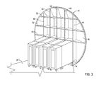
Figure 3 is a view similar toFigure 2 , but showing galley carts inserted into the recessed cavity in the aft pressure bulkhead. -
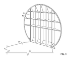
Figure 4 is a partial perspective view of the aft pressure bulkhead of the invention and the floor surface of the aircraft cabin. -
Figure 5 is a flow chart representing a method of providing a recessed cavity in an aft pressure bulkhead to increase the floor space of an aircraft. -
Figure 1 is a representation of the floor plan at the rear of the aircraft of the invention with the repositioned galley of the invention. The aircraft cabin has a longitudinal length between afront 14 of the cabin and a rear 16 of the cabin. The cabin also has a lateral width between opposite first 18 and second 22 outboard sidewalls of the cabin. - A plurality of rows of
seats floor surface 28 of the aircraft cabin. The rows ofseats central aisle 32. Theaisle 32 extends longitudinally through the cabin across thefloor surface 28 between thefront 14 and rear 16 of the cabin and between the rows ofseats - A
cross aisle 36 extends laterally across the rear 16 of the cabin. Thecross aisle 36 may extend between a pair of aftmost boarding doorways aisle 32 extending between the rows ofseats cross aisle 36. Thus, passengers boarding and exiting the aircraft through theaft boarding doorways central aisle 32 andcross aisle 36. - The aircraft may be provided with a modified
aft pressure bulkhead 44. Thebulkhead 44 may include a pressure wall and a interconnected support structure configured to attach to the aircraft fuselage barrel. In a preferred embodiment thepressure wall surface 46 may be continuous and extend vertically upwardly from thefloor surface 28 and laterally across the rear of the aircraft cabin between the first 18 and second 22 outboard sidewalls of the aircraft cabin. Referring toFigure 2 , theaft pressure bulkhead 44 may comprise a plurality of vertically oriented support members or beams 48 that are secured to the top and bottom of the aircraft fuselage, and a plurality of horizontally oriented support members or beams 52 that are secured to the opposite sides of the aircraft fuselage. The interconnecting beams 48, 52 shown inFigure 2 are also secured together, forming a rigid structural framework of theaft pressure bulkhead 44. Thepressure wall 46 is preferably attached to the interconnected support structure to form a rigid pressure wall structure. The vertically orientedbeams 48 may be spaced approximately 12 inches from each other. A lowerhorizontal beam 54 and ahorizontal beam 56 immediately above the lower beam are spaced approximately 40 inches from each other. This spacing of thevertical beams 48 and the bottom twohorizontal beams - As shown in
Figure 3 , thepressure wall surface 46 of the bulkhead has been modified with a large recessed chamber or cavity that extends rearwardly through a plane of the wall surface. Thecavities forward wall surface 46 torespective back walls cavities beams aft pressure bulkhead 44. The lateral sides of thecavities galley walls vertical beams 48 of thebulkhead 44. Thus, thecavities forward wall surface 46 of theaft pressure bulkhead 44 without compromising the structural integrity of the aft pressure bulkhead.
Thecavities wall surface 46 just above thefloor surface 28 of the aircraft cabin. As shown inFigure 2 , atop panel 90 compromising one of thehorizontal beams 56 extends over the cavities and a portion of thefloor surface 92 extends rearwardly of thewall surface 46 and into thecavities cavities
Referring toFigure 2 , thecavities galley 92 of the aircraft cabin. The dimensions of thecavities galley 92. As shown inFigure 3 , thecavities galley carts 104, 106,108, 112 that are rolled on the floor surfaces 28, 90 and into the cavities. This enables thegalley 92 to be moved rearwardly in the aircraft cabin rear 16 increasing floor space in front of the galley. Thegalley 92 is positioned entirely rearwardly of the cross-aisle 36 and the aftmost boarding doorways - The rearward extension of the
galley 92 into thecavities aft pressure bulkhead 44 increases thefloor space 28 of the aircraft cabin and improves passenger access to the aftmost boarding doors - In a further embodiment of aft pressure bulkhead as shown in
Figure 4 , the wall surface could be a rearward wall surface supported on the bulkhead beams 48, 52 behind the vertically oriented beams and horizontally oriented beams. In this configuration the wall may be substantially flat and continuous across the bulkhead area while the beams remain spaced apart to provide the needed volume for extending the floor space and positioning the galley carts. - As various modifications could be made in the construction of the invention herein described and illustrated without departing from the scope of the invention, it is intended that all matter contained in the foregoing description or shown in the accompanying drawings shall be interpreted as illustrative rather than limiting. Thus, the breadth and scope of the present invention should not be limited by any of the above described exemplary embodiments, but should be defined only in accordance with the following claims appended hereto and their equivalents.
Claims (15)
- An aircraft comprising:a fuselage having a cabin and a galley in a rear of the cabin;an aft pressure bulkhead at a rear of the aircraft fuselage, the aft pressure bulkhead including a wall extending laterally across the rear of the aircraft fuselage between first and second outboard sidewalls of the cabin, and at least two support members extending vertically and separated by a non-vertical support member, the vertical and horizontal support members defining a volume sufficient to accept a portion of a galley cart.
- The aircraft of claim 1 further comprising a plurality of vertically oriented members attached to the wall, the members having a plurality of non-vertical support members interconnecting the vertical members wherein at least one pair of vertical members and one pair of non-vertical support members define a volume sufficient to accept a portion of a galley cart.
- The aircraft of any previous claim wherein the wall is positioned on an aft side of the support members, the wall being substantially flat across its area.
- The aircraft of any previous claim wherein the wall is substantially flat across its area.
- The aircraft of any previous claim wherein the wall is continuous across its area and extends orthogonally between support members, the wall defining a volume between the support members the volume sufficient to accept a portion of a galley cart.
- The aircraft of any previous claim further comprising a galley cart located in the volume between the support members and on the floor surface that extends between the support members.
- The aircraft of any previous claim further comprising the aft pressure bulkhead having a continuous wall surface having cavities defining a volume between the support members, the wall positioned adjacent to the galley.
- The aircraft of any previous claim further comprising the galley having a floor surface that extends into the cavities.
- The aircraft of any previous claim, further comprising:a pair of aft most boarding doorways in laterally opposite sides of the rear of the aircraft fuselage; and,the galley cart compartment being positioned entirely rearwardly of the pair of aft most boarding doorways.
- The aircraft of any previous claim further comprising:a wall surface being a continuous surface supported by a plurality of structural beams,the structural beams being positioned such that at least two are at least 12 inches apart and connected by two cross beams that are at least 40 inches apart.
- The aircraft of any previous claim, further comprising:the galley having a pair of galley walls on laterally opposite sides of the galley with rearward portions of the pair of galley walls extending rearwardly through the aft pressure bulkhead forward wall surface and forming laterally opposite sides of the recessed cavity in the aft pressure bulkhead forward wall surface.
- A method of increasing the floor space in an aircraft cabin comprising:positioning an aft pressure bulkhead at a rear of the aircraft cabin, the aft pressure bulkhead having a front wall surface extending across the aircraft cabin and extending upwardly from a floor surface of the aircraft cabin, the bulkhead having;a recessed cavity in the wall surface, the recessed cavity extending rearwardly into the wall surface; and,positioning the floor surface into the recessed cavity.
- The method of claim 12, further comprising:extending the floor space rearwardly of the aft pressure bulkhead wall surface.
- The method of claim 12 or claim 13, further comprising:temporarily positioning a galley cart in the recessed cavity with a portion of the galley cart extending rearwardly of the aft pressure bulkhead wall surface.
- The method of any one of claims 12 to 14, further comprising:supporting the aft pressure bulkhead wall surface with vertical beams and positioning the recessed cavity between a pair of the vertical beams.
Applications Claiming Priority (1)
| Application Number | Priority Date | Filing Date | Title |
|---|---|---|---|
| US13/669,850 US9108716B2 (en) | 2012-11-06 | 2012-11-06 | Aircraft having a recessed cavity in an aft pressure bulkhead wall surface and a galley moved rearwardly into the recessed cavity increasing floor space in front of the galley |
Publications (3)
| Publication Number | Publication Date |
|---|---|
| EP2727822A2 true EP2727822A2 (en) | 2014-05-07 |
| EP2727822A3 EP2727822A3 (en) | 2017-12-13 |
| EP2727822B1 EP2727822B1 (en) | 2020-03-11 |
Family
ID=49554049
Family Applications (1)
| Application Number | Title | Priority Date | Filing Date |
|---|---|---|---|
| EP13191824.5A Active EP2727822B1 (en) | 2012-11-06 | 2013-11-06 | Aircraft having a recessed cavity in an aft pressure bulkhead wall surface and a galley moved rearwardly into the recessed cavity increasing floor space in front of the galley |
Country Status (5)
| Country | Link |
|---|---|
| US (2) | US9108716B2 (en) |
| EP (1) | EP2727822B1 (en) |
| JP (1) | JP6342642B2 (en) |
| CN (1) | CN103803055B (en) |
| ES (1) | ES2786110T3 (en) |
Cited By (6)
| Publication number | Priority date | Publication date | Assignee | Title |
|---|---|---|---|---|
| EP3075650A1 (en) * | 2015-03-30 | 2016-10-05 | Airbus Operations GmbH | Large self-carrying monument assembly for an aircraft and an aircraft having such a monument assembly |
| FR3049927A1 (en) * | 2016-04-07 | 2017-10-13 | Airbus Operations Sas | AIRCRAFT TRONCON COMPRISING A PRESSURIZATION PARTITION |
| FR3049928A1 (en) * | 2016-04-07 | 2017-10-13 | Airbus Operations Sas | AIRCRAFT TRONCON COMPRISING A VERTICAL BEAM PLANE PRESSURIZATION FENCE |
| EP3498604A1 (en) * | 2017-12-15 | 2019-06-19 | Airbus Americas, Inc. | Partition wall in cabin of aircraft supporting monuments |
| CN111017225A (en) * | 2019-12-13 | 2020-04-17 | 中国航空工业集团公司西安飞机设计研究所 | Inner decorative board for passenger cabin side wall of civil aircraft |
| EP3750792A1 (en) * | 2019-06-14 | 2020-12-16 | Airbus Americas, Inc. | Standard cabin monument sub-structure |
Families Citing this family (11)
| Publication number | Priority date | Publication date | Assignee | Title |
|---|---|---|---|---|
| US9896212B2 (en) | 2012-02-14 | 2018-02-20 | C&D Zodiac, Inc. | Integrated centerline lavatory galley monument |
| US9527591B2 (en) | 2012-02-14 | 2016-12-27 | C&D Zodiac, Inc. | Modular lavatory with alcove |
| US9108716B2 (en) * | 2012-11-06 | 2015-08-18 | The Boeing Company | Aircraft having a recessed cavity in an aft pressure bulkhead wall surface and a galley moved rearwardly into the recessed cavity increasing floor space in front of the galley |
| US9643724B2 (en) * | 2013-09-11 | 2017-05-09 | Driessen Aerospace Group N.V. | Aircraft galley configuration |
| DE102014107404A1 (en) | 2014-05-26 | 2015-11-26 | Airbus Operations Gmbh | Pressure bulkhead for a fuselage |
| WO2016049064A1 (en) * | 2014-09-22 | 2016-03-31 | C&D Zodiac, Inc. | Integrated centerline lavatory galley monument |
| EP3059156B1 (en) * | 2015-02-23 | 2020-04-01 | Airbus Operations, S.L. | Flat kinked rear pressure bulkhead |
| US10259582B2 (en) * | 2015-08-26 | 2019-04-16 | B/E Aerospace, Inc. | Aircraft cabin arrangement with optimized passenger and crew service areas |
| DE102015116804A1 (en) | 2015-10-02 | 2017-04-06 | Airbus Operations Gmbh | Space-efficient cabin segment for a vehicle and a passenger cabin with a plurality of seats and such a cabin segment |
| CN115571339A (en) * | 2022-11-08 | 2023-01-06 | 中国商用飞机有限责任公司 | The aircraft with the integrated layout of the cockpit of the escort cabin |
| EP4596394A1 (en) * | 2024-01-30 | 2025-08-06 | Airbus Operations GmbH | Pressure bulkhead device, aircraft fuselage and aircraft |
Family Cites Families (21)
| Publication number | Priority date | Publication date | Assignee | Title |
|---|---|---|---|---|
| US4022404A (en) * | 1975-10-22 | 1977-05-10 | The Boeing Company | Upper deck main galley in a three deck, wide-bodied passenger airplane |
| US4055317A (en) * | 1976-06-30 | 1977-10-25 | The Boeing Company | Aft main deck split level galley |
| DE3923871A1 (en) * | 1989-02-28 | 1991-01-31 | Dornier Luftfahrt | PRINT FRAME |
| FR2649665B1 (en) * | 1989-07-12 | 1991-11-08 | Airbus Ind | LARGE CAPACITY FUSELAGE FOR AIRCRAFT |
| AT405813B (en) * | 1997-11-10 | 1999-11-25 | Fischer Adv Components Gmbh | PRESSURE BOARD, IN PARTICULAR FOR AIRCRAFT |
| GB9922512D0 (en) * | 1999-09-24 | 1999-11-24 | British Aerospace | An aircraft fuselage having a rear-end opening for cargo despatch |
| JP3997047B2 (en) * | 2000-05-01 | 2007-10-24 | 本田技研工業株式会社 | Bonding structure of skin and pressure bulkhead |
| US7198228B2 (en) * | 2004-09-15 | 2007-04-03 | The Boeing Company | Aircraft cabin crew complex |
| US7562844B2 (en) * | 2005-07-18 | 2009-07-21 | The Boeing Company | Multiple attendant galley |
| DE102006023047B4 (en) * | 2006-05-17 | 2010-01-14 | Airbus Deutschland Gmbh | Modular galley, especially for an aircraft |
| FR2903662B1 (en) * | 2006-07-12 | 2009-06-12 | Airbus France Sas | REAR CONE OF AN AIRCRAFT. |
| FR2929244B1 (en) * | 2008-03-27 | 2010-07-30 | Airbus | WORKING AND STORAGE AREA AT THE BACK OF AN AIRCRAFT CABIN |
| EP2259965B1 (en) * | 2008-03-31 | 2013-01-09 | Honda Patents & Technologies North America, LLC | Pressure bulkhead for aircraft |
| DE102008064120A1 (en) * | 2008-12-19 | 2010-07-01 | Airbus Deutschland Gmbh | Mounting system for fixing a structural monument in a desired position in an aircraft cabin |
| DE102009005478B4 (en) * | 2009-01-21 | 2011-02-24 | Airbus Operations Gmbh | Airplane galley with a divider system |
| DE102009018690A1 (en) * | 2009-04-23 | 2010-10-28 | Airbus Deutschland Gmbh | Monument complex for an aircraft tail area |
| FR2945027B1 (en) * | 2009-04-30 | 2012-11-30 | Airbus France | STOPPING ARMOR FOR AIRCRAFT AND METHOD FOR INSTALLING SUCH A CLOSING |
| DE102011011961A1 (en) * | 2011-02-22 | 2012-08-23 | Sell Gmbh | Modular galley, in particular aircraft galley, and method of assembly |
| DE102011016031A1 (en) * | 2011-04-04 | 2012-10-04 | Airbus Operations Gmbh | Cabin segment, cabin and vehicle with a cabin |
| US9079668B2 (en) * | 2012-02-14 | 2015-07-14 | C&D Zodiac, Inc. | Integrated lavatory galley monument |
| US9108716B2 (en) * | 2012-11-06 | 2015-08-18 | The Boeing Company | Aircraft having a recessed cavity in an aft pressure bulkhead wall surface and a galley moved rearwardly into the recessed cavity increasing floor space in front of the galley |
-
2012
- 2012-11-06 US US13/669,850 patent/US9108716B2/en active Active
-
2013
- 2013-10-25 JP JP2013222209A patent/JP6342642B2/en active Active
- 2013-11-05 CN CN201310541309.7A patent/CN103803055B/en active Active
- 2013-11-06 EP EP13191824.5A patent/EP2727822B1/en active Active
- 2013-11-06 ES ES13191824T patent/ES2786110T3/en active Active
-
2015
- 2015-07-15 US US14/799,884 patent/US9193464B1/en active Active
Non-Patent Citations (1)
| Title |
|---|
| None |
Cited By (9)
| Publication number | Priority date | Publication date | Assignee | Title |
|---|---|---|---|---|
| EP3075650A1 (en) * | 2015-03-30 | 2016-10-05 | Airbus Operations GmbH | Large self-carrying monument assembly for an aircraft and an aircraft having such a monument assembly |
| WO2016156438A1 (en) * | 2015-03-30 | 2016-10-06 | Airbus Operations Gmbh | Large self-carrying monument assembly for an aircraft and an aircraft having such a monument assembly |
| FR3049927A1 (en) * | 2016-04-07 | 2017-10-13 | Airbus Operations Sas | AIRCRAFT TRONCON COMPRISING A PRESSURIZATION PARTITION |
| FR3049928A1 (en) * | 2016-04-07 | 2017-10-13 | Airbus Operations Sas | AIRCRAFT TRONCON COMPRISING A VERTICAL BEAM PLANE PRESSURIZATION FENCE |
| EP3498604A1 (en) * | 2017-12-15 | 2019-06-19 | Airbus Americas, Inc. | Partition wall in cabin of aircraft supporting monuments |
| US10933967B2 (en) | 2017-12-15 | 2021-03-02 | Airbus Americas, Inc. | Partition wall in cabin of aircraft supporting monuments |
| EP3750792A1 (en) * | 2019-06-14 | 2020-12-16 | Airbus Americas, Inc. | Standard cabin monument sub-structure |
| US11407484B2 (en) | 2019-06-14 | 2022-08-09 | Airbus Americas, Inc. | Standard cabin monument sub-structure |
| CN111017225A (en) * | 2019-12-13 | 2020-04-17 | 中国航空工业集团公司西安飞机设计研究所 | Inner decorative board for passenger cabin side wall of civil aircraft |
Also Published As
| Publication number | Publication date |
|---|---|
| ES2786110T3 (en) | 2020-10-08 |
| US9108716B2 (en) | 2015-08-18 |
| CN103803055B (en) | 2017-09-05 |
| US20140124622A1 (en) | 2014-05-08 |
| EP2727822A3 (en) | 2017-12-13 |
| US9193464B1 (en) | 2015-11-24 |
| US20150314876A1 (en) | 2015-11-05 |
| JP2014091515A (en) | 2014-05-19 |
| JP6342642B2 (en) | 2018-06-13 |
| EP2727822B1 (en) | 2020-03-11 |
| CN103803055A (en) | 2014-05-21 |
Similar Documents
| Publication | Publication Date | Title |
|---|---|---|
| US9108716B2 (en) | Aircraft having a recessed cavity in an aft pressure bulkhead wall surface and a galley moved rearwardly into the recessed cavity increasing floor space in front of the galley | |
| CN102317158B (en) | Work area in an aircraft | |
| US9079668B2 (en) | Integrated lavatory galley monument | |
| US10899451B2 (en) | Aircraft comprising a luggage storage container housed in the leading edge concavity | |
| EP2956361B1 (en) | Aircraft | |
| US9290259B2 (en) | Aircraft nose with cockpit and avionics bay modules integrated therein | |
| US10214290B2 (en) | Expandable galley | |
| EP2716545A2 (en) | Aircraft lavatory and galley separated by an internal wall having an intermediate notch that improves the lavatory environment | |
| US20230294831A1 (en) | Seating arrangement | |
| US9637234B2 (en) | Airplane with a fuselage having side outgrowth delimiting storage spaces | |
| US12195184B2 (en) | Seating arrangement having seat groups extending along a longitudinal direction of a vehicle cabin | |
| US10875653B2 (en) | Aircraft cabin arrangement optimised for the installation of seats for the flight crew | |
| EP3075650A1 (en) | Large self-carrying monument assembly for an aircraft and an aircraft having such a monument assembly | |
| CN109665088A (en) | The landing gear compartment top for aircraft including inclined rear bulkhead | |
| US20190389596A1 (en) | Transverse Framework Intended For An Avionics Bay Of An Aircraft, Assembly Module And Aircraft Comprising The Said Transverse Framework | |
| US20180208314A1 (en) | Space efficient cabin segment for a vehicle as well as a passenger cabin having a plurality of seats and such a cabin segment | |
| US11427324B2 (en) | Lavatory, first class, and business class seat integration | |
| US20180208317A1 (en) | Space optimized cabin arrangement for a vehicle as well as a passenger cabin having a plurality of seats and such a cabin arrangement | |
| US20070018046A1 (en) | Multiple attendant galley | |
| US11472556B2 (en) | Galley systems for an internal cabin of a vehicle | |
| US10906648B2 (en) | Arrangement in a vehicle cabin with cabin monuments placeable in rows with laminar contact of the lateral surfaces thereof | |
| KR102717699B1 (en) | Seat system for airplane | |
| EP4227218B1 (en) | Compartment system for a cabin of a vehicle | |
| RU2324622C2 (en) | Fuselage of light helicopter |
Legal Events
| Date | Code | Title | Description |
|---|---|---|---|
| PUAI | Public reference made under article 153(3) epc to a published international application that has entered the european phase |
Free format text: ORIGINAL CODE: 0009012 |
|
| 17P | Request for examination filed |
Effective date: 20131106 |
|
| AK | Designated contracting states |
Kind code of ref document: A2 Designated state(s): AL AT BE BG CH CY CZ DE DK EE ES FI FR GB GR HR HU IE IS IT LI LT LU LV MC MK MT NL NO PL PT RO RS SE SI SK SM TR |
|
| AX | Request for extension of the european patent |
Extension state: BA ME |
|
| PUAL | Search report despatched |
Free format text: ORIGINAL CODE: 0009013 |
|
| AK | Designated contracting states |
Kind code of ref document: A3 Designated state(s): AL AT BE BG CH CY CZ DE DK EE ES FI FR GB GR HR HU IE IS IT LI LT LU LV MC MK MT NL NO PL PT RO RS SE SI SK SM TR |
|
| AX | Request for extension of the european patent |
Extension state: BA ME |
|
| RIC1 | Information provided on ipc code assigned before grant |
Ipc: B64C 1/10 20060101AFI20171109BHEP Ipc: B64D 11/04 20060101ALI20171109BHEP |
|
| STAA | Information on the status of an ep patent application or granted ep patent |
Free format text: STATUS: REQUEST FOR EXAMINATION WAS MADE |
|
| 17P | Request for examination filed |
Effective date: 20180504 |
|
| RBV | Designated contracting states (corrected) |
Designated state(s): AL AT BE BG CH CY CZ DE DK EE ES FI FR GB GR HR HU IE IS IT LI LT LU LV MC MK MT NL NO PL PT RO RS SE SI SK SM TR |
|
| GRAP | Despatch of communication of intention to grant a patent |
Free format text: ORIGINAL CODE: EPIDOSNIGR1 |
|
| STAA | Information on the status of an ep patent application or granted ep patent |
Free format text: STATUS: GRANT OF PATENT IS INTENDED |
|
| INTG | Intention to grant announced |
Effective date: 20190401 |
|
| GRAJ | Information related to disapproval of communication of intention to grant by the applicant or resumption of examination proceedings by the epo deleted |
Free format text: ORIGINAL CODE: EPIDOSDIGR1 |
|
| STAA | Information on the status of an ep patent application or granted ep patent |
Free format text: STATUS: REQUEST FOR EXAMINATION WAS MADE |
|
| INTC | Intention to grant announced (deleted) | ||
| GRAP | Despatch of communication of intention to grant a patent |
Free format text: ORIGINAL CODE: EPIDOSNIGR1 |
|
| STAA | Information on the status of an ep patent application or granted ep patent |
Free format text: STATUS: GRANT OF PATENT IS INTENDED |
|
| INTG | Intention to grant announced |
Effective date: 20191009 |
|
| GRAS | Grant fee paid |
Free format text: ORIGINAL CODE: EPIDOSNIGR3 |
|
| GRAA | (expected) grant |
Free format text: ORIGINAL CODE: 0009210 |
|
| STAA | Information on the status of an ep patent application or granted ep patent |
Free format text: STATUS: THE PATENT HAS BEEN GRANTED |
|
| AK | Designated contracting states |
Kind code of ref document: B1 Designated state(s): AL AT BE BG CH CY CZ DE DK EE ES FI FR GB GR HR HU IE IS IT LI LT LU LV MC MK MT NL NO PL PT RO RS SE SI SK SM TR |
|
| REG | Reference to a national code |
Ref country code: GB Ref legal event code: FG4D |
|
| REG | Reference to a national code |
Ref country code: CH Ref legal event code: EP |
|
| REG | Reference to a national code |
Ref country code: AT Ref legal event code: REF Ref document number: 1242843 Country of ref document: AT Kind code of ref document: T Effective date: 20200315 |
|
| REG | Reference to a national code |
Ref country code: IE Ref legal event code: FG4D |
|
| REG | Reference to a national code |
Ref country code: DE Ref legal event code: R096 Ref document number: 602013066625 Country of ref document: DE |
|
| PG25 | Lapsed in a contracting state [announced via postgrant information from national office to epo] |
Ref country code: NO Free format text: LAPSE BECAUSE OF FAILURE TO SUBMIT A TRANSLATION OF THE DESCRIPTION OR TO PAY THE FEE WITHIN THE PRESCRIBED TIME-LIMIT Effective date: 20200611 Ref country code: FI Free format text: LAPSE BECAUSE OF FAILURE TO SUBMIT A TRANSLATION OF THE DESCRIPTION OR TO PAY THE FEE WITHIN THE PRESCRIBED TIME-LIMIT Effective date: 20200311 Ref country code: RS Free format text: LAPSE BECAUSE OF FAILURE TO SUBMIT A TRANSLATION OF THE DESCRIPTION OR TO PAY THE FEE WITHIN THE PRESCRIBED TIME-LIMIT Effective date: 20200311 |
|
| REG | Reference to a national code |
Ref country code: NL Ref legal event code: MP Effective date: 20200311 |
|
| PG25 | Lapsed in a contracting state [announced via postgrant information from national office to epo] |
Ref country code: HR Free format text: LAPSE BECAUSE OF FAILURE TO SUBMIT A TRANSLATION OF THE DESCRIPTION OR TO PAY THE FEE WITHIN THE PRESCRIBED TIME-LIMIT Effective date: 20200311 Ref country code: LV Free format text: LAPSE BECAUSE OF FAILURE TO SUBMIT A TRANSLATION OF THE DESCRIPTION OR TO PAY THE FEE WITHIN THE PRESCRIBED TIME-LIMIT Effective date: 20200311 Ref country code: SE Free format text: LAPSE BECAUSE OF FAILURE TO SUBMIT A TRANSLATION OF THE DESCRIPTION OR TO PAY THE FEE WITHIN THE PRESCRIBED TIME-LIMIT Effective date: 20200311 Ref country code: GR Free format text: LAPSE BECAUSE OF FAILURE TO SUBMIT A TRANSLATION OF THE DESCRIPTION OR TO PAY THE FEE WITHIN THE PRESCRIBED TIME-LIMIT Effective date: 20200612 Ref country code: BG Free format text: LAPSE BECAUSE OF FAILURE TO SUBMIT A TRANSLATION OF THE DESCRIPTION OR TO PAY THE FEE WITHIN THE PRESCRIBED TIME-LIMIT Effective date: 20200611 |
|
| REG | Reference to a national code |
Ref country code: LT Ref legal event code: MG4D |
|
| PG25 | Lapsed in a contracting state [announced via postgrant information from national office to epo] |
Ref country code: NL Free format text: LAPSE BECAUSE OF FAILURE TO SUBMIT A TRANSLATION OF THE DESCRIPTION OR TO PAY THE FEE WITHIN THE PRESCRIBED TIME-LIMIT Effective date: 20200311 |
|
| REG | Reference to a national code |
Ref country code: ES Ref legal event code: FG2A Ref document number: 2786110 Country of ref document: ES Kind code of ref document: T3 Effective date: 20201008 |
|
| PG25 | Lapsed in a contracting state [announced via postgrant information from national office to epo] |
Ref country code: CZ Free format text: LAPSE BECAUSE OF FAILURE TO SUBMIT A TRANSLATION OF THE DESCRIPTION OR TO PAY THE FEE WITHIN THE PRESCRIBED TIME-LIMIT Effective date: 20200311 Ref country code: RO Free format text: LAPSE BECAUSE OF FAILURE TO SUBMIT A TRANSLATION OF THE DESCRIPTION OR TO PAY THE FEE WITHIN THE PRESCRIBED TIME-LIMIT Effective date: 20200311 Ref country code: LT Free format text: LAPSE BECAUSE OF FAILURE TO SUBMIT A TRANSLATION OF THE DESCRIPTION OR TO PAY THE FEE WITHIN THE PRESCRIBED TIME-LIMIT Effective date: 20200311 Ref country code: EE Free format text: LAPSE BECAUSE OF FAILURE TO SUBMIT A TRANSLATION OF THE DESCRIPTION OR TO PAY THE FEE WITHIN THE PRESCRIBED TIME-LIMIT Effective date: 20200311 Ref country code: SM Free format text: LAPSE BECAUSE OF FAILURE TO SUBMIT A TRANSLATION OF THE DESCRIPTION OR TO PAY THE FEE WITHIN THE PRESCRIBED TIME-LIMIT Effective date: 20200311 Ref country code: SK Free format text: LAPSE BECAUSE OF FAILURE TO SUBMIT A TRANSLATION OF THE DESCRIPTION OR TO PAY THE FEE WITHIN THE PRESCRIBED TIME-LIMIT Effective date: 20200311 Ref country code: PT Free format text: LAPSE BECAUSE OF FAILURE TO SUBMIT A TRANSLATION OF THE DESCRIPTION OR TO PAY THE FEE WITHIN THE PRESCRIBED TIME-LIMIT Effective date: 20200805 Ref country code: IS Free format text: LAPSE BECAUSE OF FAILURE TO SUBMIT A TRANSLATION OF THE DESCRIPTION OR TO PAY THE FEE WITHIN THE PRESCRIBED TIME-LIMIT Effective date: 20200711 |
|
| REG | Reference to a national code |
Ref country code: AT Ref legal event code: MK05 Ref document number: 1242843 Country of ref document: AT Kind code of ref document: T Effective date: 20200311 |
|
| REG | Reference to a national code |
Ref country code: DE Ref legal event code: R097 Ref document number: 602013066625 Country of ref document: DE |
|
| PLBE | No opposition filed within time limit |
Free format text: ORIGINAL CODE: 0009261 |
|
| STAA | Information on the status of an ep patent application or granted ep patent |
Free format text: STATUS: NO OPPOSITION FILED WITHIN TIME LIMIT |
|
| PG25 | Lapsed in a contracting state [announced via postgrant information from national office to epo] |
Ref country code: DK Free format text: LAPSE BECAUSE OF FAILURE TO SUBMIT A TRANSLATION OF THE DESCRIPTION OR TO PAY THE FEE WITHIN THE PRESCRIBED TIME-LIMIT Effective date: 20200311 Ref country code: AT Free format text: LAPSE BECAUSE OF FAILURE TO SUBMIT A TRANSLATION OF THE DESCRIPTION OR TO PAY THE FEE WITHIN THE PRESCRIBED TIME-LIMIT Effective date: 20200311 |
|
| 26N | No opposition filed |
Effective date: 20201214 |
|
| PG25 | Lapsed in a contracting state [announced via postgrant information from national office to epo] |
Ref country code: SI Free format text: LAPSE BECAUSE OF FAILURE TO SUBMIT A TRANSLATION OF THE DESCRIPTION OR TO PAY THE FEE WITHIN THE PRESCRIBED TIME-LIMIT Effective date: 20200311 Ref country code: PL Free format text: LAPSE BECAUSE OF FAILURE TO SUBMIT A TRANSLATION OF THE DESCRIPTION OR TO PAY THE FEE WITHIN THE PRESCRIBED TIME-LIMIT Effective date: 20200311 |
|
| PG25 | Lapsed in a contracting state [announced via postgrant information from national office to epo] |
Ref country code: MC Free format text: LAPSE BECAUSE OF FAILURE TO SUBMIT A TRANSLATION OF THE DESCRIPTION OR TO PAY THE FEE WITHIN THE PRESCRIBED TIME-LIMIT Effective date: 20200311 |
|
| REG | Reference to a national code |
Ref country code: CH Ref legal event code: PL |
|
| PG25 | Lapsed in a contracting state [announced via postgrant information from national office to epo] |
Ref country code: LU Free format text: LAPSE BECAUSE OF NON-PAYMENT OF DUE FEES Effective date: 20201106 |
|
| REG | Reference to a national code |
Ref country code: BE Ref legal event code: MM Effective date: 20201130 |
|
| PG25 | Lapsed in a contracting state [announced via postgrant information from national office to epo] |
Ref country code: LI Free format text: LAPSE BECAUSE OF NON-PAYMENT OF DUE FEES Effective date: 20201130 Ref country code: CH Free format text: LAPSE BECAUSE OF NON-PAYMENT OF DUE FEES Effective date: 20201130 |
|
| PG25 | Lapsed in a contracting state [announced via postgrant information from national office to epo] |
Ref country code: IE Free format text: LAPSE BECAUSE OF NON-PAYMENT OF DUE FEES Effective date: 20201106 |
|
| PG25 | Lapsed in a contracting state [announced via postgrant information from national office to epo] |
Ref country code: MT Free format text: LAPSE BECAUSE OF FAILURE TO SUBMIT A TRANSLATION OF THE DESCRIPTION OR TO PAY THE FEE WITHIN THE PRESCRIBED TIME-LIMIT Effective date: 20200311 Ref country code: CY Free format text: LAPSE BECAUSE OF FAILURE TO SUBMIT A TRANSLATION OF THE DESCRIPTION OR TO PAY THE FEE WITHIN THE PRESCRIBED TIME-LIMIT Effective date: 20200311 |
|
| PG25 | Lapsed in a contracting state [announced via postgrant information from national office to epo] |
Ref country code: MK Free format text: LAPSE BECAUSE OF FAILURE TO SUBMIT A TRANSLATION OF THE DESCRIPTION OR TO PAY THE FEE WITHIN THE PRESCRIBED TIME-LIMIT Effective date: 20200311 Ref country code: AL Free format text: LAPSE BECAUSE OF FAILURE TO SUBMIT A TRANSLATION OF THE DESCRIPTION OR TO PAY THE FEE WITHIN THE PRESCRIBED TIME-LIMIT Effective date: 20200311 |
|
| PG25 | Lapsed in a contracting state [announced via postgrant information from national office to epo] |
Ref country code: BE Free format text: LAPSE BECAUSE OF NON-PAYMENT OF DUE FEES Effective date: 20201130 |
|
| P01 | Opt-out of the competence of the unified patent court (upc) registered |
Effective date: 20230516 |
|
| PGFP | Annual fee paid to national office [announced via postgrant information from national office to epo] |
Ref country code: DE Payment date: 20251128 Year of fee payment: 13 |
|
| PGFP | Annual fee paid to national office [announced via postgrant information from national office to epo] |
Ref country code: GB Payment date: 20251127 Year of fee payment: 13 |
|
| PGFP | Annual fee paid to national office [announced via postgrant information from national office to epo] |
Ref country code: IT Payment date: 20251119 Year of fee payment: 13 |
|
| PGFP | Annual fee paid to national office [announced via postgrant information from national office to epo] |
Ref country code: FR Payment date: 20251125 Year of fee payment: 13 |
|
| PGFP | Annual fee paid to national office [announced via postgrant information from national office to epo] |
Ref country code: TR Payment date: 20251023 Year of fee payment: 13 |
|
| PGFP | Annual fee paid to national office [announced via postgrant information from national office to epo] |
Ref country code: ES Payment date: 20251201 Year of fee payment: 13 |