EP2727794A1 - Control apparatus of vehicle for changing lane and control method of the same - Google Patents
Control apparatus of vehicle for changing lane and control method of the same Download PDFInfo
- Publication number
- EP2727794A1 EP2727794A1 EP13152250.0A EP13152250A EP2727794A1 EP 2727794 A1 EP2727794 A1 EP 2727794A1 EP 13152250 A EP13152250 A EP 13152250A EP 2727794 A1 EP2727794 A1 EP 2727794A1
- Authority
- EP
- European Patent Office
- Prior art keywords
- target
- vehicle
- lane
- distance
- center line
- Prior art date
- Legal status (The legal status is an assumption and is not a legal conclusion. Google has not performed a legal analysis and makes no representation as to the accuracy of the status listed.)
- Granted
Links
Images

Classifications
-
- B—PERFORMING OPERATIONS; TRANSPORTING
- B60—VEHICLES IN GENERAL
- B60W—CONJOINT CONTROL OF VEHICLE SUB-UNITS OF DIFFERENT TYPE OR DIFFERENT FUNCTION; CONTROL SYSTEMS SPECIALLY ADAPTED FOR HYBRID VEHICLES; ROAD VEHICLE DRIVE CONTROL SYSTEMS FOR PURPOSES NOT RELATED TO THE CONTROL OF A PARTICULAR SUB-UNIT
- B60W30/00—Purposes of road vehicle drive control systems not related to the control of a particular sub-unit, e.g. of systems using conjoint control of vehicle sub-units
- B60W30/10—Path keeping
-
- B—PERFORMING OPERATIONS; TRANSPORTING
- B62—LAND VEHICLES FOR TRAVELLING OTHERWISE THAN ON RAILS
- B62D—MOTOR VEHICLES; TRAILERS
- B62D6/00—Arrangements for automatically controlling steering depending on driving conditions sensed and responded to, e.g. control circuits
-
- B—PERFORMING OPERATIONS; TRANSPORTING
- B60—VEHICLES IN GENERAL
- B60W—CONJOINT CONTROL OF VEHICLE SUB-UNITS OF DIFFERENT TYPE OR DIFFERENT FUNCTION; CONTROL SYSTEMS SPECIALLY ADAPTED FOR HYBRID VEHICLES; ROAD VEHICLE DRIVE CONTROL SYSTEMS FOR PURPOSES NOT RELATED TO THE CONTROL OF A PARTICULAR SUB-UNIT
- B60W40/00—Estimation or calculation of non-directly measurable driving parameters for road vehicle drive control systems not related to the control of a particular sub unit, e.g. by using mathematical models
- B60W40/02—Estimation or calculation of non-directly measurable driving parameters for road vehicle drive control systems not related to the control of a particular sub unit, e.g. by using mathematical models related to ambient conditions
-
- B—PERFORMING OPERATIONS; TRANSPORTING
- B62—LAND VEHICLES FOR TRAVELLING OTHERWISE THAN ON RAILS
- B62D—MOTOR VEHICLES; TRAILERS
- B62D15/00—Steering not otherwise provided for
- B62D15/02—Steering position indicators ; Steering position determination; Steering aids
- B62D15/025—Active steering aids, e.g. helping the driver by actively influencing the steering system after environment evaluation
- B62D15/0255—Automatic changing of lane, e.g. for passing another vehicle
-
- G—PHYSICS
- G08—SIGNALLING
- G08G—TRAFFIC CONTROL SYSTEMS
- G08G1/00—Traffic control systems for road vehicles
- G08G1/16—Anti-collision systems
- G08G1/167—Driving aids for lane monitoring, lane changing, e.g. blind spot detection
Definitions
- the present invention relates to a control apparatus of a vehicle for changing a lane, and a control method of the same, and more particularly, to a control apparatus of a vehicle for changing a lane, which controls so that a vehicle automatically changes a lane based on road information obtained from a camera and driving information obtained from various sensors, and a control method of the same.
- a lane keeping assist system (hereinafter, referred to as an "LKAS") is an essential system used for safety of a driver.
- the KLAS is generally configured so as to perform lane keeping control so as to prevent a vehicle from departing from a detected lane or warn lane departure by detecting the lane and sensing a driving state of the vehicle.
- the road information including a lane may be detected by obtaining a front road image through a camera sensor mounted between a windshield and a room mirror of a vehicle and image-processing the obtained road image in an LKAS camera system.
- the driving information may be sensed through information obtained from various sensors and an electronic control unit (ECU) mounted in the vehicle.
- ECU electronice control unit
- a system for giving a driver a warning according to existence or nonexistence of a rear vehicle and a driving state when an intention of a driver for changing a lane is sensed in the LKAS has been suggested.
- a lane changing system for automatically changing a lane to a target lane by utilizing road information of a camera system has been suggested.
- the lane changing system performs control for changing a lane by utilizing a spaced distance between a virtual lane for inducing a vehicle to a target lane and the vehicle.
- the lane changing system performs the control by reflecting only the spaced distance between the virtual lane and the vehicle, there is a problem in that steering is unsafe due to a sense of steering difference and a pulling phenomenon of a vehicle.
- the present invention has been made in an effort to provide a control apparatus of a vehicle for changing a lane, which is capable of preventing a sense of steering difference and a pulling phenomenon of a vehicle, and a control method of the same.
- An exemplary embodiment of the present invention provides a control apparatus of a vehicle for changing a lane, including: a target lane generator configured to generate a target lane; a target distance generator configured to generate a target distance; a circular trace generator configured to generate a circular trace passing a current point of a vehicle and a point on a center line of the target lane spaced by the target distance based on the vehicle, and having a driving direction of the vehicle as a tangential direction in real time; and a steering controller configured to calculate a target rate and a target steering angle so as for the vehicle to follow the generated circular trace.
- the target lane generator may generate a virtual target lane by shifting to a predetermined direction by a width of a current driving lane.
- the target distance generator may calculate the target distance based on a speed of the vehicle, and a traverse directional departure distance of the vehicle from the center line of the target lane.
- the steering controller may calculate the target rate based on a departure distance of the vehicle from the center line of the target lane, a departure angle between the center line of the target lane and the vehicle, an amount of side slip of the vehicle, and a speed of the vehicle.
- the steering controller may calculate the target steering angle based on the target rate.
- Another exemplary embodiment of the present invention provides a control method of a vehicle for changing a lane, including: a) generating a target lane; b) generating a target distance; c) generating a circular trace passing a current point of a vehicle and a point on a center line of the target lane spaced by the target distance based on the vehicle, and having a driving direction of the vehicle as a tangential direction in real time; and d) calculating a target rate and a target steering angle so as for the vehicle to follow the generated circular trace.
- a virtual target lane may be generated by shifting to a predetermined direction by a width of a current driving lane.
- the target distance may be calculated based on a speed of the vehicle, and a traverse directional departure distance of the vehicle from the center line of the target lane.
- the target rate may be calculated based on a departure distance of the vehicle from the center line of the target lane, a departure angle between the center line of the target lane and the vehicle, an amount of side slip of the vehicle, and a speed of the vehicle.
- the target steering angle may be calculated based on the target rate.
- control apparatus of the vehicle for changing the lane and the control method of the same according to the present invention, it is possible to prevent a sense of steering difference and a pulling phenomenon of the vehicle when changing a lane by controlling to change the lane based on the target distance that is changed in real time in response to a speed of the vehicle and the traverse directional departure distance from the center line of the target lane.
- the present invention is based on a lane changing control apparatus for automatically changing a lane, and has a technical characteristic of controlling steering of a vehicle in real time based on a target distance and a circular trace, which are changed in real time, during a change of a lane.
- Fig. 1 is a block diagram illustrating a control apparatus of a vehicle for changing a lane according to an exemplary embodiment of the present invention.
- a control apparatus 100 of the vehicle for changing the lane according to the exemplary embodiment of the present invention includes a target lane generator 110, a target distance generator 120, a circular trace generator 130, and a steering controller 140.
- the target lane generator 110 generates a target lane in a predetermined direction when a lane changing intention of a driver is sensed or it is necessary to change a lane according to a route planner.
- the target lane generator 110 may generate a virtual target lane by shifting in a predetermined direction by a width of a current driving lane.
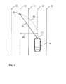
- FIG. 2 is a view illustrating a target distance and a circular trace in a current driving lane
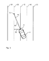
- FIG. 3 is a view illustrating a target distance and a circular trace, which are changed in real time, during a change of a lane.
- the target lane generator 110 when an intention of a driver for changing a lane to a left side of Fig. 2 is sensed or a lane change is determined according to a route planner from current driving lanes 10 and 20, the target lane generator 110 generates a virtual target lane 30 by shifting to a left side by a width of the current driving lanes 10 and 20.
- Information on the current driving lanes 10 and 20 may be detected by a camera system and a lane detection module installed in a vehicle 4.
- the current vehicle 4 of Fig. 2 is in a state of keeping a front driving based on a center lane 40 of the current driving lanes 10 and 20.
- the target distance generator 120 generates a target distance 70 that is a distance from the vehicle 4 to a predetermined target keeping point 72.
- the target distance generator 120 needs to generate a target distance longer than that of a lane keeping assist system (hereinafter, referred to as an "LKAS"). This is because a larger traverse directional departure distance 60 between the center lane 50 of the target lane and the vehicle 4 is generated when changing a lane as compared to a case where the lane is kept, so that a radius of a circular trace is decreased and thus a pulling phenomenon becomes severe according to an increase in a target rate.
- LKAS lane keeping assist system
- the target distance generator 120 calculates the target distance 70 by multiplying the target distance used in the LKAS by a degree of influence (gain * traverse directional departure distance + 1).
- the target distance used in the LKAS may be calculated by reflecting a speed of the vehicle and a curvature of a road.
- the speed of the vehicle may be obtained from a sensor 2, and the curvature of the road may be detected by the camera system and the lane detection module installed in the vehicle 4.
- the target distance 70 Since the target distance 70 has the traverse directional departure distance 60 as a variable, the target distance 70 is also changed in response to the traverse directional departure distance 60 that is changed in real time during the change of the lane by the corresponding vehicle 4.
- the traverse directional departure distance 60 when the vehicle 4 is changing the lane, the traverse directional departure distance 60 is smaller than the traverse directional departure distance 60 illustrated in Fig. 2 . Accordingly, the target distance 70 is large at an initial stage of the lane change, but the target distance 70 is decreased as the lane change progresses.
- the traverse directional departure distance 60 becomes 0, so that the existing target distance used in the LKAS is used. Since the target distance 70 is changed in real time according to a process of the lane change as described above, it is possible to minimize a sense of steering difference and a pulling phenomenon of a vehicle.
- the circular trace generator 130 generates a circular trace passing a current point of the vehicle 4 and a point on the center line of the target lane spaced by the target distance based on the vehicle 4 and having a driving direction of the vehicle as a tangential direction in real time.
- a circular trace 80 passing a center 71 of a front end of the vehicle 4 and a point 72 on the target lane may be generated.
- the steering controller 140 calculates a target rate and a target steering angle so as to keep the circular trace 80 that is generated in real time.
- the steering controller 140 may first calculate the target rate based on the traverse directional departure distance 60, a departure angle between the center line 50 of the target lane and the vehicle 4, an amount of side slip of the vehicle 4, and a speed of the vehicle.
- the steering controller 140 calculates the target steering angle based on the calculated target rate.
- the steering controller 140 induces the corresponding vehicle 4 to be steered at the target steering angle by transmitting the calculated target steering angle to a motor driven power steering (MDPS) 3.
- MDPS motor driven power steering
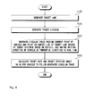
- Fig. 4 is a flowchart illustrating a control method of a vehicle for changing a lane according to an exemplary embodiment of the present invention.
- the target lane generator 110 first generates a target lane in a predetermined direction when an intention of a driver for changing a lane is sensed or it is necessary to change a lane according to a route planner (S100).
- the target distance generator 120 generates the target distance 70 that is a distance from the vehicle 4 to the predetermined target keeping point 72 (S200).
- the circular trace generator 130 generates a circular trace passing a current point of the vehicle 4 and a point on the center line of the target lane spaced by the target distance based on the vehicle 4, and having a driving direction of the vehicle as a tangential direction in real time (S300).
- the steering controller 140 calculates a target rate and a target steering angle so as to keep the circular trace 80 that is generated in real time (S400).
Landscapes
- Engineering & Computer Science (AREA)
- Transportation (AREA)
- Mechanical Engineering (AREA)
- Chemical & Material Sciences (AREA)
- Combustion & Propulsion (AREA)
- Physics & Mathematics (AREA)
- General Physics & Mathematics (AREA)
- Automation & Control Theory (AREA)
- Mathematical Physics (AREA)
- Steering Control In Accordance With Driving Conditions (AREA)
- Traffic Control Systems (AREA)
Abstract
Description
- This application claims priority to and the benefit of Korean Patent Application No.
10-2012-0125041 - The present invention relates to a control apparatus of a vehicle for changing a lane, and a control method of the same, and more particularly, to a control apparatus of a vehicle for changing a lane, which controls so that a vehicle automatically changes a lane based on road information obtained from a camera and driving information obtained from various sensors, and a control method of the same.
- In a control system of an intelligent vehicle, a lane keeping assist system (hereinafter, referred to as an "LKAS") is an essential system used for safety of a driver. The KLAS is generally configured so as to perform lane keeping control so as to prevent a vehicle from departing from a detected lane or warn lane departure by detecting the lane and sensing a driving state of the vehicle.
- The road information including a lane may be detected by obtaining a front road image through a camera sensor mounted between a windshield and a room mirror of a vehicle and image-processing the obtained road image in an LKAS camera system. The driving information may be sensed through information obtained from various sensors and an electronic control unit (ECU) mounted in the vehicle.
- In the meantime, a system for giving a driver a warning according to existence or nonexistence of a rear vehicle and a driving state when an intention of a driver for changing a lane is sensed in the LKAS has been suggested. In addition to the aforementioned system, a lane changing system for automatically changing a lane to a target lane by utilizing road information of a camera system has been suggested. In general, the lane changing system performs control for changing a lane by utilizing a spaced distance between a virtual lane for inducing a vehicle to a target lane and the vehicle. However, since the lane changing system performs the control by reflecting only the spaced distance between the virtual lane and the vehicle, there is a problem in that steering is unsafe due to a sense of steering difference and a pulling phenomenon of a vehicle.
- The present invention has been made in an effort to provide a control apparatus of a vehicle for changing a lane, which is capable of preventing a sense of steering difference and a pulling phenomenon of a vehicle, and a control method of the same.
- An exemplary embodiment of the present invention provides a control apparatus of a vehicle for changing a lane, including: a target lane generator configured to generate a target lane; a target distance generator configured to generate a target distance; a circular trace generator configured to generate a circular trace passing a current point of a vehicle and a point on a center line of the target lane spaced by the target distance based on the vehicle, and having a driving direction of the vehicle as a tangential direction in real time; and a steering controller configured to calculate a target rate and a target steering angle so as for the vehicle to follow the generated circular trace.
- The target lane generator may generate a virtual target lane by shifting to a predetermined direction by a width of a current driving lane.
- The target distance generator may calculate the target distance based on a speed of the vehicle, and a traverse directional departure distance of the vehicle from the center line of the target lane.
- The steering controller may calculate the target rate based on a departure distance of the vehicle from the center line of the target lane, a departure angle between the center line of the target lane and the vehicle, an amount of side slip of the vehicle, and a speed of the vehicle.
- The steering controller may calculate the target steering angle based on the target rate.
- Another exemplary embodiment of the present invention provides a control method of a vehicle for changing a lane, including: a) generating a target lane; b) generating a target distance; c) generating a circular trace passing a current point of a vehicle and a point on a center line of the target lane spaced by the target distance based on the vehicle, and having a driving direction of the vehicle as a tangential direction in real time; and d) calculating a target rate and a target steering angle so as for the vehicle to follow the generated circular trace.
- In step a), a virtual target lane may be generated by shifting to a predetermined direction by a width of a current driving lane.
- In step b), the target distance may be calculated based on a speed of the vehicle, and a traverse directional departure distance of the vehicle from the center line of the target lane.
- In step d), the target rate may be calculated based on a departure distance of the vehicle from the center line of the target lane, a departure angle between the center line of the target lane and the vehicle, an amount of side slip of the vehicle, and a speed of the vehicle.
- In step d), the target steering angle may be calculated based on the target rate.
- Accordingly, to the control apparatus of the vehicle for changing the lane and the control method of the same according to the present invention, it is possible to prevent a sense of steering difference and a pulling phenomenon of the vehicle when changing a lane by controlling to change the lane based on the target distance that is changed in real time in response to a speed of the vehicle and the traverse directional departure distance from the center line of the target lane.
- The foregoing summary is illustrative only and is not intended to be in any way limiting. In addition to the illustrative aspects, embodiments, and features described above, further aspects, embodiments, and features will become apparent by reference to the drawings and the following detailed description.
-
- Fig. 1
- is a block diagram illustrating a control apparatus of a vehicle for changing a lane according to an exemplary embodiment of the present invention.
- Fig. 2
- is a view illustrating a target distance and a circular trace in a current driving lane.
- Fig. 3
- is a view illustrating a target distance and a circular trace, which are changed in real time, during a change of a lane.
- Fig. 4
- is a flowchart illustrating a control method of a vehicle for changing a lane according to an exemplary embodiment of the present invention.
- It should be understood that the appended drawings are not necessarily to scale, presenting a somewhat simplified representation of various features illustrative of the basic principles of the invention. The specific design features of the present invention as disclosed herein, including, for example, specific dimensions, orientations, locations, and shapes will be determined in part by the particular intended application and use environment.
- In the Figures, reference numbers refer to the same or equivalent parts of the present invention throughout the several figures of the drawing.
- Hereinafter, an exemplary embodiment of the present invention will be described in detail with reference to the accompanying drawings. First of all, we should note that in giving reference numerals to elements of each drawing, like reference numerals refer to like elements even though like elements are shown in different drawings. It should be understood that although the exemplary embodiment of the present invention are described hereafter, the spirit of the present invention is not limited thereto and may be changed and modified in various ways by those skilled in the art.
- The present invention is based on a lane changing control apparatus for automatically changing a lane, and has a technical characteristic of controlling steering of a vehicle in real time based on a target distance and a circular trace, which are changed in real time, during a change of a lane.
-
Fig. 1 is a block diagram illustrating a control apparatus of a vehicle for changing a lane according to an exemplary embodiment of the present invention. Referring toFig. 1 , acontrol apparatus 100 of the vehicle for changing the lane according to the exemplary embodiment of the present invention includes atarget lane generator 110, atarget distance generator 120, acircular trace generator 130, and asteering controller 140. - First, the
target lane generator 110 generates a target lane in a predetermined direction when a lane changing intention of a driver is sensed or it is necessary to change a lane according to a route planner. In the exemplary embodiment, thetarget lane generator 110 may generate a virtual target lane by shifting in a predetermined direction by a width of a current driving lane. -
Fig. 2 is a view illustrating a target distance and a circular trace in a current driving lane, andFIG. 3 is a view illustrating a target distance and a circular trace, which are changed in real time, during a change of a lane. - Referring to
Fig. 2 , when an intention of a driver for changing a lane to a left side ofFig. 2 is sensed or a lane change is determined according to a route planner fromcurrent driving lanes target lane generator 110 generates avirtual target lane 30 by shifting to a left side by a width of thecurrent driving lanes current driving lanes vehicle 4. - The
current vehicle 4 ofFig. 2 is in a state of keeping a front driving based on acenter lane 40 of thecurrent driving lanes - The
target distance generator 120 generates atarget distance 70 that is a distance from thevehicle 4 to a predeterminedtarget keeping point 72. In order to change the lane, thetarget distance generator 120 needs to generate a target distance longer than that of a lane keeping assist system (hereinafter, referred to as an "LKAS"). This is because a larger traversedirectional departure distance 60 between thecenter lane 50 of the target lane and thevehicle 4 is generated when changing a lane as compared to a case where the lane is kept, so that a radius of a circular trace is decreased and thus a pulling phenomenon becomes severe according to an increase in a target rate. Accordingly, thetarget distance generator 120 calculates thetarget distance 70 by multiplying the target distance used in the LKAS by a degree of influence (gain * traverse directional departure distance + 1). Here, the target distance used in the LKAS may be calculated by reflecting a speed of the vehicle and a curvature of a road. The speed of the vehicle may be obtained from asensor 2, and the curvature of the road may be detected by the camera system and the lane detection module installed in thevehicle 4. - Since the
target distance 70 has the traversedirectional departure distance 60 as a variable, thetarget distance 70 is also changed in response to the traversedirectional departure distance 60 that is changed in real time during the change of the lane by thecorresponding vehicle 4. Referring toFig. 3 , it can be seen that when thevehicle 4 is changing the lane, the traversedirectional departure distance 60 is smaller than the traversedirectional departure distance 60 illustrated inFig. 2 . Accordingly, thetarget distance 70 is large at an initial stage of the lane change, but thetarget distance 70 is decreased as the lane change progresses. When the lane change is completed, the traversedirectional departure distance 60 becomes 0, so that the existing target distance used in the LKAS is used. Since thetarget distance 70 is changed in real time according to a process of the lane change as described above, it is possible to minimize a sense of steering difference and a pulling phenomenon of a vehicle. - The
circular trace generator 130 generates a circular trace passing a current point of thevehicle 4 and a point on the center line of the target lane spaced by the target distance based on thevehicle 4 and having a driving direction of the vehicle as a tangential direction in real time. In the exemplary embodiment, acircular trace 80 passing acenter 71 of a front end of thevehicle 4 and apoint 72 on the target lane may be generated. When changing a lane, it is possible to minimize a sense of steering difference and a pulling phenomenon by controlling thevehicle 4 so as to keep thecircular trace 80 generated in real time as described above. - The
steering controller 140 calculates a target rate and a target steering angle so as to keep thecircular trace 80 that is generated in real time. Thesteering controller 140 may first calculate the target rate based on the traversedirectional departure distance 60, a departure angle between thecenter line 50 of the target lane and thevehicle 4, an amount of side slip of thevehicle 4, and a speed of the vehicle. Thesteering controller 140 calculates the target steering angle based on the calculated target rate. Thesteering controller 140 induces thecorresponding vehicle 4 to be steered at the target steering angle by transmitting the calculated target steering angle to a motor driven power steering (MDPS) 3. -
Fig. 4 is a flowchart illustrating a control method of a vehicle for changing a lane according to an exemplary embodiment of the present invention. - Referring to
Fig. 4 , in the control method of the vehicle for changing the lane according to the exemplary embodiment of the present invention, thetarget lane generator 110 first generates a target lane in a predetermined direction when an intention of a driver for changing a lane is sensed or it is necessary to change a lane according to a route planner (S100). Next, thetarget distance generator 120 generates thetarget distance 70 that is a distance from thevehicle 4 to the predetermined target keeping point 72 (S200). Subsequently, thecircular trace generator 130 generates a circular trace passing a current point of thevehicle 4 and a point on the center line of the target lane spaced by the target distance based on thevehicle 4, and having a driving direction of the vehicle as a tangential direction in real time (S300). Next, thesteering controller 140 calculates a target rate and a target steering angle so as to keep thecircular trace 80 that is generated in real time (S400). - As described above, the exemplary embodiments have been described and illustrated in the drawings and the specification. The exemplary embodiments were chosen and described in order to explain certain principles of the invention and their practical application, to thereby enable others skilled in the art to make and utilize various exemplary embodiments of the present invention, as well as various alternatives and modifications thereof. As is evident from the foregoing description, certain aspects of the present invention are not limited by the particular details of the examples illustrated herein, and it is therefore contemplated that other modifications and applications, or equivalents thereof, will occur to those skilled in the art. Many changes, modifications, variations and other uses and applications of the present construction will, however, become apparent to those skilled in the art after considering the specification and the accompanying drawings. All such changes, modifications, variations and other uses and applications which do not depart from the spirit and scope of the invention are deemed to be covered by the invention which is limited only by the claims which follow.
Claims (10)
- A control apparatus of a vehicle for changing a lane, comprising:a target lane generator configured to generate a target lane;a target distance generator configured to generate a target distance;a circular trace generator configured to generate a circular trace passing a current point of a vehicle and a point on a center line of the target lane spaced by the target distance based on the vehicle, and having a driving direction of the vehicle as a tangential direction in real time; anda steering controller configured to calculate a target rate and a target steering angle so as for the vehicle to follow the generated circular trace.
- The control apparatus of claim 1, wherein the target lane generator generates a virtual target lane by shifting to a predetermined direction by a width of a current driving lane.
- The control apparatus of claim 1, wherein the target distance generator calculates the target distance based on a speed of the vehicle, and a traverse directional departure distance of the vehicle from the center line of the target lane.
- The control apparatus of claim 1, wherein the steering controller calculates the target rate based on a departure distance of the vehicle from the center line of the target lane, a departure angle between the center line of the target lane and the vehicle, an amount of side slip of the vehicle, and a speed of the vehicle.
- The control apparatus of claim 4, wherein the steering controller calculates the target steering angle based on the target rate.
- A control method of a vehicle for changing a lane, comprising:a) generating a target lane;b) generating a target distance;c) generating a circular trace passing a current point of a vehicle and a point on a center line of the target lane spaced by the target distance based on the vehicle, and having a driving direction of the vehicle as a tangential direction up to the center line of the target lane in real time; andd) calculating a target rate and a target steering angle so as for the vehicle to follow the generated circular trace.
- The control method of claim 6, wherein in step a), a virtual target lane is generated by shifting to a predetermined direction by a width of a current driving lane.
- The control method of claim 7, wherein in step b), the target distance is calculated based on a speed of the vehicle, and a traverse directional departure distance of the vehicle from the center line of the target lane.
- The control method of claim 8, wherein in step d), the target rate is calculated based on a departure distance of the vehicle from the center line of the target lane, a departure angle between the center line of the target lane and the vehicle, an amount of side slip of the vehicle, and a speed of the vehicle.
- The control method of claim 9, wherein in step d), the target steering angle is calculated based on the target rate.
Applications Claiming Priority (1)
| Application Number | Priority Date | Filing Date | Title |
|---|---|---|---|
| KR1020120125041A KR101398223B1 (en) | 2012-11-06 | 2012-11-06 | Control apparatus of vehicle for changing lane and Control method of the same |
Publications (2)
| Publication Number | Publication Date |
|---|---|
| EP2727794A1 true EP2727794A1 (en) | 2014-05-07 |
| EP2727794B1 EP2727794B1 (en) | 2021-03-10 |
Family
ID=47713848
Family Applications (1)
| Application Number | Title | Priority Date | Filing Date |
|---|---|---|---|
| EP13152250.0A Active EP2727794B1 (en) | 2012-11-06 | 2013-01-22 | Control apparatus of vehicle for changing lane and control method of the same |
Country Status (5)
| Country | Link |
|---|---|
| US (1) | US9108664B2 (en) |
| EP (1) | EP2727794B1 (en) |
| JP (1) | JP5514333B2 (en) |
| KR (1) | KR101398223B1 (en) |
| CN (1) | CN103809593B (en) |
Cited By (2)
| Publication number | Priority date | Publication date | Assignee | Title |
|---|---|---|---|---|
| CN111681452A (en) * | 2020-01-19 | 2020-09-18 | 重庆大学 | A dynamic lane-changing trajectory planning method for driverless vehicles based on Frenet coordinate system |
| US20220024515A1 (en) * | 2017-04-14 | 2022-01-27 | Nissan Motor Co., Ltd. | Vehicle Control Method and Vehicle Control Device |
Families Citing this family (18)
| Publication number | Priority date | Publication date | Assignee | Title |
|---|---|---|---|---|
| CN103403778B (en) * | 2011-02-28 | 2016-01-20 | 丰田自动车株式会社 | Driving support device and method |
| US9707996B2 (en) * | 2011-08-31 | 2017-07-18 | Toyota Jidosha Kabushiki Kaisha | Vehicle drive-control device |
| JP6348285B2 (en) * | 2014-01-08 | 2018-06-27 | 日野自動車株式会社 | Steering control device |
| JP6377942B2 (en) * | 2014-04-14 | 2018-08-22 | 日野自動車株式会社 | Driving assistance device |
| KR101551096B1 (en) * | 2014-06-05 | 2015-09-21 | 현대자동차주식회사 | Lane changing apparatus and method of autonomous vehicle |
| US20160307441A1 (en) * | 2015-04-14 | 2016-10-20 | Delphi Technologies, Inc. | System for lane selection by an automated vehicle |
| CN107848534B (en) * | 2015-08-06 | 2021-04-02 | 本田技研工业株式会社 | Vehicle control device, vehicle control method, and medium for storing vehicle control program |
| KR102319082B1 (en) * | 2015-09-14 | 2021-10-29 | 주식회사 만도모빌리티솔루션즈 | Method for controlling a vehicle tracking and Apparatus thereof |
| US20180259961A1 (en) * | 2017-03-07 | 2018-09-13 | Delphi Technologies, Inc. | Lane-changing system for automated vehicles |
| US10267911B2 (en) | 2017-03-31 | 2019-04-23 | Ford Global Technologies, Llc | Steering wheel actuation |
| CN107323450B (en) * | 2017-06-08 | 2019-08-13 | 广州汽车集团股份有限公司 | The control method and device of vehicle lane change, storage medium |
| CN109109862A (en) * | 2017-06-23 | 2019-01-01 | 上海汽车集团股份有限公司 | A kind of control method and device of the automatic lane-change of vehicle |
| CN110018632B (en) * | 2018-06-22 | 2020-10-09 | 长城汽车股份有限公司 | Vehicle lane change control method and device |
| CN110400490B (en) * | 2019-08-08 | 2022-02-25 | 腾讯科技(深圳)有限公司 | Trajectory prediction method and apparatus |
| FR3117972B1 (en) * | 2020-12-17 | 2022-11-04 | Renault Sas | Control method for controlling the movement of an autonomous motor vehicle |
| CN113978467B (en) * | 2021-10-28 | 2023-06-20 | 江铃汽车股份有限公司 | A control method for vehicle automatic lane change based on sine function |
| CN114397120B (en) * | 2022-01-14 | 2022-12-02 | 襄阳达安汽车检测中心有限公司 | A high-precision vehicle steering tracking test method and system |
| US12252127B2 (en) * | 2022-04-19 | 2025-03-18 | Aptiv Technologies AG | Dynamically calculating lane change trajectories |
Citations (2)
| Publication number | Priority date | Publication date | Assignee | Title |
|---|---|---|---|---|
| DE102006000638A1 (en) * | 2006-01-03 | 2007-07-05 | Robert Bosch Gmbh | Vehicle driver assistance method, involves determining time required for vehicle to reach up to marking based on process of marking of edge of lane and process of intended track of vehicle |
| DE102008060770A1 (en) * | 2008-12-05 | 2009-09-17 | Daimler Ag | Driver aiding method for use during parking of car, involves producing representation of trajectory via stored reference circle data in dependent of steering angle, vehicle data, and position and adjustment of camera |
Family Cites Families (19)
| Publication number | Priority date | Publication date | Assignee | Title |
|---|---|---|---|---|
| JP3599144B2 (en) * | 1996-05-09 | 2004-12-08 | 本田技研工業株式会社 | Vehicle steering assist system |
| JPH10105232A (en) * | 1996-09-30 | 1998-04-24 | Mitsubishi Motors Corp | Lane changing device for autonomous driving road system |
| JP2003063273A (en) * | 2001-08-30 | 2003-03-05 | Hitachi Ltd | Vehicle travel control device |
| JP2006264623A (en) | 2005-03-25 | 2006-10-05 | Mitsubishi Fuso Truck & Bus Corp | Lane maintenance support device |
| JP2008149855A (en) * | 2006-12-15 | 2008-07-03 | Toyota Motor Corp | Vehicle target course change trajectory generation device |
| JP2009040267A (en) * | 2007-08-09 | 2009-02-26 | Toyota Motor Corp | Travel control device |
| JP2009061878A (en) * | 2007-09-05 | 2009-03-26 | Toyota Motor Corp | Travel control device |
| US8392064B2 (en) | 2008-05-27 | 2013-03-05 | The Board Of Trustees Of The Leland Stanford Junior University | Systems, methods and devices for adaptive steering control of automotive vehicles |
| US8170739B2 (en) * | 2008-06-20 | 2012-05-01 | GM Global Technology Operations LLC | Path generation algorithm for automated lane centering and lane changing control system |
| KR101356203B1 (en) | 2008-07-07 | 2014-01-24 | 현대자동차주식회사 | Aytomomous travelling controll system |
| KR20100027565A (en) | 2008-09-03 | 2010-03-11 | 오세훈 | The camera wireless sync system which is radio id recognition function |
| JP5146243B2 (en) | 2008-10-10 | 2013-02-20 | トヨタ自動車株式会社 | Lane departure control device |
| JP5886185B2 (en) * | 2009-03-04 | 2016-03-16 | コンティネンタル・テーベス・アクチエンゲゼルシヤフト・ウント・コンパニー・オッフェネ・ハンデルスゲゼルシヤフト | Method for automatically recognizing driving maneuvers of a motor vehicle and driver assistance system including this method |
| JP5278378B2 (en) * | 2009-07-30 | 2013-09-04 | 日産自動車株式会社 | Vehicle driving support device and vehicle driving support method |
| JP5421019B2 (en) * | 2009-08-03 | 2014-02-19 | トヨタ自動車株式会社 | Vehicle travel support device |
| KR101272424B1 (en) | 2009-09-24 | 2013-06-07 | 주식회사 만도 | Method and System for Assisting Lane Keeping |
| KR101399670B1 (en) | 2010-03-17 | 2014-05-27 | 주식회사 만도 | Lane keeping control method and lane keeping control system |
| JP5429062B2 (en) * | 2010-06-11 | 2014-02-26 | トヨタ自動車株式会社 | Vehicle travel control device |
| RU2566175C1 (en) * | 2011-08-31 | 2015-10-20 | Ниссан Мотор Ко., Лтд. | Vehicle driver aid |
-
2012
- 2012-11-06 KR KR1020120125041A patent/KR101398223B1/en active Active
-
2013
- 2013-01-06 CN CN201310003363.6A patent/CN103809593B/en active Active
- 2013-01-18 JP JP2013007249A patent/JP5514333B2/en active Active
- 2013-01-22 EP EP13152250.0A patent/EP2727794B1/en active Active
- 2013-03-11 US US13/793,257 patent/US9108664B2/en active Active
Patent Citations (2)
| Publication number | Priority date | Publication date | Assignee | Title |
|---|---|---|---|---|
| DE102006000638A1 (en) * | 2006-01-03 | 2007-07-05 | Robert Bosch Gmbh | Vehicle driver assistance method, involves determining time required for vehicle to reach up to marking based on process of marking of edge of lane and process of intended track of vehicle |
| DE102008060770A1 (en) * | 2008-12-05 | 2009-09-17 | Daimler Ag | Driver aiding method for use during parking of car, involves producing representation of trajectory via stored reference circle data in dependent of steering angle, vehicle data, and position and adjustment of camera |
Cited By (3)
| Publication number | Priority date | Publication date | Assignee | Title |
|---|---|---|---|---|
| US20220024515A1 (en) * | 2017-04-14 | 2022-01-27 | Nissan Motor Co., Ltd. | Vehicle Control Method and Vehicle Control Device |
| US11498617B2 (en) * | 2017-04-14 | 2022-11-15 | Nissan Motor Co., Ltd. | Vehicle control method and vehicle control device |
| CN111681452A (en) * | 2020-01-19 | 2020-09-18 | 重庆大学 | A dynamic lane-changing trajectory planning method for driverless vehicles based on Frenet coordinate system |
Also Published As
| Publication number | Publication date |
|---|---|
| KR20140058254A (en) | 2014-05-14 |
| CN103809593A (en) | 2014-05-21 |
| KR101398223B1 (en) | 2014-05-23 |
| US20140129084A1 (en) | 2014-05-08 |
| JP2014091512A (en) | 2014-05-19 |
| CN103809593B (en) | 2018-02-16 |
| JP5514333B2 (en) | 2014-06-04 |
| US9108664B2 (en) | 2015-08-18 |
| EP2727794B1 (en) | 2021-03-10 |
Similar Documents
| Publication | Publication Date | Title |
|---|---|---|
| US9108664B2 (en) | Control apparatus of vehicle for changing lane and control method of the same | |
| US9037373B2 (en) | Lateral control apparatus of vehicle and control method of the same | |
| JP6432679B2 (en) | Stop position setting apparatus and method | |
| CN107128314B (en) | The vehicle lateral control of enhancing for towing vehicle | |
| US9045144B2 (en) | Third-order polynomial-based course prediction for driver assistance functions | |
| US10081358B2 (en) | Lane departure prevention apparatus | |
| JP5141849B2 (en) | Vehicle travel support device | |
| EP2741270B1 (en) | Driving assistance apparatus and driving assistance method | |
| US9014917B2 (en) | Method and device for adjusting an intervention torque of a steering assistance system | |
| EP3150465B1 (en) | Method and system for indicating a potential lane shift of a vehicle | |
| CN104627161B (en) | The adaptive learning algorithms device and its control method of vehicle with sensing distance regulatory function | |
| EP2803547A2 (en) | Collision mitigation apparatus | |
| CN107148378B (en) | Method for operating a driver assistance system and driver assistance system | |
| JP2015138330A (en) | vehicle speed control device | |
| KR20180069505A (en) | Apparatus for path planning of vehicle and method thereof | |
| US11987251B2 (en) | Adaptive rationalizer for vehicle perception systems toward robust automated driving control | |
| JP5453765B2 (en) | Road shape estimation device | |
| KR102270287B1 (en) | System and Method for Lane Keep Asistance | |
| JP2013052754A (en) | Parking support device | |
| KR20120135697A (en) | Lane departure warning and lane keeping assistance system for vehicle and control method thereof | |
| CN108725316B (en) | Driving lane guidance system and control method thereof | |
| US12546625B2 (en) | System and method for providing driver assistance | |
| JP2008059366A (en) | Steering angle determination device, automobile and steering angle determination method | |
| JP6330868B2 (en) | Vehicle control device | |
| KR20140064388A (en) | Control method for lane keeping assist of vehicle and apparatus for lane keeping assist implementing the same |
Legal Events
| Date | Code | Title | Description |
|---|---|---|---|
| PUAI | Public reference made under article 153(3) epc to a published international application that has entered the european phase |
Free format text: ORIGINAL CODE: 0009012 |
|
| 17P | Request for examination filed |
Effective date: 20130122 |
|
| AK | Designated contracting states |
Kind code of ref document: A1 Designated state(s): AL AT BE BG CH CY CZ DE DK EE ES FI FR GB GR HR HU IE IS IT LI LT LU LV MC MK MT NL NO PL PT RO RS SE SI SK SM TR |
|
| AX | Request for extension of the european patent |
Extension state: BA ME |
|
| RBV | Designated contracting states (corrected) |
Designated state(s): AL AT BE BG CH CY CZ DE DK EE ES FI FR GB GR HR HU IE IS IT LI LT LU LV MC MK MT NL NO PL PT RO RS SE SI SK SM TR |
|
| 17Q | First examination report despatched |
Effective date: 20160628 |
|
| STAA | Information on the status of an ep patent application or granted ep patent |
Free format text: STATUS: EXAMINATION IS IN PROGRESS |
|
| RIC1 | Information provided on ipc code assigned before grant |
Ipc: B62D 15/02 20060101ALI20200519BHEP Ipc: G08G 1/16 20060101ALI20200519BHEP Ipc: B62D 1/00 20060101AFI20200519BHEP |
|
| GRAP | Despatch of communication of intention to grant a patent |
Free format text: ORIGINAL CODE: EPIDOSNIGR1 |
|
| STAA | Information on the status of an ep patent application or granted ep patent |
Free format text: STATUS: GRANT OF PATENT IS INTENDED |
|
| INTG | Intention to grant announced |
Effective date: 20200828 |
|
| GRAS | Grant fee paid |
Free format text: ORIGINAL CODE: EPIDOSNIGR3 |
|
| GRAA | (expected) grant |
Free format text: ORIGINAL CODE: 0009210 |
|
| STAA | Information on the status of an ep patent application or granted ep patent |
Free format text: STATUS: THE PATENT HAS BEEN GRANTED |
|
| AK | Designated contracting states |
Kind code of ref document: B1 Designated state(s): AL AT BE BG CH CY CZ DE DK EE ES FI FR GB GR HR HU IE IS IT LI LT LU LV MC MK MT NL NO PL PT RO RS SE SI SK SM TR |
|
| REG | Reference to a national code |
Ref country code: GB Ref legal event code: FG4D |
|
| REG | Reference to a national code |
Ref country code: AT Ref legal event code: REF Ref document number: 1369532 Country of ref document: AT Kind code of ref document: T Effective date: 20210315 Ref country code: CH Ref legal event code: EP |
|
| REG | Reference to a national code |
Ref country code: IE Ref legal event code: FG4D |
|
| REG | Reference to a national code |
Ref country code: DE Ref legal event code: R096 Ref document number: 602013076130 Country of ref document: DE |
|
| REG | Reference to a national code |
Ref country code: LT Ref legal event code: MG9D |
|
| PG25 | Lapsed in a contracting state [announced via postgrant information from national office to epo] |
Ref country code: GR Free format text: LAPSE BECAUSE OF FAILURE TO SUBMIT A TRANSLATION OF THE DESCRIPTION OR TO PAY THE FEE WITHIN THE PRESCRIBED TIME-LIMIT Effective date: 20210611 Ref country code: HR Free format text: LAPSE BECAUSE OF FAILURE TO SUBMIT A TRANSLATION OF THE DESCRIPTION OR TO PAY THE FEE WITHIN THE PRESCRIBED TIME-LIMIT Effective date: 20210310 Ref country code: FI Free format text: LAPSE BECAUSE OF FAILURE TO SUBMIT A TRANSLATION OF THE DESCRIPTION OR TO PAY THE FEE WITHIN THE PRESCRIBED TIME-LIMIT Effective date: 20210310 Ref country code: LT Free format text: LAPSE BECAUSE OF FAILURE TO SUBMIT A TRANSLATION OF THE DESCRIPTION OR TO PAY THE FEE WITHIN THE PRESCRIBED TIME-LIMIT Effective date: 20210310 Ref country code: NO Free format text: LAPSE BECAUSE OF FAILURE TO SUBMIT A TRANSLATION OF THE DESCRIPTION OR TO PAY THE FEE WITHIN THE PRESCRIBED TIME-LIMIT Effective date: 20210610 Ref country code: BG Free format text: LAPSE BECAUSE OF FAILURE TO SUBMIT A TRANSLATION OF THE DESCRIPTION OR TO PAY THE FEE WITHIN THE PRESCRIBED TIME-LIMIT Effective date: 20210610 |
|
| REG | Reference to a national code |
Ref country code: AT Ref legal event code: MK05 Ref document number: 1369532 Country of ref document: AT Kind code of ref document: T Effective date: 20210310 |
|
| REG | Reference to a national code |
Ref country code: NL Ref legal event code: MP Effective date: 20210310 |
|
| PG25 | Lapsed in a contracting state [announced via postgrant information from national office to epo] |
Ref country code: SE Free format text: LAPSE BECAUSE OF FAILURE TO SUBMIT A TRANSLATION OF THE DESCRIPTION OR TO PAY THE FEE WITHIN THE PRESCRIBED TIME-LIMIT Effective date: 20210310 Ref country code: RS Free format text: LAPSE BECAUSE OF FAILURE TO SUBMIT A TRANSLATION OF THE DESCRIPTION OR TO PAY THE FEE WITHIN THE PRESCRIBED TIME-LIMIT Effective date: 20210310 Ref country code: LV Free format text: LAPSE BECAUSE OF FAILURE TO SUBMIT A TRANSLATION OF THE DESCRIPTION OR TO PAY THE FEE WITHIN THE PRESCRIBED TIME-LIMIT Effective date: 20210310 |
|
| PG25 | Lapsed in a contracting state [announced via postgrant information from national office to epo] |
Ref country code: NL Free format text: LAPSE BECAUSE OF FAILURE TO SUBMIT A TRANSLATION OF THE DESCRIPTION OR TO PAY THE FEE WITHIN THE PRESCRIBED TIME-LIMIT Effective date: 20210310 |
|
| PG25 | Lapsed in a contracting state [announced via postgrant information from national office to epo] |
Ref country code: CZ Free format text: LAPSE BECAUSE OF FAILURE TO SUBMIT A TRANSLATION OF THE DESCRIPTION OR TO PAY THE FEE WITHIN THE PRESCRIBED TIME-LIMIT Effective date: 20210310 Ref country code: EE Free format text: LAPSE BECAUSE OF FAILURE TO SUBMIT A TRANSLATION OF THE DESCRIPTION OR TO PAY THE FEE WITHIN THE PRESCRIBED TIME-LIMIT Effective date: 20210310 Ref country code: SM Free format text: LAPSE BECAUSE OF FAILURE TO SUBMIT A TRANSLATION OF THE DESCRIPTION OR TO PAY THE FEE WITHIN THE PRESCRIBED TIME-LIMIT Effective date: 20210310 Ref country code: AT Free format text: LAPSE BECAUSE OF FAILURE TO SUBMIT A TRANSLATION OF THE DESCRIPTION OR TO PAY THE FEE WITHIN THE PRESCRIBED TIME-LIMIT Effective date: 20210310 |
|
| PG25 | Lapsed in a contracting state [announced via postgrant information from national office to epo] |
Ref country code: ES Free format text: LAPSE BECAUSE OF FAILURE TO SUBMIT A TRANSLATION OF THE DESCRIPTION OR TO PAY THE FEE WITHIN THE PRESCRIBED TIME-LIMIT Effective date: 20210310 Ref country code: PL Free format text: LAPSE BECAUSE OF FAILURE TO SUBMIT A TRANSLATION OF THE DESCRIPTION OR TO PAY THE FEE WITHIN THE PRESCRIBED TIME-LIMIT Effective date: 20210310 Ref country code: PT Free format text: LAPSE BECAUSE OF FAILURE TO SUBMIT A TRANSLATION OF THE DESCRIPTION OR TO PAY THE FEE WITHIN THE PRESCRIBED TIME-LIMIT Effective date: 20210712 Ref country code: SK Free format text: LAPSE BECAUSE OF FAILURE TO SUBMIT A TRANSLATION OF THE DESCRIPTION OR TO PAY THE FEE WITHIN THE PRESCRIBED TIME-LIMIT Effective date: 20210310 Ref country code: RO Free format text: LAPSE BECAUSE OF FAILURE TO SUBMIT A TRANSLATION OF THE DESCRIPTION OR TO PAY THE FEE WITHIN THE PRESCRIBED TIME-LIMIT Effective date: 20210310 Ref country code: IS Free format text: LAPSE BECAUSE OF FAILURE TO SUBMIT A TRANSLATION OF THE DESCRIPTION OR TO PAY THE FEE WITHIN THE PRESCRIBED TIME-LIMIT Effective date: 20210710 |
|
| REG | Reference to a national code |
Ref country code: DE Ref legal event code: R097 Ref document number: 602013076130 Country of ref document: DE |
|
| PLBE | No opposition filed within time limit |
Free format text: ORIGINAL CODE: 0009261 |
|
| STAA | Information on the status of an ep patent application or granted ep patent |
Free format text: STATUS: NO OPPOSITION FILED WITHIN TIME LIMIT |
|
| PG25 | Lapsed in a contracting state [announced via postgrant information from national office to epo] |
Ref country code: AL Free format text: LAPSE BECAUSE OF FAILURE TO SUBMIT A TRANSLATION OF THE DESCRIPTION OR TO PAY THE FEE WITHIN THE PRESCRIBED TIME-LIMIT Effective date: 20210310 Ref country code: DK Free format text: LAPSE BECAUSE OF FAILURE TO SUBMIT A TRANSLATION OF THE DESCRIPTION OR TO PAY THE FEE WITHIN THE PRESCRIBED TIME-LIMIT Effective date: 20210310 |
|
| 26N | No opposition filed |
Effective date: 20211213 |
|
| PG25 | Lapsed in a contracting state [announced via postgrant information from national office to epo] |
Ref country code: SI Free format text: LAPSE BECAUSE OF FAILURE TO SUBMIT A TRANSLATION OF THE DESCRIPTION OR TO PAY THE FEE WITHIN THE PRESCRIBED TIME-LIMIT Effective date: 20210310 |
|
| PG25 | Lapsed in a contracting state [announced via postgrant information from national office to epo] |
Ref country code: IT Free format text: LAPSE BECAUSE OF FAILURE TO SUBMIT A TRANSLATION OF THE DESCRIPTION OR TO PAY THE FEE WITHIN THE PRESCRIBED TIME-LIMIT Effective date: 20210310 |
|
| PG25 | Lapsed in a contracting state [announced via postgrant information from national office to epo] |
Ref country code: IS Free format text: LAPSE BECAUSE OF FAILURE TO SUBMIT A TRANSLATION OF THE DESCRIPTION OR TO PAY THE FEE WITHIN THE PRESCRIBED TIME-LIMIT Effective date: 20210710 |
|
| PG25 | Lapsed in a contracting state [announced via postgrant information from national office to epo] |
Ref country code: MC Free format text: LAPSE BECAUSE OF FAILURE TO SUBMIT A TRANSLATION OF THE DESCRIPTION OR TO PAY THE FEE WITHIN THE PRESCRIBED TIME-LIMIT Effective date: 20210310 |
|
| REG | Reference to a national code |
Ref country code: CH Ref legal event code: PL |
|
| REG | Reference to a national code |
Ref country code: BE Ref legal event code: MM Effective date: 20220131 |
|
| PG25 | Lapsed in a contracting state [announced via postgrant information from national office to epo] |
Ref country code: LU Free format text: LAPSE BECAUSE OF NON-PAYMENT OF DUE FEES Effective date: 20220122 |
|
| PG25 | Lapsed in a contracting state [announced via postgrant information from national office to epo] |
Ref country code: BE Free format text: LAPSE BECAUSE OF NON-PAYMENT OF DUE FEES Effective date: 20220131 |
|
| PG25 | Lapsed in a contracting state [announced via postgrant information from national office to epo] |
Ref country code: LI Free format text: LAPSE BECAUSE OF NON-PAYMENT OF DUE FEES Effective date: 20220131 Ref country code: CH Free format text: LAPSE BECAUSE OF NON-PAYMENT OF DUE FEES Effective date: 20220131 |
|
| PG25 | Lapsed in a contracting state [announced via postgrant information from national office to epo] |
Ref country code: IE Free format text: LAPSE BECAUSE OF NON-PAYMENT OF DUE FEES Effective date: 20220122 |
|
| P01 | Opt-out of the competence of the unified patent court (upc) registered |
Effective date: 20230523 |
|
| PG25 | Lapsed in a contracting state [announced via postgrant information from national office to epo] |
Ref country code: HU Free format text: LAPSE BECAUSE OF FAILURE TO SUBMIT A TRANSLATION OF THE DESCRIPTION OR TO PAY THE FEE WITHIN THE PRESCRIBED TIME-LIMIT; INVALID AB INITIO Effective date: 20130122 |
|
| PG25 | Lapsed in a contracting state [announced via postgrant information from national office to epo] |
Ref country code: MK Free format text: LAPSE BECAUSE OF FAILURE TO SUBMIT A TRANSLATION OF THE DESCRIPTION OR TO PAY THE FEE WITHIN THE PRESCRIBED TIME-LIMIT Effective date: 20210310 Ref country code: CY Free format text: LAPSE BECAUSE OF FAILURE TO SUBMIT A TRANSLATION OF THE DESCRIPTION OR TO PAY THE FEE WITHIN THE PRESCRIBED TIME-LIMIT Effective date: 20210310 |
|
| PG25 | Lapsed in a contracting state [announced via postgrant information from national office to epo] |
Ref country code: MT Free format text: LAPSE BECAUSE OF FAILURE TO SUBMIT A TRANSLATION OF THE DESCRIPTION OR TO PAY THE FEE WITHIN THE PRESCRIBED TIME-LIMIT Effective date: 20210310 |
|
| PG25 | Lapsed in a contracting state [announced via postgrant information from national office to epo] |
Ref country code: TR Free format text: LAPSE BECAUSE OF FAILURE TO SUBMIT A TRANSLATION OF THE DESCRIPTION OR TO PAY THE FEE WITHIN THE PRESCRIBED TIME-LIMIT Effective date: 20210310 |
|
| PGFP | Annual fee paid to national office [announced via postgrant information from national office to epo] |
Ref country code: GB Payment date: 20251120 Year of fee payment: 14 |
|
| PGFP | Annual fee paid to national office [announced via postgrant information from national office to epo] |
Ref country code: FR Payment date: 20251125 Year of fee payment: 14 |
|
| PGFP | Annual fee paid to national office [announced via postgrant information from national office to epo] |
Ref country code: DE Payment date: 20251120 Year of fee payment: 14 |