EP2727792A1 - Device protecting rail cars against climbing in case of a railway collision - Google Patents
Device protecting rail cars against climbing in case of a railway collision Download PDFInfo
- Publication number
- EP2727792A1 EP2727792A1 EP20130461556 EP13461556A EP2727792A1 EP 2727792 A1 EP2727792 A1 EP 2727792A1 EP 20130461556 EP20130461556 EP 20130461556 EP 13461556 A EP13461556 A EP 13461556A EP 2727792 A1 EP2727792 A1 EP 2727792A1
- Authority
- EP
- European Patent Office
- Prior art keywords
- plate segments
- plate
- toothed element
- abutment elements
- rods
- Prior art date
- Legal status (The legal status is an assumption and is not a legal conclusion. Google has not performed a legal analysis and makes no representation as to the accuracy of the status listed.)
- Granted
Links
- 230000009194 climbing Effects 0.000 title claims description 17
- 238000006073 displacement reaction Methods 0.000 description 7
- 230000008878 coupling Effects 0.000 description 4
- 238000010168 coupling process Methods 0.000 description 4
- 238000005859 coupling reaction Methods 0.000 description 4
- 230000000903 blocking effect Effects 0.000 description 3
- 238000010276 construction Methods 0.000 description 3
- 239000006096 absorbing agent Substances 0.000 description 1
- 238000005360 mashing Methods 0.000 description 1
- 230000035515 penetration Effects 0.000 description 1
- 238000005096 rolling process Methods 0.000 description 1
- 230000035939 shock Effects 0.000 description 1
- 230000002459 sustained effect Effects 0.000 description 1
Images


Classifications
-
- B—PERFORMING OPERATIONS; TRANSPORTING
- B61—RAILWAYS
- B61D—BODY DETAILS OR KINDS OF RAILWAY VEHICLES
- B61D15/00—Other railway vehicles, e.g. scaffold cars; Adaptations of vehicles for use on railways
- B61D15/06—Buffer cars; Arrangements or construction of railway vehicles for protecting them in case of collisions
-
- B—PERFORMING OPERATIONS; TRANSPORTING
- B61—RAILWAYS
- B61F—RAIL VEHICLE SUSPENSIONS, e.g. UNDERFRAMES, BOGIES OR ARRANGEMENTS OF WHEEL AXLES; RAIL VEHICLES FOR USE ON TRACKS OF DIFFERENT WIDTH; PREVENTING DERAILING OF RAIL VEHICLES; WHEEL GUARDS, OBSTRUCTION REMOVERS OR THE LIKE FOR RAIL VEHICLES
- B61F19/00—Wheel guards; Bumpers; Obstruction removers or the like
- B61F19/04—Bumpers or like collision guards
-
- B—PERFORMING OPERATIONS; TRANSPORTING
- B61—RAILWAYS
- B61G—COUPLINGS; DRAUGHT AND BUFFING APPLIANCES
- B61G11/00—Buffers
- B61G11/18—Details
Definitions
- This invention relates to a device protecting rail cars against climbing, especially during the final collision phase when shock absorbers are plastically deformed.
- German patent application DE102006050028 a device is known for protecting rail cars against climbing during a railway collision, said device comprising vertical and horizontal blocking elements projecting from the front walls of these rail cars.
- These vertical and horizontal blocking elements are firmly connected together and they form a grate-like structure made of flat ribbons forming cells opened in a direction in which a rail car is moving. These open cells are made in such a way that they can be deformed in their longitudinal direction to ensure in this way their mutual penetration and meshing between the blocking elements of neighbouring rail cars.
- a buffer is also known protecting rail cars against climbing during a railway collision, said buffer comprising a coupling element having teeth shaped on its outer surface.
- This coupling element is shaped as a flat plate connected with the front of a rail car and it has toothed projections arranged on its concave surface.
- a railway engine comprising a device protecting rail cars against climbing during a railway collision.
- Said device has a supporting element fastened slidably on a chassis of a railway engine over its bumpers. An end part of that device is purpose-built to be engaged with the front surface of a nearby railway car during a collision.
- This device ensures a great rigidity in a transverse direction, as well as easy mashing with a protecting device fastened in the front part of the neighbouring rail car even during a substantial linear and angular displacement of these meshing devices.
- An additional aim of the solution according to the invention is to enable easier modernisation of the existing railway cars.
- the device protecting against climbing of the invention comprises a toothed element fastened to the front wall of a rail car in which vertical abutment elements are connected with horizontal abutment elements.
- the device is characterized in that the toothed element comprises at least three distant vertical abutment elements made as plate segments ended with teeth, and in the teeth of said plate segments there are fastened horizontal abutment elements made as rods. Notches formed in the plate segments have their width greater than a thickness of rods forming the horizontal abutment elements, and the distance between the opposite flat surfaces of the plate segments is greater than the thickness of those plate segments.
- the horizontal abutment elements have a form of rods of circular cross section.
- the toothed segment is jointed with the vertical plate.
- the plate segments of the toothed element are placed perpendicularly to the vertical plate.
- the toothed element's vertical plate is fastened to the front wall of the rail car through the bumper body. More advantageously, the toothed element's vertical plate is fastened to the front wall of the rail car and compressed to it by fixing bolts of the bumper body.
- rods forming the horizontal abutment elements are embedded at the horizontal, coaxial openings made in toothed plate segments.
- the vertical plate of the toothed element comprises two sets of openings enabling fastening it in different positions under the bumper body.
- the plate segments being the vertical abutment elements are placed asymmetrically in relation to side edges of the vertical plate.
- toothed elements having many distant vertical abutment elements made as plate segments ended with teeth having horizontal rod abutment elements on the opposite front walls of the connected railway cars they can be easy interengaged even by greater axial and angular displacements.
- the devices according to the invention are engaged, the rail cars being connected are protected against climbing, as well as against running aside from the railway tracks line.
- the existing rolling stock comprising hitherto no device protecting against climbing may be easily modernized.
- Fig. 1 presents in a perspective view a device protecting rail cars against climbing
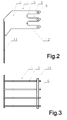
- Fig. 2 presents this device in a side view
- Fig. 3 presents this device in a top view with plate segments partially cut-out
- Fig. 4 presents the devices protecting rail cars against climbing before engaging
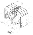
- Fig. 5 presents the devices protecting rail cars against climbing with bumpers of neighbouring rail cars in their position after engaging.
- a device protecting rail cars against climbing comprises a toothed element 1 fastened to the front wall 2 of a rail car.
- This toothed element 1 has four plate segments 3 working as vertical abutment elements 4.
- Each of these plate segments 3 has projected units, each comprising three-finger projections 5 having angle teeth 6 on their ends.
- notches 9 are wider than the diameter of the rods 8, and also the distance 10 between the opposite flat surfaces of the plate segments 3 is greater than their thickness.
- the width of the notches 9 in the shown embodiment is twice greater than the diameter of the rods 8, and the distance 10 between the opposite planes of the plate segments 3 is three times greater than their thickness. This great difference between these dimensions being compared ensures the better cooperation and engagement between cooperating toothed elements fastened on the front walls 2 of the connected rail cars.
- the toothed element 1 is fastened on the front wall 2 of a rail car by means of a vertical plate 11 having openings 12, 12a.
- the vertical plate 11 is an integral part of the toothed element 1.
- the plate segments 3 are shaped perpendicularly to this vertical plate 11.
- the notches 9 shaped between the finger projections 5 of the plate segments 3, have arc ends 13 forming an abutment surface designed to cooperate with the rods 8 of the toothed element 1 in the adjacent rail car.
- the rods 8 are embedded in coaxial openings 14 made in the teeth 6 of said plate segments 3.
- a shrinkage connection is used between the openings 14 and the rods 8 in order to protect the rods 8 against sliding out during a railway collision.
- Fig. 4 there is shown a set of railway bumpers 15 having devices protecting rail cars against climbing.
- the bumpers 15 are shown in the position of a resilient collision, in which toothed elements 1 are not yet in their geared position.
- the toothed elements 1 are designed to be fastened to the front walls 2 of rail cars so that the vertical plate 11 being an integral part of the toothed element 1 is pressed to the front wall 2 of the rail car by means of bolts fastening a body 16 of the bumper 15.
- the plate segments 3 of each toothed element 1 project above buffer plates 17 in such a manner that when the bumpers 15 are further deformed, both toothed elements 1 can be connected by mutually introducing the rods 8 into the notches 9.
- Fig. 5 there is shown a group of railway bumpers 15 having devices protecting rail cars against climbing in the situation of plastic deformation when toothed elements 1 are mutually interlocked.
- the toothed elements 1 of the neighbouring rail cars are deeply and tightly engaged together, sustained even with significant axial and angular displacements.
- the toothed elements 1 fastened by the bodies 16 of the bumpers 15 being in the mutual contact have the plate segments 3 shifted one in relation to another in the transverse direction by a half of a pitch so that the plate segments 3 located above the first bumper 15 get between plate segments situated above the second bumper 15. This displacement has been achieved by an asymmetric arrangement of the plate segments 3 in relation to the side edges 18, 19 of the vertical plate 11.
- the toothed elements 1 fastened by the bodies 16 of the brought into contact bumpers 15 have their plate segments 3 shifted one in relation to another in the vertical direction by a half of a pitch between the teeth 6 in such a way that the teeth 6 shaped on the plate segments 3 above one bumper 15 get between the teeth 6 formed on the plate segments above the second bumper 15.
- This displacement has been achieved by providing two pairs of openings 12, 12a in the vertical plate 11.
- This construction makes it also possible to use the same construction of a toothed element 1 on both sides of the set of bumpers 15 with providing a proper displacement of the cooperating plate segments 3.
- the toothed element 1 is mounted under one body 16 of the bumper 15 making use of the downward-shifted set of four openings 12, and the same toothed element 1 is mounted under the body 16 of the bumper of the neighbouring rail car using the set of four openings 12a shifted upwards.
Landscapes
- Engineering & Computer Science (AREA)
- Mechanical Engineering (AREA)
- Transportation (AREA)
- Vibration Dampers (AREA)
Abstract
Description
- This invention relates to a device protecting rail cars against climbing, especially during the final collision phase when shock absorbers are plastically deformed.
- From German patent application
DE102006050028 a device is known for protecting rail cars against climbing during a railway collision, said device comprising vertical and horizontal blocking elements projecting from the front walls of these rail cars. These vertical and horizontal blocking elements are firmly connected together and they form a grate-like structure made of flat ribbons forming cells opened in a direction in which a rail car is moving. These open cells are made in such a way that they can be deformed in their longitudinal direction to ensure in this way their mutual penetration and meshing between the blocking elements of neighbouring rail cars. - From
EP2193970 a buffer is also known protecting rail cars against climbing during a railway collision, said buffer comprising a coupling element having teeth shaped on its outer surface. This coupling element is shaped as a flat plate connected with the front of a rail car and it has toothed projections arranged on its concave surface. - From patent specification
US7694633 the element protecting rail cars against climbing during a railway collision is also known. This element is fastened to the front of the rail car at a determined height so as to enable its cooperation with a suitable element of the neighbouring rail car in case of a collision. In a middle part of this element, there is made a central cut-out limited by an upper plate, a lower plate and two side centring surfaces. - From patent specification
EP 2163454 a railway engine is also known comprising a device protecting rail cars against climbing during a railway collision. Said device has a supporting element fastened slidably on a chassis of a railway engine over its bumpers. An end part of that device is purpose-built to be engaged with the front surface of a nearby railway car during a collision. - It is an aim of this invention to create a device protecting rail cars against climbing during a railway collision. This device ensures a great rigidity in a transverse direction, as well as easy mashing with a protecting device fastened in the front part of the neighbouring rail car even during a substantial linear and angular displacement of these meshing devices. An additional aim of the solution according to the invention is to enable easier modernisation of the existing railway cars.
- The device protecting against climbing of the invention comprises a toothed element fastened to the front wall of a rail car in which vertical abutment elements are connected with horizontal abutment elements. The device is characterized in that the toothed element comprises at least three distant vertical abutment elements made as plate segments ended with teeth, and in the teeth of said plate segments there are fastened horizontal abutment elements made as rods. Notches formed in the plate segments have their width greater than a thickness of rods forming the horizontal abutment elements, and the distance between the opposite flat surfaces of the plate segments is greater than the thickness of those plate segments. Advantageously, the horizontal abutment elements have a form of rods of circular cross section.
- Advantageously, the toothed segment is jointed with the vertical plate.
- Advantageously, the plate segments of the toothed element are placed perpendicularly to the vertical plate.
- Advantageously, the toothed element's vertical plate is fastened to the front wall of the rail car through the bumper body. More advantageously, the toothed element's vertical plate is fastened to the front wall of the rail car and compressed to it by fixing bolts of the bumper body.
- Advantageously, rods forming the horizontal abutment elements are embedded at the horizontal, coaxial openings made in toothed plate segments.
- Advantageously, the vertical plate of the toothed element comprises two sets of openings enabling fastening it in different positions under the bumper body.
- Advantageously, the plate segments being the vertical abutment elements are placed asymmetrically in relation to side edges of the vertical plate.
- Thanks to placing toothed elements having many distant vertical abutment elements made as plate segments ended with teeth having horizontal rod abutment elements on the opposite front walls of the connected railway cars they can be easy interengaged even by greater axial and angular displacements. Moreover, when the devices according to the invention are engaged, the rail cars being connected are protected against climbing, as well as against running aside from the railway tracks line.
- By connecting the toothed element with the vertical plate and fastening of this vertical plate to the front wall of the rail car by means of the bumper body, the existing rolling stock comprising hitherto no device protecting against climbing may be easily modernized.
- Thanks to the rods embedding in the openings of the teeth of the plate segments, these segments are connected one with another, which allows to evenly distribute a force between them when the device according to this invention is in action, especially for such collisions in which a force acting between neighbouring rail cars is not parallel to an axis of railway tracks.
- The present invention is illustrated in its embodiments in a drawing, in which
Fig. 1 presents in a perspective view a device protecting rail cars against climbing,Fig. 2 presents this device in a side view,Fig. 3 presents this device in a top view with plate segments partially cut-out,Fig. 4 presents the devices protecting rail cars against climbing before engaging, andFig. 5 presents the devices protecting rail cars against climbing with bumpers of neighbouring rail cars in their position after engaging. - As it is shown in the embodiment in
Fig. 1 , a device protecting rail cars against climbing according to this invention comprises atoothed element 1 fastened to thefront wall 2 of a rail car. Thistoothed element 1 has fourplate segments 3 working asvertical abutment elements 4. Each of theseplate segments 3 has projected units, each comprising three-finger projections 5 havingangle teeth 6 on their ends. - Three
circular rods 8 embedded in theangle teeth 6 of each of the fourplate segments 3 work ashorizontal abutment elements 7. In order to ensure the cooperation between thetoothed element 1 and a similar toothed element fastened to the front wall of another rail car,notches 9 are wider than the diameter of therods 8, and also thedistance 10 between the opposite flat surfaces of theplate segments 3 is greater than their thickness. The width of thenotches 9 in the shown embodiment is twice greater than the diameter of therods 8, and thedistance 10 between the opposite planes of theplate segments 3 is three times greater than their thickness. This great difference between these dimensions being compared ensures the better cooperation and engagement between cooperating toothed elements fastened on thefront walls 2 of the connected rail cars. - The
toothed element 1 is fastened on thefront wall 2 of a rail car by means of avertical plate 11 havingopenings vertical plate 11 is an integral part of thetoothed element 1. In the upper part of theplate 11 above theopenings plate segments 3 are shaped perpendicularly to thisvertical plate 11. - As it is shown in the side view in
Fig. 2 , thenotches 9 shaped between thefinger projections 5 of theplate segments 3, havearc ends 13 forming an abutment surface designed to cooperate with therods 8 of thetoothed element 1 in the adjacent rail car. - As illustrated in
Fig. 3 , therods 8 are embedded incoaxial openings 14 made in theteeth 6 ofsaid plate segments 3. - A shrinkage connection is used between the
openings 14 and therods 8 in order to protect therods 8 against sliding out during a railway collision. - In
Fig. 4 there is shown a set ofrailway bumpers 15 having devices protecting rail cars against climbing. In this embodiment, thebumpers 15 are shown in the position of a resilient collision, in whichtoothed elements 1 are not yet in their geared position. Thetoothed elements 1 are designed to be fastened to thefront walls 2 of rail cars so that thevertical plate 11 being an integral part of thetoothed element 1 is pressed to thefront wall 2 of the rail car by means of bolts fastening abody 16 of thebumper 15. Theplate segments 3 of eachtoothed element 1 project abovebuffer plates 17 in such a manner that when thebumpers 15 are further deformed, bothtoothed elements 1 can be connected by mutually introducing therods 8 into thenotches 9. - In
Fig. 5 there is shown a group ofrailway bumpers 15 having devices protecting rail cars against climbing in the situation of plastic deformation whentoothed elements 1 are mutually interlocked. In this situation, thetoothed elements 1 of the neighbouring rail cars are deeply and tightly engaged together, sustained even with significant axial and angular displacements. In order to increase the reliability of the coupling betweentoothed elements 1 of the neighbouring rail cars, thetoothed elements 1 fastened by thebodies 16 of thebumpers 15 being in the mutual contact have theplate segments 3 shifted one in relation to another in the transverse direction by a half of a pitch so that theplate segments 3 located above thefirst bumper 15 get between plate segments situated above thesecond bumper 15. This displacement has been achieved by an asymmetric arrangement of theplate segments 3 in relation to theside edges vertical plate 11. - By increasing the distance of the
plate 3 from oneside edge 19, a possibility has been obtained to use the same construction of thetoothed element 1 at both sides of the set ofbumpers 15 together with the proper off-set of the mutually co-operatingplate segments 3. - Similarly, in order to obtain the more reliable coupling between the
toothed elements 1 of the neighbouring rail cars, thetoothed elements 1 fastened by thebodies 16 of the brought intocontact bumpers 15 have theirplate segments 3 shifted one in relation to another in the vertical direction by a half of a pitch between theteeth 6 in such a way that theteeth 6 shaped on theplate segments 3 above onebumper 15 get between theteeth 6 formed on the plate segments above thesecond bumper 15. This displacement has been achieved by providing two pairs ofopenings vertical plate 11. This construction makes it also possible to use the same construction of atoothed element 1 on both sides of the set ofbumpers 15 with providing a proper displacement of the cooperatingplate segments 3. In order to achieve such a displacement, thetoothed element 1 is mounted under onebody 16 of thebumper 15 making use of the downward-shifted set of fouropenings 12, and thesame toothed element 1 is mounted under thebody 16 of the bumper of the neighbouring rail car using the set of fouropenings 12a shifted upwards.
Claims (9)
- A device protecting rail cars against climbing during a railway collision, comprising a toothed element (1) fastened to the front wall of the rail car, in which vertical abutment elements (4) are connected with horizontal abutment elements (7), characterized in that the toothed element (1) comprises at least three distant vertical abutment elements (4) shaped as plate segments (3) ended with teeth (6), and in the teeth (6) of the mentioned plate segments (3) there are embedded the horizontal abutment elements (7) shaped as rods (8), whereas the width of notches (9) formed in the plate segments (3) is greater than the thickness of the rods (8) forming the horizontal abutment elements (7), and the distance (10) between the opposite planes of the plate segments (3) is greater than the thickness of these plate segments (3).
- A device according to Claim 1 wherein the horizontal abutment elements (7) are made as the rods (8) having a circular section.
- A device according to Claim 1 or 2 wherein a toothed element (1) is joined with a vertical plate (11).
- A device according to Claim 3 wherein the plate segments (3) of the toothed element (1) are perpendicular to the vertical plate (11).
- A device according to Claim 3 or 4 wherein the vertical plate (11) of the toothed element (1) is fastened to the front wall (2) of the rail car by a body (16) of a bumper (15).
- A device according to Claim 5 wherein the vertical plate (11) of the toothed element (1) is fastened to the front wall (2) of the rail car and is pressed to the front wall (2) by means of bolts fastening the body (16) of the bumper (15).
- A device according to Claims 1 - 6 wherein the rods (8) being the horizontal abutment elements (7) are embedded in coaxial horizontal openings (14) made in the teeth (6) of the plate segments (3).
- A device according to Claims 5 - 6 wherein the vertical plate (11) of the toothed element (1) has two sets of openings (12, 12a) to be fastened below the body (16) of the bumper (15) in different positions.
- A device according to Claim 1 or 8 wherein the plate segments (3) are asymmetrically situated in relation to side edges (18, 19) of the vertical plate (11).
Applications Claiming Priority (1)
| Application Number | Priority Date | Filing Date | Title |
|---|---|---|---|
| PL401484A PL222364B1 (en) | 2012-11-06 | 2012-11-06 | Device to prevent climbing railway wagons at each other during the collision |
Publications (2)
| Publication Number | Publication Date |
|---|---|
| EP2727792A1 true EP2727792A1 (en) | 2014-05-07 |
| EP2727792B1 EP2727792B1 (en) | 2016-02-17 |
Family
ID=49578247
Family Applications (1)
| Application Number | Title | Priority Date | Filing Date |
|---|---|---|---|
| EP13461556.6A Active EP2727792B1 (en) | 2012-11-06 | 2013-11-06 | Device protecting rail cars against climbing in case of a railway collision |
Country Status (2)
| Country | Link |
|---|---|
| EP (1) | EP2727792B1 (en) |
| PL (1) | PL222364B1 (en) |
Cited By (3)
| Publication number | Priority date | Publication date | Assignee | Title |
|---|---|---|---|---|
| EP2998181A1 (en) * | 2014-09-17 | 2016-03-23 | Bombardier Transportation GmbH | Rail vehicle comprising a fastening assembly for a mounted part and method for fixing a mounted part to a vehicle body of a rail vehicle |
| AT521787A4 (en) * | 2019-03-28 | 2020-07-15 | Siemens Mobility Austria Gmbh | Climbing protection device |
| WO2022069052A1 (en) * | 2020-10-01 | 2022-04-07 | Falk Schneider | Energy consumption-reduced override protection |
Citations (6)
| Publication number | Priority date | Publication date | Assignee | Title |
|---|---|---|---|---|
| FR2531393A1 (en) * | 1982-08-03 | 1984-02-10 | Scharfenbergkupplung Gmbh | Railway vehicle anti-telescoping device |
| DE102006050028A1 (en) | 2006-10-24 | 2008-04-30 | Sieghard Schneider | Anti-climbing protective device for rail vehicles, has molded parts, which projects out of vehicle front, and has catch made of cells that are formed by level rods in direction of travel |
| DE102008048244B3 (en) * | 2008-09-16 | 2009-09-10 | Vossloh Locomotives Gmbh | Anti-climbing device i.e. locomotive frame, for buffer i.e. crash buffer, on locomotive for impact absorption, has rope retained by supporting strut, and rail with rope attached with retainers of impacting buffer plate during collision |
| EP2163454A1 (en) | 2008-09-16 | 2010-03-17 | Vossloh Locomotives GmbH | Anti-climb device for locomotive bumpers |
| US7694633B2 (en) | 2003-06-13 | 2010-04-13 | Siemens Transportation Systems Gmbh & Co Kg | Anti-climbing device for railay carriages |
| EP2193970A2 (en) | 2008-12-02 | 2010-06-09 | Bombardier Transportation GmbH | Buffer for a railway vehicle |
-
2012
- 2012-11-06 PL PL401484A patent/PL222364B1/en unknown
-
2013
- 2013-11-06 EP EP13461556.6A patent/EP2727792B1/en active Active
Patent Citations (6)
| Publication number | Priority date | Publication date | Assignee | Title |
|---|---|---|---|---|
| FR2531393A1 (en) * | 1982-08-03 | 1984-02-10 | Scharfenbergkupplung Gmbh | Railway vehicle anti-telescoping device |
| US7694633B2 (en) | 2003-06-13 | 2010-04-13 | Siemens Transportation Systems Gmbh & Co Kg | Anti-climbing device for railay carriages |
| DE102006050028A1 (en) | 2006-10-24 | 2008-04-30 | Sieghard Schneider | Anti-climbing protective device for rail vehicles, has molded parts, which projects out of vehicle front, and has catch made of cells that are formed by level rods in direction of travel |
| DE102008048244B3 (en) * | 2008-09-16 | 2009-09-10 | Vossloh Locomotives Gmbh | Anti-climbing device i.e. locomotive frame, for buffer i.e. crash buffer, on locomotive for impact absorption, has rope retained by supporting strut, and rail with rope attached with retainers of impacting buffer plate during collision |
| EP2163454A1 (en) | 2008-09-16 | 2010-03-17 | Vossloh Locomotives GmbH | Anti-climb device for locomotive bumpers |
| EP2193970A2 (en) | 2008-12-02 | 2010-06-09 | Bombardier Transportation GmbH | Buffer for a railway vehicle |
Cited By (6)
| Publication number | Priority date | Publication date | Assignee | Title |
|---|---|---|---|---|
| EP2998181A1 (en) * | 2014-09-17 | 2016-03-23 | Bombardier Transportation GmbH | Rail vehicle comprising a fastening assembly for a mounted part and method for fixing a mounted part to a vehicle body of a rail vehicle |
| AT521787A4 (en) * | 2019-03-28 | 2020-07-15 | Siemens Mobility Austria Gmbh | Climbing protection device |
| AT521787B1 (en) * | 2019-03-28 | 2020-07-15 | Siemens Mobility Austria Gmbh | Climbing protection device |
| WO2020193257A1 (en) * | 2019-03-28 | 2020-10-01 | Siemens Mobility Austria Gmbh | Anti-climbing device |
| RU2767080C1 (en) * | 2019-03-28 | 2022-03-16 | Сименс Мобилити Аустриа Гмбх | Anti-runaway protection device for a rail vehicle |
| WO2022069052A1 (en) * | 2020-10-01 | 2022-04-07 | Falk Schneider | Energy consumption-reduced override protection |
Also Published As
| Publication number | Publication date |
|---|---|
| PL222364B1 (en) | 2016-07-29 |
| EP2727792B1 (en) | 2016-02-17 |
| PL401484A1 (en) | 2014-05-12 |
Similar Documents
| Publication | Publication Date | Title |
|---|---|---|
| EP2727792B1 (en) | Device protecting rail cars against climbing in case of a railway collision | |
| KR20150132142A (en) | Bumper beam | |
| EP3880919B1 (en) | Roadway barrier apparatus | |
| EP2062787A8 (en) | Shock absorbing structure for vehicle | |
| US20150175208A1 (en) | Vehicle frame member structure with excellent impact resistance performance | |
| CN201172786Y (en) | Adjustable rail-fixing machine | |
| EP2455242A1 (en) | Assembly for forming the bellows of a transition or the side wall between two vehicles with a jointed connection | |
| KR20180095078A (en) | bumper | |
| CN103192845B (en) | The anti-bias energy absorption device of a kind of anti-creep | |
| US20160347371A1 (en) | Metal beam with a limited bending angle | |
| US9988778B2 (en) | Barrier wall element | |
| RU207843U1 (en) | ANTI-RUNNING PROTECTION DEVICE FOR A RAIL VEHICLE | |
| EP1880913A3 (en) | Rail maintenance vehicle with impact protection | |
| US9815483B2 (en) | Ride-up protection means | |
| CN113613982B (en) | Anti-climbing device for railway vehicle | |
| CA2864243A1 (en) | Rolling stock | |
| EP2233638A3 (en) | Machine for positioning and squaring crossties of railway tracks | |
| KR102148556B1 (en) | Device for producing at least one undercut in a slotted or closed profiled sheet section | |
| US9963049B2 (en) | Rail pair for a vehicle seat | |
| WO2017178158A1 (en) | Profiled bearing and rail system | |
| CN218373528U (en) | High-toughness safe guardrail | |
| CA2459185A1 (en) | Toeboard system for scaffolding | |
| CN202787063U (en) | Bridge expansion device with function of lowering passing vehicle impact | |
| KR20090126353A (en) | Absorbing reinforcement for guardrail and it's manufacturing method and it's absorbing structure | |
| WO2020234252A1 (en) | Energy dissipation device |
Legal Events
| Date | Code | Title | Description |
|---|---|---|---|
| PUAI | Public reference made under article 153(3) epc to a published international application that has entered the european phase |
Free format text: ORIGINAL CODE: 0009012 |
|
| 17P | Request for examination filed |
Effective date: 20131106 |
|
| AK | Designated contracting states |
Kind code of ref document: A1 Designated state(s): AL AT BE BG CH CY CZ DE DK EE ES FI FR GB GR HR HU IE IS IT LI LT LU LV MC MK MT NL NO PL PT RO RS SE SI SK SM TR |
|
| AX | Request for extension of the european patent |
Extension state: BA ME |
|
| 17P | Request for examination filed |
Effective date: 20140922 |
|
| RBV | Designated contracting states (corrected) |
Designated state(s): AL AT BE BG CH CY CZ DE DK EE ES FI FR GB GR HR HU IE IS IT LI LT LU LV MC MK MT NL NO PL PT RO RS SE SI SK SM TR |
|
| RAP1 | Party data changed (applicant data changed or rights of an application transferred) |
Owner name: AXTONE SPOLKA AKCYJNA |
|
| GRAP | Despatch of communication of intention to grant a patent |
Free format text: ORIGINAL CODE: EPIDOSNIGR1 |
|
| INTG | Intention to grant announced |
Effective date: 20150721 |
|
| GRAS | Grant fee paid |
Free format text: ORIGINAL CODE: EPIDOSNIGR3 |
|
| INTG | Intention to grant announced |
Effective date: 20151203 |
|
| GRAA | (expected) grant |
Free format text: ORIGINAL CODE: 0009210 |
|
| AK | Designated contracting states |
Kind code of ref document: B1 Designated state(s): AL AT BE BG CH CY CZ DE DK EE ES FI FR GB GR HR HU IE IS IT LI LT LU LV MC MK MT NL NO PL PT RO RS SE SI SK SM TR |
|
| REG | Reference to a national code |
Ref country code: GB Ref legal event code: FG4D |
|
| REG | Reference to a national code |
Ref country code: CH Ref legal event code: EP |
|
| REG | Reference to a national code |
Ref country code: IE Ref legal event code: FG4D |
|
| REG | Reference to a national code |
Ref country code: AT Ref legal event code: REF Ref document number: 775499 Country of ref document: AT Kind code of ref document: T Effective date: 20160315 |
|
| REG | Reference to a national code |
Ref country code: DE Ref legal event code: R096 Ref document number: 602013005043 Country of ref document: DE |
|
| REG | Reference to a national code |
Ref country code: RO Ref legal event code: EPE |
|
| REG | Reference to a national code |
Ref country code: NL Ref legal event code: MP Effective date: 20160217 |
|
| REG | Reference to a national code |
Ref country code: LT Ref legal event code: MG4D |
|
| REG | Reference to a national code |
Ref country code: AT Ref legal event code: MK05 Ref document number: 775499 Country of ref document: AT Kind code of ref document: T Effective date: 20160217 |
|
| PG25 | Lapsed in a contracting state [announced via postgrant information from national office to epo] |
Ref country code: GR Free format text: LAPSE BECAUSE OF FAILURE TO SUBMIT A TRANSLATION OF THE DESCRIPTION OR TO PAY THE FEE WITHIN THE PRESCRIBED TIME-LIMIT Effective date: 20160518 Ref country code: ES Free format text: LAPSE BECAUSE OF FAILURE TO SUBMIT A TRANSLATION OF THE DESCRIPTION OR TO PAY THE FEE WITHIN THE PRESCRIBED TIME-LIMIT Effective date: 20160217 Ref country code: NO Free format text: LAPSE BECAUSE OF FAILURE TO SUBMIT A TRANSLATION OF THE DESCRIPTION OR TO PAY THE FEE WITHIN THE PRESCRIBED TIME-LIMIT Effective date: 20160517 Ref country code: FI Free format text: LAPSE BECAUSE OF FAILURE TO SUBMIT A TRANSLATION OF THE DESCRIPTION OR TO PAY THE FEE WITHIN THE PRESCRIBED TIME-LIMIT Effective date: 20160217 Ref country code: HR Free format text: LAPSE BECAUSE OF FAILURE TO SUBMIT A TRANSLATION OF THE DESCRIPTION OR TO PAY THE FEE WITHIN THE PRESCRIBED TIME-LIMIT Effective date: 20160217 Ref country code: IT Free format text: LAPSE BECAUSE OF FAILURE TO SUBMIT A TRANSLATION OF THE DESCRIPTION OR TO PAY THE FEE WITHIN THE PRESCRIBED TIME-LIMIT Effective date: 20160217 |
|
| REG | Reference to a national code |
Ref country code: FR Ref legal event code: PLFP Year of fee payment: 4 |
|
| PG25 | Lapsed in a contracting state [announced via postgrant information from national office to epo] |
Ref country code: AT Free format text: LAPSE BECAUSE OF FAILURE TO SUBMIT A TRANSLATION OF THE DESCRIPTION OR TO PAY THE FEE WITHIN THE PRESCRIBED TIME-LIMIT Effective date: 20160217 Ref country code: LV Free format text: LAPSE BECAUSE OF FAILURE TO SUBMIT A TRANSLATION OF THE DESCRIPTION OR TO PAY THE FEE WITHIN THE PRESCRIBED TIME-LIMIT Effective date: 20160217 Ref country code: PT Free format text: LAPSE BECAUSE OF FAILURE TO SUBMIT A TRANSLATION OF THE DESCRIPTION OR TO PAY THE FEE WITHIN THE PRESCRIBED TIME-LIMIT Effective date: 20160617 Ref country code: NL Free format text: LAPSE BECAUSE OF FAILURE TO SUBMIT A TRANSLATION OF THE DESCRIPTION OR TO PAY THE FEE WITHIN THE PRESCRIBED TIME-LIMIT Effective date: 20160217 Ref country code: LT Free format text: LAPSE BECAUSE OF FAILURE TO SUBMIT A TRANSLATION OF THE DESCRIPTION OR TO PAY THE FEE WITHIN THE PRESCRIBED TIME-LIMIT Effective date: 20160217 Ref country code: SE Free format text: LAPSE BECAUSE OF FAILURE TO SUBMIT A TRANSLATION OF THE DESCRIPTION OR TO PAY THE FEE WITHIN THE PRESCRIBED TIME-LIMIT Effective date: 20160217 Ref country code: RS Free format text: LAPSE BECAUSE OF FAILURE TO SUBMIT A TRANSLATION OF THE DESCRIPTION OR TO PAY THE FEE WITHIN THE PRESCRIBED TIME-LIMIT Effective date: 20160217 Ref country code: PL Free format text: LAPSE BECAUSE OF FAILURE TO SUBMIT A TRANSLATION OF THE DESCRIPTION OR TO PAY THE FEE WITHIN THE PRESCRIBED TIME-LIMIT Effective date: 20160217 |
|
| REG | Reference to a national code |
Ref country code: SK Ref legal event code: T3 Ref document number: E 21003 Country of ref document: SK |
|
| PG25 | Lapsed in a contracting state [announced via postgrant information from national office to epo] |
Ref country code: DK Free format text: LAPSE BECAUSE OF FAILURE TO SUBMIT A TRANSLATION OF THE DESCRIPTION OR TO PAY THE FEE WITHIN THE PRESCRIBED TIME-LIMIT Effective date: 20160217 Ref country code: EE Free format text: LAPSE BECAUSE OF FAILURE TO SUBMIT A TRANSLATION OF THE DESCRIPTION OR TO PAY THE FEE WITHIN THE PRESCRIBED TIME-LIMIT Effective date: 20160217 |
|
| REG | Reference to a national code |
Ref country code: DE Ref legal event code: R097 Ref document number: 602013005043 Country of ref document: DE |
|
| PG25 | Lapsed in a contracting state [announced via postgrant information from national office to epo] |
Ref country code: SM Free format text: LAPSE BECAUSE OF FAILURE TO SUBMIT A TRANSLATION OF THE DESCRIPTION OR TO PAY THE FEE WITHIN THE PRESCRIBED TIME-LIMIT Effective date: 20160217 |
|
| PLBE | No opposition filed within time limit |
Free format text: ORIGINAL CODE: 0009261 |
|
| STAA | Information on the status of an ep patent application or granted ep patent |
Free format text: STATUS: NO OPPOSITION FILED WITHIN TIME LIMIT |
|
| PG25 | Lapsed in a contracting state [announced via postgrant information from national office to epo] |
Ref country code: BE Free format text: LAPSE BECAUSE OF FAILURE TO SUBMIT A TRANSLATION OF THE DESCRIPTION OR TO PAY THE FEE WITHIN THE PRESCRIBED TIME-LIMIT Effective date: 20160217 |
|
| 26N | No opposition filed |
Effective date: 20161118 |
|
| PG25 | Lapsed in a contracting state [announced via postgrant information from national office to epo] |
Ref country code: SI Free format text: LAPSE BECAUSE OF FAILURE TO SUBMIT A TRANSLATION OF THE DESCRIPTION OR TO PAY THE FEE WITHIN THE PRESCRIBED TIME-LIMIT Effective date: 20160217 Ref country code: BG Free format text: LAPSE BECAUSE OF FAILURE TO SUBMIT A TRANSLATION OF THE DESCRIPTION OR TO PAY THE FEE WITHIN THE PRESCRIBED TIME-LIMIT Effective date: 20160517 |
|
| REG | Reference to a national code |
Ref country code: CH Ref legal event code: PL |
|
| PG25 | Lapsed in a contracting state [announced via postgrant information from national office to epo] |
Ref country code: LI Free format text: LAPSE BECAUSE OF NON-PAYMENT OF DUE FEES Effective date: 20161130 Ref country code: CH Free format text: LAPSE BECAUSE OF NON-PAYMENT OF DUE FEES Effective date: 20161130 |
|
| REG | Reference to a national code |
Ref country code: CH Ref legal event code: AECN Free format text: DAS PATENT IST AUFGRUND DES WEITERBEHANDLUNGSANTRAGS VOM 08.08.2017 REAKTIVIERT WORDEN. Ref country code: CH Ref legal event code: NV Representative=s name: CRONIN INTELLECTUAL PROPERTY, CH |
|
| REG | Reference to a national code |
Ref country code: IE Ref legal event code: MM4A |
|
| PG25 | Lapsed in a contracting state [announced via postgrant information from national office to epo] |
Ref country code: LU Free format text: LAPSE BECAUSE OF NON-PAYMENT OF DUE FEES Effective date: 20161130 |
|
| PG25 | Lapsed in a contracting state [announced via postgrant information from national office to epo] |
Ref country code: CH Free format text: LAPSE BECAUSE OF NON-PAYMENT OF DUE FEES Effective date: 20161130 Ref country code: LI Free format text: LAPSE BECAUSE OF NON-PAYMENT OF DUE FEES Effective date: 20161130 |
|
| PGRI | Patent reinstated in contracting state [announced from national office to epo] |
Ref country code: CH Effective date: 20170811 Ref country code: LI Effective date: 20170811 |
|
| REG | Reference to a national code |
Ref country code: FR Ref legal event code: PLFP Year of fee payment: 5 |
|
| PG25 | Lapsed in a contracting state [announced via postgrant information from national office to epo] |
Ref country code: IE Free format text: LAPSE BECAUSE OF NON-PAYMENT OF DUE FEES Effective date: 20161106 |
|
| REG | Reference to a national code |
Ref country code: CH Ref legal event code: PCAR Free format text: NEW ADDRESS: CHEMIN DE LA VUARPILLIERE 29, 1260 NYON (CH) |
|
| PG25 | Lapsed in a contracting state [announced via postgrant information from national office to epo] |
Ref country code: HU Free format text: LAPSE BECAUSE OF FAILURE TO SUBMIT A TRANSLATION OF THE DESCRIPTION OR TO PAY THE FEE WITHIN THE PRESCRIBED TIME-LIMIT; INVALID AB INITIO Effective date: 20131106 Ref country code: CY Free format text: LAPSE BECAUSE OF FAILURE TO SUBMIT A TRANSLATION OF THE DESCRIPTION OR TO PAY THE FEE WITHIN THE PRESCRIBED TIME-LIMIT Effective date: 20160217 |
|
| PG25 | Lapsed in a contracting state [announced via postgrant information from national office to epo] |
Ref country code: MC Free format text: LAPSE BECAUSE OF FAILURE TO SUBMIT A TRANSLATION OF THE DESCRIPTION OR TO PAY THE FEE WITHIN THE PRESCRIBED TIME-LIMIT Effective date: 20160217 Ref country code: IS Free format text: LAPSE BECAUSE OF FAILURE TO SUBMIT A TRANSLATION OF THE DESCRIPTION OR TO PAY THE FEE WITHIN THE PRESCRIBED TIME-LIMIT Effective date: 20160217 Ref country code: MK Free format text: LAPSE BECAUSE OF FAILURE TO SUBMIT A TRANSLATION OF THE DESCRIPTION OR TO PAY THE FEE WITHIN THE PRESCRIBED TIME-LIMIT Effective date: 20160217 |
|
| GBPC | Gb: european patent ceased through non-payment of renewal fee |
Effective date: 20171106 |
|
| PG25 | Lapsed in a contracting state [announced via postgrant information from national office to epo] |
Ref country code: MT Free format text: LAPSE BECAUSE OF NON-PAYMENT OF DUE FEES Effective date: 20161106 |
|
| PG25 | Lapsed in a contracting state [announced via postgrant information from national office to epo] |
Ref country code: AL Free format text: LAPSE BECAUSE OF FAILURE TO SUBMIT A TRANSLATION OF THE DESCRIPTION OR TO PAY THE FEE WITHIN THE PRESCRIBED TIME-LIMIT Effective date: 20160217 Ref country code: TR Free format text: LAPSE BECAUSE OF FAILURE TO SUBMIT A TRANSLATION OF THE DESCRIPTION OR TO PAY THE FEE WITHIN THE PRESCRIBED TIME-LIMIT Effective date: 20160217 |
|
| PG25 | Lapsed in a contracting state [announced via postgrant information from national office to epo] |
Ref country code: GB Free format text: LAPSE BECAUSE OF NON-PAYMENT OF DUE FEES Effective date: 20171106 |
|
| PGFP | Annual fee paid to national office [announced via postgrant information from national office to epo] |
Ref country code: RO Payment date: 20201105 Year of fee payment: 8 Ref country code: FR Payment date: 20201021 Year of fee payment: 8 Ref country code: CZ Payment date: 20201021 Year of fee payment: 8 |
|
| PGFP | Annual fee paid to national office [announced via postgrant information from national office to epo] |
Ref country code: SK Payment date: 20201026 Year of fee payment: 8 |
|
| REG | Reference to a national code |
Ref country code: SK Ref legal event code: MM4A Ref document number: E 21003 Country of ref document: SK Effective date: 20211106 |
|
| PG25 | Lapsed in a contracting state [announced via postgrant information from national office to epo] |
Ref country code: SK Free format text: LAPSE BECAUSE OF NON-PAYMENT OF DUE FEES Effective date: 20211106 Ref country code: RO Free format text: LAPSE BECAUSE OF NON-PAYMENT OF DUE FEES Effective date: 20211106 Ref country code: CZ Free format text: LAPSE BECAUSE OF NON-PAYMENT OF DUE FEES Effective date: 20211106 |
|
| PG25 | Lapsed in a contracting state [announced via postgrant information from national office to epo] |
Ref country code: FR Free format text: LAPSE BECAUSE OF NON-PAYMENT OF DUE FEES Effective date: 20211130 |
|
| P01 | Opt-out of the competence of the unified patent court (upc) registered |
Effective date: 20230528 |
|
| PGFP | Annual fee paid to national office [announced via postgrant information from national office to epo] |
Ref country code: DE Payment date: 20231019 Year of fee payment: 11 Ref country code: CH Payment date: 20231201 Year of fee payment: 11 |