EP2727770B1 - Automotive reconfigurable overhead light assembly - Google Patents
Automotive reconfigurable overhead light assembly Download PDFInfo
- Publication number
- EP2727770B1 EP2727770B1 EP13191698.3A EP13191698A EP2727770B1 EP 2727770 B1 EP2727770 B1 EP 2727770B1 EP 13191698 A EP13191698 A EP 13191698A EP 2727770 B1 EP2727770 B1 EP 2727770B1
- Authority
- EP
- European Patent Office
- Prior art keywords
- electrical
- printed circuit
- light source
- terminals
- switch
- Prior art date
- Legal status (The legal status is an assumption and is not a legal conclusion. Google has not performed a legal analysis and makes no representation as to the accuracy of the status listed.)
- Active
Links
- 239000004020 conductor Substances 0.000 claims description 6
- 101001024685 Pandinus imperator Pandinin-2 Proteins 0.000 description 6
- 238000000034 method Methods 0.000 description 5
- 101001128814 Pandinus imperator Pandinin-1 Proteins 0.000 description 4
- 239000000956 alloy Substances 0.000 description 2
- 229910045601 alloy Inorganic materials 0.000 description 2
- 230000000712 assembly Effects 0.000 description 2
- 238000000429 assembly Methods 0.000 description 2
- 230000008878 coupling Effects 0.000 description 2
- 238000010168 coupling process Methods 0.000 description 2
- 238000005859 coupling reaction Methods 0.000 description 2
- 229910052736 halogen Inorganic materials 0.000 description 2
- 150000002367 halogens Chemical class 0.000 description 2
- 239000004417 polycarbonate Substances 0.000 description 2
- 229920000515 polycarbonate Polymers 0.000 description 2
- -1 polypropylene Polymers 0.000 description 2
- 238000005476 soldering Methods 0.000 description 2
- 229930040373 Paraformaldehyde Natural products 0.000 description 1
- 239000004743 Polypropylene Substances 0.000 description 1
- 238000002788 crimping Methods 0.000 description 1
- 238000010586 diagram Methods 0.000 description 1
- 238000005286 illumination Methods 0.000 description 1
- 238000004519 manufacturing process Methods 0.000 description 1
- 239000002184 metal Substances 0.000 description 1
- 238000012986 modification Methods 0.000 description 1
- 230000004048 modification Effects 0.000 description 1
- 230000010287 polarization Effects 0.000 description 1
- 229920006324 polyoxymethylene Polymers 0.000 description 1
- 229920001155 polypropylene Polymers 0.000 description 1
Images


Classifications
-
- B—PERFORMING OPERATIONS; TRANSPORTING
- B60—VEHICLES IN GENERAL
- B60Q—ARRANGEMENT OF SIGNALLING OR LIGHTING DEVICES, THE MOUNTING OR SUPPORTING THEREOF OR CIRCUITS THEREFOR, FOR VEHICLES IN GENERAL
- B60Q3/00—Arrangement of lighting devices for vehicle interiors; Lighting devices specially adapted for vehicle interiors
- B60Q3/80—Circuits; Control arrangements
-
- B—PERFORMING OPERATIONS; TRANSPORTING
- B60—VEHICLES IN GENERAL
- B60Q—ARRANGEMENT OF SIGNALLING OR LIGHTING DEVICES, THE MOUNTING OR SUPPORTING THEREOF OR CIRCUITS THEREFOR, FOR VEHICLES IN GENERAL
- B60Q3/00—Arrangement of lighting devices for vehicle interiors; Lighting devices specially adapted for vehicle interiors
- B60Q3/50—Mounting arrangements
- B60Q3/51—Mounting arrangements for mounting lighting devices onto vehicle interior, e.g. onto ceiling or floor
-
- B—PERFORMING OPERATIONS; TRANSPORTING
- B60—VEHICLES IN GENERAL
- B60Q—ARRANGEMENT OF SIGNALLING OR LIGHTING DEVICES, THE MOUNTING OR SUPPORTING THEREOF OR CIRCUITS THEREFOR, FOR VEHICLES IN GENERAL
- B60Q3/00—Arrangement of lighting devices for vehicle interiors; Lighting devices specially adapted for vehicle interiors
- B60Q3/70—Arrangement of lighting devices for vehicle interiors; Lighting devices specially adapted for vehicle interiors characterised by the purpose
- B60Q3/74—Arrangement of lighting devices for vehicle interiors; Lighting devices specially adapted for vehicle interiors characterised by the purpose for overall compartment lighting; for overall compartment lighting in combination with specific lighting, e.g. room lamps with reading lamps
-
- B—PERFORMING OPERATIONS; TRANSPORTING
- B60—VEHICLES IN GENERAL
- B60Q—ARRANGEMENT OF SIGNALLING OR LIGHTING DEVICES, THE MOUNTING OR SUPPORTING THEREOF OR CIRCUITS THEREFOR, FOR VEHICLES IN GENERAL
- B60Q3/00—Arrangement of lighting devices for vehicle interiors; Lighting devices specially adapted for vehicle interiors
- B60Q3/80—Circuits; Control arrangements
- B60Q3/82—Switches specially adapted for vehicle interior lighting, e.g. switching by tilting the lens
Definitions
- the present invention relates to automotive interior lighting in general and, in particular, to an automotive reconfigurable interior front overhead light assembly.
- US 2004/264205 A1 discloses a method for installing a modular light assembly in a vehicle, wherein a common printed circuit board base is first provided, one of a plurality of different types of illumination sources is then attached onto the printed circuit board base to form a modular light assembly, and the modular light assembly is then mounted onto one of a plurality of trim bezels.
- the object of the present invention is therefore providing an automotive reconfigurable interior overhead light assembly.
- an automotive reconfigurable interior overhead light assembly is provided, as defined in the appended claims.
- FIG. 1-4 An automotive reconfigurable interior overhead light assembly according to the present invention, in particular a front overhead light assembly, namely located in the front area of the motor vehicle interior to light the driver's seat and front passenger seat, is shown in Figures 1-4 , where it is indicted as a whole by reference numeral 1.
- the overhead light assembly 1 is housed in a removable manner inside a corresponding seat made in roof of the motor vehicle interior and essentially comprises:
- the overhead light assembly 1 could be made in a version with a so-called baby view mirror, namely fitted with a mirror oriented to allow the driver and front passenger to keep an eye on the rear seats, or in a so-called sunroof version, namely one fitted with additional control buttons for opening and closing a sunroof.
- the printed circuit 24 is designed to allow reconfiguration of the overhead light assembly 1 in terms of:
- the printed circuit 24 is further designed to allow reconfiguration of the overhead light assembly 1 also in terms of:
- the printed circuit 24 is designed to allow indifferently either lamp holders for incandescent lamps, conveniently halogen lamps, or printed circuits on which LEDs are mounted to be electrically connected at electrical terminals 26 for the electric light sources 18.
- an electrical break is made along one of the two electrically conductive tracks provided for powering each of the electric light sources 18 that splits the electrically conductive track into two electrically isolated segments, the electrical continuity of which can be re-established by means of an electrically conductive connecting element that can be mounted on the printed circuit 24 to electrically bridge the ends of the two segments of the interrupted electrically conductive track and which can be chosen from either an electrical resistor of opportune electrical resistance for powering a LED, when a LED is used as an electric light source 18, or a piece of electric conductor of substantially null electrical resistance with respect to that of the electrical resistor, so as to create a short circuit, when an incandescent lamp is used as an electric light source 18.
- connection element in position
- each seat must therefore be equipped with appropriate means of retaining the connection element, conveniently constituted by coupling teeth.
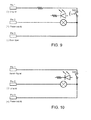
- the printed circuit 24 is designed in to implement the electrical circuits shown in Figures 9 and 10 , which refer to the use of a push-push switch and a momentary pushbutton switch, respectively.
- the electrical circuits shown in Figures 9 and 10 have the same circuit topology, with obvious benefits in terms of reduced area of occupation of the printed circuit 24, which enables the utilization of different types of switches by simply changing the external electrical connection implemented by the external electrical connector that engages, in use, seat 23 of the parabolic body 13, as will be explained below.
- the printed circuit 24 is designed to indifferently allow push-push switches or momentary pushbutton switches to be electrically connected, for example by soldering, at the electrical terminals 27 for the electrical switches 22 for which this option is contemplated.
- Each pair of electrical terminals 27 is constituted by the ends of two electrically conductive tracks, one of which electrically connects the electrical terminal of the corresponding pushbutton switch 22 to a first electrical I/O terminal 25 of the printed circuit 24, indicated in Figures 9 and 10 as "Pin 1", through an optional electrical resistor (which for this reason, is not shown in Figure 10 ) arranged along the electrically conductive track, while the other electrically conductive track electrically connects the electrical terminal of the corresponding pushbutton switch 22 to both a second electrical I/O terminal 25 of the printed circuit 24, indicated in Figures 9 and 10 as "Pin 3", and an electrical terminal of a corresponding electric light source 18 to be switched on/off, whether this be an incandescent electric light source (represented by an unbroken line) or a LED electric light source provided with an associated power supply resistor (represented by an broken line), the other electrical terminal of which is connected, by an electrically conductive track, to a third electrical I/O terminal 25 of the printed circuit 24, indicated in Figures 9 and 10 as "
- the corresponding electric light source 18 is switched on either when any door of the motor vehicle is open, as the electric light source 18 becomes connected between the power supply potential applied to the second electrical terminal Pin2 and the electric ground potential applied to the third electrical terminal Pin3, or when push-push switch 22 is pressed, as the electric light source 18 becomes connected between the power supply potential applied to the second electrical terminal Pin2 and the electric ground potential applied to the first electrical terminal Pin1.
- Figure 10 shows how the external electrical connections are made for the three electrical terminals Pin1, Pin2 and Pin3 of the printed circuit 24 when a momentary pushbutton switch is used.
- the printed circuit 24 is designed to provide, at the location of each electrical switch 22 that can be chosen as a backlit or non-backlit switch, two power supply terminals 27 to which it is possible to electrically connect, for example by soldering or crimping, corresponding electrical terminals of an electric backlight source, conveniently of the LED type, or, when necessary, multiple backlight power sources connected to each other in series, and which are constituted by the ends of two electrically conductive tracks connected to the electrical I/O terminals 25 of the printed circuit 24, so that they can be respectively polarized at a (positive) power supply potential and an electric ground potential.
- an electrical resistor in parallel with the backlight power source(s) is also required, while the provision and electrical connection of the electrical resistors necessary for correct polarization of the backlight power sources is performed using the technique previously described regarding reconfiguration of the overhead light assembly 1 as in a).
- connection of an electrical resistor in parallel with the backlight power source(s) can be performed by making an interrupted electrically conductive track connected in parallel to the electrical terminals to which the backlight power sources will be connected and the electrical continuity of which can be re-established by the connection of the electrical resistor the moment when the backlight power source(s) is/are connected to the associated electrical terminals for backlighting the electrical switch 22.
Landscapes
- Engineering & Computer Science (AREA)
- Mechanical Engineering (AREA)
- Arrangements Of Lighting Devices For Vehicle Interiors, Mounting And Supporting Thereof, Circuits Therefore (AREA)
- Vehicle Interior And Exterior Ornaments, Soundproofing, And Insulation (AREA)
- Non-Portable Lighting Devices Or Systems Thereof (AREA)
Description
- The present invention relates to automotive interior lighting in general and, in particular, to an automotive reconfigurable interior front overhead light assembly.
- As is known, the continuous development of new models of motor vehicles in the automotive sector brings with it the inevitable redesign of countless motor vehicle components dictated by new technical/styling requirements demanded by the market.
- With regard to automotive overhead light assemblies, their redesign is dictated by considerations that are sometimes of an essentially decorative nature, while other times they are of a technical nature and, in general, concern the consumption of electrical resources, safety and overall performance in terms of lighting.
- Considerations of a technical nature generally result in using electric light sources and control elements for switching the electric light sources on and off of one type rather than another, for example, leading to using LED rather than incandescent electric light sources, or control elements that are backlit or otherwise and constituted by rocker switches rather than pushbutton switches, by traditional pushbutton switches, so-called push-push switches, rather than momentary or latching pushbutton switches, and so on.
-
US 2004/264205 A1 discloses a method for installing a modular light assembly in a vehicle, wherein a common printed circuit board base is first provided, one of a plurality of different types of illumination sources is then attached onto the printed circuit board base to form a modular light assembly, and the modular light assembly is then mounted onto one of a plurality of trim bezels. - For evident economic reasons, the applicant became aware of the need to identify solutions aimed at increasing the level of standardization and possibilities of reconfiguration according to the requirements of the automotive overhead light assemblies in order to reduce production costs.
- The object of the present invention is therefore providing an automotive reconfigurable interior overhead light assembly.
- According to the present invention, an automotive reconfigurable interior overhead light assembly is provided, as defined in the appended claims.
-
-
Figures 1 and 2 show perspective views, from above and below, of an automotive reconfigurable overhead light assembly according to the present invention; -
Figures 3 and 4 show exploded views, from above and below, of the overhead light assembly inFigures 1 and 2 ; -
Figures 5, 6 and 7 show perspective views of a printed circuit, along with details thereof, forming part of the overhead light assembly inFigure 1 ; -
Figure 8 shows a perspective view of a possible embodiment of a portion of the printed circuit inFigures 5-7 ; and -
Figures 9 and 10 show wiring diagrams implemented by the printed circuit inFigures 5-7 . - The present invention will now be described in detail with reference to the attached figures to allow an expert in the field to embody it and use it. Various modifications to the described embodiments will be immediately obvious to experts in the field, and the generic principles described herein can be applied to other embodiments and applications without departing from the scope of the present invention, as defined in the appended claims. Thus, the present invention should not be considered as limited to the embodiments set forth herein, but is to be accorded the widest scope consistent with the principles and features disclosed and claimed herein.
- An automotive reconfigurable interior overhead light assembly according to the present invention, in particular a front overhead light assembly, namely located in the front area of the motor vehicle interior to light the driver's seat and front passenger seat, is shown in
Figures 1-4 , where it is indicted as a whole byreference numeral 1. - As shown in these figures, the
overhead light assembly 1 is housed in a removable manner inside a corresponding seat made in roof of the motor vehicle interior and essentially comprises: - a
escutcheon 2 conveniently made of a PC-ABS alloy and defined by a perforated plate, of generally rectangular shaped in the example shown, having acentral portion 3 recessed with respect to its external border 4 to define aseat 5, this also generally rectangular in shape, for a transparent cover panel for the openings, and in which three openings are provided, two lateral 7 ones for the electric light sources and a central 6 one for the electrical switches controlling the electric light sources. In addition, theescutcheon 2 integrally comprises amicrophone cover grille 8 projecting into thecentral opening 6, andperimeter connection interfaces 9 obtained on aperimeter collar 10 projecting from the opposite face of theescutcheon 2 from that on which theseat 5 is provided and conveniently constituted by elastic connecting tabs suitable for snap-engaging matching seats made in the seat of the overhead light assembly in the roof of the motor vehicle interior; - a
transparent cover panel 11 conveniently made of polycarbonate and shaped so as to snap-fit into theseat 5 in theescutcheon 2 and close the three opening 6 and 7 by means of fastening connections suitable for engaging matching seats made in the raised border 4 of theescutcheon 2 externally delimiting theseat 5; - a
chromed ring 12 conveniently made of ABS, having a shape corresponding to that of thecentral opening 6 in theescutcheon 2 and housed in it, by snap fitting, so as to project from the surface of the recessedcentral portion 3 of theescutcheon 2; - a
parabolic body 13 conveniently made of polypropylene and generally rectangular in shape, which is shaped to couple with thecollar 10 of theescutcheon 2 in a removable manner via opportune perimeter connection interfaces conveniently constituted by coupling teeth suitable for engaging matching openings made in thecollar 10. Theparabolic body 13 is shaped so as to define acentral cavity 14 and twolateral cavities 15, arranged in alignment with and facing thecentral opening 6 andlateral openings 7 of theescutcheon 2, respectively, wherein thelateral cavities 15 are provided withcentral openings 16, of circular shape in the example shown, shaped such that they can be engaged by respectiveelectric light sources 18, for example of the LED or incandescent type, suitable for lighting the driver's seat and front passenger seat, respectively, and commonly known by the term "courtesy lights". Theparabolic body 13 also integrally defines awall 19 with a generally U-like shape projecting into thecentral cavity 14 so as to define a pass-throughinner seat 20, of a generally rectangular shape in the example shown, arranged in alignment with themicrophone cover grille 8 of theescutcheon 2 and shaped so as to house a snap-fitted microphone (not shown), and anouter seat 21, of a generally U-like shape in the example shown, provided with threeopenings 17, of a rectangular shape in the example shown, arranged to align with, and shaped so that they can be engaged by, threeelectrical switches 22 for controlling theelectric light sources 18 and fitted with covers conveniently made of a PC-ABS alloy, with backlit ideograms conveniently made of polyoxymethylene, two of which, the lateral ones in the example shown, are pushbutton switches intended for switching theelectric light sources 18 on and off, while the third, the central one in the example shown, is a rocker switch for enabling and disabling the switching on of a central courtesy light when the doors of the motor vehicle are opened. Finally, theparabolic body 13 is shaped so as to integrally define anelectrical connection seat 23 of theoverhead light assembly 1 suitable for being engaged, in use, by an external electrical connector (not shown) through which theoverhead light assembly 1 is connected, in use, to an automotive electrical system; and - a printed
circuit 24, an unsupported printed circuit in the example shown (see alsoFigures 5-7 ), which is carried directly by theparabolic body 13, on the opposite side of the latter with respect to theescutcheon 2, and is constituted by electrically conductive tracks made from punched metal, conveniently FeP01, which are made integral with one another in an opportune manner, via bridges in the example shown, so as to form a single assembly and are made so as to define, among other things, electrical I/O terminals 25 of the printedcircuit 24 arranged inseat 23 of theparabolic body 13 that, in use, will be engaged by an external electrical connector,electrical terminals 26 to electrically connect the twoelectric light sources 18,electrical terminals 27 to electrically connect theelectrical switches 22, an electrical circuit to connect theelectrical switches 22 and theelectric light sources 18 to each other and to the electrical I/O terminals 25 of the printedcircuit 24, as well as electrical terminals to connect printedcircuits 28 equipped withLEDs 29 for backlighting theelectrical switches 22 of anight panel 30 via specially provide prismatic light guides conveniently made of polycarbonate. - According to variants that are not shown, the
overhead light assembly 1 could be made in a version with a so-called baby view mirror, namely fitted with a mirror oriented to allow the driver and front passenger to keep an eye on the rear seats, or in a so-called sunroof version, namely one fitted with additional control buttons for opening and closing a sunroof. - According to the present invention, the printed
circuit 24 is designed to allow reconfiguration of theoverhead light assembly 1 in terms of: - a) interchangeability of the
electric light sources 18, to allow indifferent usage of different types of electric light sources that, due to their nature or operating mode, require different circuit topologies for their power supply, in particular electric light sources of the incandescent type, conveniently halogen lamps, or of the LED type; and - b) interchangeability of
electrical switches 22 to allow indifferent usage ofelectrical switches 22 provided with covers with or without backlightable ideograms and, independently of this, different types ofelectrical switches 22 that, due to their nature or operating mode, require different circuit topologies to switch theelectric light sources 18 on and off, in particular push-push switches or momentary pushbutton switches. - Furthermore, with reference to reconfiguration as in b), conveniently the printed
circuit 24 is further designed to allow reconfiguration of theoverhead light assembly 1 also in terms of: - c) backlighting of the
electrical switches 22, whenelectrical switches 22 fitted with covers having backlightable ideograms are used in theoverhead light assembly 1. - To allow reconfiguration of the
overhead light assembly 1 as in a), the printedcircuit 24 is designed to allow indifferently either lamp holders for incandescent lamps, conveniently halogen lamps, or printed circuits on which LEDs are mounted to be electrically connected atelectrical terminals 26 for theelectric light sources 18. - Furthermore, given that the power supply of a LED-type electric light source requires the presence of an electrical resistor connected in series with the electric light source, an electrical break is made along one of the two electrically conductive tracks provided for powering each of the
electric light sources 18 that splits the electrically conductive track into two electrically isolated segments, the electrical continuity of which can be re-established by means of an electrically conductive connecting element that can be mounted on the printedcircuit 24 to electrically bridge the ends of the two segments of the interrupted electrically conductive track and which can be chosen from either an electrical resistor of opportune electrical resistance for powering a LED, when a LED is used as anelectric light source 18, or a piece of electric conductor of substantially null electrical resistance with respect to that of the electrical resistor, so as to create a short circuit, when an incandescent lamp is used as anelectric light source 18. - Different techniques can be employed for stably retaining this connection element in position.
- One of these techniques could be, for example, that described in
US 2007/0259576 A1 , according to which, as shown inFigure 8 , the ends of the two segments of the electrically conductive track that are electrically separated by the break are snipped in such a way as to form two pairs of facing tabs, which are bent out from the electrically conductive track so as to form two connectors suitable for receiving and stably retaining in a removable manner the corresponding end portions of the piece of electric conductor or leads of the electrical resistor. - Another of these techniques could be that of providing, at each electrical break of the electrically conductive tracks, an associated seat in the
parabolic body 13 shaped to receive and stably retain the electrically conductive element in a removable manner, such that the end portions of the piece of electric conductor or leads of the electrical resistor make electrical contact with the ends of the two electrically isolated segments of the electrically conductive track. In this regard, each seat must therefore be equipped with appropriate means of retaining the connection element, conveniently constituted by coupling teeth. - Instead, to allow reconfiguration of the
overhead light assembly 1 as in b), the printedcircuit 24 is designed in to implement the electrical circuits shown inFigures 9 and 10 , which refer to the use of a push-push switch and a momentary pushbutton switch, respectively. As may be noted, the electrical circuits shown inFigures 9 and 10 have the same circuit topology, with obvious benefits in terms of reduced area of occupation of the printedcircuit 24, which enables the utilization of different types of switches by simply changing the external electrical connection implemented by the external electrical connector that engages, in use,seat 23 of theparabolic body 13, as will be explained below. - In detail, the printed
circuit 24 is designed to indifferently allow push-push switches or momentary pushbutton switches to be electrically connected, for example by soldering, at theelectrical terminals 27 for theelectrical switches 22 for which this option is contemplated. - Each pair of
electrical terminals 27 is constituted by the ends of two electrically conductive tracks, one of which electrically connects the electrical terminal of thecorresponding pushbutton switch 22 to a first electrical I/O terminal 25 of the printedcircuit 24, indicated inFigures 9 and 10 as "Pin 1", through an optional electrical resistor (which for this reason, is not shown inFigure 10 ) arranged along the electrically conductive track, while the other electrically conductive track electrically connects the electrical terminal of thecorresponding pushbutton switch 22 to both a second electrical I/O terminal 25 of the printedcircuit 24, indicated inFigures 9 and 10 as "Pin 3", and an electrical terminal of a correspondingelectric light source 18 to be switched on/off, whether this be an incandescent electric light source (represented by an unbroken line) or a LED electric light source provided with an associated power supply resistor (represented by an broken line), the other electrical terminal of which is connected, by an electrically conductive track, to a third electrical I/O terminal 25 of the printedcircuit 24, indicated inFigures 9 and 10 as "Pin 2". - Depending on how the external electrical connections are made for the three electrical terminals Pin1, Pin2 and Pin3 of the printed
circuit 24, the same circuit topology shown inFigures 9 and 10 enables the use of either a push-push switch or a momentary pushbutton switch. - In particular, as shown in
Figure 9 , when a push-push switch is used, all threeelectrical terminals Pin 1, Pin2 and Pin3 are used as electrical input terminals, in which the first electrical terminal Pin1 is electrically connected to an electric ground potential, the second electrical terminal Pin2 is electrically connected to a (positive) power supply potential and the third electrical terminal Pin3 is electrically connected to all the switches associated with, and operated by, the doors of the motor vehicle, which are in turn connected to an electric ground potential. The door switches are open when the corresponding doors are closed and are closed when the corresponding doors are open, thus resulting in the third electrical terminal Pin3 being floating when all the doors are closed and being connected to an electric ground potential when any one of the doors is opened. - In this way, the corresponding
electric light source 18 is switched on either when any door of the motor vehicle is open, as theelectric light source 18 becomes connected between the power supply potential applied to the second electrical terminal Pin2 and the electric ground potential applied to the third electrical terminal Pin3, or when push-push switch 22 is pressed, as theelectric light source 18 becomes connected between the power supply potential applied to the second electrical terminal Pin2 and the electric ground potential applied to the first electrical terminal Pin1. - Instead,
Figure 10 shows how the external electrical connections are made for the three electrical terminals Pin1, Pin2 and Pin3 of the printedcircuit 24 when a momentary pushbutton switch is used. - Finally, to allow reconfiguration of the
overhead light assembly 1 as in c), the printedcircuit 24 is designed to provide, at the location of eachelectrical switch 22 that can be chosen as a backlit or non-backlit switch, twopower supply terminals 27 to which it is possible to electrically connect, for example by soldering or crimping, corresponding electrical terminals of an electric backlight source, conveniently of the LED type, or, when necessary, multiple backlight power sources connected to each other in series, and which are constituted by the ends of two electrically conductive tracks connected to the electrical I/O terminals 25 of the printedcircuit 24, so that they can be respectively polarized at a (positive) power supply potential and an electric ground potential. - If the backlighting of an
electrical switch 22 is performed by one or more backlight power sources of the LED type, in addition to providing an electrical resistor in series with the backlight power source(s), an electrical resistor in parallel with the backlight power source(s) is also required, while the provision and electrical connection of the electrical resistors necessary for correct polarization of the backlight power sources is performed using the technique previously described regarding reconfiguration of theoverhead light assembly 1 as in a). In particular, the connection of an electrical resistor in parallel with the backlight power source(s) can be performed by making an interrupted electrically conductive track connected in parallel to the electrical terminals to which the backlight power sources will be connected and the electrical continuity of which can be re-established by the connection of the electrical resistor the moment when the backlight power source(s) is/are connected to the associated electrical terminals for backlighting theelectrical switch 22.
Claims (7)
- An automotive reconfigurable interior overhead light assembly (1) comprising:• a support body (2, 13) fastenable in a seat made in an interior roof of a motor vehicle;• a printed circuit (24) carried by the support body (2, 13) and comprising electrically conductive tracks formed to define electrical I/O terminals (25) of the printed circuit (24) engageable by an external electrical connector, electrical terminals (26) to electrically connect at least one electric light source (18), electrical terminals (27) to electrically connect at least one electrical switch (22), and an electrical circuit to connect the electrical switch (22) and the electric light source (18) to each other and to the electrical I/O terminals (25) of the printed circuit (24);• at least one electric light source (18) electrically connected to the corresponding electrical terminals (26) of the printed circuit (24) for lighting an area of the motor vehicle interior; and• at least one electrical switch (22) electrically connected to the corresponding electrical terminals (26) of the printed circuit (24) to control the electric light source (18);
wherein the printed circuit (24) is designed to allow:a) interchangeability of the electric light source (18), so as to allow indifferent usage of different types of electric light sources that, due to their nature or operating mode, require different circuit topologies for their power supply; andb) interchangeability of the electrical switch (22) so as to allow indifferent usage of different types of electrical switches (22) that, due to their nature or operating mode, require different circuit topologies to switch the electric light source (18) on and off;
characterized in that the printed circuit (24) is further designed to allow:c) backlighting of an electrical switch (22), when an electrical switch (22) fitted with a cover having a backlightable ideogram is used in the overhead light assembly (1);wherein, as to allow reconfiguration as in c), the printed circuit (24) is designed to form, at each location of an electrical switch (22) that can be chosen as a backlit or non-backlit switch, two power supply terminals (27) connected to the electrical I/O terminals (25) of the printed circuit (24) and to which corresponding electrical terminals of an electric backlight source may be electrically connected. - An automotive reconfigurable interior overhead light assembly (1) according to claim 1, wherein, as to allow reconfiguration as in a), the printed circuit (24) is designed to provide, along one of the two electrically conductive tracks supplying power to the electric light source (18), an electrical break that splits the electrically conductive track into two electrically isolated segments, the electrical continuity of which can be re-established by means of an electrically conductive connecting element that can be mounted on the printed circuit (24) to electrically bridge the ends of the two segments of the interrupted electrically conductive track and which can be chosen from different electrical components required for supplying power to the different types of electric light source.
- An automotive reconfigurable interior overhead light assembly (1) according to claim 2, wherein the printed circuit (24) is designed to allow indifferently either an incandescent electric light source or a LED electric light source to be electrically connected to the electrical terminals (26) for the electric light source (18); and wherein the electrical component can be chosen from either an electrical resistor necessary for supplying power to a LED electric light source or a piece of electric conductor suitable to make a short circuit for supplying power to an incandescent electric light source.
- An automotive reconfigurable interior overhead light assembly (1) according to claim 3, wherein the ends of the two segments of the electrically conductive track that are electrically separated by the break form two pairs of facing, bent out tabs of the electrically conductive track so as to form two connectors adapted to receive and stably retain in a removable manner corresponding end portions of the piece of electric conductor or leads of the electrical component.
- An automotive reconfigurable interior overhead light assembly (1) according to claim 3, wherein the support body (2, 13) defines, at the electrical break of the electrically conductive track, an associated seat so shaped as to receive and stably retain in a removable manner the electrically conductive connecting element, so that end portions of the piece of electrical conductor or leads of the electrical component come into electric contact with the ends of the two electrically isolated segments of the electrically conductive track.
- An automotive reconfigurable interior overhead light assembly (1) according to any of the preceding claims, wherein, as to allow reconfiguration as in b), in which the printed circuit (24) is designed to form an electrical circuit having a circuit topology such that using different electrical switches (22) only requires changing the external electrical connection of the electrical I/O terminals (25) of the printed circuit (24).
- An automotive reconfigurable interior overhead light assembly (1) according to claim 6, wherein the printed circuit (24) is designed to allow indifferently either a push-push switch or a momentary pushbutton switch to be electrically connected to the electrical terminals (27) for the electrical switch (22);
wherein the printed circuit (24) is designed to form an electrical circuit wherein one of the two electrical terminals (27) for the electrical switch (22) is electrically connected to a first (Pin 1) electrical I/O terminal (25) of the printed circuit (24) and the other of the two electrical terminals (27) for the electrical switch (22) is electrically connected both to a second (Pin 2) electrical I/O terminal (25) of the printed circuit (24) and to one of the two electrical terminals (26) for the electric light source (18) to be controlled, while the other of the two electrical terminals (26) for the electric light source (18) is electrically connected to a third (Pin 3) electrical I/O terminal (25) of the printed circuit (24);
wherein, if a push-push switch is used, the first (Pin 1) electrical I/O terminal (25) of the printed circuit (24) is intended to be electrically connected to an electric ground potential, the second (Pin 2) electrical I/O terminal (25) of the printed circuit (24) is intended to be electrically connected to an power supply potential and the third (Pin 3) electrical I/O terminal (25) of the printed circuit (24) is intended to be electrically connected to switches associated with, and operated by, motor vehicle doors, which are in turn connected to an electric ground potential, so as to result in the third (Pin 3) electrical I/O terminal (25) of the printed circuit (24) being floating when all the doors are closed and being connected to an electric ground potential when any one of the doors is opened, whereby the electric light source (18) is turned on either when any one of the doors is opened or when the push-push switch (22) is operated;
and wherein, if a momentary pushbutton switch is used, the first (Pin 1) electrical I/O terminal (25) of the printed circuit (24) is intended to receive an input signal, the second (Pin 2) electrical I/O terminal (25) of the printed circuit (24) is intended to be electrically connected to an electric ground potential, and the third (Pin 3) electrical I/O terminal (25) of the printed circuit (24) is intended to be electrically connected to a power supply potential.
Applications Claiming Priority (1)
| Application Number | Priority Date | Filing Date | Title |
|---|---|---|---|
| IT000965A ITTO20120965A1 (en) | 2012-11-05 | 2012-11-05 | AUTROYCOLISTIC RECONFIGURABLE CEILING LIGHT |
Publications (2)
| Publication Number | Publication Date |
|---|---|
| EP2727770A1 EP2727770A1 (en) | 2014-05-07 |
| EP2727770B1 true EP2727770B1 (en) | 2015-07-29 |
Family
ID=47471951
Family Applications (1)
| Application Number | Title | Priority Date | Filing Date |
|---|---|---|---|
| EP13191698.3A Active EP2727770B1 (en) | 2012-11-05 | 2013-11-05 | Automotive reconfigurable overhead light assembly |
Country Status (2)
| Country | Link |
|---|---|
| EP (1) | EP2727770B1 (en) |
| IT (1) | ITTO20120965A1 (en) |
Families Citing this family (1)
| Publication number | Priority date | Publication date | Assignee | Title |
|---|---|---|---|---|
| US10101018B2 (en) | 2015-09-22 | 2018-10-16 | Ford Global Technologies, Llc | Dome light assembly with integral removable lamp unit for use in emergencies |
Family Cites Families (11)
| Publication number | Priority date | Publication date | Assignee | Title |
|---|---|---|---|---|
| US6124886A (en) * | 1997-08-25 | 2000-09-26 | Donnelly Corporation | Modular rearview mirror assembly |
| JP3877192B2 (en) * | 1997-10-24 | 2007-02-07 | 第一電装部品株式会社 | Vehicle interior light |
| JP3977004B2 (en) * | 2000-10-13 | 2007-09-19 | 株式会社小糸製作所 | Interior lighting |
| DE10202955B4 (en) * | 2002-01-26 | 2004-02-05 | Apag Elektronik Ag | Interior light for a motor vehicle |
| US7128450B2 (en) * | 2003-06-27 | 2006-10-31 | Lear Corporation | Modular light assembly and method for installing a modular light assembly in a vehicle |
| JP4494052B2 (en) * | 2004-03-19 | 2010-06-30 | 矢崎総業株式会社 | Interior lighting |
| US20070259576A1 (en) * | 2006-05-03 | 2007-11-08 | Brandt Bruce B | Metal carrier for LEDs in composite lamps |
| WO2008024985A2 (en) * | 2006-08-25 | 2008-02-28 | Johnson Controls Technology Company | Integrated power source for interior led lighting |
| US8020270B2 (en) * | 2008-02-05 | 2011-09-20 | Putco, Inc. | Apparatus for replacing a dome light in a fixture |
| US20100177530A1 (en) * | 2009-01-13 | 2010-07-15 | Ford Global Technologies, Llc | Vehicle headliner module |
| DE202009012306U1 (en) * | 2009-09-11 | 2009-12-17 | Johnson Controls Technology Company, Holland | Replaceable light module |
-
2012
- 2012-11-05 IT IT000965A patent/ITTO20120965A1/en unknown
-
2013
- 2013-11-05 EP EP13191698.3A patent/EP2727770B1/en active Active
Also Published As
| Publication number | Publication date |
|---|---|
| EP2727770A1 (en) | 2014-05-07 |
| ITTO20120965A1 (en) | 2014-05-06 |
Similar Documents
| Publication | Publication Date | Title |
|---|---|---|
| US7537256B2 (en) | Component module applique for vehicle lift gate | |
| CN100472688C (en) | Combination operation switch assembly | |
| US9328891B1 (en) | Vehicle lamp unit | |
| US7108309B2 (en) | Sun visor with conducting arm for vehicles | |
| US5756949A (en) | Unit structure for hazard switch | |
| US20130092519A1 (en) | Rotary switch | |
| CN100480100C (en) | Bus bar substrate for vehicle interior light | |
| KR101601512B1 (en) | Multifunctional integration module for mounting in the rear of vehicle | |
| CN201652096U (en) | Vehicle ceiling module | |
| EP2727770B1 (en) | Automotive reconfigurable overhead light assembly | |
| US20120184150A1 (en) | Electric cable holder and method for connecting the same | |
| KR20190052976A (en) | Call buzzer switch for bus | |
| EP1232542B1 (en) | Dual function lamp socket | |
| US9045083B2 (en) | Integrated release switch assembly | |
| KR101211311B1 (en) | Multi-function switch assembly of vehicles and mounting method of the sames | |
| US20030168881A1 (en) | Lock control assembly for a motor vehicle opening panel and opening panel equipped with same | |
| JP2007030768A (en) | Insulation structure between bus bars for vehicle interior lights | |
| JP4738928B2 (en) | Thermal insulation structure for vehicle interior lights | |
| CN202624049U (en) | Wireless light-emitting pedal for vehicle | |
| CN202196670U (en) | Light-modulating fog lamp switch | |
| WO2004037607A3 (en) | Switching arrangement for actuating lighting systems on a motor vehicle | |
| CN219115251U (en) | An integrated door and window controller | |
| CN222235098U (en) | Car light controller and car light control system | |
| CN101515517B (en) | Switching device | |
| JP3151738B2 (en) | Vehicle lighting |
Legal Events
| Date | Code | Title | Description |
|---|---|---|---|
| PUAI | Public reference made under article 153(3) epc to a published international application that has entered the european phase |
Free format text: ORIGINAL CODE: 0009012 |
|
| 17P | Request for examination filed |
Effective date: 20131105 |
|
| AK | Designated contracting states |
Kind code of ref document: A1 Designated state(s): AL AT BE BG CH CY CZ DE DK EE ES FI FR GB GR HR HU IE IS IT LI LT LU LV MC MK MT NL NO PL PT RO RS SE SI SK SM TR |
|
| AX | Request for extension of the european patent |
Extension state: BA ME |
|
| 17P | Request for examination filed |
Effective date: 20141106 |
|
| RBV | Designated contracting states (corrected) |
Designated state(s): AL AT BE BG CH CY CZ DE DK EE ES FI FR GB GR HR HU IE IS IT LI LT LU LV MC MK MT NL NO PL PT RO RS SE SI SK SM TR |
|
| RIC1 | Information provided on ipc code assigned before grant |
Ipc: B60Q 3/02 20060101AFI20150109BHEP |
|
| GRAP | Despatch of communication of intention to grant a patent |
Free format text: ORIGINAL CODE: EPIDOSNIGR1 |
|
| INTG | Intention to grant announced |
Effective date: 20150220 |
|
| GRAS | Grant fee paid |
Free format text: ORIGINAL CODE: EPIDOSNIGR3 |
|
| GRAA | (expected) grant |
Free format text: ORIGINAL CODE: 0009210 |
|
| AK | Designated contracting states |
Kind code of ref document: B1 Designated state(s): AL AT BE BG CH CY CZ DE DK EE ES FI FR GB GR HR HU IE IS IT LI LT LU LV MC MK MT NL NO PL PT RO RS SE SI SK SM TR |
|
| REG | Reference to a national code |
Ref country code: GB Ref legal event code: FG4D |
|
| REG | Reference to a national code |
Ref country code: CH Ref legal event code: EP |
|
| REG | Reference to a national code |
Ref country code: AT Ref legal event code: REF Ref document number: 738981 Country of ref document: AT Kind code of ref document: T Effective date: 20150815 |
|
| REG | Reference to a national code |
Ref country code: IE Ref legal event code: FG4D |
|
| REG | Reference to a national code |
Ref country code: DE Ref legal event code: R096 Ref document number: 602013002442 Country of ref document: DE |
|
| REG | Reference to a national code |
Ref country code: DE Ref legal event code: R082 Ref document number: 602013002442 Country of ref document: DE Representative=s name: ANDREJEWSKI - HONKE PATENT- UND RECHTSANWAELTE, DE |
|
| REG | Reference to a national code |
Ref country code: FR Ref legal event code: PLFP Year of fee payment: 3 |
|
| REG | Reference to a national code |
Ref country code: AT Ref legal event code: MK05 Ref document number: 738981 Country of ref document: AT Kind code of ref document: T Effective date: 20150729 |
|
| REG | Reference to a national code |
Ref country code: LT Ref legal event code: MG4D |
|
| REG | Reference to a national code |
Ref country code: NL Ref legal event code: MP Effective date: 20150729 |
|
| PG25 | Lapsed in a contracting state [announced via postgrant information from national office to epo] |
Ref country code: FI Free format text: LAPSE BECAUSE OF FAILURE TO SUBMIT A TRANSLATION OF THE DESCRIPTION OR TO PAY THE FEE WITHIN THE PRESCRIBED TIME-LIMIT Effective date: 20150729 Ref country code: LT Free format text: LAPSE BECAUSE OF FAILURE TO SUBMIT A TRANSLATION OF THE DESCRIPTION OR TO PAY THE FEE WITHIN THE PRESCRIBED TIME-LIMIT Effective date: 20150729 Ref country code: GR Free format text: LAPSE BECAUSE OF FAILURE TO SUBMIT A TRANSLATION OF THE DESCRIPTION OR TO PAY THE FEE WITHIN THE PRESCRIBED TIME-LIMIT Effective date: 20151030 Ref country code: NO Free format text: LAPSE BECAUSE OF FAILURE TO SUBMIT A TRANSLATION OF THE DESCRIPTION OR TO PAY THE FEE WITHIN THE PRESCRIBED TIME-LIMIT Effective date: 20151029 Ref country code: LV Free format text: LAPSE BECAUSE OF FAILURE TO SUBMIT A TRANSLATION OF THE DESCRIPTION OR TO PAY THE FEE WITHIN THE PRESCRIBED TIME-LIMIT Effective date: 20150729 |
|
| PG25 | Lapsed in a contracting state [announced via postgrant information from national office to epo] |
Ref country code: SE Free format text: LAPSE BECAUSE OF FAILURE TO SUBMIT A TRANSLATION OF THE DESCRIPTION OR TO PAY THE FEE WITHIN THE PRESCRIBED TIME-LIMIT Effective date: 20150729 Ref country code: PL Free format text: LAPSE BECAUSE OF FAILURE TO SUBMIT A TRANSLATION OF THE DESCRIPTION OR TO PAY THE FEE WITHIN THE PRESCRIBED TIME-LIMIT Effective date: 20150729 Ref country code: ES Free format text: LAPSE BECAUSE OF FAILURE TO SUBMIT A TRANSLATION OF THE DESCRIPTION OR TO PAY THE FEE WITHIN THE PRESCRIBED TIME-LIMIT Effective date: 20150729 Ref country code: RS Free format text: LAPSE BECAUSE OF FAILURE TO SUBMIT A TRANSLATION OF THE DESCRIPTION OR TO PAY THE FEE WITHIN THE PRESCRIBED TIME-LIMIT Effective date: 20150729 Ref country code: AT Free format text: LAPSE BECAUSE OF FAILURE TO SUBMIT A TRANSLATION OF THE DESCRIPTION OR TO PAY THE FEE WITHIN THE PRESCRIBED TIME-LIMIT Effective date: 20150729 Ref country code: IS Free format text: LAPSE BECAUSE OF FAILURE TO SUBMIT A TRANSLATION OF THE DESCRIPTION OR TO PAY THE FEE WITHIN THE PRESCRIBED TIME-LIMIT Effective date: 20151129 Ref country code: PT Free format text: LAPSE BECAUSE OF FAILURE TO SUBMIT A TRANSLATION OF THE DESCRIPTION OR TO PAY THE FEE WITHIN THE PRESCRIBED TIME-LIMIT Effective date: 20151130 Ref country code: HR Free format text: LAPSE BECAUSE OF FAILURE TO SUBMIT A TRANSLATION OF THE DESCRIPTION OR TO PAY THE FEE WITHIN THE PRESCRIBED TIME-LIMIT Effective date: 20150729 |
|
| PG25 | Lapsed in a contracting state [announced via postgrant information from national office to epo] |
Ref country code: NL Free format text: LAPSE BECAUSE OF FAILURE TO SUBMIT A TRANSLATION OF THE DESCRIPTION OR TO PAY THE FEE WITHIN THE PRESCRIBED TIME-LIMIT Effective date: 20150729 |
|
| PG25 | Lapsed in a contracting state [announced via postgrant information from national office to epo] |
Ref country code: EE Free format text: LAPSE BECAUSE OF FAILURE TO SUBMIT A TRANSLATION OF THE DESCRIPTION OR TO PAY THE FEE WITHIN THE PRESCRIBED TIME-LIMIT Effective date: 20150729 Ref country code: DK Free format text: LAPSE BECAUSE OF FAILURE TO SUBMIT A TRANSLATION OF THE DESCRIPTION OR TO PAY THE FEE WITHIN THE PRESCRIBED TIME-LIMIT Effective date: 20150729 Ref country code: SK Free format text: LAPSE BECAUSE OF FAILURE TO SUBMIT A TRANSLATION OF THE DESCRIPTION OR TO PAY THE FEE WITHIN THE PRESCRIBED TIME-LIMIT Effective date: 20150729 Ref country code: CZ Free format text: LAPSE BECAUSE OF FAILURE TO SUBMIT A TRANSLATION OF THE DESCRIPTION OR TO PAY THE FEE WITHIN THE PRESCRIBED TIME-LIMIT Effective date: 20150729 |
|
| REG | Reference to a national code |
Ref country code: DE Ref legal event code: R097 Ref document number: 602013002442 Country of ref document: DE |
|
| PG25 | Lapsed in a contracting state [announced via postgrant information from national office to epo] |
Ref country code: RO Free format text: LAPSE BECAUSE OF FAILURE TO SUBMIT A TRANSLATION OF THE DESCRIPTION OR TO PAY THE FEE WITHIN THE PRESCRIBED TIME-LIMIT Effective date: 20150729 |
|
| PLBE | No opposition filed within time limit |
Free format text: ORIGINAL CODE: 0009261 |
|
| STAA | Information on the status of an ep patent application or granted ep patent |
Free format text: STATUS: NO OPPOSITION FILED WITHIN TIME LIMIT |
|
| PG25 | Lapsed in a contracting state [announced via postgrant information from national office to epo] |
Ref country code: LU Free format text: LAPSE BECAUSE OF FAILURE TO SUBMIT A TRANSLATION OF THE DESCRIPTION OR TO PAY THE FEE WITHIN THE PRESCRIBED TIME-LIMIT Effective date: 20151105 Ref country code: MC Free format text: LAPSE BECAUSE OF FAILURE TO SUBMIT A TRANSLATION OF THE DESCRIPTION OR TO PAY THE FEE WITHIN THE PRESCRIBED TIME-LIMIT Effective date: 20150729 |
|
| 26N | No opposition filed |
Effective date: 20160502 |
|
| REG | Reference to a national code |
Ref country code: IE Ref legal event code: MM4A |
|
| PG25 | Lapsed in a contracting state [announced via postgrant information from national office to epo] |
Ref country code: SI Free format text: LAPSE BECAUSE OF FAILURE TO SUBMIT A TRANSLATION OF THE DESCRIPTION OR TO PAY THE FEE WITHIN THE PRESCRIBED TIME-LIMIT Effective date: 20150729 |
|
| PG25 | Lapsed in a contracting state [announced via postgrant information from national office to epo] |
Ref country code: IE Free format text: LAPSE BECAUSE OF NON-PAYMENT OF DUE FEES Effective date: 20151105 |
|
| REG | Reference to a national code |
Ref country code: DE Ref legal event code: R079 Ref document number: 602013002442 Country of ref document: DE Free format text: PREVIOUS MAIN CLASS: B60Q0003020000 Ipc: B60Q0003200000 Ref country code: FR Ref legal event code: PLFP Year of fee payment: 4 |
|
| PG25 | Lapsed in a contracting state [announced via postgrant information from national office to epo] |
Ref country code: BE Free format text: LAPSE BECAUSE OF FAILURE TO SUBMIT A TRANSLATION OF THE DESCRIPTION OR TO PAY THE FEE WITHIN THE PRESCRIBED TIME-LIMIT Effective date: 20150729 |
|
| PG25 | Lapsed in a contracting state [announced via postgrant information from national office to epo] |
Ref country code: HU Free format text: LAPSE BECAUSE OF FAILURE TO SUBMIT A TRANSLATION OF THE DESCRIPTION OR TO PAY THE FEE WITHIN THE PRESCRIBED TIME-LIMIT; INVALID AB INITIO Effective date: 20131105 Ref country code: BG Free format text: LAPSE BECAUSE OF FAILURE TO SUBMIT A TRANSLATION OF THE DESCRIPTION OR TO PAY THE FEE WITHIN THE PRESCRIBED TIME-LIMIT Effective date: 20150729 |
|
| PG25 | Lapsed in a contracting state [announced via postgrant information from national office to epo] |
Ref country code: CY Free format text: LAPSE BECAUSE OF FAILURE TO SUBMIT A TRANSLATION OF THE DESCRIPTION OR TO PAY THE FEE WITHIN THE PRESCRIBED TIME-LIMIT Effective date: 20150729 |
|
| REG | Reference to a national code |
Ref country code: CH Ref legal event code: PL |
|
| PG25 | Lapsed in a contracting state [announced via postgrant information from national office to epo] |
Ref country code: CH Free format text: LAPSE BECAUSE OF NON-PAYMENT OF DUE FEES Effective date: 20161130 Ref country code: LI Free format text: LAPSE BECAUSE OF NON-PAYMENT OF DUE FEES Effective date: 20161130 |
|
| PG25 | Lapsed in a contracting state [announced via postgrant information from national office to epo] |
Ref country code: MT Free format text: LAPSE BECAUSE OF FAILURE TO SUBMIT A TRANSLATION OF THE DESCRIPTION OR TO PAY THE FEE WITHIN THE PRESCRIBED TIME-LIMIT Effective date: 20150729 |
|
| REG | Reference to a national code |
Ref country code: FR Ref legal event code: PLFP Year of fee payment: 5 |
|
| PG25 | Lapsed in a contracting state [announced via postgrant information from national office to epo] |
Ref country code: SM Free format text: LAPSE BECAUSE OF FAILURE TO SUBMIT A TRANSLATION OF THE DESCRIPTION OR TO PAY THE FEE WITHIN THE PRESCRIBED TIME-LIMIT Effective date: 20150729 |
|
| PG25 | Lapsed in a contracting state [announced via postgrant information from national office to epo] |
Ref country code: MK Free format text: LAPSE BECAUSE OF FAILURE TO SUBMIT A TRANSLATION OF THE DESCRIPTION OR TO PAY THE FEE WITHIN THE PRESCRIBED TIME-LIMIT Effective date: 20150729 |
|
| GBPC | Gb: european patent ceased through non-payment of renewal fee |
Effective date: 20171105 |
|
| PG25 | Lapsed in a contracting state [announced via postgrant information from national office to epo] |
Ref country code: AL Free format text: LAPSE BECAUSE OF FAILURE TO SUBMIT A TRANSLATION OF THE DESCRIPTION OR TO PAY THE FEE WITHIN THE PRESCRIBED TIME-LIMIT Effective date: 20150729 Ref country code: TR Free format text: LAPSE BECAUSE OF FAILURE TO SUBMIT A TRANSLATION OF THE DESCRIPTION OR TO PAY THE FEE WITHIN THE PRESCRIBED TIME-LIMIT Effective date: 20150729 |
|
| PG25 | Lapsed in a contracting state [announced via postgrant information from national office to epo] |
Ref country code: GB Free format text: LAPSE BECAUSE OF NON-PAYMENT OF DUE FEES Effective date: 20171105 |
|
| PGFP | Annual fee paid to national office [announced via postgrant information from national office to epo] |
Ref country code: DE Payment date: 20241022 Year of fee payment: 12 |
|
| PGFP | Annual fee paid to national office [announced via postgrant information from national office to epo] |
Ref country code: FR Payment date: 20241022 Year of fee payment: 12 |
|
| PGFP | Annual fee paid to national office [announced via postgrant information from national office to epo] |
Ref country code: IT Payment date: 20241022 Year of fee payment: 12 |