EP2727728A1 - Viscous material feeder - Google Patents
Viscous material feeder Download PDFInfo
- Publication number
- EP2727728A1 EP2727728A1 EP20130001886 EP13001886A EP2727728A1 EP 2727728 A1 EP2727728 A1 EP 2727728A1 EP 20130001886 EP20130001886 EP 20130001886 EP 13001886 A EP13001886 A EP 13001886A EP 2727728 A1 EP2727728 A1 EP 2727728A1
- Authority
- EP
- European Patent Office
- Prior art keywords
- viscous material
- nozzle
- feed route
- solder
- passage portion
- Prior art date
- Legal status (The legal status is an assumption and is not a legal conclusion. Google has not performed a legal analysis and makes no representation as to the accuracy of the status listed.)
- Granted
Links
Images




Classifications
-
- B—PERFORMING OPERATIONS; TRANSPORTING
- B41—PRINTING; LINING MACHINES; TYPEWRITERS; STAMPS
- B41J—TYPEWRITERS; SELECTIVE PRINTING MECHANISMS, i.e. MECHANISMS PRINTING OTHERWISE THAN FROM A FORME; CORRECTION OF TYPOGRAPHICAL ERRORS
- B41J2/00—Typewriters or selective printing mechanisms characterised by the printing or marking process for which they are designed
- B41J2/005—Typewriters or selective printing mechanisms characterised by the printing or marking process for which they are designed characterised by bringing liquid or particles selectively into contact with a printing material
- B41J2/01—Ink jet
-
- B—PERFORMING OPERATIONS; TRANSPORTING
- B23—MACHINE TOOLS; METAL-WORKING NOT OTHERWISE PROVIDED FOR
- B23K—SOLDERING OR UNSOLDERING; WELDING; CLADDING OR PLATING BY SOLDERING OR WELDING; CUTTING BY APPLYING HEAT LOCALLY, e.g. FLAME CUTTING; WORKING BY LASER BEAM
- B23K3/00—Tools, devices or special appurtenances for soldering, e.g. brazing, or unsoldering, not specially adapted for particular methods
- B23K3/06—Solder feeding devices; Solder melting pans
- B23K3/0607—Solder feeding devices
- B23K3/0638—Solder feeding devices for viscous material feeding, e.g. solder paste feeding
-
- B—PERFORMING OPERATIONS; TRANSPORTING
- B41—PRINTING; LINING MACHINES; TYPEWRITERS; STAMPS
- B41F—PRINTING MACHINES OR PRESSES
- B41F15/00—Screen printers
- B41F15/14—Details
- B41F15/40—Inking units
-
- B—PERFORMING OPERATIONS; TRANSPORTING
- B41—PRINTING; LINING MACHINES; TYPEWRITERS; STAMPS
- B41F—PRINTING MACHINES OR PRESSES
- B41F17/00—Printing apparatus or machines of special types or for particular purposes, not otherwise provided for
-
- B—PERFORMING OPERATIONS; TRANSPORTING
- B41—PRINTING; LINING MACHINES; TYPEWRITERS; STAMPS
- B41J—TYPEWRITERS; SELECTIVE PRINTING MECHANISMS, i.e. MECHANISMS PRINTING OTHERWISE THAN FROM A FORME; CORRECTION OF TYPOGRAPHICAL ERRORS
- B41J2/00—Typewriters or selective printing mechanisms characterised by the printing or marking process for which they are designed
- B41J2/005—Typewriters or selective printing mechanisms characterised by the printing or marking process for which they are designed characterised by bringing liquid or particles selectively into contact with a printing material
- B41J2/01—Ink jet
- B41J2/17—Ink jet characterised by ink handling
- B41J2/175—Ink supply systems ; Circuit parts therefor
-
- H—ELECTRICITY
- H05—ELECTRIC TECHNIQUES NOT OTHERWISE PROVIDED FOR
- H05K—PRINTED CIRCUITS; CASINGS OR CONSTRUCTIONAL DETAILS OF ELECTRIC APPARATUS; MANUFACTURE OF ASSEMBLAGES OF ELECTRICAL COMPONENTS
- H05K3/00—Apparatus or processes for manufacturing printed circuits
- H05K3/10—Apparatus or processes for manufacturing printed circuits in which conductive material is applied to the insulating support in such a manner as to form the desired conductive pattern
- H05K3/12—Apparatus or processes for manufacturing printed circuits in which conductive material is applied to the insulating support in such a manner as to form the desired conductive pattern using thick film techniques, e.g. printing techniques to apply the conductive material or similar techniques for applying conductive paste or ink patterns
- H05K3/1216—Apparatus or processes for manufacturing printed circuits in which conductive material is applied to the insulating support in such a manner as to form the desired conductive pattern using thick film techniques, e.g. printing techniques to apply the conductive material or similar techniques for applying conductive paste or ink patterns by screen printing or stencil printing
- H05K3/1233—Methods or means for supplying the conductive material and for forcing it through the screen or stencil
-
- H—ELECTRICITY
- H05—ELECTRIC TECHNIQUES NOT OTHERWISE PROVIDED FOR
- H05K—PRINTED CIRCUITS; CASINGS OR CONSTRUCTIONAL DETAILS OF ELECTRIC APPARATUS; MANUFACTURE OF ASSEMBLAGES OF ELECTRICAL COMPONENTS
- H05K2203/00—Indexing scheme relating to apparatus or processes for manufacturing printed circuits covered by H05K3/00
- H05K2203/01—Tools for processing; Objects used during processing
- H05K2203/0104—Tools for processing; Objects used during processing for patterning or coating
- H05K2203/0126—Dispenser, e.g. for solder paste, for supplying conductive paste for screen printing or for filling holes
-
- H—ELECTRICITY
- H05—ELECTRIC TECHNIQUES NOT OTHERWISE PROVIDED FOR
- H05K—PRINTED CIRCUITS; CASINGS OR CONSTRUCTIONAL DETAILS OF ELECTRIC APPARATUS; MANUFACTURE OF ASSEMBLAGES OF ELECTRICAL COMPONENTS
- H05K3/00—Apparatus or processes for manufacturing printed circuits
- H05K3/30—Assembling printed circuits with electric components, e.g. with resistors
- H05K3/32—Assembling printed circuits with electric components, e.g. with resistors electrically connecting electric components or wires to printed circuits
- H05K3/34—Assembling printed circuits with electric components, e.g. with resistors electrically connecting electric components or wires to printed circuits by soldering
- H05K3/3465—Application of solder
- H05K3/3485—Application of solder paste, slurry or powder
Definitions
- a viscous material feeder including a nozzle to discharge a viscous material is known in general.
- Such a viscous material feeder is disclosed in Japanese Patent Laying-Open No. 2010-179628 , for example.
- Japanese Patent Laying-open no. 2010-179628 discloses a solder printer including a solder feeder feeding solder (viscous material) onto a surface of a mask and a squeegee scraping off the solder fed onto the surface of the mask.
- the solder feeder of this solder printer includes a container storing the solder, a discharge adapter attached to an opening of the container, a feed mechanism to feed the solder from the container, a guide block formed with a solder flow path, and a feed port discharging the solder at a tip of the guide block.
- the solder flow path of the guide block is formed to extend obliquely, and the solder flow path in the feed port at the tip of the guide block is formed to extend vertically.
- the solder feeder according to Japanese Patent Laying-open no. 2010-179628 has a bent feed route to feed the solder by the guide block and the feed port.
- the centerline of the exit portion 50b is located a distance D1 away from a centerline (coinciding with the central axis line of the discharge adapter 45) passing through the entrance portion 50a to the squeegee 32 (in the direction Y2). Therefore, a distance D3 in the direction Y between the exit portion 50b and the squeegee 32 (support shaft 31a) is smaller than a distance D2 in the direction Y between the entrance portion 50a and the squeegee 32, as shown in Fig. 2 .
- the nozzle 43 is arranged to be oblique in a horizontal plane (X-Y plane), and Fig. 5 is an oblique sectional view taken along a boundary surface (61, 71), described later, of the obliquely arranged nozzle 43.
- the exit passage portion 53 extends linearly along the discharging direction (vertical direction) of the solder discharged from the exit portion 50b.
- the inclined passage portion 52 and the exit passage portion 53 are connected by a bent portion 55 formed in a smoothly curved shape (R-shape).
- the bent portion 54, the inclined passage portion 52, and the bent portion 55 have a constant flow path width (flow path inner diameter).
- the exit passage portion 53 is formed with a narrow portion 53a whose flow path width (flow path inner diameter) on the side of the exit portion 50b is narrowed.
- the narrow portion 53a has a function of inhibiting the solder remaining in the feed route 50 after discharge from dropping (dripping) from the exit portion 50b.
- the nozzle 43 is configured to be dividable along the bent feed route 50, as shown in Figs. 6 and 7 .
- the feed route 50 constituted by the aforementioned flow path portions is so formed that a central axis line CA (see Fig. 8 ) passing through the feed route 50 leading from the entrance portion 50a to the exit portion 50b at the tip is arranged in a single plane, and the nozzle 43 is configured to be dividable in half along the feed route 50, using this plane as the boundary surface (61, 71).
- the boundary surfaces 61 and 71 are examples of the "plane" in the present invention.
Landscapes
- Engineering & Computer Science (AREA)
- Mechanical Engineering (AREA)
- Manufacturing & Machinery (AREA)
- Microelectronics & Electronic Packaging (AREA)
- Electric Connection Of Electric Components To Printed Circuits (AREA)
- Screen Printers (AREA)
Abstract
Description
- The priority application number
JP2012-236881 - The present invention relates to a viscous material feeder, and more particularly, it relates to a viscous material feeder including a nozzle to discharge a viscous material.
- A viscous material feeder including a nozzle to discharge a viscous material is known in general. Such a viscous material feeder is disclosed in Japanese Patent Laying-Open No.
2010-179628 - Japanese Patent Laying-open no.
2010-179628 2010-179628 - In the solder feeder, the solder, which is a viscous material, is likely to remain in the feed route and hardens with time, and hence it is necessary to clean the feed route during maintenance. However, the solder feeder according to Japanese Patent Laying-open no.
2010-179628 2010-179628 - The present invention has been proposed in order to solve the aforementioned problem, and an object of the present invention is to provide a viscous material feeder capable of inhibiting a viscous material from remaining in a feed route by improving cleaning workability in the feed route during maintenance.
- In order to attain the aforementioned object, a viscous material feeder according to an aspect of the present invention includes a nozzle to discharge a viscous material stored in a storage portion storing the viscous material and a feeding mechanism transferring the viscous material from the storage portion to the nozzle and discharging the viscous material from the nozzle, while the nozzle has a bent feed route to guide the viscous material from the storage portion to a tip of the nozzle and is configured to be dividable along the bent feed route.
- As hereinabove described, the viscous material feeder according to the aspect of the present invention is provided with the nozzle having the bent feed route to guide the viscous material from the storage portion to the tip of the nozzle and configured to be dividable along the bent feed route, whereby during maintenance, the feed route can be cleaned in a state where the nozzle is divided along the bent feed route to expose the feed route. Thus, even the feed route having a bent portion can be easily cleaned, and hence cleaning workability in the feed route during maintenance can be improved, and the cleaning state of the feed route can be checked to inhibit the viscous material from remaining in the feed route.
- In the aforementioned viscous material feeder according to the aspect, the bent portion of the bent feed route of the nozzle is preferably formed in a smoothly curved shape. According to this structure, even in the structure of providing the bent feed route in the nozzle, the bent portion is not bent sharply so that increase in viscous material flow resistance in viscous material feeding can be suppressed. Consequently, even in the structure of providing the bent feed route in the nozzle, increase in a load on the feeding mechanism discharging the viscous material (power necessary to feed the viscous material) can be suppressed. Furthermore, the bent portion is not bent sharply, and hence a corner portion thereof can be easily cleaned. Thus, cleaning workability can be improved.
- In this case, the feed route of the nozzle preferably includes a straight passage portion formed in a linear manner and continuing from an entrance portion, and the straight passage portion preferably extends along the feeding direction of the viscous material fed from the storage portion to the entrance portion. According to this structure, in the straight passage portion, the feeding direction of the viscous material fed from the entrance portion is not changed, and hence the viscous material can be smoothly injected into the entrance portion (a connection portion between the nozzle and an external portion).
- In the aforementioned structure having the feed route including the straight passage portion, the straight passage portion preferably has such a shape that an end portion thereof closer to the entrance portion widens toward the entrance portion. According to this structure, the feed route widens at the entrance portion (the connection portion between the nozzle and the external portion), and hence the viscous material can be more smoothly injected into the entrance portion.
- In the aforementioned structure having the feed route including the straight passage portion, the feed route of the nozzle preferably further includes an inclined passage portion connected to the straight passage portion and inclined with respect to the straight passage portion, and the inclined passage portion preferably linearly extends obliquely downward from a portion connecting to the straight passage portion toward an exit portion. According to this structure, as compared with a case where an arcuate inclined passage portion is provided, for example, a feed path of the viscous material to the exit portion can be reduced, and hence increase in viscous material flow resistance with increase in the feed path length of the viscous material can be suppressed.
- In this case, the straight passage portion and the inclined passage portion are preferably connected by the bent portion formed in the smoothly curved shape. According to this structure, increase in viscous material flow resistance in a connection portion between the straight passage portion and the inclined passage portion can be suppressed.
- In the aforementioned structure having the feed route including the inclined passage portion, the feed route of the nozzle preferably further includes an exit passage portion extending linearly along the discharging direction of the viscous material discharged from the exit portion, and the inclined passage portion and the exit passage portion are preferably connected by the bent portion formed in the smoothly curved shape. According to this structure, increase in viscous material flow resistance in a connection portion between the inclined passage portion and the exit passage portion can be suppressed. Furthermore, the flow direction of the viscous material can be aligned with the discharging direction of the viscous material from the exit portion in the exit passage portion, and hence the viscous material can be smoothly discharged from the exit portion.
- In the aforementioned viscous material feeder according to the aspect, the nozzle preferably includes a first member and a second member divided along the feed route and a fixing member arranged outside the first member or the second member to attach the divided first and second members to each other. According to this structure, the feed route can be divided into two parts, and hence cleaning workability in the feed route can be improved. Furthermore, the fixing member is provided separately from the first member and the second member, whereby the first member and the second member formed with the feed route can be simplified in structure, and hence cleaning workability in the first member and the second member including the feed route can be improved.
- In this case, each of the first member and the second member preferably has through-holes into which screw members are inserted, and the fixing member is preferably formed with screw holes into which the screw members passing through the through-holes of each of the first member and the second member are screwed. According to this structure, the first member and the second member are fastened together using the screw members and the fixing member, whereby the first member and the second member can be fixed to each other. Furthermore, in a case where the first member and the second member provided with the feed route are formed with the screw holes, the viscous material remaining in the feed route may partially enter the screw holes in cleaning. In this case, it is not easy to remove the viscous material entering the screw holes from the screw holes, and the screw members may be damaged by the viscous material when the viscous material such as solder hardens. In contrast, according to the present invention, the first member and the second member are formed with the through-holes, and the fixing member is formed with the screw holes. Thus, the first member and the second member provided with the feed route may be simply formed with the through-holes not the screw holes, and hence the viscous material remaining in the feed route can be prevented from partially entering the screw holes in cleaning. Consequently, cleaning workability can be improved.
- In the aforementioned structure having the fixing member formed with the screw holes, a plurality of screw holes of the fixing member are preferably so formed in pairs that the screw members are arranged on both sides to sandwich the feed route therebetween. According to this structure, both sides of the feed route can be evenly fastened by pairs of screw members. Therefore, in the structure of dividing the feed route into the first member and the second member, the boundary of the feed route can be tightly fastened by a minimum necessary number of screw members.
- In the aforementioned structure having the nozzle including the first member, the second member, and the fixing member, the first member preferably has a flat outer surface, and the fixing member preferably has a flat plate shape and is preferably configured to come into surface contact with the flat outer surface of the first member. According to this structure, the first member and the fixing member are brought into close contact (surface contact) with each other, whereby the first member and the second member can be strongly fixed to the fixing member. Furthermore, the fixing member is in the form of a simple flat plate, whereby assembly and disassembly of the nozzle associated with cleaning can be facilitated.
- In the aforementioned structure having the nozzle including the first member, the second member, and the fixing member, the first member and the second member preferably have flat surface portions arranged in the same plane in a state where the first member and the second member are attached to each other, respectively, and the nozzle is preferably so configured that the mutual positions of the first member and the second member are determined in a state where the flat surface portions of the first member and the second member are brought into contact with a flat reference surface when the divided first and second members are attached to each other by the fixing member. According to this structure, the first member and the second member can be easily positioned with a simple structure requiring no positioning member (such as a positioning pin) separately, for example by bringing the flat surface portions into contact with the reference surface when the first member and the second member are attached to each other.
- In the aforementioned viscous material feeder according to the aspect, the bent feed route is preferably so formed that a central axis line passing through the feed route leading from an entrance portion to an exit portion at the tip is arranged in a single plane, and the nozzle is preferably configured to be dividable in half along the feed route, using the plane as a boundary. According to this structure, the entire feed route can be divided in half, and hence the feed route can be easily cleaned. The boundary surface of the divided nozzle is plat, and hence the nozzle can be easily formed with high accuracy as compared with a case where the nozzle is so divided that the boundary surface is curved, for example.
- The aforementioned viscous material feeder according to the aspect may further include a discharge adapter including a flow path causing an inner portion of the storage portion storing the viscous material and the feed route of the nozzle to communicate with each other, and the feeding mechanism may be configured to relatively move the discharge adapter and the storage portion to transfer the viscous material stored in the storage portion to the nozzle configured to be dividable through the discharge adapter.
- In the aforementioned viscous material feeder according to the aspect, the viscous material preferably includes a cream solder, a conductive paste, and an adhesive for temporarily attaching a chip. According to this structure, in the viscous material feeder feeding the viscous material such as the cream solder, the conductive paste, and the adhesive for temporarily attaching a chip employed to manufacture an electronic circuit board, cleaning workability in the feed route can be improved, and the viscous material can be inhibited from remaining in the feed route.
- The foregoing and other objects, features, aspects and advantages of the present invention will become more apparent from the following detailed description of the present invention when taken in conjunction with the accompanying drawings.
-
-
Fig. 1 is a perspective view schematically showing the overall structure of a printer according to an embodiment of the present invention; -
Fig. 2 is a side elevational view schematically showing the overall structure of the printer according to the embodiment of the present invention; -
Fig. 3 is a front elevational view showing a solder feed portion of the printer according to the embodiment of the present invention; -
Fig. 4 is a side elevational view of the solder feed portion shown inFig. 3 ; -
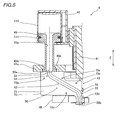
Fig. 5 is a sectional view schematically showing the solder feed portion shown inFig. 3 taken along a boundary surface of a nozzle; -
Fig. 6 is a perspective view showing the nozzle of the solder feed portion according to the embodiment of the present invention; -
Fig. 7 is an exploded perspective view of the nozzle shown inFig. 6 ; -
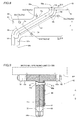
Fig. 8 illustrates a portion on the boundary surface between a first member and a second member of the nozzle shown inFig. 6 ; -
Fig. 9 is a sectional view of the nozzle taken along the line 500-500 inFig. 8 ; and -
Figs. 10A to 10F illustrate the outline of a printing operation of the printer according to the embodiment of the present invention. - An embodiment of the present invention is now described with reference to the drawings.
- First, the structure of a
printer 100 according to the embodiment of the present invention is described with reference toFigs. 1 to 9 . In this embodiment, the viscous material is a viscous material employed to manufacture an electronic circuit board, and more specifically, the viscous material includes a cream solder (solder), a conductive paste (silver paste or the like, for example), an adhesive for temporarily attaching a chip, etc. In this embodiment, the solder is employed as an example of the viscous material. - The
printer 100 according to this embodiment has a function of printing the solder onto a surface of a printed board 200 (hereinafter referred to as a "board 200") with amask 300 formed with a plurality of openings in a prescribed pattern. Theprinter 100 includes abase 1, aboard conveying portion 2 provided on thebase 1 and conveying theboard 200, asqueegee unit 3 provided above theboard conveying portion 2, and asolder feed portion 4 above theboard conveying portion 2, as shown inFig. 1 . Thesolder feed portion 4 is an example of the "viscous material feeder" in the present invention. - The
board conveying portion 2 includes a pair of carrying-inconveyors 5a carrying theboard 200 before printing in theprinter 100 and a pair of carrying-outconveyors 5b carrying theboard 200 after printing out of theprinter 100, as shown inFig. 1 . Theboard conveying portion 2 is provided between the carrying-inconveyors 5a and the carrying-outconveyors 5b and includes a conveyingsupport mechanism 20 conveying (delivering) and supporting the board. - The conveying
support mechanism 20 includes amovable plate 21 having a rectangular shape in a plan view, a pair ofconveyors 22 provided on themovable plate 21, a backup unit 23 (seeFig. 2 ), and aclamping mechanism 24. The conveyingsupport mechanism 20 is configured to support theboard 200 in a state where the conveyedboard 200 is moved to a prescribed printing position and is positioned with respect to themask 300. - Specifically, the
movable plate 21 is movably supported by amovement mechanism 21a, and themovement mechanism 21a is configured to be movable along orthogonal three axes (an X-axis, a Y-axis, and a Z-axis) and to be movable about a vertical axis (Z-axis), as shown inFigs. 1 and2 . Thus, themovable plate 21 is configured to be movable in a conveying direction (direction X) of theboard 200, an anteroposterior direction (direction Y) (seeFig. 2 ) orthogonal to the conveying direction, and a vertical direction (direction Z) and to be rotatable along a rotation direction about the vertical axis. - The pair of
conveyors 22 have a function of receiving theboard 200 before printing from the carrying-inconveyors 5a and conveying theboard 200 after printing to the carrying-outconveyors 5b. - The
backup unit 23 is placed on themovable plate 21 and is so configured that abackup plate 23a thereof is vertically movable by an unshown lifting drive portion, as shown inFig. 2 . Thebackup unit 23 has a function of lifting theboard 200 conveyed by the pair ofconveyors 22 from theconveyors 22 with a plurality of unshown backup pins attached to thebackup plate 23a and moving theboard 200 upward to the prescribed printing position. Theboard 200 moved upward to the prescribed printing position is clamped by theclamping mechanism 24. Thus, theboard 200 is supported at the prescribed printing position below themask 300. - As shown in
Fig. 1 , themask 300 is formed with the plurality of openings in the prescribed pattern corresponding to application regions of the solder applied to theboard 200. Themask 300 has a rectangular shape in a plan view and has aframe 301 mounted on the outer periphery thereof. Theframe 301 is clamped bymask clamp portions 6, whereby themask 300 is fixedly held above the conveyingsupport mechanism 20. - The
squeegee unit 3 is arranged above themask 300. Thesqueegee unit 3 has a function of scraping and spreading the solder fed onto the upper surface of themask 300 over the upper surface of themask 300 by reciprocating in the anteroposterior direction (direction Y). Thus, the solder is printed (transferred) onto the surface of theboard 200 through the openings of themask 300. Specifically, thesqueegee unit 3 includes ahead 31 and asqueegee 32 mounted on a lower portion of thehead 31, as shown inFigs. 1 and2 . - The
squeegee unit 3 is supported to be movable in the anteroposterior direction (direction Y) by a pair of rails 7 (seeFig. 1 ). Thesqueegee unit 3 is provided with a Y-axis drive motor 33 moving thehead 31 in the anteroposterior direction (direction Y). - The
head 31 includes alifting mechanism 34 moving thesqueegee 32 vertically and asqueegee rotation mechanism 35 rotating thesqueegee 32 using asupport shaft 31a as a rotation center. Thesqueegee 32 is mounted on thehead 31 to be rotatable using thesupport shaft 31a extending in the direction X as a rotation center, as shown inFig. 2 . - The
squeegee 32 is formed to extend in the direction X and has a scraping surface (operating surface) 32a to scrape off the solder. Thesqueegee 32 is so configured that thescraping surface 32a slides in the anteroposterior direction (direction Y) on the upper surface of themask 300 to scrape off the solder on the upper surface of themask 300. Thesqueegee 32 is rotated about thesupport shaft 31a by thesqueegee rotation mechanism 35 to reverse the direction of thescraping surface 32a with respect to themask 300, whereby advancing printing (printing in a direction Y1 from the back forward) and returning printing (printing in a direction Y2 from before backward) can be performed. - The
solder feed portion 4 has a function of feeding the solder printed (transferred) onto theboard 200 through themask 300 onto themask 300. Thesolder feed portion 4 is arranged on the front side (Y1 direction side) of thesqueegee unit 3 and is mounted on the front side of thehead 31 in a state of being movable in the direction X by a feedportion movement mechanism 4a, as shown inFig. 1 . Therefore, thesolder feed portion 4 is configured to move in the direction Y integrally with the squeegee unit 3 (squeegee 32) and to be movable in the direction X independently of the squeegee unit 3 (squeegee 32). Thesolder feed portion 4 can feed the solder while moving along the extensional direction X of thesqueegee 32. - As shown in
Figs. 3 to 5 , thesolder feed portion 4 mainly includes asupport plate 41, a soldercontainer holding portion 42 holding asolder container 110 in which the solder is stored, anozzle 43 to discharge the solder stored in thesolder container 110, and afeeding mechanism 44 transferring the solder from thesolder container 110 to thenozzle 43 and discharging the solder from thenozzle 43. Thesupport plate 41 is supported by thehead 31 through the feedportion movement mechanism 4a. - The solder
container holding portion 42 is mounted on thesupport plate 41 in a state of being movable vertically. The soldercontainer holding portion 42 is configured to detachably hold thesolder container 110 to which adischarge adapter 45 is attached. - As the
solder container 110, a commercially available container distributed in a state of storing a solder paste can be employed. This commerciallyavailable solder container 110 has a cylindrical shape including a bottom portion closed at one end and anopening 111 opened at another end, as shown inFig. 5 , for example. Thedischarge adapter 45 has an outer shape corresponding to the inner shape of thesolder container 110 and is configured to be fittable into thesolder container 110 from the side of theopening 111. Thedischarge adapter 45 is tightly attached to (fitted into) thesolder container 110 in a state of being slidable along the inner surface of the container. Thedischarge adapter 45 is formed with aflow path 45a penetrating vertically in a central portion. Theflow path 45a is configured to cause the inner portion of thesolder container 110 and afeed route 50, described later, of thenozzle 43 to communicate with each other. Thedischarge adapter 45 and thesolder container 110 are so relatively moved that thedischarge adapter 45 is inserted into thesolder container 110, whereby the solder stored in thesolder container 110 is pushed out to thedischarge adapter 45 and is discharged through theflow path 45a. Thesolder container 110 is an example of the "storage portion" in the present invention. - As shown in
Figs. 3 and 4 , thefeeding mechanism 44 is mounted on thesupport plate 41 and is configured to lift the soldercontainer holding portion 42 vertically. Thefeeding mechanism 44 moves (relatively moves) thesolder container 110 down to thedischarge adapter 45 through the soldercontainer holding portion 42, whereby the solder stored in thesolder container 110 is transferred from theflow path 45a of thedischarge adapter 45 to thenozzle 43 and is discharged from thenozzle 43 to themask 300. Thisfeeding mechanism 44 is constituted by a screw feed mechanism including a ball nut (not shown) and a ball screw shaft (not shown) connected to the soldercontainer holding portion 42 and a drive motor (not shown) driving the ball screw shaft to lift the ball nut, a rack-and-pinion mechanism (not shown), or the like, for example. - The
nozzle 43 has thebent feed route 50 to guide the solder from thesolder container 110 to a tip of thenozzle 43, as shown inFig. 5 . Specifically, thenozzle 43 is so configured that the horizontal position of anexit portion 50b of thefeed route 50 is away from the horizontal position of anentrance portion 50a of thefeed route 50, as shown inFigs. 5 to 8 . As shown inFigs. 2 and4 , thenozzle 43 is so mounted on thesupport plate 41 that theexit portion 50b is closer to thesqueegee 32 of thesqueegee unit 3 than theentrance portion 50a (seeFig. 5 ). In other words, the centerline of theexit portion 50b is located a distance D1 away from a centerline (coinciding with the central axis line of the discharge adapter 45) passing through theentrance portion 50a to the squeegee 32 (in the direction Y2). Therefore, a distance D3 in the direction Y between theexit portion 50b and the squeegee 32 (support shaft 31a) is smaller than a distance D2 in the direction Y between theentrance portion 50a and thesqueegee 32, as shown inFig. 2 . As shown inFigs. 3 and 4 , thenozzle 43 is arranged to be oblique in a horizontal plane (X-Y plane), andFig. 5 is an oblique sectional view taken along a boundary surface (61, 71), described later, of the obliquely arrangednozzle 43. - As shown in
Fig. 8 , thefeed route 50 includes a straightentrance passage portion 51 continuing from theentrance portion 50a, aninclined passage portion 52 connected to theentrance passage portion 51 and inclined with respect to theentrance passage portion 51, and a straightexit passage portion 53 connecting to theexit portion 50b. The cross-sectional surface of thefeed route 50 orthogonal to a flow direction is circularly formed. As shown inFig. 5 , theentrance portion 50a of thisfeed route 50 is connected to an exit-side end portion of theflow path 45a of thedischarge adapter 45, and thefeed route 50 of thenozzle 43 is communicated with the inner portion (the storage area of the solder) of thesolder container 110 through theflow path 45a of thedischarge adapter 45. Theentrance passage portion 51 is an example of the "straight passage portion" in the present invention. - As shown in
Figs. 5 and8 , theentrance passage portion 51 extends linearly along the feeding direction (vertical direction) of the solder fed from thesolder container 110 to theentrance portion 50a. Theentrance passage portion 51 has such a shape that an end portion (upper end portion) closer to theentrance portion 50a widens toward theentrance portion 50a (upward). Theinclined passage portion 52 linearly extends obliquely downward from a portion (bent portion 54) connecting to theentrance passage portion 51 toward theexit portion 50b. Theentrance passage portion 51 and theinclined passage portion 52 are connected by thebent portion 54 formed in a smoothly curved shape (R-shape). - The
exit passage portion 53 extends linearly along the discharging direction (vertical direction) of the solder discharged from theexit portion 50b. Theinclined passage portion 52 and theexit passage portion 53 are connected by abent portion 55 formed in a smoothly curved shape (R-shape). Thebent portion 54, theinclined passage portion 52, and thebent portion 55 have a constant flow path width (flow path inner diameter). On the other hand, theexit passage portion 53 is formed with anarrow portion 53a whose flow path width (flow path inner diameter) on the side of theexit portion 50b is narrowed. Thenarrow portion 53a has a function of inhibiting the solder remaining in thefeed route 50 after discharge from dropping (dripping) from theexit portion 50b. - According to this embodiment, the
nozzle 43 is configured to be dividable along thebent feed route 50, as shown inFigs. 6 and 7 . Specifically, thefeed route 50 constituted by the aforementioned flow path portions is so formed that a central axis line CA (seeFig. 8 ) passing through thefeed route 50 leading from theentrance portion 50a to theexit portion 50b at the tip is arranged in a single plane, and thenozzle 43 is configured to be dividable in half along thefeed route 50, using this plane as the boundary surface (61, 71). The boundary surfaces 61 and 71 are examples of the "plane" in the present invention. - Specifically, the
nozzle 43 includes afirst member 60 and asecond member 70 in which a half of thefeed route 50 divided by the boundary surface (61, 71) is formed, respectively and a fixingmember 80 to attach thefirst member 60 and thesecond member 70 to each other and fix the same. - The
first member 60 has theboundary surface 61 in which a half of thefeed route 50 is formed and aflange portion 62 formed to protrude outward (to a side opposite to the boundary surface 61) on the end portion closer to theentrance portion 50a. Similarly, thesecond member 70 has theboundary surface 71 in which a half of thefeed route 50 is formed and aflange portion 72 formed to protrude outward (to a side opposite to the boundary surface 71) on the end portion closer to theentrance portion 50a. Thefirst member 60 is formed with four through-holes screw members 85 pass, and thesecond member 70 is formed with four through-holes screw members 85 pass. As shown inFig. 9 , the inner diameter of each of these through-holes 63a to 63d and 73a to 73d (Fig. 9 only shows the through-holes screw members 85. The through-holes 63a to 63d and 73a to 73d are formed with no screw (female screw). - The
flange portions nozzle 43 to mountingportions 41a provided on thesupport plate 41, as shown inFigs. 3 and5 . As shown inFigs. 6 and9 , theupper surface 62a of theflange portion 62 and theupper surface 72a of theflange portion 72 are flat surfaces formed to be arranged in the same plane (coplanar) in a state where thefirst member 60 and thesecond member 70 are attached to each other. Thenozzle 43 is so configured that the mutual positions of thefirst member 60 and thesecond member 70 to attach the dividedfirst member 60 andsecond member 70 to each other by the fixingmember 80 are determined in a state where theupper surface 62a of thefirst member 60 and theupper surface 72a of thesecond member 70 are brought into contact with a flat reference surface RP (seeFig. 9 ) such as a surface plate. Theupper surfaces - The fixing
member 80 is arranged outside the first member 60 (on a side opposite to the second member 70), as shown inFig. 7 . The outer surface of thefirst member 60 closer to the fixingmember 80 is flattened, and the fixingportion 80 has a flat plate shape and is formed to come into surface contact with the flat outer surface of thefirst member 60. The fixingmember 80 is formed with fourscrew holes screw hole 81a corresponds to the through-hole 63a of thefirst member 60 and the through-hole 73a of thesecond member 70, thescrew hole 81b corresponds to the through-hole 63b and the through-hole 73b, thescrew hole 81c corresponds to the through-hole 63c and the through-hole 73c, and thescrew hole 81d corresponds to the through-hole 63d and the through-hole 73d. - As shown in
Fig. 9 , thescrew members 85 passing through the through-holes 73a to 73d of thesecond member 70 and the through-holes 63a to 63d of thefirst member 60 are screwed into the fourscrew holes 81a to 81d, respectively. Thus, thescrew members 85 screwed into the screw holes 81a to 81d, respectively and the fixingmember 80 are tightened, whereby thefirst member 60 and thesecond member 70 between thescrew members 85 and the fixingmember 80 are fixed (attached) to each other. - According to this embodiment, a plurality of (two) pairs of
screw holes 81a to 81d of the fixingmember 80 are so formed that thescrew members 85 are arranged on both sides to sandwich thefeed route 50 therebetween, as shown inFig. 8 . In other words, thescrew hole 81a (through-holes screw hole 81b (through-holes feed route 50 therebetween. Thescrew hole 81c (through-holes screw hole 81d (through-holes feed route 50 therebetween. - A distance Dc between the
screw hole 81c (through-holes feed route 50 and a distance Dd between thescrew hole 81d (through-holes feed route 50 are substantially equal to each other. Distances from thescrew members 85 to the central axis line CA of thefeed route 50 are substantially equal to each other on both sides, whereby fastening force can be evenly exerted on both sides of thefeed route 50. The distances from the screw members 85 (screw holes) to the central axis line CA may not be strictly equal to each other. A distance Db between thescrew hole 81b (through-holes feed route 50 is slightly larger than a distance Da between thescrew hole 81a (through-holes feed route 50. - The
nozzle 43 having the aforementioned structure is detachably mounted on the mountingportions 41a of thesupport plate 41 together with thedischarge adapter 45, as shown inFigs. 3 to 5 . Specifically, the mountingportions 41a are arranged (seeFig. 3 ) on both sides to sandwich thedischarge adapter 45 therebetween at the position of thedisparage adapter 45 on the exit side and are formed to vertically engage (seeFig. 5 ) with the upper surface of aflange portion 45b formed on an exit-side end portion of thedischarge adapter 45. A pair ofclamp lever 41b are provided on the lower surface sides of the mountingportions 41a. Theflange portions nozzle 43 and theflange portion 45b of thedischarge adapter 45 on the exit side are vertically held between the lower surfaces of the mountingportions 41a and a clamp portion of theclamp lever 41b, whereby thenozzle 43 and thedischarge adapter 45 are fixed to thesupport plate 41. - A
shutter mechanism 46 fixed to thesupport plate 41 is arranged at a position in the vicinity of theexit portion 50b of thenozzle 43. Thisshutter mechanism 46 is configured to be movable to a position where theexit portion 50b of thenozzle 43 is covered and a position where theexit portion 50b is opened. Theshutter mechanism 46 is opened and closed, whereby the start of solder feeding and the stop of solder feeding are controlled and leakage of the solder can be prevented when the solder is not fed. - Second, maintenance of the
nozzle 43 of thesolder feed portion 4 in theprinter 100 according to this embodiment is described with reference toFigs. 3 ,7 , and9 . - During the maintenance, clamping of the pair of clamp levers 41b (see
Fig. 3 ) of thesolder feed portion 4 is released, whereby thenozzle 43 is detached from thesolder feed portion 4. Thescrew members 85 screwed into the fixingmember 80 are removed, whereby the fixingmember 80 is detached from thenozzle 43. Then, thenozzle 43 is divided into thefirst member 60 and thesecond member 70. Thus, theentire feed route 50 of thenozzle 43 is exposed in a state where thefeed route 50 is divided into two halves, as shown inFig. 7 . At this time, the solder remains in the dividedfeed route 50 in thefirst member 60 and thesecond member 70. An operator removes the solder remaining in the dividedfeed route 50 with a spatula or the like and cleans thefeed route 50 with a waste cloth (cleaning cloth) or the like. At this time, even if the remaining solder enters the through-holes (63a to 63d, 73a to 73d), the screws are not inserted into these through-holes (63a to 63d, 73a to 73d) so that the remaining solder can be easily removed. Furthermore, even if the remaining solder hardens in the through-holes, thescrew members 85 are not damaged in assembling. - After cleaning is finished, the
nozzle 43 is assembled. Thefirst member 60 and thesecond member 70 are turned upside down, and theupper surface 62a of thefirst member 60 and theupper surface 72a of thesecond member 70 are brought into contact with the flat reference surface RP (seeFig. 9 ) such as a surface plate to position thefirst member 60 and thesecond member 70.Fig. 9 shows a state where thefirst member 60 and thesecond member 70 are attached to each other, and thefirst member 60 and thesecond member 70 are not turned upside down inFig. 9 . - The fixing
member 80 is arranged on the outer surface of thefirst member 60, and thescrew members 85 are inserted into the through-holes (63a to 63d, 73a to 73d) from the side of thesecond member 70. Thescrew members 85 passing through the through-holes (63a to 63d, 73a to 73d), respectively, are screwed into the screw holes 81a to 81d of the fixingmember 80 and are fastened, whereby thefirst member 60 and thesecond member 70 are fixed (attached) to each other. Thus, the assembly of thenozzle 43 is completed, and thenozzle 43 is attached to thesolder feed portion 4 to finish the maintenance. - Third, the outline of a printing operation of the
printer 100 according to this embodiment is described with reference toFigs. 1 and10A to 10F . - In the printing operation, the
squeegee 32 is rotated, whereby advancing printing and returning printing are performed. When the carried-inboard 200 is arranged at the printing position on the lower surface side of themask 300 by the conveying support mechanism 20 (seeFig. 1 ), the printing operation is started. - As shown in
Fig. 10A , thesqueegee 32 comes into contact with a puddle of the solder AS formed at a prescribed position on themask 300 from the Y2 direction side, and thesqueegee unit 3 moves in the direction Y1 (forward, in an advancing direction). At this time, thesqueegee 32 slides on the upper surface of themask 300 together with the puddle of the solder AS, whereby the openings of themask 300 are filled up with the solder, and solder printing (advancing printing) is performed on theboard 200. Thesqueegee unit 3 stops at a prescribed position (advancing printing finish position) in the advancing direction where thesqueegee 32 passes through the printing area of themask 300. Thereafter, theboard 200 after printing is carried out of theprinter 100, and theboard 200 before printing is carried in theprinter 100 and is arranged at the printing position. - As shown in
Fig. 10B , the solder is fed to the puddle of the solder AS. When the solder is fed to the puddle of the solder AS, thesqueegee 32 is rotated until thescraping surface 32a of thesqueegee 32 becomes perpendicular to themask 300 in order to avoid interference, thesqueegee unit 3 moves backward (in the direction Y2) to a solder feed position, and theexit portion 50b of thenozzle 43 is arranged over the puddle of the solder AS. Thefeeding mechanism 44 operates to discharge the solder in thesolder container 110 from theexit portion 50b of thenozzle 43. At this time, thesolder feed portion 4 is moved in the direction X by the feedportion movement mechanism 4a (seeFig. 1 ), and the solder is evenly fed over the overall width of the puddle of the solder AS corresponding to the width of thesqueegee 32. When the amount of reduction in the solder resulting from the advancing printing is less than a prescribed amount, feeding of the solder is skipped. - As shown in
Fig. 10C , thesqueegee 32 is positioned at a prescribed returning printing start position. In other words, thesqueegee unit 3 moves forward (in the direction Y1), and thesqueegee 32 is rotated to an angle position for returning printing and comes into contact with the puddle of the solder AS on themask 300 from the Y1 direction side. - When the
squeegee 32 is positioned at the returning printing start position, thesqueegee unit 3 moves in the direction Y2 (backward, in a returning direction), and returning printing is performed, as shown inFig. 10D . Thesqueegee unit 3 stops at a prescribed position (returning printing finish position) in the returning direction where thesqueegee 32 passes through the printing area of themask 300. Thereafter, theboard 200 after printing is carried out of theprinter 100, and theboard 200 before printing is carried in theprinter 100 and is arranged at the printing position. - After the returning printing is finished, the
squeegee unit 3 moves backward (in the direction Y2) to a solder feed position, and the solder is fed to the puddle of the solder AS, as shown inFig. 10E . When the amount of reduction in the solder resulting from the returning printing is less than the prescribed amount, feeding of the solder is skipped. - As shown in
Fig. 10F , thesqueegee 32 is positioned at an advancing printing start position. In other words, thesqueegee 32 is rotated to an angle position for advancing printing and comes into contact with the puddle of the solder AS on themask 300 from the Y2 direction side. Thereafter, the printing operation returns toFig. 10A , and subsequent advancing printing is performed. The aforementioned operations are repeated, whereby the printing operation of theprinter 100 is performed. - According to this embodiment, the
exit portion 50b of thenozzle 43 is arranged closer to thesqueegee 32 by the distance D1 (seeFig. 2 ) than theentrance portion 50a, and hence a movement distance D11 from the advancing printing finish position inFig. 10A to the solder feed position inFig. 10B and a movement distance D12 from the solder feed position inFig. 10B to the returning printing start position inFig. 10C are reduced. Similarly, a movement distance D13 from the returning printing finish position inFig. 10D to the solder feed position inFig. 10E and a movement distance D14 from the solder feed position inFig. 10E to the advancing printing start position inFig. 10F are reduced. - In other words, when the
solder feed portion 4 moves in the direction Y integrally with thesqueegee unit 3, the movement distances D11 to D14 from the advancing (returning) printing finish position to the solder feed position and from the solder feed position to the returning (advancing) printing start position are determined depending on a distance D3 in the direction Y from theexit portion 50b of thenozzle 43 to thesqueegee 32. Therefore, as compared with a case where theexit portion 50b is at the same position in the direction Y as theentrance portion 50a (a distance from theexit portion 50b to thesqueegee 32 is D2 inFig. 2 ), for example, theexit portion 50b of thenozzle 43 is closer to thesqueegee 32 so that a movement distance associated with solder feeding can be reduced according to this embodiment. Thus, the time required for printing can be reduced. - In a case where the distance D3 from the
exit portion 50b to thesqueegee 32 is larger, thesqueegee 32 may be located over the printing area (area where the openings are formed) of themask 300 when the solder is fed after the advancing printing is finished, as shown inFig. 10B . In this case, it is necessary to move the advancing printing finish position inFig. 10A forward (in the direction Y1) in order to prevent the solder adhering to thesqueegee 32 from dropping in the printing area. Therefore, the movement distance of thesqueegee 32 in printing is increased. According to this embodiment, theexit portion 50b of thenozzle 43 is closer to thesqueegee 32, so that the advancing printing finish position inFig. 10A can be brought close to the printing area of themask 300. Thus, the movement distance in printing can be reduced, and the movement range of thesqueegee unit 3 in the direction Y can be reduced. - According to this embodiment, as hereinabove described, the
printer 100 is provided with thenozzle 43 having thebent feed route 50 to guide the solder from thesolder container 110 to the tip of thenozzle 43 and configured to be dividable along thebent feed route 50, whereby during maintenance, thefeed route 50 can be cleaned in the state where thenozzle 43 is divided along thebent feed route 50 to expose thefeed route 50. Thus, even thefeed route 50 having the bent portions (54, 55) can be easily cleaned, and hence cleaning workability in thefeed route 50 during maintenance can be improved, and the cleaning state of thefeed route 50 can be checked to inhibit the solder from remaining in thefeed route 50. According to this embodiment, the bent portions (54, 55) of thebent feed route 50 of thenozzle 43 each are formed in the smoothly curved shape. Thus, even in the structure of providing thebent feed route 50 in thenozzle 43, the bent portions (54, 55) are not bent sharply so that increase in solder flow resistance in solder feeding can be suppressed. Consequently, even in the structure of providing thebent feed route 50 in thenozzle 43, increase in a load on thefeeding mechanism 44 discharging the solder (power necessary to feed the solder) can be suppressed. Furthermore, the bent portions (54, 55) are not bent sharply, and hence corner portions thereof can be easily cleaned. Thus, cleaning workability can be improved. - According to this embodiment, the
entrance passage portion 51 is formed to extend along the feeding direction of the solder fed from thesolder container 110 to the entrance portion. Thus, in theentrance passage portion 51, the solder can be smoothly injected into theentrance portion 50a (a connection portion between thenozzle 43 and the discharge adapter 45). Furthermore, theinclined passage portion 52 is formed to linearly extend obliquely downward from the portion (bent portion 54) connecting to theentrance passage portion 51 toward theexit portion 50b. Thus, as compared with a case where an arcuateinclined passage portion 52 is provided, for example, a feed path of the solder to theexit portion 50b can be reduced, and hence increase in solder flow resistance with increase in feed path length can be suppressed. In addition, theentrance passage portion 51 and theinclined passage portion 52 are connected by thebent portion 54 formed in the smoothly curved shape. Thus, increase in solder flow resistance in a connection portion between theentrance passage portion 51 and theinclined passage portion 52 can be suppressed. - According to this embodiment, the
entrance passage portion 51 is formed in such a shape that the end portion closer to theentrance portion 50a widens toward theentrance portion 50a (upward). Thus, thefeed route 50 widens at theentrance portion 50a (the connection portion between thenozzle 43 and the discharge adapter 45), and hence the solder can be more smoothly injected into theentrance portion 50a. - According to this embodiment, the
feed route 50 of thenozzle 43 is provided with theexit passage portion 53 extending linearly along the discharging direction (vertical direction) of the solder discharged from theexit portion 50b. In addition, theinclined passage portion 52 and theexit passage portion 53 are connected by thebent portion 55 formed in the smoothly curved shape. Thus, increase in solder flow resistance in a connection portion (bent portion 55) between theinclined passage portion 52 and theexit passage portion 53 can be suppressed. Furthermore, the flow direction of the solder can be aligned with the discharging direction of the solder from theexit portion 50b in theexit passage portion 53, and hence the solder can be smoothly discharged from theexit portion 50b. - According to this embodiment, the
nozzle 43 is provided with thefirst member 60 and thesecond member 70 divided along thefeed route 50 and the fixingmember 80 to attach the dividedfirst member 60 andsecond member 70 to each other. Thus, thefeed route 50 can be divided into two parts, and hence cleaning workability in thefeed route 50 can be improved. Furthermore, the fixingmember 80 is provided separately from thefirst member 60 and thesecond member 70, whereby thefirst member 60 and thesecond member 70 formed with thefeed route 50 can be simplified in structure, and hence cleaning workability in thefirst member 60 and thesecond member 70 including thefeed route 50 can be improved. - According to this embodiment, the
first member 60 and thesecond member 70 are provided with the through-holes (63a to 63d, 73a to 73d) into which thescrew members 85 are inserted. In addition, the fixingmember 80 is formed with the screw holes 81a to 81d into which thescrew members 85 passing through the through-holes (63a to 63d, 73a to 73d), respectively are screwed. Thus, thefirst member 60 and thesecond member 70 are fastened together using thescrew members 85 and the fixingmember 80, whereby thefirst member 60 and thesecond member 70 can be fixed to each other. Furthermore, the solder remaining in thefeed route 50 can be prevented from partially entering the screw holes 81a to 81d in cleaning. Consequently, damage of thescrew members 85 resulting from the hardened solder entering the screw holes can be prevented, and cleaning workability can be improved. - According to this embodiment, the plurality of (four)
screw holes 81a to 81d of the fixingmember 80 are so formed in pairs that thescrew members 85 are arranged on both sides to sandwich thefeed route 50 therebetween. Thus, both sides of thefeed route 50 can be evenly fastened by pairs ofscrew members 85. Therefore, in the structure of dividing thefeed route 50 into two parts in thefirst member 60 and thesecond member 70, the boundary of thefeed route 50 can be tightly fastened by a minimum necessary number ofscrew members 85. - According to this embodiment, the fixing
member 80 is in the form of a flat plate and is configured to come into surface contact with the flat outer surface of thefirst member 60. Thus, thefirst member 60 and the fixingmember 80 are brought into close contact (surface contact) with each other, whereby thefirst member 60 and thesecond member 70 can be strongly fixed to the fixingmember 80. Furthermore, the fixingmember 80 is in the form of a simple flat plate, whereby assembly and disassembly of thenozzle 43 associated with cleaning can be facilitated. - According to this embodiment, the
nozzle 43 is so configured that the mutual positions of thefirst member 60 and thesecond member 70 are determined in the state where the upper surfaces (62a, 72a) of thefirst member 60 and thesecond member 70 are brought into contact with the flat reference surface RP when the dividedfirst member 60 andsecond member 70 are attached to each other by the fixing member 8. Thus, thefirst member 60 and thesecond member 70 can be easily positioned with a simple structure requiring no positioning member (such as a positioning pin) separately, for example by bringing the upper surfaces (62a, 72a) into contact with the reference surface RP when thefirst member 60 and thesecond member 70 are attached to each other. - According to this embodiment, the
bent feed route 50 is so formed that the central axis line CA passing through thefeed route 50 leading from theentrance portion 50a to theexit portion 50b at the tip is arranged in the single plane, and thenozzle 43 is configured to be dividable in half along thefeed route 50, using this plane as the boundary surface (61, 71). Thus, theentire feed route 50 can be divided in half, and hence thefeed route 50 can be easily cleaned. The boundary surface (61, 71) of the dividednozzle 43 is plat, and hence thenozzle 43 can be easily formed with high accuracy as compared with a case where thenozzle 43 is so divided that the boundary surface is curved, for example. - The embodiment disclosed this time must be considered as illustrative in all points and not restrictive. The range of the present invention is shown not by the above description of the embodiment but by the scope of claims for patent, and all modifications within the meaning and range equivalent to the scope of claims for patent are further included.
- For example, while the solder (cream solder) is shown as the example of the viscous material according to the present invention in the aforementioned embodiment, the present invention is not restricted to this. According to the present invention, the viscous material may alternatively be a conductive paste other than the solder, an adhesive for temporarily attaching a chip, or the like.
- While the
solder feed portion 4 of theprinter 100 including thesqueegee 32 is shown as the example of the "viscous material feeder" according to the present invention in the aforementioned embodiment, the present invention is not restricted to this. The present invention may alternatively be applied to a viscous material feeder other than the printer, such as an adhesive dispenser or the like, for example. - While the
first member 60 and thesecond member 70 of thenozzle 43 are fastened with thescrew members 85 and the fixingmember 80 to be attached to each other in the aforementioned embodiment, the present invention is not restricted to this. According to the present invention, the first member and the second member may alternatively be fastened with the screw members and nuts. However, it is preferable to provide the fixingmember 80 formed with the plurality of screw holes as in the aforementioned embodiment since the mutual positions of the four screw members can be accurately set and the screw members can be collectively attached and detached. - While the
nozzle 43 is dividable in half along thefeed route 50 using the single plane in which the central axis line CA is arranged as the boundary surface (61, 71) in the aforementioned embodiment, the present invention is not restricted to this. According to the present invention, the nozzle may not be divided using the single plane as the boundary surface. For example, the nozzle may alternatively be divided into a left portion and a right portion with respect to the central axis line CA inFig. 8 . - While the
nozzle 43 is dividable in half (into two parts) in the aforementioned embodiment, the present invention is not restricted to this. According to the present invention, the nozzle may alternatively be dividable into more than two parts. - While the
nozzle 43 is divided in half using the single plane in which the central axis line CA of thefeed route 50 is arranged as the boundary surface so that theentire feed route 50 is divided in half in the aforementioned embodiment, the present invention is not restricted to this. According to the present invention, the entire feed route may not be divided. - While the
feed route 50 is so configured that the straight passage portions (theentrance passage portion 51, theinclined passage portion 52, and the exit passage portion 53) are connected by the bent portions (54, 55) each formed in the smoothly curved shape in the aforementioned embodiment, the present invention is not restricted to this. According to the present invention, the entire feed route may alternatively be bent in a smoothly curved shape. - While the mutual positions of the
first member 60 and thesecond member 70 are determined in the state where theupper surface 62a of thefirst member 60 and theupper surface 72a of thesecond member 70 are brought into contact with the flat reference surface RP in the aforementioned embodiment, the present invention is not restricted to this. According to the present invention, the nozzle may alternatively be so configured that the first member and the second member are positioned by forming a positioning hole passing through the first member and the second member in the nozzle and mounting a positioning pin to the positioning hole, for example without providing the flat surfaces (upper surfaces - While two pairs of (four)
screw members 85 are provided in the aforementioned embodiment, the present invention is not restricted to this. According to the present invention, six or more (three or more pairs of) screw members may alternatively be provided. - While the
screw members 85 are arranged on both sides of thefeed route 50 in the aforementioned embodiment, the present invention is not restricted to this. According to the present invention, the screw members may not be arranged to sandwich the feed route from both sides of the feed route.
Claims (15)
- A viscous material feeder comprising:a nozzle (43) to discharge a viscous material stored in a storage portion (110) storing the viscous material; anda feeding mechanism (44) transferring the viscous material from the storage portion to the nozzle and discharging the viscous material from the nozzle, whereinthe nozzle has a bent feed route (50) to guide the viscous material from the storage portion to a tip of the nozzle and is configured to be dividable along the bent feed route.
- The viscous material feeder according to claim 1, wherein
a bent portion (54, 55) of the bent feed route of the nozzle is formed in a smoothly curved shape. - The viscous material feeder according to claim 1 or 2, wherein
the feed route of the nozzle includes a straight passage portion (51) formed in a linear manner and continuing from an entrance portion (50a), and
the straight passage portion extends along a feeding direction of the viscous material fed from the storage portion to the entrance portion. - The viscous material feeder according to claim 3, wherein
the straight passage portion has such a shape that an end portion thereof closer to the entrance portion widens toward the entrance portion. - The viscous material feeder according to claim 3 or 4, wherein
the feed route of the nozzle further includes an inclined passage portion (52) connected to the straight passage portion and inclined with respect to the straight passage portion, and
the inclined passage portion linearly extends obliquely downward from a portion connecting to the straight passage portion toward an exit portion (50b). - The viscous material feeder according to claim 5, wherein
the straight passage portion and the inclined passage portion are connected by the bent portion (54) formed in the smoothly curved shape. - The viscous material feeder according to claim 5 or 6, wherein
the feed route of the nozzle further includes an exit
passage portion (53) extending linearly along a discharging direction of the viscous material discharged from the exit portion, and
the inclined passage portion and the exit passage portion are connected by the bent portion (55) formed in the smoothly curved shape. - The viscous material feeder according to any one of the preceding claims, wherein
the nozzle includes a first member (60) and a second member (70) divided along the feed route and a fixing member (80) arranged outside the first member or the second member to attach the divided first and second members to each other. - The viscous material feeder according to claim 8, wherein
each of the first member and the second member has through-holes (63a to 63d, 73a to 73d) into which screw members (85) are inserted, and
the fixing member is formed with screw holes (81a to 81d) into which the screw members passing through the through-holes of each of the first member and the second member are screwed. - The viscous material feeder according to claim 9, wherein
a plurality of the screw holes of the fixing member are so formed in pairs that the screw members are arranged on both sides to sandwich the feed route therebetween. - The viscous material feeder according to any one of claims 8 to 10, wherein the first member has a flat outer surface, and
the fixing member has a flat plate shape and is configured to come into surface contact with the flat outer surface of the first member. - The viscous material feeder according to any one of claims 8 to 11, wherein
the first member and the second member have flat surface portions (62a, 72a) arranged in a same plane in a state where the first member and the second member are attached to each other, respectively, and
the nozzle is so configured that mutual positions of the first member and the second member are determined in a state where the flat surface portions of the first member and the second member are brought into contact with a flat reference surface (RP) when the divided first and second members are attached to each other by the fixing member. - The viscous material feeder according to any one of the preceding claims, wherein
the bent feed route is so formed that a central axis line (CA) passing through the feed route leading from an entrance portion to an exit portion at the tip is arranged in a single plane (61, 71), and
the nozzle is configured to be dividable in half along the feed route, using the plane as a boundary. - The viscous material feeder according to any one of the preceding claims, further comprising
a discharge adapter (45) including a flow path (45a) causing an inner portion of the storage portion storing the viscous material and the feed route of the nozzle to communicate with each other, wherein
the feeding mechanism is configured to relatively move the discharge adapter and the storage portion to transfer the viscous material stored in the storage portion to the nozzle configured to be dividable through the discharge adapter. - The viscous material feeder according to any one of the preceding claims, wherein
the viscous material includes a cream solder, a conductive paste, and an adhesive for temporarily attaching a chip.
Applications Claiming Priority (1)
| Application Number | Priority Date | Filing Date | Title |
|---|---|---|---|
| JP2012236881A JP5629298B2 (en) | 2012-10-26 | 2012-10-26 | Viscous material supply device and viscous material printing device |
Publications (2)
| Publication Number | Publication Date |
|---|---|
| EP2727728A1 true EP2727728A1 (en) | 2014-05-07 |
| EP2727728B1 EP2727728B1 (en) | 2018-02-28 |
Family
ID=48092668
Family Applications (1)
| Application Number | Title | Priority Date | Filing Date |
|---|---|---|---|
| EP13001886.4A Active EP2727728B1 (en) | 2012-10-26 | 2013-04-11 | Viscous material feeder |
Country Status (5)
| Country | Link |
|---|---|
| US (1) | US9132497B2 (en) |
| EP (1) | EP2727728B1 (en) |
| JP (1) | JP5629298B2 (en) |
| KR (1) | KR101507433B1 (en) |
| CN (1) | CN103786425B (en) |
Families Citing this family (12)
| Publication number | Priority date | Publication date | Assignee | Title |
|---|---|---|---|---|
| JP2016049720A (en) * | 2014-09-01 | 2016-04-11 | パナソニックIpマネジメント株式会社 | Screen printing apparatus and screen printing method |
| TWI558574B (en) * | 2014-12-05 | 2016-11-21 | Metal Ind Res & Dev Ct | Slit Scraper Structure |
| DE102015219611A1 (en) * | 2015-10-09 | 2017-04-13 | Ersa Gmbh | soldering module |
| CN108738247B (en) * | 2017-04-14 | 2023-07-07 | 伊利诺斯工具制品有限公司 | Tin supply assembly |
| WO2018189586A2 (en) * | 2017-04-14 | 2018-10-18 | 伊利诺斯工具制品有限公司 | A solder paste feeding component and method |
| EP3610974B1 (en) * | 2017-04-14 | 2022-02-16 | Illinois Tool Works Inc. | An apparatus for automatically clearing residual solder paste with a gas channel in the working platform bearing a solder paste tub |
| EP3482935B1 (en) * | 2017-11-10 | 2022-07-13 | Exentis Group AG | Screen unit for a printing device |
| EP3482939B1 (en) | 2017-11-10 | 2020-05-20 | Exentis Group AG | Screen providing system |
| EP3911130A1 (en) * | 2020-05-12 | 2021-11-17 | Nederlandse Organisatie voor toegepast- natuurwetenschappelijk Onderzoek TNO | Transferring viscous materials |
| JP7656456B2 (en) * | 2021-03-19 | 2025-04-03 | 株式会社荏原製作所 | AM equipment |
| KR102471125B1 (en) * | 2021-10-05 | 2022-11-25 | 유명근 | Insertion pressure module for paste dispensers |
| CN115802637B (en) * | 2023-02-08 | 2023-05-05 | 苏州康尼格电子科技股份有限公司 | PCBA packaging equipment |
Citations (3)
| Publication number | Priority date | Publication date | Assignee | Title |
|---|---|---|---|---|
| WO2001007254A1 (en) * | 1999-07-22 | 2001-02-01 | Ford Motor Company | Method and apparatus for dispensing viscous material |
| EP1556174B1 (en) * | 2002-10-23 | 2009-12-16 | 3M Innovative Properties Company | Coating die with expansible chamber device |
| JP2010179628A (en) | 2009-02-09 | 2010-08-19 | Yamaha Motor Co Ltd | Solder supply device, printing apparatus, and printing method |
Family Cites Families (10)
| Publication number | Priority date | Publication date | Assignee | Title |
|---|---|---|---|---|
| JP3344412B2 (en) * | 1991-09-02 | 2002-11-11 | 松下電器産業株式会社 | Coating device |
| JP3374147B2 (en) * | 1992-06-08 | 2003-02-04 | 谷電機工業株式会社 | Screen printing system |
| JP2896343B2 (en) * | 1996-05-14 | 1999-05-31 | 谷電機工業株式会社 | Printing squeegee device |
| JP2002307652A (en) * | 2001-04-12 | 2002-10-23 | Matsushita Electric Ind Co Ltd | Screen printing equipment |
| US6813820B2 (en) * | 2001-12-19 | 2004-11-09 | 3M Innovative Properties Company | Method of improving coating uniformity |
| JP2006266358A (en) | 2005-03-23 | 2006-10-05 | Mitsubishi Heavy Ind Ltd | Fixed restriction unit and static pressure guiding device provided with fixed restriction unit |
| CN1876371B (en) * | 2005-06-09 | 2012-03-21 | 雅马哈发动机株式会社 | Half-tone screen printing device |
| JP2007044892A (en) * | 2005-08-08 | 2007-02-22 | Genchi Kenkyusho:Kk | Device for laying viscous exothermic composition for lamination |
| WO2008087785A1 (en) | 2007-01-15 | 2008-07-24 | Tsudakoma Kogyo Kabushikikaisha | Indexing device for machine tools |
| JP5635879B2 (en) * | 2010-11-17 | 2014-12-03 | ヤマハ発動機株式会社 | Adhesive material applicator |
-
2012
- 2012-10-26 JP JP2012236881A patent/JP5629298B2/en active Active
-
2013
- 2013-03-14 US US13/829,809 patent/US9132497B2/en active Active
- 2013-04-08 KR KR1020130037944A patent/KR101507433B1/en active Active
- 2013-04-11 EP EP13001886.4A patent/EP2727728B1/en active Active
- 2013-05-14 CN CN201310177714.5A patent/CN103786425B/en active Active
Patent Citations (3)
| Publication number | Priority date | Publication date | Assignee | Title |
|---|---|---|---|---|
| WO2001007254A1 (en) * | 1999-07-22 | 2001-02-01 | Ford Motor Company | Method and apparatus for dispensing viscous material |
| EP1556174B1 (en) * | 2002-10-23 | 2009-12-16 | 3M Innovative Properties Company | Coating die with expansible chamber device |
| JP2010179628A (en) | 2009-02-09 | 2010-08-19 | Yamaha Motor Co Ltd | Solder supply device, printing apparatus, and printing method |
Also Published As
| Publication number | Publication date |
|---|---|
| EP2727728B1 (en) | 2018-02-28 |
| US9132497B2 (en) | 2015-09-15 |
| JP2014086675A (en) | 2014-05-12 |
| US20140117067A1 (en) | 2014-05-01 |
| CN103786425B (en) | 2017-04-12 |
| JP5629298B2 (en) | 2014-11-19 |
| CN103786425A (en) | 2014-05-14 |
| KR20140053759A (en) | 2014-05-08 |
| KR101507433B1 (en) | 2015-03-31 |
Similar Documents
| Publication | Publication Date | Title |
|---|---|---|
| US9132497B2 (en) | Viscous material feeder and viscous material printer | |
| JP6562426B2 (en) | Component mounting position deviation measuring unit, its automatic replacement system, and component mounting machine | |
| US9370923B1 (en) | Lift tool assembly for stencil printer | |
| KR101284409B1 (en) | Conductive ball mounting method | |
| US20150090770A1 (en) | Screen printer, component mounting line, and screen printing method | |
| KR20170093926A (en) | Electronic component supply apparatus, reel apparatus, tape processing apparatus, and method for replenishing component stored tape | |
| JP6639520B2 (en) | Power supply control device and power supply control method for component supply device | |
| JP6722269B2 (en) | Screen printing machine | |
| EP2806720B1 (en) | Printed board working apparatus | |
| JP6823429B2 (en) | Screen printing machine | |
| CN114787974B (en) | Component mounting machine and transfer material transfer method | |
| JP2009016585A (en) | Mounting machine and tape feeder | |
| JP7218371B2 (en) | lift tool assembly for stencil printer | |
| JP6963021B2 (en) | Board work system | |
| JP7194878B2 (en) | Feeder stand and component mounter | |
| US20260107427A1 (en) | Component mounting system and mounting tool feeder | |
| US11987065B1 (en) | Dual function tooling tray having movable center section for stencil printer | |
| JP3660498B2 (en) | Parts supply device | |
| KR100819132B1 (en) | Tray feeder | |
| JP7216733B2 (en) | Edge locking assembly for stencil printers | |
| JP7854623B2 (en) | Screen printing device | |
| JPH1168385A (en) | Substrate loader / unloader device | |
| JP2023162495A (en) | Screen printing device and screen printing method | |
| JPH02132895A (en) | Setup replacement method of component feeding device and electronic component automatic mounting device | |
| JP2023162494A (en) | screen printing equipment |
Legal Events
| Date | Code | Title | Description |
|---|---|---|---|
| PUAI | Public reference made under article 153(3) epc to a published international application that has entered the european phase |
Free format text: ORIGINAL CODE: 0009012 |
|
| 17P | Request for examination filed |
Effective date: 20130411 |
|
| AK | Designated contracting states |
Kind code of ref document: A1 Designated state(s): AL AT BE BG CH CY CZ DE DK EE ES FI FR GB GR HR HU IE IS IT LI LT LU LV MC MK MT NL NO PL PT RO RS SE SI SK SM TR |
|
| AX | Request for extension of the european patent |
Extension state: BA ME |
|
| 17P | Request for examination filed |
Effective date: 20140925 |
|
| RBV | Designated contracting states (corrected) |
Designated state(s): AL AT BE BG CH CY CZ DE DK EE ES FI FR GB GR HR HU IE IS IT LI LT LU LV MC MK MT NL NO PL PT RO RS SE SI SK SM TR |
|
| GRAP | Despatch of communication of intention to grant a patent |
Free format text: ORIGINAL CODE: EPIDOSNIGR1 |
|
| INTG | Intention to grant announced |
Effective date: 20171013 |
|
| RAP1 | Party data changed (applicant data changed or rights of an application transferred) |
Owner name: YAMAHA HATSUDOKI KABUSHIKI KAISHA |
|
| GRAJ | Information related to disapproval of communication of intention to grant by the applicant or resumption of examination proceedings by the epo deleted |
Free format text: ORIGINAL CODE: EPIDOSDIGR1 |
|
| GRAR | Information related to intention to grant a patent recorded |
Free format text: ORIGINAL CODE: EPIDOSNIGR71 |
|
| GRAS | Grant fee paid |
Free format text: ORIGINAL CODE: EPIDOSNIGR3 |
|
| INTC | Intention to grant announced (deleted) | ||
| GRAA | (expected) grant |
Free format text: ORIGINAL CODE: 0009210 |
|
| INTG | Intention to grant announced |
Effective date: 20180118 |
|
| AK | Designated contracting states |
Kind code of ref document: B1 Designated state(s): AL AT BE BG CH CY CZ DE DK EE ES FI FR GB GR HR HU IE IS IT LI LT LU LV MC MK MT NL NO PL PT RO RS SE SI SK SM TR |
|
| REG | Reference to a national code |
Ref country code: GB Ref legal event code: FG4D Ref country code: CH Ref legal event code: EP |
|
| REG | Reference to a national code |
Ref country code: AT Ref legal event code: REF Ref document number: 973674 Country of ref document: AT Kind code of ref document: T Effective date: 20180315 |
|
| REG | Reference to a national code |
Ref country code: IE Ref legal event code: FG4D |
|
| REG | Reference to a national code |
Ref country code: DE Ref legal event code: R096 Ref document number: 602013033602 Country of ref document: DE |
|
| REG | Reference to a national code |
Ref country code: NL Ref legal event code: MP Effective date: 20180228 |
|
| REG | Reference to a national code |
Ref country code: LT Ref legal event code: MG4D |
|
| REG | Reference to a national code |
Ref country code: AT Ref legal event code: MK05 Ref document number: 973674 Country of ref document: AT Kind code of ref document: T Effective date: 20180228 |
|
| PG25 | Lapsed in a contracting state [announced via postgrant information from national office to epo] |
Ref country code: ES Free format text: LAPSE BECAUSE OF FAILURE TO SUBMIT A TRANSLATION OF THE DESCRIPTION OR TO PAY THE FEE WITHIN THE PRESCRIBED TIME-LIMIT Effective date: 20180228 Ref country code: NL Free format text: LAPSE BECAUSE OF FAILURE TO SUBMIT A TRANSLATION OF THE DESCRIPTION OR TO PAY THE FEE WITHIN THE PRESCRIBED TIME-LIMIT Effective date: 20180228 Ref country code: CY Free format text: LAPSE BECAUSE OF FAILURE TO SUBMIT A TRANSLATION OF THE DESCRIPTION OR TO PAY THE FEE WITHIN THE PRESCRIBED TIME-LIMIT Effective date: 20180228 Ref country code: FI Free format text: LAPSE BECAUSE OF FAILURE TO SUBMIT A TRANSLATION OF THE DESCRIPTION OR TO PAY THE FEE WITHIN THE PRESCRIBED TIME-LIMIT Effective date: 20180228 Ref country code: LT Free format text: LAPSE BECAUSE OF FAILURE TO SUBMIT A TRANSLATION OF THE DESCRIPTION OR TO PAY THE FEE WITHIN THE PRESCRIBED TIME-LIMIT Effective date: 20180228 Ref country code: NO Free format text: LAPSE BECAUSE OF FAILURE TO SUBMIT A TRANSLATION OF THE DESCRIPTION OR TO PAY THE FEE WITHIN THE PRESCRIBED TIME-LIMIT Effective date: 20180528 Ref country code: HR Free format text: LAPSE BECAUSE OF FAILURE TO SUBMIT A TRANSLATION OF THE DESCRIPTION OR TO PAY THE FEE WITHIN THE PRESCRIBED TIME-LIMIT Effective date: 20180228 |
|
| PG25 | Lapsed in a contracting state [announced via postgrant information from national office to epo] |
Ref country code: BG Free format text: LAPSE BECAUSE OF FAILURE TO SUBMIT A TRANSLATION OF THE DESCRIPTION OR TO PAY THE FEE WITHIN THE PRESCRIBED TIME-LIMIT Effective date: 20180528 Ref country code: AT Free format text: LAPSE BECAUSE OF FAILURE TO SUBMIT A TRANSLATION OF THE DESCRIPTION OR TO PAY THE FEE WITHIN THE PRESCRIBED TIME-LIMIT Effective date: 20180228 Ref country code: RS Free format text: LAPSE BECAUSE OF FAILURE TO SUBMIT A TRANSLATION OF THE DESCRIPTION OR TO PAY THE FEE WITHIN THE PRESCRIBED TIME-LIMIT Effective date: 20180228 Ref country code: LV Free format text: LAPSE BECAUSE OF FAILURE TO SUBMIT A TRANSLATION OF THE DESCRIPTION OR TO PAY THE FEE WITHIN THE PRESCRIBED TIME-LIMIT Effective date: 20180228 Ref country code: SE Free format text: LAPSE BECAUSE OF FAILURE TO SUBMIT A TRANSLATION OF THE DESCRIPTION OR TO PAY THE FEE WITHIN THE PRESCRIBED TIME-LIMIT Effective date: 20180228 Ref country code: GR Free format text: LAPSE BECAUSE OF FAILURE TO SUBMIT A TRANSLATION OF THE DESCRIPTION OR TO PAY THE FEE WITHIN THE PRESCRIBED TIME-LIMIT Effective date: 20180529 |
|
| PG25 | Lapsed in a contracting state [announced via postgrant information from national office to epo] |
Ref country code: RO Free format text: LAPSE BECAUSE OF FAILURE TO SUBMIT A TRANSLATION OF THE DESCRIPTION OR TO PAY THE FEE WITHIN THE PRESCRIBED TIME-LIMIT Effective date: 20180228 Ref country code: IT Free format text: LAPSE BECAUSE OF FAILURE TO SUBMIT A TRANSLATION OF THE DESCRIPTION OR TO PAY THE FEE WITHIN THE PRESCRIBED TIME-LIMIT Effective date: 20180228 Ref country code: PL Free format text: LAPSE BECAUSE OF FAILURE TO SUBMIT A TRANSLATION OF THE DESCRIPTION OR TO PAY THE FEE WITHIN THE PRESCRIBED TIME-LIMIT Effective date: 20180228 Ref country code: EE Free format text: LAPSE BECAUSE OF FAILURE TO SUBMIT A TRANSLATION OF THE DESCRIPTION OR TO PAY THE FEE WITHIN THE PRESCRIBED TIME-LIMIT Effective date: 20180228 Ref country code: AL Free format text: LAPSE BECAUSE OF FAILURE TO SUBMIT A TRANSLATION OF THE DESCRIPTION OR TO PAY THE FEE WITHIN THE PRESCRIBED TIME-LIMIT Effective date: 20180228 |
|
| REG | Reference to a national code |
Ref country code: DE Ref legal event code: R097 Ref document number: 602013033602 Country of ref document: DE |
|
| PG25 | Lapsed in a contracting state [announced via postgrant information from national office to epo] |
Ref country code: MC Free format text: LAPSE BECAUSE OF FAILURE TO SUBMIT A TRANSLATION OF THE DESCRIPTION OR TO PAY THE FEE WITHIN THE PRESCRIBED TIME-LIMIT Effective date: 20180228 Ref country code: SM Free format text: LAPSE BECAUSE OF FAILURE TO SUBMIT A TRANSLATION OF THE DESCRIPTION OR TO PAY THE FEE WITHIN THE PRESCRIBED TIME-LIMIT Effective date: 20180228 Ref country code: DK Free format text: LAPSE BECAUSE OF FAILURE TO SUBMIT A TRANSLATION OF THE DESCRIPTION OR TO PAY THE FEE WITHIN THE PRESCRIBED TIME-LIMIT Effective date: 20180228 Ref country code: CZ Free format text: LAPSE BECAUSE OF FAILURE TO SUBMIT A TRANSLATION OF THE DESCRIPTION OR TO PAY THE FEE WITHIN THE PRESCRIBED TIME-LIMIT Effective date: 20180228 Ref country code: SK Free format text: LAPSE BECAUSE OF FAILURE TO SUBMIT A TRANSLATION OF THE DESCRIPTION OR TO PAY THE FEE WITHIN THE PRESCRIBED TIME-LIMIT Effective date: 20180228 |
|
| REG | Reference to a national code |
Ref country code: CH Ref legal event code: PL |
|
| REG | Reference to a national code |
Ref country code: BE Ref legal event code: MM Effective date: 20180430 |
|
| PLBE | No opposition filed within time limit |
Free format text: ORIGINAL CODE: 0009261 |
|
| STAA | Information on the status of an ep patent application or granted ep patent |
Free format text: STATUS: NO OPPOSITION FILED WITHIN TIME LIMIT |
|
| REG | Reference to a national code |
Ref country code: IE Ref legal event code: MM4A |
|
| PG25 | Lapsed in a contracting state [announced via postgrant information from national office to epo] |
Ref country code: LU Free format text: LAPSE BECAUSE OF NON-PAYMENT OF DUE FEES Effective date: 20180411 |
|
| 26N | No opposition filed |
Effective date: 20181129 |
|
| PG25 | Lapsed in a contracting state [announced via postgrant information from national office to epo] |
Ref country code: BE Free format text: LAPSE BECAUSE OF NON-PAYMENT OF DUE FEES Effective date: 20180430 Ref country code: SI Free format text: LAPSE BECAUSE OF FAILURE TO SUBMIT A TRANSLATION OF THE DESCRIPTION OR TO PAY THE FEE WITHIN THE PRESCRIBED TIME-LIMIT Effective date: 20180228 Ref country code: CH Free format text: LAPSE BECAUSE OF NON-PAYMENT OF DUE FEES Effective date: 20180430 Ref country code: LI Free format text: LAPSE BECAUSE OF NON-PAYMENT OF DUE FEES Effective date: 20180430 |
|
| PG25 | Lapsed in a contracting state [announced via postgrant information from national office to epo] |
Ref country code: IE Free format text: LAPSE BECAUSE OF NON-PAYMENT OF DUE FEES Effective date: 20180411 Ref country code: FR Free format text: LAPSE BECAUSE OF NON-PAYMENT OF DUE FEES Effective date: 20180428 |
|
| PG25 | Lapsed in a contracting state [announced via postgrant information from national office to epo] |
Ref country code: MT Free format text: LAPSE BECAUSE OF NON-PAYMENT OF DUE FEES Effective date: 20180411 |
|
| PG25 | Lapsed in a contracting state [announced via postgrant information from national office to epo] |
Ref country code: TR Free format text: LAPSE BECAUSE OF FAILURE TO SUBMIT A TRANSLATION OF THE DESCRIPTION OR TO PAY THE FEE WITHIN THE PRESCRIBED TIME-LIMIT Effective date: 20180228 |
|
| PG25 | Lapsed in a contracting state [announced via postgrant information from national office to epo] |
Ref country code: PT Free format text: LAPSE BECAUSE OF FAILURE TO SUBMIT A TRANSLATION OF THE DESCRIPTION OR TO PAY THE FEE WITHIN THE PRESCRIBED TIME-LIMIT Effective date: 20180228 Ref country code: HU Free format text: LAPSE BECAUSE OF FAILURE TO SUBMIT A TRANSLATION OF THE DESCRIPTION OR TO PAY THE FEE WITHIN THE PRESCRIBED TIME-LIMIT; INVALID AB INITIO Effective date: 20130411 |
|
| PG25 | Lapsed in a contracting state [announced via postgrant information from national office to epo] |
Ref country code: MK Free format text: LAPSE BECAUSE OF NON-PAYMENT OF DUE FEES Effective date: 20180228 |
|
| PG25 | Lapsed in a contracting state [announced via postgrant information from national office to epo] |
Ref country code: IS Free format text: LAPSE BECAUSE OF FAILURE TO SUBMIT A TRANSLATION OF THE DESCRIPTION OR TO PAY THE FEE WITHIN THE PRESCRIBED TIME-LIMIT Effective date: 20180628 |
|
| PGFP | Annual fee paid to national office [announced via postgrant information from national office to epo] |
Ref country code: DE Payment date: 20250422 Year of fee payment: 13 |
|
| PGFP | Annual fee paid to national office [announced via postgrant information from national office to epo] |
Ref country code: GB Payment date: 20260306 Year of fee payment: 14 |