EP2725870A1 - Communication system, base station device, gateway device, method for controlling base station device, and method for controlling gateway device - Google Patents
Communication system, base station device, gateway device, method for controlling base station device, and method for controlling gateway device Download PDFInfo
- Publication number
- EP2725870A1 EP2725870A1 EP20120802294 EP12802294A EP2725870A1 EP 2725870 A1 EP2725870 A1 EP 2725870A1 EP 20120802294 EP20120802294 EP 20120802294 EP 12802294 A EP12802294 A EP 12802294A EP 2725870 A1 EP2725870 A1 EP 2725870A1
- Authority
- EP
- European Patent Office
- Prior art keywords
- base station
- user terminal
- station device
- core networks
- hnb
- Prior art date
- Legal status (The legal status is an assumption and is not a legal conclusion. Google has not performed a legal analysis and makes no representation as to the accuracy of the status listed.)
- Withdrawn
Links
- 238000000034 method Methods 0.000 title claims description 49
- 238000004891 communication Methods 0.000 title claims description 29
- 238000013523 data management Methods 0.000 claims description 16
- 238000010586 diagram Methods 0.000 description 6
- 230000005540 biological transmission Effects 0.000 description 3
- 239000000284 extract Substances 0.000 description 3
- 238000005516 engineering process Methods 0.000 description 2
- 230000011664 signaling Effects 0.000 description 2
- 230000004913 activation Effects 0.000 description 1
- 238000007689 inspection Methods 0.000 description 1
- 238000012986 modification Methods 0.000 description 1
- 230000004048 modification Effects 0.000 description 1
Images



Classifications
-
- H—ELECTRICITY
- H04—ELECTRIC COMMUNICATION TECHNIQUE
- H04W—WIRELESS COMMUNICATION NETWORKS
- H04W60/00—Affiliation to network, e.g. registration; Terminating affiliation with the network, e.g. de-registration
-
- H—ELECTRICITY
- H04—ELECTRIC COMMUNICATION TECHNIQUE
- H04W—WIRELESS COMMUNICATION NETWORKS
- H04W68/00—User notification, e.g. alerting and paging, for incoming communication, change of service or the like
- H04W68/02—Arrangements for increasing efficiency of notification or paging channel
-
- H—ELECTRICITY
- H04—ELECTRIC COMMUNICATION TECHNIQUE
- H04W—WIRELESS COMMUNICATION NETWORKS
- H04W24/00—Supervisory, monitoring or testing arrangements
- H04W24/02—Arrangements for optimising operational condition
-
- H—ELECTRICITY
- H04—ELECTRIC COMMUNICATION TECHNIQUE
- H04W—WIRELESS COMMUNICATION NETWORKS
- H04W68/00—User notification, e.g. alerting and paging, for incoming communication, change of service or the like
- H04W68/04—User notification, e.g. alerting and paging, for incoming communication, change of service or the like multi-step notification using statistical or historical mobility data
-
- H—ELECTRICITY
- H04—ELECTRIC COMMUNICATION TECHNIQUE
- H04W—WIRELESS COMMUNICATION NETWORKS
- H04W92/00—Interfaces specially adapted for wireless communication networks
- H04W92/04—Interfaces between hierarchically different network devices
- H04W92/14—Interfaces between hierarchically different network devices between access point controllers and backbone network device
-
- H—ELECTRICITY
- H04—ELECTRIC COMMUNICATION TECHNIQUE
- H04W—WIRELESS COMMUNICATION NETWORKS
- H04W68/00—User notification, e.g. alerting and paging, for incoming communication, change of service or the like
- H04W68/12—Inter-network notification
-
- H—ELECTRICITY
- H04—ELECTRIC COMMUNICATION TECHNIQUE
- H04W—WIRELESS COMMUNICATION NETWORKS
- H04W76/00—Connection management
- H04W76/10—Connection setup
- H04W76/12—Setup of transport tunnels
-
- H—ELECTRICITY
- H04—ELECTRIC COMMUNICATION TECHNIQUE
- H04W—WIRELESS COMMUNICATION NETWORKS
- H04W84/00—Network topologies
- H04W84/02—Hierarchically pre-organised networks, e.g. paging networks, cellular networks, WLAN [Wireless Local Area Network] or WLL [Wireless Local Loop]
- H04W84/04—Large scale networks; Deep hierarchical networks
- H04W84/042—Public Land Mobile systems, e.g. cellular systems
- H04W84/045—Public Land Mobile systems, e.g. cellular systems using private Base Stations, e.g. femto Base Stations, home Node B
-
- H—ELECTRICITY
- H04—ELECTRIC COMMUNICATION TECHNIQUE
- H04W—WIRELESS COMMUNICATION NETWORKS
- H04W88/00—Devices specially adapted for wireless communication networks, e.g. terminals, base stations or access point devices
- H04W88/08—Access point devices
- H04W88/10—Access point devices adapted for operation in multiple networks, e.g. multi-mode access points
-
- H—ELECTRICITY
- H04—ELECTRIC COMMUNICATION TECHNIQUE
- H04W—WIRELESS COMMUNICATION NETWORKS
- H04W88/00—Devices specially adapted for wireless communication networks, e.g. terminals, base stations or access point devices
- H04W88/16—Gateway arrangements
Definitions
- the present invention relates to communication system that connects with user terminals by femto-base stations, and in particular, relates to a communication system in which the core networks of a plurality of communication operators share femto-base stations.
- MOCN Multi-Operator Core Network
- HNB Home NodeB
- HNB-Gateway HNB-Gateway
- the HNB At the time of starting up an HNB, the HNB must be connected to a plurality of CNs by way of an HNB-GW as described above.
- the plurality of CNs that are to connect with the HNB must be reported to the HNB-GW at the start-up time of the HNB.
- a control message is transferred by a RANAP (Radio Access Network Application Part) at the time of call origination from a user terminal that is connected to an HNB.
- a Selected PLMN (PublicLand MobileNetwork) Identity is contained in a RANAP Initial UE Message prescribed by 3GPP 25.423, and the CN selected by the user terminal can be designated by this Selected PLMN Identity in the RANAP Initial UE Message.
- the HNB-GW must decode this RANAP Initial UE Message to learn the CN to which the control message is to be transferred.
- an HNB-GW need not decode a RANAP message.
- 3GPP 25.468 "Additional information is provided to enable the HNB-GW to handle the RANAP message without it being necessary to inspect the contents and trigger the establishment of a new UE-associated Signaling Connection between HNB and HNB-GW, which is directly mapped to the Iu Signaling Connection the RANAP message refers to.”
- FIG. 1 is a table showing the parameters that are described in a typical HNB Registration Request message.
- FIG. 1 shows the parameters of an HNB Registration Request message as stipulated in 3GPP 25.469 V9.3.0. As can be seen from an inspection of this table, only one PLMN ID can be set in the HNB Registration Request.
- the PLMN IDs of a plurality of CNs to which an HNB is to be connected cannot be reported to the HNB-GW, and the HNB-GW is unable to properly connect the HNB with a plurality of CNs.
- the HNB-GW is unable to transfer Paging to the proper HNB of the intended transfer, and the possibility arises that normal call connection will not be possible.
- the communication system of the present invention for achieving the above-described object includes a base station device that connects with a user terminal by a wireless line and a gateway device that connects the base station device with a plurality of core networks; wherein:
- the base station device of the present invention is a base station device that connects to a user terminal by a wireless line and that connects to a plurality of core networks by way of a gateway device; the base station device including:
- the gateway device of the present invention is a gateway device that connects a base station device that connects to a user terminal by a wireless line to a plurality of core networks, the gateway device including:
- the base station device control method of the present invention is a base station device control method for controlling a base station device that connects to a user terminal by a wireless line and connects to a plurality of core networks by way of a gateway device, the base station device control method including steps of:
- the gateway device control method of the present invention is a gateway device control method for controlling a gateway device that connects a base station device that connects with a user terminal by a wireless line to a plurality of core networks, the gateway device control method including steps of:
- a base station device is shared by the core networks of a plurality of communication operators.
- FIG. 2 is a block diagram showing the configuration of the communication system of the present exemplary embodiment.
- the communication system of the present exemplary embodiment is a UMTS system that allows MOCN by femto-base stations.
- HNB 200 is connected to a plurality of CNs 400-402 by way of HNB-GW 300.
- HNB 200 connects with a plurality of user terminals 100-102 by wireless lines.
- User terminals 100-102 are wireless communication terminals such as portable telephones or smartphones.
- CNs 400-402 are networks operated by mutually differing communication operators 10-30, connect calls of subscribing user terminals, and relay communication.
- User terminals 100-102 subscribe to the services of communication operators 10-30, respectively, and the terminals of each connect to respective CNs 400-402 of communication operators 10-30 to which they subscribe.
- HNB 200 is a base station device of a femtocell that connects with user terminals 100-102 by wireless lines and is shared by communication operators 10, 20, and 30.
- HNB 200 reports to HNB-GW 300 list information of CNs to which its own device is to connect.
- This list information can contain the network identification information of a plurality of CNs.
- the list information contains network identification information of CNs 400-402, whereby user terminals 100-102 are able to connect with CNs 400-402 to which their own devices subscribe by way of HNB 200.
- HNB 200 is able to load a list of a plurality of PLMN IDs, which is list information, as a parameter in the HNBAP HNB Registration Request message and report this message to HNB-GW 300.
- FIG. 3 is a table showing the parameters that are described in an HNB Registration Request message according to the present exemplary embodiment. Comparing the table of FIG. 3 according to the present exemplary embodiment with the table of FIG. 1 , the parameter referred to as PLMN-ID List has been added in FIG. 3 .
- This parameter can describe a list of PLMN IDs of a number that, at a maximum, is the maximum number of PLMNs.
- HNB 200 reports to HNB-GW 300 by means of a message of protocol for termination between HNB and HNB-GW, network identification information that indicates the CNs to which the user terminal is to be connected.
- HNB 200 subscribes to CN 400, and HNB 200 therefore, at the time of call origination from user terminal 100, reports to HNB-GW 300 network identification information of CN 400 to which user terminal 100 is to be connected.
- RUA Connect message as defined in 25.468 V9.3.0 of 3GPP have been modified in the present exemplary embodiment, and HNB 200 is able to load PLMN IDs, which are network identification information of CNs, as a parameter in a RUA Connect message and then notify HNB-GW 300.
- PLMN IDs are network identification information of CNs
- HNB-GW 300 is a protocol for termination between HNB and HNB-GW.
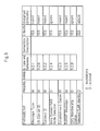
- FIG. 4 is a table showing the parameters that are described in a typical RUA Connect message.
- FIG. 5 is a table showing the parameters that are described in a RUA Connect message of the present exemplary embodiment.
- FIG. 4 shows the parameters of a RUA Connect message as stipulated in 25.468 V9.3.0 of 3GPP.
- the PLMN IDs indicating CNs to which a user terminal is to be connected cannot be set in a RUA Connect message.
- the Selected PLMN Identity is added as a parameter that can be set in a RUA Connect message.
- HNB 200 is able to set the PLMN IDs of CNs to which user terminal 100 is to be connected in this Selected PLMN Identity and notify HNB-GW 300.
- HNB-GW 300 is a gateway device that connects HNB 200 to a plurality of CNs 400-402 and is shared by a plurality of communication operators 10, 20, and 30.
- HNB-GW 300 receives from HNB 200 list information of the CNs to which HNB 200 is to be connected.
- HNB-GW 300 having received the list information, includes the paging areas in each CN to which HNB 200 is to belong in list information and holds this list information.
- HNB-GW 300 transfers a control message from the user terminal to the CNs that are indicated by the network identification information that was reported from HNB 200. For example, if the network identification information that was reported from HNB 200 at the time of call origination from user terminal 100 indicates CN 400, HNB-GW 300 transfers the control message from user terminal 100 to CN 400, whereby the control message from user terminal 100 can be transferred to CN 400 to which user terminal 100 subscribes.
- HNB-GW 300 selects the HNB to which paging is to be transmitted from a CN based on the list information that is held. It is here assumed that user terminal 100 is in the service area of HNB 200 and that call connection has occurred from CN 400 to user terminal 100. In this case, HNB-GW 300 transmits the paging from CN 400 to the base station device that belongs to the paging area that contains HNB 200.
- FIG. 2 shows only one HNB 200, but in actuality, a plurality of base station devices exists in the communication system.
- HNB-GW 300 having received the call connection message from CN 400 to user terminal 100, transmits the paging only to the base station device that belongs to that paging area.
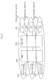
- FIG. 6 shows an example of the connection configuration when there is a plurality of HNBs in the same paging area.
- a plurality ofHNBs 200, 210, 220, 230, and 240 are shown in FIG. 6 .
- the PLMN IDs of the CNs to which each of HNBs 200-240 shown in the figure is connected are shown.
- PLMN ID 10
- HNB-GW 300 At the time of registration of HNB 200, list information of CNs that are to be connected is reported to HNB-GW 300, and at the time of call connection to a user terminal, HNB-GW 300 selects HNB 200 to which paging is to be transmitted based on the list information.
- HNB 200 reports to HNB-GW 300 network identification information of the CNs to which the user terminal is to be connected, and HNB-GW 300 transfers a control message from the user terminal to the core networks that are indicated by the network identification information.
- FIG. 7 is a block diagram showing the configuration of HNB 200.
- HNB 200 includes registration unit 201 and call control unit 202.
- HNB 200 is a base station device that connects with user terminals 100-102 by wireless lines and that connects with a plurality of CNs 400-402 by way of HNB-GW 300.
- Registration unit 201 carries out a process of registration of HNB 200 to CNs, and in this process, reports to HNB-GW 300 list information of the CNs that are to be connected.
- Call control unit 202 carries out processes of call origination and call connection of a user terminal, and in the call origination process, reports to HNB-GW 300, by means of a message of protocol for termination between HNB 200 and HNB-GW 300, network identification information that indicates CNs that are to be connected with the user terminal.
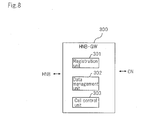
- FIG. 8 is a block diagram showing the configuration of HNB-GW 300.
- HNB-GW 300 includes registration unit 301, data management unit 302, and call control unit 303.
- HNB-GW 300 is a gateway device that connects HNB 200, which connects with user terminals 100-102 by wireless lines, to a plurality of CNs 400-402.
- Registration unit 301 carries out a process of registration of HNB 200 in CNs 400-402, and at this time, receives from HNB 200 list information of CNs 400-402 to which HNB 200 is to be connected.
- Data management unit 302 holds the list information that was received by registration unit 301. More specifically, data management unit 302 holds and manages information of the correspondence relation between CNs and PLMN IDs, information of the correspondence relation between HNBs and CNs that are connected to these HNBs, and information of the user terminals that are in the service areas of HNBs.
- the list information that was received by registration unit 301 is held as information of the correspondence relation between HNBs and the CNs that are connected to the HNBs.
- Call control unit 303 carries out a process of call origination from user terminals 100-102 and a process of call connection to user terminals 100-102. At these times, call control unit 303 receives from HNB 200 network identification information that indicates the CNs that are to be connected with a user terminal by means of a message of protocol for termination between an HNB and HNB-GW in the call origination process, and transfers the control message from a user terminal to the CNs that are indicated by the network identification information. In addition, in a call connection process, call control unit 303 selects HNB 200 to which paging from a CN is to be transmitted based on the list information that is held by data management unit 302.
- Call origination from user terminal 100 is here described as an example.
- Step 1-1 HNB 200 reports over wireless lines, to user terminals 100-102 by SIB18 (System Information Block 18) that conforms with TS 25.331 of 3GPP, a list of the PLMN IDs of a plurality of communication operators that are connected.
- SIB18 System Information Block 18
- Step 1-2 User terminal 100 selects the PLMN ID of communication operator 10 to which its own device subscribes from within the list of PLMN IDs that was reported and establishes an RRC connection with HNB 200.
- Step 1-3 HNB 200 sets the PLMN ID of communication operator 10 that is contained in the RRC message that was received from user terminal 100 in a RUA Connect message and transmits to HNB-GW 300.
- Step 1-4 Call control unit 303 of HNB-GW 300 that has received the RUA Connect message acquires the PLMN ID that is contained in the RUA Connect and acquires from data management unit 302 the information for CN 400 that corresponds to the PLMN ID.
- Step 1-5 Call control unit 303 of HNB-GW 300 transfers a RANAP Initial UE Message to this CN 400.
- HNB-GW 300 thus is able to route the RANAP Initial UE Message to CN 400, which is the appropriate transmission destination, without decoding the RANAP message.
- Step 2-1 When HNB 200 is started up, HNB 200 transmits an HNBAP HNB Register Request message to HNB-GW 300. At this time, HNB 200 sets in the message a list of the PLMN IDs of communication operators 10, 20, and 30 with which HNB 200 is to be connected.
- Step 2-2 Registration unit 301 of HNB-GW 300 that has received the HNBAP HNB Register Request message passes information indicating HNB 200 and the list of PLMN IDs that was reported to data management unit 302.
- Step 2-3 Data management unit 302 of HNB-GW 300 saves the information that was passed from registration unit 301.
- the procedure at the time of receiving paging in the present exemplary embodiment is next described.
- the communication system is here assumed to have the connection configuration of FIG. 6 .
- Step 3-1 HNB-GW 300 receives a RANAP Paging message from CN 400.
- Step 3-2 Call control unit 303 of HNB-GW 300 that has received the RANAP Paging message passes the information contained in the RANAP Paging message to data management unit 302.
- HNBs 200, 220, and 230 information that indicates HNB 200, HNB 220, and HNB 230, that are the transmission destinations of the RANAP Paging message, is therefore returned from data management unit 302 to call control unit 303.
- Step 3-3 HNB-GW 300 transmits a RUA Connectionless Transfer that carries the RANAP Paging message to HNB 200, HNB 220, and HNB 230.
- Step 3-2 The procedure of searching for the HNB that is the transmission destination of a RANAP Paging message in the above-described Step 3-2 is next described.
- Step 4-1 HNB-GW 300 judges whether location information exists in data management unit 302 regarding the location of user terminal 100, and if the information exists, extracts the information of the HNB of the location of user terminal 100. At this time, the existence or absence of the location information of user terminal 100 can be judged by whether or not the International Mobile Subscriber Intensity (IMSI) contained in the RANAP Paging message has been registered.
- IMSI International Mobile Subscriber Intensity
- Step 4-2 When the location information of user terminal 100 does not exist in data management unit 302, HNB-GW 300 extracts the Paging Area ID that has been set in the RANAP Paging message. HNB-GW 300 then extracts the HNB for which the PLMN ID, that is contained in the Paging Area ID, matches with the affiliated Paging area information (Location Area Code or Routing Area Code).
- HNB-GW 300 extracts the Paging Area ID that has been set in the RANAP Paging message.
- HNB-GW 300 then extracts the HNB for which the PLMN ID, that is contained in the Paging Area ID, matches with the affiliated Paging area information (Location Area Code or Routing Area Code).
Landscapes
- Engineering & Computer Science (AREA)
- Computer Networks & Wireless Communication (AREA)
- Signal Processing (AREA)
- Physics & Mathematics (AREA)
- Probability & Statistics with Applications (AREA)
- Mobile Radio Communication Systems (AREA)
Abstract
Description
- The present invention relates to communication system that connects with user terminals by femto-base stations, and in particular, relates to a communication system in which the core networks of a plurality of communication operators share femto-base stations.
- In UMTS (Universal Mobile Telecommunications System), there is a technology known as MOCN (Multi-Operator Core Network) for the sharing of wireless access networks by the core networks (CNs) of a plurality of communication operators (see
Patent Documents 1 and 2). - In MOCN, when a femto-base station (HNB: Home NodeB) is shared by a plurality of communication operators, the HNB is connected with a plurality of CNs by way of an HNB-GW (HNB-Gateway). When a call is originated from a user terminal, the HNB-GW must transfer a control message from the user terminal to the appropriate CN.
- At the time of starting up an HNB, the HNB must be connected to a plurality of CNs by way of an HNB-GW as described above. For this purpose, the plurality of CNs that are to connect with the HNB must be reported to the HNB-GW at the start-up time of the HNB.
-
- Patent Document 1: Japanese Unexamined Patent Application Publication No.
2008-535340 - Patent Document 2: Japanese Patent No.
4109695 - In MOCN, a control message is transferred by a RANAP (Radio Access Network Application Part) at the time of call origination from a user terminal that is connected to an HNB. A Selected PLMN (PublicLand MobileNetwork) Identity is contained in a RANAP Initial UE Message prescribed by 3GPP 25.423, and the CN selected by the user terminal can be designated by this Selected PLMN Identity in the RANAP Initial UE Message.
- As a result, the HNB-GW must decode this RANAP Initial UE Message to learn the CN to which the control message is to be transferred. However, if the RANAP version has been updated and the parameter of "criticality = reject" has been added, the possibility arises that the decoder will not correspond to the new version, whereby an Error Indication will be generated and HNB-GW will be unable to transfer the control message to the proper CN.
- Taking the role of an HNB-GW into consideration, a functional configuration of a system is preferable in which an HNB-GW need not decode a RANAP message. This is clear from the following sentence noted in 3GPP 25.468: "Additional information is provided to enable the HNB-GW to handle the RANAP message without it being necessary to inspect the contents and trigger the establishment of a new UE-associated Signaling Connection between HNB and HNB-GW, which is directly mapped to the Iu Signaling Connection the RANAP message refers to."
- In addition, in current protocol, only one PLMN ID can be set in an HNB Registration Request that is transmitted from the HNB to the HNB-GW at the time of HNB activation.
FIG. 1 is a table showing the parameters that are described in a typical HNB Registration Request message.FIG. 1 shows the parameters of an HNB Registration Request message as stipulated in 3GPP 25.469 V9.3.0. As can be seen from an inspection of this table, only one PLMN ID can be set in the HNB Registration Request. - Consequently, the PLMN IDs of a plurality of CNs to which an HNB is to be connected cannot be reported to the HNB-GW, and the HNB-GW is unable to properly connect the HNB with a plurality of CNs. As a result, at the time of connecting a call to a user terminal that is connected to the HNB of MOCN, the HNB-GW is unable to transfer Paging to the proper HNB of the intended transfer, and the possibility arises that normal call connection will not be possible.
- It is therefore an object of the present invention to provide a technology for sharing of a femto-base station by the core networks of a plurality of communication operators and for enabling normal call origination and connection of user terminals.
- The communication system of the present invention for achieving the above-described object includes a base station device that connects with a user terminal by a wireless line and a gateway device that connects the base station device with a plurality of core networks; wherein:
- at the time of registration of the base station device, the base station device reports to the gateway device list information of the core networks to which connection is to be implemented;
- at the time of call origination from the user terminal, the base station device reports to the gateway device, by means of a message of protocol for termination between a base station device and gateway device, network identification information that indicates core networks that are to be connected with the user terminal; and the gateway device transfers a control message from the user terminal to core networks that are indicated by the network identification information that was reported; and
- at the time of call connection to the user terminal, the gateway device, based on the list information that was reported from the base station device at the time of the registration, selects the base station devices to which paging from the core networks is to be transmitted.
- The base station device of the present invention is a base station device that connects to a user terminal by a wireless line and that connects to a plurality of core networks by way of a gateway device; the base station device including:
- a registration unit that carries out a process of registration of the base station device in core networks, and in this process, reports to the gateway device list information of core networks to which connection is to be implemented; and
- a call control unit that carries out a process of call origination from the user terminal, and in this process, that reports to the gateway device, by means of a message of protocol for termination between a base station device and gateway device, network identification information that indicates core networks that are to be connected to the user terminal.
- The gateway device of the present invention is a gateway device that connects a base station device that connects to a user terminal by a wireless line to a plurality of core networks, the gateway device including:
- a registration unit that carries out a process of registration of the base station device in core networks and that receives from the base station device list information of the core networks to which the base station device is to be connected;
- a data management unit that holds the list information that was received by the registration unit; and
- a call control unit that carries out processes of call origination from the user terminal and call connection to the user terminal, and in the call origination process, receives from the base station device, by means of a message of protocol for termination between a base station device and a gateway, network identification information that indicates core networks that are to be connected with the user terminal and transfers a control message from the user terminal to core networks indicated by the network identification information that was received; and in the call connection process, selects the base station device to which paging from core networks is to be transmitted based on the list information that is held by the data management unit.
- The base station device control method of the present invention is a base station device control method for controlling a base station device that connects to a user terminal by a wireless line and connects to a plurality of core networks by way of a gateway device, the base station device control method including steps of:
- in a process of registration of the base station device to core networks, reporting to the gateway device list information of core networks that are to be connected; and
- in a process of call origination from the user terminal, reporting to the gateway device, by means of a message of protocol for termination between a base station device and gateway device, network identification information that indicates core networks that are to be connected with the user terminal.
- The gateway device control method of the present invention is a gateway device control method for controlling a gateway device that connects a base station device that connects with a user terminal by a wireless line to a plurality of core networks, the gateway device control method including steps of:
- in a process of registration of the base station device in core networks, receiving from the base station device list information of core networks to which the base station device is to be connected and holding this list information;
- in a process of call origination from the user terminal, receiving from the base station device, by means of a message of protocol for termination between a base station device and gateway, network identification information that indicates core networks that are to be connected with the user terminal;
- transferring a control message from the user terminal to core networks that are indicated by the network identification information that was received; and
- in a process of call connection to the user terminal, selecting a base station device to which paging from the core networks is to be transmitted based on the list information that is held.
- According to the present invention, normal call origination and connection of a user terminal is possible in a communication system in which a base station device is shared by the core networks of a plurality of communication operators.
-
-
FIG. 1 is a table showing the parameters that are described in a typical HNB Registration Request message. -
FIG. 2 is a block diagram showing the configuration of the communication system of the present exemplary embodiment. -
FIG. 3 is a table showing the parameters that are described in an HNB Registration Request message according to the present exemplary embodiment. -
FIG. 4 is a table showing the parameters described in a typical RUA Connect message. -
FIG. 5 is a table showing the parameters described in a RUA Connect message of the present exemplary embodiment. -
FIG. 6 shows an example of the connection configuration when there is a plurality of HNB in the same paging area. -
FIG. 7 is a block diagram showing the configuration of HNB 200. -
FIG. 8 is a block diagram showing the configuration of HNB-GW 300. - An exemplary embodiment of the present invention is next described with reference to the accompanying drawings.
-
FIG. 2 is a block diagram showing the configuration of the communication system of the present exemplary embodiment. The communication system of the present exemplary embodiment is a UMTS system that allows MOCN by femto-base stations. - Referring to
FIG. 2 , HNB 200 is connected to a plurality of CNs 400-402 by way of HNB-GW 300. HNB 200 connects with a plurality of user terminals 100-102 by wireless lines. User terminals 100-102 are wireless communication terminals such as portable telephones or smartphones. CNs 400-402 are networks operated by mutually differing communication operators 10-30, connect calls of subscribing user terminals, and relay communication. User terminals 100-102 subscribe to the services of communication operators 10-30, respectively, and the terminals of each connect to respective CNs 400-402 of communication operators 10-30 to which they subscribe. -
HNB 200 is a base station device of a femtocell that connects with user terminals 100-102 by wireless lines and is shared bycommunication operators HNB 200 reports to HNB-GW 300 list information of CNs to which its own device is to connect. This list information can contain the network identification information of a plurality of CNs. In the example of the present exemplary embodiment, the list information contains network identification information of CNs 400-402, whereby user terminals 100-102 are able to connect with CNs 400-402 to which their own devices subscribe by way ofHNB 200. - More specifically, the stipulations of an HNBAP HNB Registration Request message as defined by 25.469 V9.3.0 of 3GPP have been modified in the present exemplary embodiment, and
HNB 200 is able to load a list of a plurality of PLMN IDs, which is list information, as a parameter in the HNBAP HNB Registration Request message and report this message to HNB-GW 300. -
FIG. 3 is a table showing the parameters that are described in an HNB Registration Request message according to the present exemplary embodiment. Comparing the table ofFIG. 3 according to the present exemplary embodiment with the table ofFIG. 1 , the parameter referred to as PLMN-ID List has been added inFIG. 3 . This parameter can describe a list of PLMN IDs of a number that, at a maximum, is the maximum number of PLMNs. - In addition, at the time of call origination from any user terminal,
HNB 200 reports to HNB-GW 300 by means of a message of protocol for termination between HNB and HNB-GW, network identification information that indicates the CNs to which the user terminal is to be connected. In the present exemplary embodiment, for example,user terminal 100 subscribes toCN 400, andHNB 200 therefore, at the time of call origination fromuser terminal 100, reports to HNB-GW 300 network identification information ofCN 400 to whichuser terminal 100 is to be connected. - More specifically, the stipulations of a RUA Connect message as defined in 25.468 V9.3.0 of 3GPP have been modified in the present exemplary embodiment, and
HNB 200 is able to load PLMN IDs, which are network identification information of CNs, as a parameter in a RUA Connect message and then notify HNB-GW 300. RUA (RANAP User Adaption) is a protocol for termination between HNB and HNB-GW. -
FIG. 4 is a table showing the parameters that are described in a typical RUA Connect message.FIG. 5 is a table showing the parameters that are described in a RUA Connect message of the present exemplary embodiment. -
FIG. 4 shows the parameters of a RUA Connect message as stipulated in 25.468 V9.3.0 of 3GPP. As can be understood by looking at this table, the PLMN IDs indicating CNs to which a user terminal is to be connected cannot be set in a RUA Connect message. - In contrast, in
FIG. 5 , the Selected PLMN Identity is added as a parameter that can be set in a RUA Connect message.HNB 200 is able to set the PLMN IDs of CNs to whichuser terminal 100 is to be connected in this Selected PLMN Identity and notify HNB-GW 300. - HNB-
GW 300 is a gateway device that connectsHNB 200 to a plurality of CNs 400-402 and is shared by a plurality ofcommunication operators - At the time of registration of
HNB 200, HNB-GW 300 receives fromHNB 200 list information of the CNs to whichHNB 200 is to be connected. HNB-GW 300, having received the list information, includes the paging areas in each CN to whichHNB 200 is to belong in list information and holds this list information. - At the time of call origination from a user terminal, HNB-
GW 300 transfers a control message from the user terminal to the CNs that are indicated by the network identification information that was reported fromHNB 200. For example, if the network identification information that was reported fromHNB 200 at the time of call origination fromuser terminal 100 indicatesCN 400, HNB-GW 300 transfers the control message fromuser terminal 100 toCN 400, whereby the control message fromuser terminal 100 can be transferred toCN 400 to whichuser terminal 100 subscribes. - In addition, at the time of call connection to any user terminal, HNB-
GW 300 selects the HNB to which paging is to be transmitted from a CN based on the list information that is held. It is here assumed thatuser terminal 100 is in the service area ofHNB 200 and that call connection has occurred fromCN 400 touser terminal 100. In this case, HNB-GW 300 transmits the paging fromCN 400 to the base station device that belongs to the paging area that containsHNB 200. -
FIG. 2 shows only oneHNB 200, but in actuality, a plurality of base station devices exists in the communication system. HNB-GW 300, having received the call connection message fromCN 400 touser terminal 100, transmits the paging only to the base station device that belongs to that paging area. -
FIG. 6 shows an example of the connection configuration when there is a plurality of HNBs in the same paging area. Aplurality ofHNBs FIG. 6 . The PLMN IDs of the CNs to which each of HNBs 200-240 shown in the figure is connected are shown. For example,HNB 200 is connected toCN 400 for which PLMN ID = 10 andCN 401 for which PLMN ID = 20. In addition,HNB 210 is connected toCN 401 for which PLMN ID = 20 andCN 402 for which PLMN ID = 30.HNB 220 is connected toCN 400 for which PLMN ID = 10 andCN 402 for which PLMN ID = 30.HNB 230 is connected toCN 400 for which PLMN ID = 10.HNB 240 is connected toCN 401 for which PLMN ID = 20. In the interest of simplifying the explanation, it is assumed that, of the HNB that appear, there are none that belong to different paging areas. - In the connection configuration of
FIG. 6 , when, for example, there is call connection touser terminal 100 fromCN 400, HNB-GW 300 transmits paging toHNBs user terminal 101 fromCN 401, HNB-GW 300 transmits paging toHNBs - According to the present exemplary embodiment as described hereinabove, at the time of registration of
HNB 200, list information of CNs that are to be connected is reported to HNB-GW 300, and at the time of call connection to a user terminal, HNB-GW 300 selectsHNB 200 to which paging is to be transmitted based on the list information. In addition, at the time of call origination from a user terminal,HNB 200 reports to HNB-GW 300 network identification information of the CNs to which the user terminal is to be connected, and HNB-GW 300 transfers a control message from the user terminal to the core networks that are indicated by the network identification information. As a result, proper call origination and connection of a user terminal becomes possible in a system configuration in which HNB is shared by a plurality of CNs. -
FIG. 7 is a block diagram showing the configuration ofHNB 200. Referring toFIG. 7 ,HNB 200 includesregistration unit 201 and callcontrol unit 202. - As described hereinabove,
HNB 200 is a base station device that connects with user terminals 100-102 by wireless lines and that connects with a plurality of CNs 400-402 by way of HNB-GW 300. -
Registration unit 201 carries out a process of registration ofHNB 200 to CNs, and in this process, reports to HNB-GW 300 list information of the CNs that are to be connected. - Call
control unit 202 carries out processes of call origination and call connection of a user terminal, and in the call origination process, reports to HNB-GW 300, by means of a message of protocol for termination betweenHNB 200 and HNB-GW 300, network identification information that indicates CNs that are to be connected with the user terminal. -
FIG. 8 is a block diagram showing the configuration of HNB-GW 300. Referring toFIG. 8 , HNB-GW 300 includesregistration unit 301,data management unit 302, and callcontrol unit 303. - As described hereinabove, HNB-
GW 300 is a gateway device that connectsHNB 200, which connects with user terminals 100-102 by wireless lines, to a plurality of CNs 400-402. -
Registration unit 301 carries out a process of registration ofHNB 200 in CNs 400-402, and at this time, receives fromHNB 200 list information of CNs 400-402 to whichHNB 200 is to be connected. -
Data management unit 302 holds the list information that was received byregistration unit 301. More specifically,data management unit 302 holds and manages information of the correspondence relation between CNs and PLMN IDs, information of the correspondence relation between HNBs and CNs that are connected to these HNBs, and information of the user terminals that are in the service areas of HNBs. The list information that was received byregistration unit 301 is held as information of the correspondence relation between HNBs and the CNs that are connected to the HNBs. - Call
control unit 303 carries out a process of call origination from user terminals 100-102 and a process of call connection to user terminals 100-102. At these times, callcontrol unit 303 receives fromHNB 200 network identification information that indicates the CNs that are to be connected with a user terminal by means of a message of protocol for termination between an HNB and HNB-GW in the call origination process, and transfers the control message from a user terminal to the CNs that are indicated by the network identification information. In addition, in a call connection process, callcontrol unit 303 selectsHNB 200 to which paging from a CN is to be transmitted based on the list information that is held bydata management unit 302. - The procedure at the time of call origination of the present exemplary embodiment is next described. Call origination from
user terminal 100 is here described as an example. - Step 1-1:
HNB 200 reports over wireless lines, to user terminals 100-102 by SIB18 (System Information Block 18) that conforms with TS 25.331 of 3GPP, a list of the PLMN IDs of a plurality of communication operators that are connected. - Step 1-2:
User terminal 100 selects the PLMN ID ofcommunication operator 10 to which its own device subscribes from within the list of PLMN IDs that was reported and establishes an RRC connection withHNB 200. - Step 1-3:
HNB 200 sets the PLMN ID ofcommunication operator 10 that is contained in the RRC message that was received fromuser terminal 100 in a RUA Connect message and transmits to HNB-GW 300. - Step 1-4: Call
control unit 303 of HNB-GW 300 that has received the RUA Connect message acquires the PLMN ID that is contained in the RUA Connect and acquires fromdata management unit 302 the information forCN 400 that corresponds to the PLMN ID. - Step 1-5: Call
control unit 303 of HNB-GW 300 transfers a RANAP Initial UE Message to thisCN 400. - HNB-
GW 300 thus is able to route the RANAP Initial UE Message toCN 400, which is the appropriate transmission destination, without decoding the RANAP message. - The procedure at the time of HNB registration of the present exemplary embodiment is next described.
- Step 2-1: When
HNB 200 is started up,HNB 200 transmits an HNBAP HNB Register Request message to HNB-GW 300. At this time,HNB 200 sets in the message a list of the PLMN IDs ofcommunication operators HNB 200 is to be connected. - Step 2-2:
Registration unit 301 of HNB-GW 300 that has received the HNBAP HNB Register Request message passesinformation indicating HNB 200 and the list of PLMN IDs that was reported todata management unit 302. - Step 2-3:
Data management unit 302 of HNB-GW 300 saves the information that was passed fromregistration unit 301. - The procedure at the time of receiving paging in the present exemplary embodiment is next described. The communication system is here assumed to have the connection configuration of
FIG. 6 . - Step 3-1: HNB-
GW 300 receives a RANAP Paging message fromCN 400. - Step 3-2: Call
control unit 303 of HNB-GW 300 that has received the RANAP Paging message passes the information contained in the RANAP Paging message todata management unit 302. In the information that is saved indata management unit 302, CN 400 (PLMN ID = 10) is connected toHNBs HNB 200,HNB 220, andHNB 230, that are the transmission destinations of the RANAP Paging message, is therefore returned fromdata management unit 302 to callcontrol unit 303. - Step 3-3: HNB-
GW 300 transmits a RUA Connectionless Transfer that carries the RANAP Paging message toHNB 200,HNB 220, andHNB 230. - The procedure of searching for the HNB that is the transmission destination of a RANAP Paging message in the above-described Step 3-2 is next described.
- Step 4-1: HNB-
GW 300 judges whether location information exists indata management unit 302 regarding the location ofuser terminal 100, and if the information exists, extracts the information of the HNB of the location ofuser terminal 100. At this time, the existence or absence of the location information ofuser terminal 100 can be judged by whether or not the International Mobile Subscriber Intensity (IMSI) contained in the RANAP Paging message has been registered. - Step 4-2: When the location information of
user terminal 100 does not exist indata management unit 302, HNB-GW 300 extracts the Paging Area ID that has been set in the RANAP Paging message. HNB-GW 300 then extracts the HNB for which the PLMN ID, that is contained in the Paging Area ID, matches with the affiliated Paging area information (Location Area Code or Routing Area Code). - Although the present invention has been described hereinabove with reference to an exemplary embodiment, the present invention is not limited to the above-described exemplary embodiment. The configuration and details of the present invention are open to various modifications within the scope of the present invention that will be clear to one of ordinary skill in the art.
- This application claims the benefits of priority based on Japanese Patent Application No.
2011-139511
Claims (9)
- A communication system having a base station device that connects with a user terminal by a wireless line and a gateway device that connects said base station device with a plurality of core networks; wherein:at the time of registration of said base station device, said base station device reports to said gateway device list information of core networks to which connection is to be implemented;at the time of call origination from said user terminal, said base station device reports to said gateway device, by means of a message of protocol for termination between a base station device and gateway device, network identification information that indicates core networks that are to be connected with said user terminal, and said gateway device transfers a control message from said user terminal to core networks that are indicated by said network identification information that was reported; andat the time of call connection to said user terminal, said gateway device, based on said list information that was reported from said base station device at the time of said registration, selects base station devices to which paging from said core networks is to be transmitted.
- The communication system as set forth in claim 1, wherein said base station device, at the time of said registration, loads a list of PLMN IDs, which are said list information, as a parameter into an HNBAP HNB Registration Request message and reports to said gateway device.
- The communication system as set forth in claim 1 or 2, wherein said base station device, at the time of call origination from said user terminal, loads PLMN IDs, which are said network identification information, as a parameter in a RUA Connect message and reports to said gateway device.
- A base station device that connects to a user terminal by a wireless line and that connects to a plurality of core networks by way of a gateway device; comprising:a registration unit that carries out a process of registration of said base station device in core networks, and in this process, reports to said gateway device list information of core networks to which connection is to be implemented; anda call control unit that carries out a call origination process from said user terminal, and in this process, reports to said gateway device, by means of a message of protocol for termination between a base station device and gateway device, network identification information that indicates core networks that are to be connected to said user terminal.
- The base station device as set forth in claim 4, wherein said registration unit loads in an HNBAP HNB Registration Request message a list of PLMN IDs, which is said list information, as a parameter and reports to said gateway device.
- The base station device as set forth in claim 4 or 5, wherein said call control unit, at the time of call origination from said user terminal, loads PLMN IDs, which is said network identification information, as a parameter in a RUA Connect message and reports to said gateway device.
- A gateway device that connects a base station device that connects to a user terminal by a wireless line to a plurality of core networks, comprising:a registration unit that carries out a process of registration of said base station device in core networks and that receives from said base station device list information of core networks to which said base station device is to be connected;a data management unit that holds said list information that was received by said registration unit; anda call control unit that carries out processes of call origination from said user terminal and call connection to said user terminal, and in said call origination process, receives from said base station device, by means of a message of protocol for termination between a base station device and a gateway, network identification information that indicates core networks that are to be connected with said user terminal, and transfers a control message from said user terminal to core networks indicated by said network identification information that was received, and in said call connection process, selects a base station device to which paging from said core networks is to be transmitted based on said list information that is held by said data management unit.
- A base station device control method for controlling a base station device that connects with a user terminal by a wireless line and connects to a plurality of core networks by way of a gateway device, comprising steps of:in a process of registration of the base station device to core networks, reporting to said gateway device list information of the core networks that are to be connected; andin a process of call origination from said user terminal, reporting to said gateway device, by means of a message of protocol for termination between a base station device and gateway device, network identification information that indicates core networks that are to be connected to said user terminal.
- A gateway device control method for controlling a gateway device that connects a base station device that connects with a user terminal by a wireless line to a plurality of core networks, comprising steps of:in a process of registration of said base station device in core networks, receiving from said base station device list information of core networks to which said base station device is to be connected and holding this list information;in a process of call origination from said user terminal, receiving from said base station device, by means of a message of protocol for termination between a base station device and gateway, network identification information that indicates core networks that are to be connected to said user terminal;transferring a control message from said user terminal to core networks that are indicated by said network identification information that was received; andin a process of call connection to said user terminal, selecting a base station device to which paging from said core networks is to be transmitted based on said list information that is held.
Applications Claiming Priority (2)
| Application Number | Priority Date | Filing Date | Title |
|---|---|---|---|
| JP2011139511 | 2011-06-23 | ||
| PCT/JP2012/060914 WO2012176545A1 (en) | 2011-06-23 | 2012-04-24 | Communication system, base station device, gateway device, method for controlling base station device, and method for controlling gateway device |
Publications (2)
| Publication Number | Publication Date |
|---|---|
| EP2725870A1 true EP2725870A1 (en) | 2014-04-30 |
| EP2725870A4 EP2725870A4 (en) | 2015-06-03 |
Family
ID=47422390
Family Applications (1)
| Application Number | Title | Priority Date | Filing Date |
|---|---|---|---|
| EP12802294.4A Withdrawn EP2725870A4 (en) | 2011-06-23 | 2012-04-24 | Communication system, base station device, gateway device, method for controlling base station device, and method for controlling gateway device |
Country Status (7)
| Country | Link |
|---|---|
| US (1) | US9313760B2 (en) |
| EP (1) | EP2725870A4 (en) |
| JP (1) | JP5772955B2 (en) |
| KR (1) | KR20140022084A (en) |
| CN (1) | CN103650629B (en) |
| BR (1) | BR112013032099A2 (en) |
| WO (1) | WO2012176545A1 (en) |
Cited By (1)
| Publication number | Priority date | Publication date | Assignee | Title |
|---|---|---|---|---|
| WO2013140808A1 (en) | 2012-03-23 | 2013-09-26 | Nec Corporation | Radio base station, communication node, control method for a radio base station and control method for a communication node |
Families Citing this family (8)
| Publication number | Priority date | Publication date | Assignee | Title |
|---|---|---|---|---|
| CN102036343B (en) * | 2009-09-27 | 2013-06-12 | 中兴通讯股份有限公司 | Femto sharing method and femto system |
| US9432906B2 (en) | 2013-09-12 | 2016-08-30 | Cisco Technology, Inc. | Handling connected mode mobility from areas bounding multi-operator core network and non-multi-operator core network shared infrastructure |
| US9521539B2 (en) * | 2014-06-05 | 2016-12-13 | Cisco Technology, Inc. | System and method for small cell gateway core network selection in a multi-operator core network environment |
| CN106559869B (en) * | 2015-09-30 | 2021-02-19 | 中兴通讯股份有限公司 | Registration initiating and processing method, base station controller, mobile station and system in MOCN (multimedia over cellular network) |
| US10880862B2 (en) * | 2019-04-24 | 2020-12-29 | Cisco Technology, Inc. | Paging for converged enterprise private radio service and Wi-Fi access deployments |
| CN114826829B (en) * | 2021-03-18 | 2023-07-14 | 几维通信技术(深圳)有限公司 | Mobile communication system for ocean environment |
| JP7739415B2 (en) * | 2021-03-31 | 2025-09-16 | ソフトバンク株式会社 | Relay device, relay method, and storage medium |
| CN115189755B (en) * | 2022-07-12 | 2023-11-21 | 联通航美网络有限公司 | VSAT and all-network communication 4G &5G base station integrated machine and operation method thereof |
Family Cites Families (13)
| Publication number | Priority date | Publication date | Assignee | Title |
|---|---|---|---|---|
| US7415274B2 (en) | 2003-02-19 | 2008-08-19 | Nokia Corporation | Routing procedure for a communication system |
| US7197312B2 (en) | 2003-11-12 | 2007-03-27 | Research In Motion Limited | Data-capable network prioritization with reject code handling |
| AU2005242125B2 (en) | 2004-12-07 | 2007-10-04 | Samsung Electronics Co., Ltd. | Method and apparatus for informing a radio access network of a selected core network from user equipment in a network sharing system |
| WO2006103093A2 (en) | 2005-03-31 | 2006-10-05 | Telefonaktiebolaget Lm Ericsson (Publ) | Technique for coordinating cs and ps registrations in a multi-operator core network |
| JP4651441B2 (en) | 2005-04-11 | 2011-03-16 | 株式会社エヌ・ティ・ティ・ドコモ | Mobile communication system and mobile device |
| CA2595740C (en) | 2006-08-02 | 2013-03-19 | Research In Motion Limited | Methods and applications for supporting radio access system selection by multi-mode mobile stations |
| US8219100B2 (en) * | 2007-08-31 | 2012-07-10 | Cellco Partnership | Active service redirection for a private femto cell |
| JP5538802B2 (en) | 2008-11-04 | 2014-07-02 | 三菱電機株式会社 | COMMUNICATION METHOD, MOBILE COMMUNICATION SYSTEM, MOBILE TERMINAL, AND BASE STATION CONTROL DEVICE |
| EP2209348A1 (en) * | 2009-01-14 | 2010-07-21 | Nokia Siemens Networks OY | Simplified home access |
| US8446836B2 (en) * | 2009-02-27 | 2013-05-21 | Broadcom Corporation | Method and system for supporting a plurality of providers via a single femtocell |
| RU2451427C1 (en) * | 2009-10-01 | 2012-05-20 | Нек Корпорейшн | Mobile communication system |
| EP2496017A4 (en) * | 2009-10-26 | 2016-12-28 | Nec Corp | MOBILE COMMUNICATION SYSTEM, GATEWAY DEVICE, BASE STATIONS, COMMUNICATION METHOD AND PROGRAM |
| CN102056273A (en) * | 2009-11-02 | 2011-05-11 | 中兴通讯股份有限公司 | Method and device for home evolved node B to select core network |
-
2012
- 2012-04-24 JP JP2013521498A patent/JP5772955B2/en not_active Expired - Fee Related
- 2012-04-24 BR BR112013032099A patent/BR112013032099A2/en not_active IP Right Cessation
- 2012-04-24 KR KR20137034796A patent/KR20140022084A/en not_active Abandoned
- 2012-04-24 WO PCT/JP2012/060914 patent/WO2012176545A1/en not_active Ceased
- 2012-04-24 CN CN201280030906.7A patent/CN103650629B/en not_active Expired - Fee Related
- 2012-04-24 EP EP12802294.4A patent/EP2725870A4/en not_active Withdrawn
- 2012-04-24 US US14/126,697 patent/US9313760B2/en not_active Expired - Fee Related
Cited By (3)
| Publication number | Priority date | Publication date | Assignee | Title |
|---|---|---|---|---|
| WO2013140808A1 (en) | 2012-03-23 | 2013-09-26 | Nec Corporation | Radio base station, communication node, control method for a radio base station and control method for a communication node |
| EP2829102A4 (en) * | 2012-03-23 | 2015-12-23 | Nec Corp | RADIO BASE STATION, COMMUNICATION NUMBER, METHOD FOR CONTROLLING RADIO BASE STATION, AND METHOD FOR CONTROLLING COMMUNICATION N UD |
| US9510370B2 (en) | 2012-03-23 | 2016-11-29 | Nec Corporation | Radio base station, communication node, control method for radio base station and control method for communication node |
Also Published As
| Publication number | Publication date |
|---|---|
| KR20140022084A (en) | 2014-02-21 |
| JPWO2012176545A1 (en) | 2015-02-23 |
| WO2012176545A1 (en) | 2012-12-27 |
| CN103650629B (en) | 2017-04-19 |
| EP2725870A4 (en) | 2015-06-03 |
| US9313760B2 (en) | 2016-04-12 |
| JP5772955B2 (en) | 2015-09-02 |
| CN103650629A (en) | 2014-03-19 |
| BR112013032099A2 (en) | 2016-12-13 |
| US20140120911A1 (en) | 2014-05-01 |
Similar Documents
| Publication | Publication Date | Title |
|---|---|---|
| US9313760B2 (en) | Communication system, base station device, gateway device, method for controlling base station device, and method for controlling gateway device, for enabling to connect user terminal to appropriate core network from among plurality of core networks when making or receiving call | |
| EP2934027A1 (en) | Wireless communication system | |
| CN101682874B (en) | Communication device, communication system and restricting method | |
| CN103621123A (en) | Traffic offload via local network | |
| CN109890088B (en) | Terminal device, base station and method for operating terminal device for wireless communication system | |
| US20110269468A1 (en) | Move subscribers to surrounding radio network | |
| US12323901B2 (en) | Cellular telecommunications network | |
| EP2930977A1 (en) | A method for operating a base station | |
| KR20160028512A (en) | Method for enhanced access selection by a user equipment in a cellular telecommunications network, telecommunications network, and system for enhanced access selection of a user equipment | |
| EP2166814A2 (en) | Wireless communication system, mobile station, wireless base station and communication method | |
| US9313731B2 (en) | Connection request for base stations that use the same frequency in the same coverage area | |
| EP3051863A1 (en) | Femto gateway and femto gateway control method | |
| CN117063604A (en) | Wireless communication system, wireless communication method, wireless communication program | |
| KR100942299B1 (en) | Wire / wireless communication system in premises and method for setting call signal using the system | |
| KR101395810B1 (en) | System and apparatus for connecting call in communication system and control method thereof | |
| EP2337381B1 (en) | Wireless base station, wireless network controller, and automatic networking method | |
| JP5257161B2 (en) | Network system, communication control method, and communication control program | |
| JP4820323B2 (en) | Communication network selection system | |
| JP7260644B2 (en) | Relay device and relay method | |
| KR101218235B1 (en) | Method and system for processing call forwarding services | |
| KR101313722B1 (en) | System and apparatus for connecting call in communication system and control method thereof | |
| WO2015178138A1 (en) | Radio communication system, first access node, second access node, and communication control method |
Legal Events
| Date | Code | Title | Description |
|---|---|---|---|
| PUAI | Public reference made under article 153(3) epc to a published international application that has entered the european phase |
Free format text: ORIGINAL CODE: 0009012 |
|
| 17P | Request for examination filed |
Effective date: 20140115 |
|
| AK | Designated contracting states |
Kind code of ref document: A1 Designated state(s): AL AT BE BG CH CY CZ DE DK EE ES FI FR GB GR HR HU IE IS IT LI LT LU LV MC MK MT NL NO PL PT RO RS SE SI SK SM TR |
|
| DAX | Request for extension of the european patent (deleted) | ||
| RA4 | Supplementary search report drawn up and despatched (corrected) |
Effective date: 20150504 |
|
| RIC1 | Information provided on ipc code assigned before grant |
Ipc: H04W 76/02 20090101ALN20150427BHEP Ipc: H04W 88/10 20090101AFI20150427BHEP Ipc: H04W 84/04 20090101ALN20150427BHEP Ipc: H04W 24/02 20090101ALI20150427BHEP |
|
| 17Q | First examination report despatched |
Effective date: 20180321 |
|
| STAA | Information on the status of an ep patent application or granted ep patent |
Free format text: STATUS: THE APPLICATION HAS BEEN WITHDRAWN |
|
| 18W | Application withdrawn |
Effective date: 20180511 |