EP2725779A2 - Method of compensating density and image forming apparatus performing the same - Google Patents
Method of compensating density and image forming apparatus performing the same Download PDFInfo
- Publication number
- EP2725779A2 EP2725779A2 EP13172439.5A EP13172439A EP2725779A2 EP 2725779 A2 EP2725779 A2 EP 2725779A2 EP 13172439 A EP13172439 A EP 13172439A EP 2725779 A2 EP2725779 A2 EP 2725779A2
- Authority
- EP
- European Patent Office
- Prior art keywords
- density
- compensation
- unit
- sensor unit
- transfer
- Prior art date
- Legal status (The legal status is an assumption and is not a legal conclusion. Google has not performed a legal analysis and makes no representation as to the accuracy of the status listed.)
- Granted
Links
Images



Classifications
-
- G—PHYSICS
- G03—PHOTOGRAPHY; CINEMATOGRAPHY; ANALOGOUS TECHNIQUES USING WAVES OTHER THAN OPTICAL WAVES; ELECTROGRAPHY; HOLOGRAPHY
- G03G—ELECTROGRAPHY; ELECTROPHOTOGRAPHY; MAGNETOGRAPHY
- G03G15/00—Apparatus for electrographic processes using a charge pattern
- G03G15/14—Apparatus for electrographic processes using a charge pattern for transferring a pattern to a second base
-
- G—PHYSICS
- G06—COMPUTING OR CALCULATING; COUNTING
- G06K—GRAPHICAL DATA READING; PRESENTATION OF DATA; RECORD CARRIERS; HANDLING RECORD CARRIERS
- G06K15/00—Arrangements for producing a permanent visual presentation of the output data, e.g. computer output printers
- G06K15/02—Arrangements for producing a permanent visual presentation of the output data, e.g. computer output printers using printers
- G06K15/027—Test patterns and calibration
-
- H—ELECTRICITY
- H04—ELECTRIC COMMUNICATION TECHNIQUE
- H04N—PICTORIAL COMMUNICATION, e.g. TELEVISION
- H04N1/00—Scanning, transmission or reproduction of documents or the like, e.g. facsimile transmission; Details thereof
- H04N1/40—Picture signal circuits
- H04N1/407—Control or modification of tonal gradation or of extreme levels, e.g. background level
- H04N1/4076—Control or modification of tonal gradation or of extreme levels, e.g. background level dependent on references outside the picture
- H04N1/4078—Control or modification of tonal gradation or of extreme levels, e.g. background level dependent on references outside the picture using gradational references, e.g. grey-scale test pattern analysis
-
- H—ELECTRICITY
- H04—ELECTRIC COMMUNICATION TECHNIQUE
- H04N—PICTORIAL COMMUNICATION, e.g. TELEVISION
- H04N1/00—Scanning, transmission or reproduction of documents or the like, e.g. facsimile transmission; Details thereof
- H04N1/46—Colour picture communication systems
- H04N1/56—Processing of colour picture signals
- H04N1/60—Colour correction or control
- H04N1/603—Colour correction or control controlled by characteristics of the picture signal generator or the picture reproducer
- H04N1/6033—Colour correction or control controlled by characteristics of the picture signal generator or the picture reproducer using test pattern analysis
-
- H—ELECTRICITY
- H04—ELECTRIC COMMUNICATION TECHNIQUE
- H04N—PICTORIAL COMMUNICATION, e.g. TELEVISION
- H04N1/00—Scanning, transmission or reproduction of documents or the like, e.g. facsimile transmission; Details thereof
- H04N1/40—Picture signal circuits
- H04N1/407—Control or modification of tonal gradation or of extreme levels, e.g. background level
Definitions
- the present disclosure relates to a method of compensating density, and more particularly, to a method of compensating a sensing value of a density sensor which is used in the density compensation operation.
- An image forming apparatus forms an image on a photoreceptor by supplying a developer containing toner when an electrostatic latent image is formed on the photoreceptor through an exposure process, and then transfers the image formed on the photoreceptor to a transfer medium and fixes the image with heat and pressure, thereby performing printing.
- the image formed on the photoreceptor when the image formed on the photoreceptor is transferred to the transfer medium, the image may not have a desired density due to environmental factors, such as temperature and humidity.
- sample patches are formed on the transfer medium, and power supply for the transfer is adjusted according to values obtained by sensing a density of the sample patches, thereby performing density compensation.
- the sensing capability of a density sensor for sensing the density of the samples patches varies due to various environmental factors, sensing errors may occur and the density compensation may not be correctly performed. Therefore, the sensing capability of the density sensor needs to be maintained constant by compensating the sensing values of the density sensor.
- the present disclosure provides a method of compensating density to minimize sensing errors.
- an image forming apparatus including: a transfer unit configured to transfer an image formed on a photoreceptor to a transfer medium; a power supply unit configured to supply transfer power to the transfer unit; a density sensor unit configured to sense a density of the image transferred to the transfer medium; and a control unit configured to control the power supply unit so that the transfer power supplied to the transfer unit is adjusted, wherein the density sensor unit is allowed to move from a first position for sensing a density of sample patches formed on the transfer medium to a second position for sensing a density of a reference reflective plate, and the control unit performs a sensor compensation mode, in which a sensing value of the density sensor unit is compensated according to a result of the density of the reference reflective plate sensed by the density sensor unit at the second position, and performs a density compensation mode in which the transfer power supplied to the transfer unit is adjusted according to the density of the sample patches sensed by the density sensor unit at the first position to thereby compensate the density of the image transferred to the transfer medium.
- the density sensor unit may rotate with respect to a hinge provided to one side of the density sensor unit to move from the first position to the second position.
- a distance between the density sensor unit and the transfer medium when the density sensor unit is located at the first position may be the same as that between the density sensor unit and the reference reflective plate when the density sensor unit is located at the second position.
- the control unit may include: a sensor compensation unit configured to compare the density of the reference reflective plate sensed by the density sensor unit at the second position with a reference value and calculate a compensation variable; and a density compensation unit configured to perform density compensation by applying the calculated compensation variable to the density of the sample patches sensed by the density sensor unit at the first position.
- the control unit may generate an image curve by using a value obtained by applying the compensation variable to the density of the sample patches, and may control the power supply unit so that the transfer power is adjusted according to a result of comparing a slope of the image curve with a predetermined (i.e. pre-stored) reference slope.
- the sensor compensation unit may calculate the compensation variable by dividing the reference value by the sensed density of the reference reflective plate, and the density compensation unit may perform the density compensation by using a value obtained by multiplying the sensed density of the sample patches by the compensation variable.
- a storage unit configured to store the compensation variable may be further included, wherein, when the compensation variable calculated by the sensor compensation unit does not match with the compensation variable stored in the storage unit, the compensation variable stored in the storage unit may be updated.
- the control unit may perform the sensor compensation mode while a printing mode in which printing data is printed is performed.
- the control unit may perform the sensor compensation mode right before performing the density compensation mode.
- the reference reflective plate may have brightness of N3.5 or more of the Munsell color system.
- a method of compensating density for an image forming apparatus including: performing a sensor compensation mode in which a sensing value of a density sensor unit is compensated; and performing a density compensation mode in which a density of an image formed on a transfer medium is compensated according to a result of sensing a density of sample patches formed on the transfer medium by using the density sensor unit, wherein the density sensor unit is located at a first position for sensing the density of the sample patches formed on the transfer medium when the density compensation mode is performed, and is located at a second position for sensing a density of a reference reflective plate when the sensor compensation mode is performed.
- the density sensor unit may rotate with respect to a hinge provided to one side of the density sensor unit to move from the first position to the second position.
- a distance between the density sensor unit and the transfer medium when the density sensor unit is located at the first position may be the same as that between the density sensor unit and the reference reflective plate when the density sensor unit is located at the second position.
- the performing of the sensor compensation mode may include: moving the density sensor unit from the first position to the second position; sensing the density of the reference reflective plate; and comparing the sensed density of the reference reflective plate with a reference value to calculate a compensation variable.
- the performing of the density compensation mode may include: moving the density sensor unit from the second position to the first position; forming the sample patches on the transfer medium; sensing the density of the formed sample patches; applying the calculated compensation variable to the sensed density of the sample patches; and compensating the density of the image formed on the transfer medium by adjusting transfer power according to the density of the sample patches to which the compensation variable is applied.
- the compensating of the density of the image may include: generating an image curve by using a value obtained by applying the compensation variable to the density of the sample patches; comparing a slope of the image curve with a prestored reference slope; and adjusting the transfer power according to a result of the comparison.
- the calculating of the compensation variable may include dividing the reference value by the sensed density of the reference reflective plate, and the compensating of the density of the image may include multiplying the sensed density of the sample patches by the compensation variable.
- the predetermined compensation variable may be updated.
- the sensor compensation mode may be performed while a printing mode in which printing data is printed is performed.
- FIG. 1 is a diagram illustrating an image forming apparatus according to an embodiment.
- the image forming apparatus may include a development unit 110, a transfer unit 120 including a primary transfer unit 120a and a secondary transfer unit 120b, a fusing unit 130, a power supply unit 140, a control unit 150, and a detection unit 160.
- the control unit 150 may include a density compensation unit 151 and a sensor compensation unit 152
- the detection unit 160 may include a density sensor unit 161 and a reference reflective plate 162.
- a hinge part 161a may be provided to one side of the density sensor unit 161 so that the density sensor unit 161 rotates with respect to the hinge part 161a.
- the image forming apparatus develops an image in the development unit 110 when image data are received from the outside.
- exposure units 111 to 114 radiate light to photoreceptors 115 to 118
- an electrostatic latent image is formed on the photoreceptors 115 to 118
- developer particles are charged and adhere to surfaces of the photoreceptors 115 to 118 to thereby form an image.
- FIG. 1 illustrates four exposure units 111 to 114 and four photoreceptors 115 to 118 since an image forming apparatus for forming a color image is typically provided with photoreceptors and exposure units for four colors of CMYK, i.e. cyan, magenta, yellow, and black, but the image forming apparatus according to an embodiment is not limited thereto.
- the image formed on the photoreceptors 115 to 118 is transferred from the primary transfer unit 120a to an intermediate transfer belt 127. Images for respective colors of cyan, magenta, yellow, and black may be sequentially transferred to the intermediate transfer belt 127 circulated by intermediate transfer rollers 125 and 126 so as to complete a single color image.
- the color image formed on the intermediate transfer belt 127 is transferred to a printing medium 102 supplied from the secondary transfer unit 120b.
- the drawing illustrates an indirect transfer method in which an image is firstly transferred from the photoreceptors 115 to 118 to the intermediate transfer belt 127 and then is secondly transferred from the intermediate transfer belt 127 to the printing medium 102, the image may also be directly transferred from the photoreceptors to the printing medium.
- the intermediate transfer belt 127 and the printing medium 102, to which images are transferred may be collectively referred to as a transfer medium.
- the printing medium 102 to which an image has been transferred is transported to the fusing unit 130 along a printing medium transport path 106 and is heated and pressed by fusing rollers 131 and 132. Therefore, an image is fused to the printing medium 102, and thus an image forming process is finished.
- a transfer process performed in the transfer unit 120 during the image forming process is described in detail as follows: To transfer the image formed on the photoreceptors 115 to 118 to the intermediate transfer belt 127, primary transfer rollers 121 to 124 are supplied with transfer power from the power supply unit 140 in order to apply a transfer voltage to the developer particles on the surfaces of the photoreceptors 115 to 118. That is, when a voltage, of which a polarity is opposite to that of the charged developer particles on the surfaces of the photoreceptors 115 to 118, is applied to each of the primary transfer rollers 121 to 124, the developer particles on the surfaces of the photoreceptors 115 to 118 are moved to the intermediate transfer belt 127 by electrostatic force.
- the secondary transfer unit 120b when a secondary transfer roller 128 is supplied with transfer power from the power supply unit 140 in order to apply a voltage of which a polarity is opposite to that of the charged developer particles on the intermediate transfer belt 127, the developer particles are moved from the intermediate transfer belt 127 to a surface of the printing medium 102 transported through the printing medium transport path 106.
- a density of a transferred image is determined by the transfer power.
- an intended density of an image may not match with a density of an actually outputted image. Therefore, in order to output an image with desired density, density compensation is performed.
- the density compensation is performed by using the detection unit 160 as described below.
- Sample patches with various coverages are formed on the intermediate transfer belt 127, and a density of the samples patches is sensed by the density sensor unit 161.
- an image curve is formed by using density sensing values according to the coverages of the sample patches.
- FIG. 3 illustrates an example of the image curve.
- the horizontal axis represents the coverages of the sample patches and the vertical axis represents the density of the sample patches.
- the two illustrated curves are image curves.
- a slope of the image curve is calculated. Then, according to a result of comparing the calculated slope with a predetermined (i.e. pre-stored) reference slope, the control unit 150 controls the power supply unit 140 to adjust the transfer power supplied to the primary and secondary transfer units 120a and 120b.
- the reference slope compared with the calculated slope of the image curve is a slope of an image curve formed by using reference density values of the sample patches according to the coverages of the sample patches.
- the reference density value is obtained through density sensing when the sample patches are formed with desired density.
- the density compensation is performed by the density sensor unit 161
- a sensing capability of the sensor may vary, and thus the density compensation may not be correctly performed. That is, since the density sensed by the density sensor unit 161 is different from the actual density of the sample patches, the density compensation may not be correctly performed.
- a sensing value of the density sensor unit 161 needs to be compensated.
- the reference reflective plate 162 and the hinge part 161a included in the detection unit 160 of the image forming apparatus are used to compensate the sensing value of the density sensor unit 161.
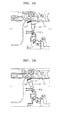
- FIGS. 2A and 2B are diagrams in detail illustrating motion of the density sensor unit 161 rotating with respect to the hinge part 161 a.
- the density sensor unit 161 is located at a position facing the intermediate transfer belt 127, and the hinge part 161a is provided to one side of the density sensor unit 161.
- the reference reflective plate 162 is provided to a side of the intermediate transfer belt 127 at a certain angle.
- the density sensor unit 161 may sense the density of the sample patches formed on the intermediate transfer belt 127.
- FIG. 2B illustrates that the density sensor unit 161 rotates with respect to the hinge part 161 a in order to sense the density of the reference reflective plate 162.
- the density sensor unit 161 compensates the sensing value as described below.
- the hinge part 161a is provided to one side of the density sensor unit 161, and the density sensor unit 161 is capable of rotating with respect to the hinge part 161 a.
- the density sensor unit 161 may rotate from a position for sensing the density of the image formed on the intermediate transfer belt 127 to a position for sensing the density of the reference reflective plate 162. After the density sensor unit 161 is moved to the position for sensing the density of the reference reflective plate 162 through a rotation, the density sensor unit 161 senses the density of the reference reflective plate 162.
- a distance d1 between the density sensor unit 161 and the intermediate transfer belt 127 when the density sensor unit 161 is located at the position facing the intermediate transfer belt 127 may be the same as a distance d2 between the density sensor unit 161 and the reference reflective plate 162 when the density sensor unit 161 is located at the position facing the reference reflective plate 162 so that sensing errors due to a difference between amounts of received light according to the distances may be reduced.
- FIG. 1 illustrates that the density sensor unit 161 rotates with respect to the hinge part 161a so that the density sensor unit 161 faces one of the intermediate transfer belt 127 and the reference reflective plate 162, the density sensor unit 161 may be moved by using a sliding mechanism.
- the reference reflective plate 162 is for compensating a sensing value for a color image, i.e. for performing calibration for diffused reflection waves.
- the reference reflective plate 162 may be a matt reflective plate having a rough surface.
- the reference reflective plate 162 may have brightness of N3.5 or more of the Munsell color system.
- the sensor compensation unit 152 compares a sensing value with a reference value to calculate a compensation variable.
- the compensation variable is obtained by dividing the reference value by an actual sensing value. For instance, when the reference value of the reference reflective plate 162 is 350 and the actual sensing value obtained by sensing the reference reflective plate 162 by the density sensor unit 161 is 318, the compensation variable is about 1.1.
- the reference value may be stored in a storage unit (not illustrated) included in the image forming apparatus, and the calculated compensation variable may also be stored in the storage unit.
- the density sensor unit 161 rotates again with respect to the hinge part 161a to sense the density of the sample patches formed on the intermediate transfer belt 127.
- the density compensation unit 151 applies the compensation variable to the density of the sensed sample patches to form an image curve. Thereafter, the density compensation unit 151 calculates a slope of the formed image curve, and compares the calculated slope with the reference slope to control the control unit 140 so that transfer power is adjusted.
- the density compensation unit 151 multiplies the density of the sensed sample patches by the compensation variable to form the image curve.
- Table 1 shows actual sensing values and compensation-variable-applied sensing values according to the coverages of the sample patches when the compensation variable is 1.17.
- Coverage Reference Sensing value Compensation variable Compensated sensing value 0.0 0.00 0.00 1.17 0.00 12.5 0.12 0.10 1.17 0.12 25.0 0.24 0.20 1.17 0.25 37.5 0.34 0.28 1.17 0.33 50.0 0.45 0.38 1.17 0.45 62.5 0.59 0.50 1.17 0.58 75.0 0.71 0.60 1.17 0.71 100.0 0.89 0.76 1.17 0.89
- the actual sensing values of the sample patches are a little bit different from the reference density values.
- the sensing values to which the compensation variable calculated during the sensing value compensation process of the density sensor unit 161 is applied are almost the same as the reference density values. That is, the actual density of the image transferred to the transfer medium is almost the same as the reference density value, but the sensing value obtained by sensing the density of the sample patches does not match with the actual density of the sample patches due to a problem of the density sensor unit 161.
- Image curves obtained by using the values of Table 1 are illustrated in FIG. 3 .
- an image curve obtained before applying the compensation variable and an image curve obtained after applying the compensation variable are illustrated.
- a slope of the image curve obtained after applying the compensation variable is calculated and compared with the reference slope in order to perform the density compensation.
- the reference slope is a slope of the image curve obtained by using the reference density values of Table 1.
- the mode, in which the compensating of the sensing value of the density compensation unit 161 is performed is referred to as a sensor compensation mode and the mode, in which the density of the image transferred to the transfer medium is compensated according to the value obtained by sensing the density of the sample patches, is referred to as a density compensation mode.
- FIG. 4 is a diagram illustrating the total printing time considering the operations of the density compensation and sensor compensation. As illustrated in FIG. 4 , by performing the sensor compensation mode that requires a time T1 while the printing is performed right before performing the density compensation mode that requires a time T1, the total printing time may be the same regardless of the performance of the sensor compensation mode.
- FIGS. 5 to 7 are flowcharts illustrating a method of compensating density, according to an embodiment.
- the sensor compensation mode for compensating the sensing value of the density sensor unit is performed. Thereafter, in operation S503, the density of the sample patches formed on the transfer medium may be sensed, and the density of the image formed on the transfer medium may be compensated by applying a result of the sensor compensation mode, so that the density compensation mode is performed.
- the density sensor unit is positioned so as to face the reference reflective plate, and when the density compensation mode is performed in operation S503, the density sensor unit is positioned so as to face the transfer medium.
- the density sensor unit may be configured so as to rotate with respect to the hinge part provided to one side of the density sensor unit.
- the density compensation mode of operation S501 may be performed while a printing mode, in which printing data is printed, is performed.
- the density sensor unit is rotated so as to face the reference reflective plate, and in operation S603, the density of the reference reflective plate is sensed by the density sensor unit and the sensing value is compared with the reference value to calculate the compensation variable.
- the compensation variable may be obtained by dividing the reference value by the value obtained by sensing the density of the reference reflective plate.
- the density sensor unit is rotated so as to face the transfer medium, and in operation S607, the density of the sample patches formed on the transfer medium is sensed. Thereafter, in operation S609, the calculated compensation variable is applied to the sensed density of the sample patches in order to perform the density compensation.
- the density compensation is performed by using a value obtained by multiplying the sensed density of the sample patches by the compensation variable.
- the density sensor unit is rotated so as to face the reference reflective plate, and in operation S703, the density of the reference reflective plate is sensed. Then, in operation S705, the sensed density value of the reference reflective plate is compared with the reference value to calculate the compensation variable.
- the compensation variable it is determined whether the calculated compensation variable is the same as the compensation variable predetermined (i.e. pre-stored) in a memory of the image forming apparatus. When the image forming apparatus is manufactured, the compensation variable may be stored as 1. If the calculated compensation variable does not match with the predetermined compensation variable according to a result of the determination of operation S707, the method proceeds to operation S708 in order to update the compensation variable.
- the method proceeds to operation S709.
- the density sensor unit is rotated so as to face the transfer medium.
- the sample patches are formed on the transfer medium, and in operation S713, the formed sample patches are sensed to output a sensing value.
- the stored compensation variable is applied to the sensing value outputted in operation S713 so as to form an image curve.
- the method of forming the image curve has been described in detail with reference to FIG. 3 .
- a slope of the image curve obtained in operation S715 is calculated, and the calculated sloped is compared with the reference slope.
- the transfer power is controlled to thereby perform the density compensation.
- the density sensor unit that can be positioned to face the transfer medium or the reference reflective plate, the sensor compensation mode and the density compensation mode are performed, and thus the sensing errors that may occur during the density compensation can be minimized.
Landscapes
- Engineering & Computer Science (AREA)
- Multimedia (AREA)
- Signal Processing (AREA)
- Physics & Mathematics (AREA)
- General Physics & Mathematics (AREA)
- General Engineering & Computer Science (AREA)
- Theoretical Computer Science (AREA)
- Control Or Security For Electrophotography (AREA)
- Electrostatic Charge, Transfer And Separation In Electrography (AREA)
Abstract
Description
- This application claims the benefit of Korean Patent Application No.
10-2012-0118673, filed on October 24, 2012 - The present disclosure relates to a method of compensating density, and more particularly, to a method of compensating a sensing value of a density sensor which is used in the density compensation operation.
- An image forming apparatus forms an image on a photoreceptor by supplying a developer containing toner when an electrostatic latent image is formed on the photoreceptor through an exposure process, and then transfers the image formed on the photoreceptor to a transfer medium and fixes the image with heat and pressure, thereby performing printing.
- However, when the image formed on the photoreceptor is transferred to the transfer medium, the image may not have a desired density due to environmental factors, such as temperature and humidity. To overcome this limitation, sample patches are formed on the transfer medium, and power supply for the transfer is adjusted according to values obtained by sensing a density of the sample patches, thereby performing density compensation.
- However, when a sensing capability of a density sensor for sensing the density of the samples patches varies due to various environmental factors, sensing errors may occur and the density compensation may not be correctly performed. Therefore, the sensing capability of the density sensor needs to be maintained constant by compensating the sensing values of the density sensor.
- Additional aspects and/or advantages will be set forth in part in the description which follows and, in part, will be apparent from the description, or may be learned by practice of the invention.
- The present disclosure provides a method of compensating density to minimize sensing errors.
- According to the present invention there is provided an apparatus and method as set forth in the appended claims. Other features of the invention will be apparent from the dependent claims, and the description which follows.
- According to an aspect, there is provided an image forming apparatus including: a transfer unit configured to transfer an image formed on a photoreceptor to a transfer medium; a power supply unit configured to supply transfer power to the transfer unit; a density sensor unit configured to sense a density of the image transferred to the transfer medium; and a control unit configured to control the power supply unit so that the transfer power supplied to the transfer unit is adjusted, wherein the density sensor unit is allowed to move from a first position for sensing a density of sample patches formed on the transfer medium to a second position for sensing a density of a reference reflective plate, and the control unit performs a sensor compensation mode, in which a sensing value of the density sensor unit is compensated according to a result of the density of the reference reflective plate sensed by the density sensor unit at the second position, and performs a density compensation mode in which the transfer power supplied to the transfer unit is adjusted according to the density of the sample patches sensed by the density sensor unit at the first position to thereby compensate the density of the image transferred to the transfer medium.
- The density sensor unit may rotate with respect to a hinge provided to one side of the density sensor unit to move from the first position to the second position.
- A distance between the density sensor unit and the transfer medium when the density sensor unit is located at the first position may be the same as that between the density sensor unit and the reference reflective plate when the density sensor unit is located at the second position.
- The control unit may include: a sensor compensation unit configured to compare the density of the reference reflective plate sensed by the density sensor unit at the second position with a reference value and calculate a compensation variable; and a density compensation unit configured to perform density compensation by applying the calculated compensation variable to the density of the sample patches sensed by the density sensor unit at the first position.
- The control unit may generate an image curve by using a value obtained by applying the compensation variable to the density of the sample patches, and may control the power supply unit so that the transfer power is adjusted according to a result of comparing a slope of the image curve with a predetermined (i.e. pre-stored) reference slope.
- The sensor compensation unit may calculate the compensation variable by dividing the reference value by the sensed density of the reference reflective plate, and the density compensation unit may perform the density compensation by using a value obtained by multiplying the sensed density of the sample patches by the compensation variable.
- A storage unit configured to store the compensation variable may be further included, wherein, when the compensation variable calculated by the sensor compensation unit does not match with the compensation variable stored in the storage unit, the compensation variable stored in the storage unit may be updated.
- The control unit may perform the sensor compensation mode while a printing mode in which printing data is printed is performed.
- The control unit may perform the sensor compensation mode right before performing the density compensation mode.
- The reference reflective plate may have brightness of N3.5 or more of the Munsell color system.
- According to one aspect, there is provided a method of compensating density for an image forming apparatus, including: performing a sensor compensation mode in which a sensing value of a density sensor unit is compensated; and performing a density compensation mode in which a density of an image formed on a transfer medium is compensated according to a result of sensing a density of sample patches formed on the transfer medium by using the density sensor unit, wherein the density sensor unit is located at a first position for sensing the density of the sample patches formed on the transfer medium when the density compensation mode is performed, and is located at a second position for sensing a density of a reference reflective plate when the sensor compensation mode is performed.
- The density sensor unit may rotate with respect to a hinge provided to one side of the density sensor unit to move from the first position to the second position.
- A distance between the density sensor unit and the transfer medium when the density sensor unit is located at the first position may be the same as that between the density sensor unit and the reference reflective plate when the density sensor unit is located at the second position.
- The performing of the sensor compensation mode may include: moving the density sensor unit from the first position to the second position; sensing the density of the reference reflective plate; and comparing the sensed density of the reference reflective plate with a reference value to calculate a compensation variable.
- The performing of the density compensation mode may include: moving the density sensor unit from the second position to the first position; forming the sample patches on the transfer medium; sensing the density of the formed sample patches; applying the calculated compensation variable to the sensed density of the sample patches; and compensating the density of the image formed on the transfer medium by adjusting transfer power according to the density of the sample patches to which the compensation variable is applied.
- The compensating of the density of the image may include: generating an image curve by using a value obtained by applying the compensation variable to the density of the sample patches; comparing a slope of the image curve with a prestored reference slope; and adjusting the transfer power according to a result of the comparison.
- The calculating of the compensation variable may include dividing the reference value by the sensed density of the reference reflective plate, and the compensating of the density of the image may include multiplying the sensed density of the sample patches by the compensation variable.
- When the calculated compensation variable does not match with a prestored compensation variable, the predetermined compensation variable may be updated.
- The sensor compensation mode may be performed while a printing mode in which printing data is printed is performed.
- The above and other features and advantages of the present disclosure will become more apparent by describing in detail exemplary embodiments thereof with reference to the attached drawings in which:
-
FIG. 1 is a diagram illustrating an image forming apparatus according to an embodiment; -
FIGS. 2A and 2B are diagrams illustrating motion of a density sensor unit rotating with respect to a hinge part in detail; -
FIG. 3 is a diagram illustrating an image curve formed by using values of Table 1; -
FIG. 4 is a diagram illustrating a total printing time considering operations of density compensation and sensor compensation; and -
FIGS. 5 to 7 are flowcharts illustrating a method of compensating density, according to an embodiment. - The present disclosure will now be described more fully with reference to the accompanying drawings, in which exemplary embodiments are shown.
-
FIG. 1 is a diagram illustrating an image forming apparatus according to an embodiment. Referring toFig. 1 , the image forming apparatus according to an embodiment may include adevelopment unit 110, a transfer unit 120 including aprimary transfer unit 120a and asecondary transfer unit 120b, afusing unit 130, apower supply unit 140, acontrol unit 150, and adetection unit 160. Thecontrol unit 150 may include adensity compensation unit 151 and asensor compensation unit 152, and thedetection unit 160 may include adensity sensor unit 161 and a referencereflective plate 162. Ahinge part 161a may be provided to one side of thedensity sensor unit 161 so that thedensity sensor unit 161 rotates with respect to thehinge part 161a. - The image forming apparatus according to an embodiment develops an image in the
development unit 110 when image data are received from the outside. In detail, whenexposure units 111 to 114 radiate light tophotoreceptors 115 to 118, an electrostatic latent image is formed on thephotoreceptors 115 to 118, and when a developer containing toner is supplied to the electrostatic latent image, developer particles are charged and adhere to surfaces of thephotoreceptors 115 to 118 to thereby form an image.FIG. 1 illustrates fourexposure units 111 to 114 and fourphotoreceptors 115 to 118 since an image forming apparatus for forming a color image is typically provided with photoreceptors and exposure units for four colors of CMYK, i.e. cyan, magenta, yellow, and black, but the image forming apparatus according to an embodiment is not limited thereto. - The image formed on the
photoreceptors 115 to 118 is transferred from theprimary transfer unit 120a to anintermediate transfer belt 127. Images for respective colors of cyan, magenta, yellow, and black may be sequentially transferred to theintermediate transfer belt 127 circulated byintermediate transfer rollers intermediate transfer belt 127 is transferred to aprinting medium 102 supplied from thesecondary transfer unit 120b. Although the drawing illustrates an indirect transfer method in which an image is firstly transferred from thephotoreceptors 115 to 118 to theintermediate transfer belt 127 and then is secondly transferred from theintermediate transfer belt 127 to theprinting medium 102, the image may also be directly transferred from the photoreceptors to the printing medium. Theintermediate transfer belt 127 and theprinting medium 102, to which images are transferred, may be collectively referred to as a transfer medium. - The
printing medium 102 to which an image has been transferred is transported to thefusing unit 130 along a printingmedium transport path 106 and is heated and pressed byfusing rollers printing medium 102, and thus an image forming process is finished. - A transfer process performed in the transfer unit 120 during the image forming process is described in detail as follows: To transfer the image formed on the
photoreceptors 115 to 118 to theintermediate transfer belt 127, primary transfer rollers 121 to 124 are supplied with transfer power from thepower supply unit 140 in order to apply a transfer voltage to the developer particles on the surfaces of thephotoreceptors 115 to 118. That is, when a voltage, of which a polarity is opposite to that of the charged developer particles on the surfaces of thephotoreceptors 115 to 118, is applied to each of the primary transfer rollers 121 to 124, the developer particles on the surfaces of thephotoreceptors 115 to 118 are moved to theintermediate transfer belt 127 by electrostatic force. Likewise, in thesecondary transfer unit 120b, when asecondary transfer roller 128 is supplied with transfer power from thepower supply unit 140 in order to apply a voltage of which a polarity is opposite to that of the charged developer particles on theintermediate transfer belt 127, the developer particles are moved from theintermediate transfer belt 127 to a surface of theprinting medium 102 transported through the printingmedium transport path 106. - A density of a transferred image is determined by the transfer power. However, due to various environmental factors, such as temperature and humidity, an intended density of an image may not match with a density of an actually outputted image. Therefore, in order to output an image with desired density, density compensation is performed. The density compensation is performed by using the
detection unit 160 as described below. - Sample patches with various coverages are formed on the
intermediate transfer belt 127, and a density of the samples patches is sensed by thedensity sensor unit 161. When sensing of the density of the sample patches is completed, an image curve is formed by using density sensing values according to the coverages of the sample patches.FIG. 3 illustrates an example of the image curve. InFIG. 3 , the horizontal axis represents the coverages of the sample patches and the vertical axis represents the density of the sample patches. The two illustrated curves are image curves. When the image curve is formed, a slope of the image curve is calculated. Then, according to a result of comparing the calculated slope with a predetermined (i.e. pre-stored) reference slope, thecontrol unit 150 controls thepower supply unit 140 to adjust the transfer power supplied to the primary andsecondary transfer units - Here, the reference slope compared with the calculated slope of the image curve is a slope of an image curve formed by using reference density values of the sample patches according to the coverages of the sample patches. The reference density value is obtained through density sensing when the sample patches are formed with desired density.
- However, in the case where the density compensation is performed by the
density sensor unit 161, due to a longitudinal change caused by contamination of a sensor or due to a life of the sensor, a sensing capability of the sensor may vary, and thus the density compensation may not be correctly performed. That is, since the density sensed by thedensity sensor unit 161 is different from the actual density of the sample patches, the density compensation may not be correctly performed. To overcome this limitation, a sensing value of thedensity sensor unit 161 needs to be compensated. The referencereflective plate 162 and thehinge part 161a included in thedetection unit 160 of the image forming apparatus according to an embodiment are used to compensate the sensing value of thedensity sensor unit 161. -
FIGS. 2A and 2B are diagrams in detail illustrating motion of thedensity sensor unit 161 rotating with respect to thehinge part 161 a. Referring toFIG. 2A , thedensity sensor unit 161 is located at a position facing theintermediate transfer belt 127, and thehinge part 161a is provided to one side of thedensity sensor unit 161. The referencereflective plate 162 is provided to a side of theintermediate transfer belt 127 at a certain angle. At the position illustrated inFIG. 2A , thedensity sensor unit 161 may sense the density of the sample patches formed on theintermediate transfer belt 127.FIG. 2B illustrates that thedensity sensor unit 161 rotates with respect to thehinge part 161 a in order to sense the density of the referencereflective plate 162. - The
density sensor unit 161 compensates the sensing value as described below. Thehinge part 161a is provided to one side of thedensity sensor unit 161, and thedensity sensor unit 161 is capable of rotating with respect to thehinge part 161 a. Thedensity sensor unit 161 may rotate from a position for sensing the density of the image formed on theintermediate transfer belt 127 to a position for sensing the density of the referencereflective plate 162. After thedensity sensor unit 161 is moved to the position for sensing the density of the referencereflective plate 162 through a rotation, thedensity sensor unit 161 senses the density of the referencereflective plate 162. - Referring to
FIG. 1 , a distance d1 between thedensity sensor unit 161 and theintermediate transfer belt 127 when thedensity sensor unit 161 is located at the position facing theintermediate transfer belt 127 may be the same as a distance d2 between thedensity sensor unit 161 and the referencereflective plate 162 when thedensity sensor unit 161 is located at the position facing the referencereflective plate 162 so that sensing errors due to a difference between amounts of received light according to the distances may be reduced. - Although
FIG. 1 illustrates that thedensity sensor unit 161 rotates with respect to thehinge part 161a so that thedensity sensor unit 161 faces one of theintermediate transfer belt 127 and the referencereflective plate 162, thedensity sensor unit 161 may be moved by using a sliding mechanism. - The reference
reflective plate 162 is for compensating a sensing value for a color image, i.e. for performing calibration for diffused reflection waves. The referencereflective plate 162 may be a matt reflective plate having a rough surface. The referencereflective plate 162 may have brightness of N3.5 or more of the Munsell color system. - If the
density sensor unit 161 senses the density of the referencereflective plate 162, thesensor compensation unit 152 compares a sensing value with a reference value to calculate a compensation variable. The compensation variable is obtained by dividing the reference value by an actual sensing value. For instance, when the reference value of the referencereflective plate 162 is 350 and the actual sensing value obtained by sensing the referencereflective plate 162 by thedensity sensor unit 161 is 318, the compensation variable is about 1.1. The reference value may be stored in a storage unit (not illustrated) included in the image forming apparatus, and the calculated compensation variable may also be stored in the storage unit. - When the compensation variable is calculated, the
density sensor unit 161 rotates again with respect to thehinge part 161a to sense the density of the sample patches formed on theintermediate transfer belt 127. When the sensing of the density of the sample patches is completed, thedensity compensation unit 151 applies the compensation variable to the density of the sensed sample patches to form an image curve. Thereafter, thedensity compensation unit 151 calculates a slope of the formed image curve, and compares the calculated slope with the reference slope to control thecontrol unit 140 so that transfer power is adjusted. - In detail, the
density compensation unit 151 multiplies the density of the sensed sample patches by the compensation variable to form the image curve. Table 1 below shows actual sensing values and compensation-variable-applied sensing values according to the coverages of the sample patches when the compensation variable is 1.17.[Table 1] Coverage Reference Sensing value Compensation variable Compensated sensing value 0.0 0.00 0.00 1.17 0.00 12.5 0.12 0.10 1.17 0.12 25.0 0.24 0.20 1.17 0.25 37.5 0.34 0.28 1.17 0.33 50.0 0.45 0.38 1.17 0.45 62.5 0.59 0.50 1.17 0.58 75.0 0.71 0.60 1.17 0.71 100.0 0.89 0.76 1.17 0.89 - Referring to Table 1, the actual sensing values of the sample patches are a little bit different from the reference density values. However, the sensing values to which the compensation variable calculated during the sensing value compensation process of the
density sensor unit 161 is applied are almost the same as the reference density values. That is, the actual density of the image transferred to the transfer medium is almost the same as the reference density value, but the sensing value obtained by sensing the density of the sample patches does not match with the actual density of the sample patches due to a problem of thedensity sensor unit 161. Image curves obtained by using the values of Table 1 are illustrated inFIG. 3 . - Referring to
FIG. 3 , an image curve obtained before applying the compensation variable and an image curve obtained after applying the compensation variable are illustrated. A slope of the image curve obtained after applying the compensation variable is calculated and compared with the reference slope in order to perform the density compensation. The reference slope is a slope of the image curve obtained by using the reference density values of Table 1. - Here, the mode, in which the compensating of the sensing value of the
density compensation unit 161 is performed, is referred to as a sensor compensation mode and the mode, in which the density of the image transferred to the transfer medium is compensated according to the value obtained by sensing the density of the sample patches, is referred to as a density compensation mode. By performing the sensor compensation mode right before performing the density compensation mode, errors that may occur due to environmental factors, such as temperature, may be minimized. - Since printing paper contacts the
intermediate transfer belt 127 while printing data is printed, the density compensation mode, which requires the sample patches to be formed on theintermediate transfer belt 127, cannot be performed. However, the sensor compensation mode may be performed even while the printing is performed since the sensor compensation mode may be performed just by rotating thedensity sensor unit 161 to face the referencereflective plate 162. Therefore, to minimize an increase in a total printing time, the sensor compensation mode may be performed while the printing is performed.FIG. 4 is a diagram illustrating the total printing time considering the operations of the density compensation and sensor compensation. As illustrated inFIG. 4 , by performing the sensor compensation mode that requires a time T1 while the printing is performed right before performing the density compensation mode that requires a time T1, the total printing time may be the same regardless of the performance of the sensor compensation mode. -
FIGS. 5 to 7 are flowcharts illustrating a method of compensating density, according to an embodiment. - Referring to
FIG. 5 , in operation S501, the sensor compensation mode for compensating the sensing value of the density sensor unit is performed. Thereafter, in operation S503, the density of the sample patches formed on the transfer medium may be sensed, and the density of the image formed on the transfer medium may be compensated by applying a result of the sensor compensation mode, so that the density compensation mode is performed. Here, when the sensor compensation mode is performed in operation S501, the density sensor unit is positioned so as to face the reference reflective plate, and when the density compensation mode is performed in operation S503, the density sensor unit is positioned so as to face the transfer medium. The density sensor unit may be configured so as to rotate with respect to the hinge part provided to one side of the density sensor unit. The density compensation mode of operation S501 may be performed while a printing mode, in which printing data is printed, is performed. - Referring to
FIG. 6 , in operation S601, the density sensor unit is rotated so as to face the reference reflective plate, and in operation S603, the density of the reference reflective plate is sensed by the density sensor unit and the sensing value is compared with the reference value to calculate the compensation variable. In detail, the compensation variable may be obtained by dividing the reference value by the value obtained by sensing the density of the reference reflective plate. When the calculating the compensation variable is completed, in operation S605, the density sensor unit is rotated so as to face the transfer medium, and in operation S607, the density of the sample patches formed on the transfer medium is sensed. Thereafter, in operation S609, the calculated compensation variable is applied to the sensed density of the sample patches in order to perform the density compensation. In detail, the density compensation is performed by using a value obtained by multiplying the sensed density of the sample patches by the compensation variable. - Referring to
FIG. 7 , in operation S701, the density sensor unit is rotated so as to face the reference reflective plate, and in operation S703, the density of the reference reflective plate is sensed. Then, in operation S705, the sensed density value of the reference reflective plate is compared with the reference value to calculate the compensation variable. In operation S707, it is determined whether the calculated compensation variable is the same as the compensation variable predetermined (i.e. pre-stored) in a memory of the image forming apparatus. When the image forming apparatus is manufactured, the compensation variable may be stored as 1. If the calculated compensation variable does not match with the predetermined compensation variable according to a result of the determination of operation S707, the method proceeds to operation S708 in order to update the compensation variable. Otherwise, if the calculated compensation variable matches with the predetermined compensation variable, the method proceeds to operation S709. In operation S709, the density sensor unit is rotated so as to face the transfer medium. In operation S711, the sample patches are formed on the transfer medium, and in operation S713, the formed sample patches are sensed to output a sensing value. In operation S715, the stored compensation variable is applied to the sensing value outputted in operation S713 so as to form an image curve. The method of forming the image curve has been described in detail with reference toFIG. 3 . In operation S717, a slope of the image curve obtained in operation S715 is calculated, and the calculated sloped is compared with the reference slope. In operation S719, according to a result of the slope comparison, the transfer power is controlled to thereby perform the density compensation. - As described above, by using the density sensor unit that can be positioned to face the transfer medium or the reference reflective plate, the sensor compensation mode and the density compensation mode are performed, and thus the sensing errors that may occur during the density compensation can be minimized.
- While the present disclosure has been particularly shown and described with reference to exemplary embodiments thereof, it will be understood by those of ordinary skill in the art that various changes in form and details may be made therein without departing from the spirit and scope of the present general inventive concept as defined by the following claims.
- Attention is directed to all papers and documents which are filed concurrently with or previous to this specification in connection with this application and which are open to public inspection with this specification, and the contents of all such papers and documents are incorporated herein by reference.
- All of the features disclosed in this specification (including any accompanying claims, abstract and drawings), and/or all of the steps of any method or process so disclosed, may be combined in any combination, except combinations where at least some of such features and/or steps are mutually exclusive.
- Each feature disclosed in this specification (including any accompanying claims, abstract and drawings) may be replaced by alternative features serving the same, equivalent or similar purpose, unless expressly stated otherwise. Thus, unless expressly stated otherwise, each feature disclosed is one example only of a generic series of equivalent or similar features.
- The invention is not restricted to the details of the foregoing embodiment(s). The invention extends to any novel one, or any novel combination, of the features disclosed in this specification (including any accompanying claims, abstract and drawings), or to any novel one, or any novel combination, of the steps of any method or process so disclosed.
Claims (15)
- An image forming apparatus comprising:a transfer unit configured to transfer an image formed on a photoreceptor to a transfer medium;a power supply unit configured to supply transfer power to the transfer unit;a density sensor unit configured to sense a density of the image transferred to the transfer medium; anda control unit configured to control the power supply unit so that the transfer power supplied to the transfer unit is adjusted,wherein the density sensor unit is allowed to move from a first position for sensing a density of sample patches formed on the transfer medium to a second position for sensing a density of a reference reflective plate, andthe control unit performs a sensor compensation mode, in which a sensing value of the density sensor unit is compensated according to the density of the reference reflective plate sensed by the density sensor unit at the second position, and performs a density compensation mode in which the transfer power supplied to the transfer unit is adjusted according to the density of the sample patches sensed by the density sensor unit at the first position to thereby compensate the density of the image transferred to the transfer medium.
- The image forming apparatus of claim 1, wherein the density sensor unit rotates with respect to a hinge provided to one side of the density sensor unit to move from the first position to the second position.
- The image forming apparatus of claim 1, wherein a distance between the density sensor unit and the transfer medium when the density sensor unit is located at the first position is the same as that between the density sensor unit and the reference reflective plate when the density sensor unit is located at the second position.
- The image forming apparatus of claim 1, wherein the control unit comprises:a sensor compensation unit configured to compare the density of the reference reflective plate sensed by the density sensor unit at the second position with a reference value and calculate a compensation variable; anda density compensation unit configured to perform density compensation by applying the calculated compensation variable to the density of the sample patches sensed by the density sensor unit at the first position.
- The image forming apparatus of claim 4, wherein the control unit generates an image curve by using a value obtained by applying the compensation variable to the density of the sample patches, and controls the power supply unit so that the transfer power is adjusted according to a result of comparing a slope of the image curve with a predetermined reference slope.
- The image forming apparatus of claim 4, wherein
the sensor compensation unit calculates the compensation variable by dividing the reference value by the sensed density of the reference reflective plate, and
the density compensation unit performs the density compensation by using a value obtained by multiplying the sensed density of the sample patches by the compensation variable. - The image forming apparatus of claim 4, further comprising a storage unit configured to store the compensation variable, wherein, when the compensation variable calculated by the sensor compensation unit does not match with the compensation variable stored in the storage unit, the compensation variable stored in the storage unit is updated.
- The image forming apparatus of claim 1, wherein the control unit performs the sensor compensation mode while a printing mode in which printing data is printed is performed.
- The image forming apparatus of claim 1, wherein the control unit performs the sensor compensation mode right before performing the density compensation mode.
- The image forming apparatus of claim 1, wherein the reference reflective plate has brightness of N3.5 or more of the Munsell color system.
- A method of compensating density for an image forming apparatus, the method comprising:performing a sensor compensation mode in which a sensing value of a density sensor unit is compensated; andperforming a density compensation mode in which a density of an image formed on a transfer medium is compensated according to a result of sensing a density of sample patches formed on the transfer medium by using the density sensor unit,wherein the density sensor unit is located at a first position for sensing the density of the sample patches formed on the transfer medium when the density compensation mode is performed, and is located at a second position for sensing a density of a reference reflective plate when the sensor compensation mode is performed.
- The method of claim 11, wherein the density sensor unit rotates with respect to a hinge provided to one side of the density sensor unit to move from the first position to the second position.
- The method of claim 11, wherein a distance between the density sensor unit and the transfer medium when the density sensor unit is located at the first position is the same as that between the density sensor unit and the reference reflective plate when the density sensor unit is located at the second position.
- The method of claim 11, wherein the performing of the sensor compensation mode comprises:moving the density sensor unit from the first position to the second position;sensing the density of the reference reflective plate; andcomparing the sensed density of the reference reflective plate with a reference value to calculate a compensation variable.
- A non-transitory computer-readable recording medium for recording a program for executing a method according to any of claims 11 through 14 on a computer.
Applications Claiming Priority (1)
| Application Number | Priority Date | Filing Date | Title |
|---|---|---|---|
| KR1020120118673A KR101953246B1 (en) | 2012-10-24 | 2012-10-24 | Method for compensating density and image forming apparatus performing the same |
Publications (3)
| Publication Number | Publication Date |
|---|---|
| EP2725779A2 true EP2725779A2 (en) | 2014-04-30 |
| EP2725779A3 EP2725779A3 (en) | 2017-01-11 |
| EP2725779B1 EP2725779B1 (en) | 2018-08-01 |
Family
ID=48745638
Family Applications (1)
| Application Number | Title | Priority Date | Filing Date |
|---|---|---|---|
| EP13172439.5A Not-in-force EP2725779B1 (en) | 2012-10-24 | 2013-06-18 | Method of compensating density and image forming apparatus performing the same |
Country Status (5)
| Country | Link |
|---|---|
| US (1) | US9639785B2 (en) |
| EP (1) | EP2725779B1 (en) |
| KR (1) | KR101953246B1 (en) |
| CN (1) | CN103777505B (en) |
| WO (1) | WO2014065613A1 (en) |
Families Citing this family (1)
| Publication number | Priority date | Publication date | Assignee | Title |
|---|---|---|---|---|
| CN110949015B (en) * | 2018-09-26 | 2021-12-14 | 海德堡印刷机械股份公司 | Two-stage density compensation method |
Family Cites Families (16)
| Publication number | Priority date | Publication date | Assignee | Title |
|---|---|---|---|---|
| JP2917620B2 (en) * | 1991-11-06 | 1999-07-12 | 松下電器産業株式会社 | Image density control device |
| JPH11289454A (en) * | 1997-11-28 | 1999-10-19 | Canon Inc | Image processing method, image processing apparatus, and storage medium storing computer-readable program |
| US7020404B2 (en) * | 2002-08-30 | 2006-03-28 | Oki Data Corporation | Image forming apparatus with color shift sensors that are shielded from toner |
| JP4293767B2 (en) * | 2002-08-30 | 2009-07-08 | シャープ株式会社 | Image forming control method and image forming apparatus |
| JP4311202B2 (en) * | 2003-12-26 | 2009-08-12 | ブラザー工業株式会社 | Image forming apparatus, image forming system, correction data update method, and program |
| JP4372645B2 (en) * | 2004-08-26 | 2009-11-25 | シャープ株式会社 | Image forming apparatus |
| JP4379350B2 (en) | 2005-02-21 | 2009-12-09 | コニカミノルタビジネステクノロジーズ株式会社 | Image forming apparatus |
| JP2007017483A (en) | 2005-07-05 | 2007-01-25 | Nagano Japan Radio Co | Image forming apparatus |
| JP2007256883A (en) | 2006-03-27 | 2007-10-04 | Nagano Japan Radio Co | Image forming apparatus |
| KR20080081817A (en) * | 2007-03-06 | 2008-09-10 | 삼성전자주식회사 | Image forming apparatus and control method thereof |
| JP4479791B2 (en) * | 2007-12-27 | 2010-06-09 | ブラザー工業株式会社 | Image forming apparatus |
| CN102338999B (en) | 2008-02-07 | 2014-07-30 | 株式会社理光 | Image forming apparatus and image density control method |
| JP2009186815A (en) | 2008-02-07 | 2009-08-20 | Sharp Corp | Image forming apparatus and image forming method |
| US8315673B2 (en) | 2010-01-12 | 2012-11-20 | Qualcomm Incorporated | Using a display to select a target object for communication |
| JP5767450B2 (en) | 2010-08-16 | 2015-08-19 | キヤノン株式会社 | Image forming apparatus |
| US8422899B2 (en) | 2010-12-13 | 2013-04-16 | Xerox Corporation | Method and apparatus for compensation of banding from multiple sources in marking platform |
-
2012
- 2012-10-24 KR KR1020120118673A patent/KR101953246B1/en not_active Expired - Fee Related
-
2013
- 2013-06-18 EP EP13172439.5A patent/EP2725779B1/en not_active Not-in-force
- 2013-07-02 US US13/933,724 patent/US9639785B2/en not_active Expired - Fee Related
- 2013-10-24 WO PCT/KR2013/009533 patent/WO2014065613A1/en not_active Ceased
- 2013-10-24 CN CN201310507589.XA patent/CN103777505B/en not_active Expired - Fee Related
Non-Patent Citations (1)
| Title |
|---|
| None |
Also Published As
| Publication number | Publication date |
|---|---|
| CN103777505B (en) | 2018-04-13 |
| CN103777505A (en) | 2014-05-07 |
| EP2725779A3 (en) | 2017-01-11 |
| KR101953246B1 (en) | 2019-02-28 |
| KR20140052523A (en) | 2014-05-07 |
| US9639785B2 (en) | 2017-05-02 |
| WO2014065613A1 (en) | 2014-05-01 |
| EP2725779B1 (en) | 2018-08-01 |
| US20140111833A1 (en) | 2014-04-24 |
Similar Documents
| Publication | Publication Date | Title |
|---|---|---|
| JP6137615B2 (en) | Image forming apparatus and image density control method | |
| US7421231B2 (en) | Image forming apparatus | |
| US9977361B2 (en) | Image forming apparatus and image forming system | |
| CN102187654A (en) | Adaptive exposure printing and printing system | |
| JP6672033B2 (en) | Image forming apparatus, image forming system, and program | |
| US9207611B2 (en) | Image forming apparatus and control method thereof | |
| CN109814346B (en) | Image forming apparatus and image forming method | |
| US10274865B2 (en) | Developing device and image forming apparatus | |
| JP2005132049A (en) | Chromaticity correction method and color image forming apparatus | |
| US8441699B2 (en) | Image forming device having color density correction | |
| US8948631B2 (en) | Image forming apparatus and density adjusting method | |
| EP2725779B1 (en) | Method of compensating density and image forming apparatus performing the same | |
| US10582075B2 (en) | Image forming apparatus and conveyance control method | |
| US9740134B2 (en) | Image forming apparatus that sets surface potential of photoreceptor drum to target electric potential with simple configuration | |
| JP7516127B2 (en) | Image forming device | |
| JP6414531B2 (en) | Image forming apparatus | |
| JP2007178665A (en) | Image forming apparatus | |
| JP4311236B2 (en) | Image forming apparatus and image density control method | |
| JP2004069948A (en) | Color image forming device | |
| JP2003337458A (en) | Image density detection device and image density control method using the same | |
| JP2017097033A (en) | Image forming apparatus | |
| JP2017068041A (en) | Image forming apparatus | |
| JP6922377B2 (en) | Image forming device and transfer control method | |
| JP2017097032A (en) | Image forming apparatus | |
| JP6922378B2 (en) | Image forming device and transfer control method |
Legal Events
| Date | Code | Title | Description |
|---|---|---|---|
| PUAI | Public reference made under article 153(3) epc to a published international application that has entered the european phase |
Free format text: ORIGINAL CODE: 0009012 |
|
| 17P | Request for examination filed |
Effective date: 20130618 |
|
| AK | Designated contracting states |
Kind code of ref document: A2 Designated state(s): AL AT BE BG CH CY CZ DE DK EE ES FI FR GB GR HR HU IE IS IT LI LT LU LV MC MK MT NL NO PL PT RO RS SE SI SK SM TR |
|
| AX | Request for extension of the european patent |
Extension state: BA ME |
|
| PUAL | Search report despatched |
Free format text: ORIGINAL CODE: 0009013 |
|
| AK | Designated contracting states |
Kind code of ref document: A3 Designated state(s): AL AT BE BG CH CY CZ DE DK EE ES FI FR GB GR HR HU IE IS IT LI LT LU LV MC MK MT NL NO PL PT RO RS SE SI SK SM TR |
|
| AX | Request for extension of the european patent |
Extension state: BA ME |
|
| RIC1 | Information provided on ipc code assigned before grant |
Ipc: H04N 1/407 20060101AFI20161207BHEP Ipc: H04N 1/60 20060101ALI20161207BHEP |
|
| STAA | Information on the status of an ep patent application or granted ep patent |
Free format text: STATUS: REQUEST FOR EXAMINATION WAS MADE |
|
| RAP1 | Party data changed (applicant data changed or rights of an application transferred) |
Owner name: S-PRINTING SOLUTION CO., LTD. |
|
| 17P | Request for examination filed |
Effective date: 20170303 |
|
| RBV | Designated contracting states (corrected) |
Designated state(s): AL AT BE BG CH CY CZ DE DK EE ES FI FR GB GR HR HU IE IS IT LI LT LU LV MC MK MT NL NO PL PT RO RS SE SI SK SM TR |
|
| GRAP | Despatch of communication of intention to grant a patent |
Free format text: ORIGINAL CODE: EPIDOSNIGR1 |
|
| STAA | Information on the status of an ep patent application or granted ep patent |
Free format text: STATUS: GRANT OF PATENT IS INTENDED |
|
| INTG | Intention to grant announced |
Effective date: 20180308 |
|
| GRAS | Grant fee paid |
Free format text: ORIGINAL CODE: EPIDOSNIGR3 |
|
| RAP1 | Party data changed (applicant data changed or rights of an application transferred) |
Owner name: HP PRINTING KOREA CO., LTD. |
|
| GRAA | (expected) grant |
Free format text: ORIGINAL CODE: 0009210 |
|
| STAA | Information on the status of an ep patent application or granted ep patent |
Free format text: STATUS: THE PATENT HAS BEEN GRANTED |
|
| AK | Designated contracting states |
Kind code of ref document: B1 Designated state(s): AL AT BE BG CH CY CZ DE DK EE ES FI FR GB GR HR HU IE IS IT LI LT LU LV MC MK MT NL NO PL PT RO RS SE SI SK SM TR |
|
| REG | Reference to a national code |
Ref country code: GB Ref legal event code: FG4D |
|
| REG | Reference to a national code |
Ref country code: CH Ref legal event code: EP Ref country code: AT Ref legal event code: REF Ref document number: 1025720 Country of ref document: AT Kind code of ref document: T Effective date: 20180815 |
|
| REG | Reference to a national code |
Ref country code: IE Ref legal event code: FG4D |
|
| REG | Reference to a national code |
Ref country code: DE Ref legal event code: R096 Ref document number: 602013041073 Country of ref document: DE |
|
| REG | Reference to a national code |
Ref country code: NL Ref legal event code: MP Effective date: 20180801 |
|
| REG | Reference to a national code |
Ref country code: LT Ref legal event code: MG4D |
|
| REG | Reference to a national code |
Ref country code: AT Ref legal event code: MK05 Ref document number: 1025720 Country of ref document: AT Kind code of ref document: T Effective date: 20180801 |
|
| PG25 | Lapsed in a contracting state [announced via postgrant information from national office to epo] |
Ref country code: PL Free format text: LAPSE BECAUSE OF FAILURE TO SUBMIT A TRANSLATION OF THE DESCRIPTION OR TO PAY THE FEE WITHIN THE PRESCRIBED TIME-LIMIT Effective date: 20180801 Ref country code: LT Free format text: LAPSE BECAUSE OF FAILURE TO SUBMIT A TRANSLATION OF THE DESCRIPTION OR TO PAY THE FEE WITHIN THE PRESCRIBED TIME-LIMIT Effective date: 20180801 Ref country code: IS Free format text: LAPSE BECAUSE OF FAILURE TO SUBMIT A TRANSLATION OF THE DESCRIPTION OR TO PAY THE FEE WITHIN THE PRESCRIBED TIME-LIMIT Effective date: 20181201 Ref country code: NL Free format text: LAPSE BECAUSE OF FAILURE TO SUBMIT A TRANSLATION OF THE DESCRIPTION OR TO PAY THE FEE WITHIN THE PRESCRIBED TIME-LIMIT Effective date: 20180801 Ref country code: BG Free format text: LAPSE BECAUSE OF FAILURE TO SUBMIT A TRANSLATION OF THE DESCRIPTION OR TO PAY THE FEE WITHIN THE PRESCRIBED TIME-LIMIT Effective date: 20181101 Ref country code: SE Free format text: LAPSE BECAUSE OF FAILURE TO SUBMIT A TRANSLATION OF THE DESCRIPTION OR TO PAY THE FEE WITHIN THE PRESCRIBED TIME-LIMIT Effective date: 20180801 Ref country code: NO Free format text: LAPSE BECAUSE OF FAILURE TO SUBMIT A TRANSLATION OF THE DESCRIPTION OR TO PAY THE FEE WITHIN THE PRESCRIBED TIME-LIMIT Effective date: 20181101 Ref country code: GR Free format text: LAPSE BECAUSE OF FAILURE TO SUBMIT A TRANSLATION OF THE DESCRIPTION OR TO PAY THE FEE WITHIN THE PRESCRIBED TIME-LIMIT Effective date: 20181102 Ref country code: FI Free format text: LAPSE BECAUSE OF FAILURE TO SUBMIT A TRANSLATION OF THE DESCRIPTION OR TO PAY THE FEE WITHIN THE PRESCRIBED TIME-LIMIT Effective date: 20180801 Ref country code: AT Free format text: LAPSE BECAUSE OF FAILURE TO SUBMIT A TRANSLATION OF THE DESCRIPTION OR TO PAY THE FEE WITHIN THE PRESCRIBED TIME-LIMIT Effective date: 20180801 Ref country code: RS Free format text: LAPSE BECAUSE OF FAILURE TO SUBMIT A TRANSLATION OF THE DESCRIPTION OR TO PAY THE FEE WITHIN THE PRESCRIBED TIME-LIMIT Effective date: 20180801 |
|
| PG25 | Lapsed in a contracting state [announced via postgrant information from national office to epo] |
Ref country code: HR Free format text: LAPSE BECAUSE OF FAILURE TO SUBMIT A TRANSLATION OF THE DESCRIPTION OR TO PAY THE FEE WITHIN THE PRESCRIBED TIME-LIMIT Effective date: 20180801 Ref country code: LV Free format text: LAPSE BECAUSE OF FAILURE TO SUBMIT A TRANSLATION OF THE DESCRIPTION OR TO PAY THE FEE WITHIN THE PRESCRIBED TIME-LIMIT Effective date: 20180801 Ref country code: AL Free format text: LAPSE BECAUSE OF FAILURE TO SUBMIT A TRANSLATION OF THE DESCRIPTION OR TO PAY THE FEE WITHIN THE PRESCRIBED TIME-LIMIT Effective date: 20180801 |
|
| PG25 | Lapsed in a contracting state [announced via postgrant information from national office to epo] |
Ref country code: RO Free format text: LAPSE BECAUSE OF FAILURE TO SUBMIT A TRANSLATION OF THE DESCRIPTION OR TO PAY THE FEE WITHIN THE PRESCRIBED TIME-LIMIT Effective date: 20180801 Ref country code: CZ Free format text: LAPSE BECAUSE OF FAILURE TO SUBMIT A TRANSLATION OF THE DESCRIPTION OR TO PAY THE FEE WITHIN THE PRESCRIBED TIME-LIMIT Effective date: 20180801 Ref country code: ES Free format text: LAPSE BECAUSE OF FAILURE TO SUBMIT A TRANSLATION OF THE DESCRIPTION OR TO PAY THE FEE WITHIN THE PRESCRIBED TIME-LIMIT Effective date: 20180801 Ref country code: EE Free format text: LAPSE BECAUSE OF FAILURE TO SUBMIT A TRANSLATION OF THE DESCRIPTION OR TO PAY THE FEE WITHIN THE PRESCRIBED TIME-LIMIT Effective date: 20180801 Ref country code: IT Free format text: LAPSE BECAUSE OF FAILURE TO SUBMIT A TRANSLATION OF THE DESCRIPTION OR TO PAY THE FEE WITHIN THE PRESCRIBED TIME-LIMIT Effective date: 20180801 |
|
| REG | Reference to a national code |
Ref country code: DE Ref legal event code: R097 Ref document number: 602013041073 Country of ref document: DE |
|
| PG25 | Lapsed in a contracting state [announced via postgrant information from national office to epo] |
Ref country code: DK Free format text: LAPSE BECAUSE OF FAILURE TO SUBMIT A TRANSLATION OF THE DESCRIPTION OR TO PAY THE FEE WITHIN THE PRESCRIBED TIME-LIMIT Effective date: 20180801 Ref country code: SM Free format text: LAPSE BECAUSE OF FAILURE TO SUBMIT A TRANSLATION OF THE DESCRIPTION OR TO PAY THE FEE WITHIN THE PRESCRIBED TIME-LIMIT Effective date: 20180801 Ref country code: SK Free format text: LAPSE BECAUSE OF FAILURE TO SUBMIT A TRANSLATION OF THE DESCRIPTION OR TO PAY THE FEE WITHIN THE PRESCRIBED TIME-LIMIT Effective date: 20180801 |
|
| PLBE | No opposition filed within time limit |
Free format text: ORIGINAL CODE: 0009261 |
|
| STAA | Information on the status of an ep patent application or granted ep patent |
Free format text: STATUS: NO OPPOSITION FILED WITHIN TIME LIMIT |
|
| 26N | No opposition filed |
Effective date: 20190503 |
|
| PG25 | Lapsed in a contracting state [announced via postgrant information from national office to epo] |
Ref country code: SI Free format text: LAPSE BECAUSE OF FAILURE TO SUBMIT A TRANSLATION OF THE DESCRIPTION OR TO PAY THE FEE WITHIN THE PRESCRIBED TIME-LIMIT Effective date: 20180801 |
|
| REG | Reference to a national code |
Ref country code: DE Ref legal event code: R082 Ref document number: 602013041073 Country of ref document: DE Representative=s name: SCHOPPE, ZIMMERMANN, STOECKELER, ZINKLER, SCHE, DE Ref country code: DE Ref legal event code: R081 Ref document number: 602013041073 Country of ref document: DE Owner name: HEWLETT-PACKARD DEVELOPMENT COMPANY, L.P., SPR, US Free format text: FORMER OWNER: HP PRINTING KOREA CO., LTD., SUWON-SI, GYEONGGI-DO, KR |
|
| REG | Reference to a national code |
Ref country code: GB Ref legal event code: 732E Free format text: REGISTERED BETWEEN 20191212 AND 20191218 |
|
| PG25 | Lapsed in a contracting state [announced via postgrant information from national office to epo] |
Ref country code: MC Free format text: LAPSE BECAUSE OF FAILURE TO SUBMIT A TRANSLATION OF THE DESCRIPTION OR TO PAY THE FEE WITHIN THE PRESCRIBED TIME-LIMIT Effective date: 20180801 |
|
| REG | Reference to a national code |
Ref country code: CH Ref legal event code: PL |
|
| REG | Reference to a national code |
Ref country code: BE Ref legal event code: MM Effective date: 20190630 |
|
| PG25 | Lapsed in a contracting state [announced via postgrant information from national office to epo] |
Ref country code: TR Free format text: LAPSE BECAUSE OF FAILURE TO SUBMIT A TRANSLATION OF THE DESCRIPTION OR TO PAY THE FEE WITHIN THE PRESCRIBED TIME-LIMIT Effective date: 20180801 |
|
| PG25 | Lapsed in a contracting state [announced via postgrant information from national office to epo] |
Ref country code: IE Free format text: LAPSE BECAUSE OF NON-PAYMENT OF DUE FEES Effective date: 20190618 |
|
| PG25 | Lapsed in a contracting state [announced via postgrant information from national office to epo] |
Ref country code: CH Free format text: LAPSE BECAUSE OF NON-PAYMENT OF DUE FEES Effective date: 20190630 Ref country code: BE Free format text: LAPSE BECAUSE OF NON-PAYMENT OF DUE FEES Effective date: 20190630 Ref country code: LU Free format text: LAPSE BECAUSE OF NON-PAYMENT OF DUE FEES Effective date: 20190618 Ref country code: LI Free format text: LAPSE BECAUSE OF NON-PAYMENT OF DUE FEES Effective date: 20190630 |
|
| PG25 | Lapsed in a contracting state [announced via postgrant information from national office to epo] |
Ref country code: PT Free format text: LAPSE BECAUSE OF FAILURE TO SUBMIT A TRANSLATION OF THE DESCRIPTION OR TO PAY THE FEE WITHIN THE PRESCRIBED TIME-LIMIT Effective date: 20181201 |
|
| PGFP | Annual fee paid to national office [announced via postgrant information from national office to epo] |
Ref country code: FR Payment date: 20201214 Year of fee payment: 9 |
|
| PG25 | Lapsed in a contracting state [announced via postgrant information from national office to epo] |
Ref country code: CY Free format text: LAPSE BECAUSE OF FAILURE TO SUBMIT A TRANSLATION OF THE DESCRIPTION OR TO PAY THE FEE WITHIN THE PRESCRIBED TIME-LIMIT Effective date: 20180801 |
|
| PG25 | Lapsed in a contracting state [announced via postgrant information from national office to epo] |
Ref country code: HU Free format text: LAPSE BECAUSE OF FAILURE TO SUBMIT A TRANSLATION OF THE DESCRIPTION OR TO PAY THE FEE WITHIN THE PRESCRIBED TIME-LIMIT; INVALID AB INITIO Effective date: 20130618 Ref country code: MT Free format text: LAPSE BECAUSE OF FAILURE TO SUBMIT A TRANSLATION OF THE DESCRIPTION OR TO PAY THE FEE WITHIN THE PRESCRIBED TIME-LIMIT Effective date: 20180801 |
|
| PGFP | Annual fee paid to national office [announced via postgrant information from national office to epo] |
Ref country code: DE Payment date: 20201214 Year of fee payment: 9 |
|
| PGFP | Annual fee paid to national office [announced via postgrant information from national office to epo] |
Ref country code: GB Payment date: 20210519 Year of fee payment: 9 |
|
| PG25 | Lapsed in a contracting state [announced via postgrant information from national office to epo] |
Ref country code: MK Free format text: LAPSE BECAUSE OF FAILURE TO SUBMIT A TRANSLATION OF THE DESCRIPTION OR TO PAY THE FEE WITHIN THE PRESCRIBED TIME-LIMIT Effective date: 20180801 |
|
| REG | Reference to a national code |
Ref country code: DE Ref legal event code: R119 Ref document number: 602013041073 Country of ref document: DE |
|
| GBPC | Gb: european patent ceased through non-payment of renewal fee |
Effective date: 20220618 |
|
| PG25 | Lapsed in a contracting state [announced via postgrant information from national office to epo] |
Ref country code: FR Free format text: LAPSE BECAUSE OF NON-PAYMENT OF DUE FEES Effective date: 20220630 |
|
| PG25 | Lapsed in a contracting state [announced via postgrant information from national office to epo] |
Ref country code: GB Free format text: LAPSE BECAUSE OF NON-PAYMENT OF DUE FEES Effective date: 20220618 Ref country code: DE Free format text: LAPSE BECAUSE OF NON-PAYMENT OF DUE FEES Effective date: 20230103 |