EP2725748A2 - Sensor system and communication device - Google Patents
Sensor system and communication device Download PDFInfo
- Publication number
- EP2725748A2 EP2725748A2 EP13185523.1A EP13185523A EP2725748A2 EP 2725748 A2 EP2725748 A2 EP 2725748A2 EP 13185523 A EP13185523 A EP 13185523A EP 2725748 A2 EP2725748 A2 EP 2725748A2
- Authority
- EP
- European Patent Office
- Prior art keywords
- communication device
- communication
- unit
- sensors
- slave
- Prior art date
- Legal status (The legal status is an assumption and is not a legal conclusion. Google has not performed a legal analysis and makes no representation as to the accuracy of the status listed.)
- Withdrawn
Links
Images


Classifications
-
- G—PHYSICS
- G05—CONTROLLING; REGULATING
- G05B—CONTROL OR REGULATING SYSTEMS IN GENERAL; FUNCTIONAL ELEMENTS OF SUCH SYSTEMS; MONITORING OR TESTING ARRANGEMENTS FOR SUCH SYSTEMS OR ELEMENTS
- G05B19/00—Program-control systems
- G05B19/02—Program-control systems electric
- G05B19/04—Program control other than numerical control, i.e. in sequence controllers or logic controllers
- G05B19/042—Program control other than numerical control, i.e. in sequence controllers or logic controllers using digital processors
-
- H—ELECTRICITY
- H04—ELECTRIC COMMUNICATION TECHNIQUE
- H04L—TRANSMISSION OF DIGITAL INFORMATION, e.g. TELEGRAPHIC COMMUNICATION
- H04L12/00—Data switching networks
- H04L12/28—Data switching networks characterised by path configuration, e.g. LAN [Local Area Networks] or WAN [Wide Area Networks]
- H04L12/40—Bus networks
- H04L12/403—Bus networks with centralised control, e.g. polling
-
- H—ELECTRICITY
- H04—ELECTRIC COMMUNICATION TECHNIQUE
- H04L—TRANSMISSION OF DIGITAL INFORMATION, e.g. TELEGRAPHIC COMMUNICATION
- H04L12/00—Data switching networks
- H04L12/28—Data switching networks characterised by path configuration, e.g. LAN [Local Area Networks] or WAN [Wide Area Networks]
- H04L12/40—Bus networks
- H04L12/407—Bus networks with decentralised control
- H04L12/413—Bus networks with decentralised control with random access, e.g. carrier-sense multiple-access with collision detection [CSMA-CD]
-
- H—ELECTRICITY
- H04—ELECTRIC COMMUNICATION TECHNIQUE
- H04L—TRANSMISSION OF DIGITAL INFORMATION, e.g. TELEGRAPHIC COMMUNICATION
- H04L12/00—Data switching networks
- H04L12/64—Hybrid switching systems
- H04L12/6418—Hybrid transport
-
- G—PHYSICS
- G05—CONTROLLING; REGULATING
- G05B—CONTROL OR REGULATING SYSTEMS IN GENERAL; FUNCTIONAL ELEMENTS OF SUCH SYSTEMS; MONITORING OR TESTING ARRANGEMENTS FOR SUCH SYSTEMS OR ELEMENTS
- G05B2219/00—Program-control systems
- G05B2219/20—Pc systems
- G05B2219/21—Pc I-O input output
- G05B2219/21094—Different connectors for serial transmission as function of machine or connected sensor
Definitions
- the present invention relates to a sensor system and a communication device, and in particular, relates to a technology for arranging a plurality of sensors in a distributed manner.
- a production line has a plurality of sensors provided therein.
- a PLC Programmable Logic Controller
- a control device controls a manufacturing machine in response to signals input from various sensors.
- input systems from the sensors need to be unified in order to simplify the system configuration.
- Japanese Patent 4294985 B1 discloses a technology in which sensor units and sensor relay units are connected to a master unit, and the input systems from the sensors to the control device are unified by the master unit.
- Japanese Patent 3852067 B1 discloses a communication system which includes a master unit and a plurality of slave units which are cascade-connected to the master unit.
- JP 4294985 B1 and JP 3852067 B1 the sensor relay units or the slave units are connected to each other in series, thus, in order to transmit the detection result of, for example, the sensor on the lowest layer to the master unit, many units perform relaying process of a signal. As a result, it can take time to transmit the signal from the sensor to the master unit.
- the present invention has been made in view of the above-mentioned problem, and an object of the present invention is to control the increase in a transmission time associated with additional installation of a sensor.
- a sensor system includes a master communication device connectable (e.g. physically and electrically) to a control device and a plurality of sensors, the master communication device being configured to store information received from each sensor in a memory and send the stored information to the control device; and a plurality of slave communication devices connectable (e.g. physically and electrically) to a plurality of sensors, each of the slave communication devices configured to store information received from the respective sensors in a memory and send the stored information to the master communication device.
- the plurality of slave communication devices are connected to the master communication device in a bus type arrangement.
- the plurality of slave communication devices and the master communication device may each be connected to a system bus.
- a sensor discrimination signal and detected information of the sensors are transmitted between each slave communication device and the sensors.
- the sensor discrimination signals and the detected information are transmitted between the master communication device and the each slave communication device.
- the sensor discrimination signal and the detected information are transmitted between the control device and the master communication device.
- a sensor can be additionally installed in the sensor system by additionally installing the slave communication device. Since the plurality of the slave communication devices are connected to the master communication device in a bus type arrangement, even when the slave communication device is additionally installed, communication between the master communication device and the additionally installed slave communication device can be established without the existing slave communication device relaying the communication. Therefore, a transmission time of the signal associated with the additional installation of a sensor can be prevented from increasing.
- the plurality of slave communication devices may be connected to the master communication device by a serial transmission line.
- the master communication device and each of the slave communication devices may be connected to one or more sensors by a serial transmission line and a parallel transmission line.
- Each of the slave communication devices may be connected to one or more sensors by a serial transmission line or a parallel transmission line.
- the master communication device may periodically check whether the slave communication device is activated, and communicate with the slave communication device which is activated.
- an activation-checking communication command may be periodically sent to the slave communication devices, and an identification of a slave communication device which is activated may be stored.
- the activation-checking communication command is a command for checking whether the slave communication device is activated, and the activation-checking communication command includes an instruction for making the slave communication device to send back a predetermined signal. Therefore, the slave communication device sends back the predetermined signal when receiving the activation-checking communication command.
- the master communication device can identify not only the slave communication device activated earlier than the master communication device but also the slave communication device activated later than the master communication device, and can carry out communication.
- each of the slave communication devices may send a signal to the master communication device in an order previously registered at the slave communication device.
- the master communication device may send a synchronization signal to the slave communication devices.
- the signal sending section may send the signal to the master communication device after a lapse of a waiting time calculated based on the order previously registered at the slave communication device.
- the slave communication device Since the slave communication device sends back the signal in order at different times, the signals can be efficiently sent to the master communication device from the plurality of slave communication devices connected in parallel to each other.
- a communication device is (e.g. physically and electrically) connectable to a control device and a plurality of sensors, configured to store information received from each sensor in a memory and to send the information stored in the memory to the control device.
- the communication device includes a first communication unit configured to communicate with the sensors; a second communication unit configured to communicate with the control device; and a third communication unit configured to communicate with a plurality of slave communication units, the plurality of slave communication units physically and electrically connected to a plurality of sensors which are different from the sensors connected to the communication device, each of the slave communication units storing information received from each sensor in a memory and sending the information stored in the memory to the communication device, and being connected to the communication device in a bus type arrangement.
- a sensor can be additionally installed by additionally installing the slave communication device. Since the plurality of the slave communication devices are connected to the master communication device in a bus type arrangement, even if a slave communication device is additionally installed, communication between the master communication device and the additionally installed slave communication device can be established without the existing slave communication device relaying the communication. Therefore, a transmission time of the signal associated with the additional installation of a sensor can be prevented from increasing.
- a sensor can be additionally installed by additionally installing the slave communication device. Since the plurality of the slave communication devices are connected to the master communication device in a bus type arrangement, even when the slave communication device is additionally installed, communication between the master communication device and the additionally installed slave communication device can be established without the existing slave communication device relaying the communication. Therefore, an increase in a transmission time of the signal associated with the additional installation of a sensor can be prevented from increasing.
- a photoelectric sensor system 1 will be described as an example of a sensor system. However, a sensor system other than a photoelectric sensor system may be used.
- the photoelectric sensor system 1 includes a communication unit 10, a plurality of distributed units 20 (20A, 20B), and a plurality of sensors 30 (30A-30N).
- the communication unit 10 is connected to a PLC 2 through a network such as a LAN (Local Area Network).
- a network such as a LAN (Local Area Network).
- the communication unit 10 is configured to communicate with the PLC 2 by using EtherCAT (registered trademark), CC-LINK (registered trademark), DeviceNET, and CompoNET, and the like.
- the distributed units 20A and 20B are connected to the communication unit 10 in parallel to each other.
- the distributed units 20A and 20B are connected to the communication unit 10 in a bus type arrangement.
- the two distributed units 20A and 20B are used, but the number of the distributed units is not limited to two, and a plurality of distributed units may be used.
- the distributed units 20A and 20B are configured to communicate with the communication unit 10 in serial communication. That is to say, the distributed units 20A and 20B are each physically connected to the communication unit 10 through a serial transmission line. Parallel communication may be used instead of or in addition to the serial communication. In other words, the distributed units 20A and 20B may be each physically connected to the communication unit 10 through a parallel transmission line.
- the communication unit 10 has a function of a master unit, and the distributed units 20A and 20B each have a function of a slave unit. Therefore, when the communication unit 10 is activated, the communication unit 10 checks whether the distributed units 20A and 20B each are activated. Further, in this embodiment, even if the distributed units are activated after the activation of the communication unit 10, the communication unit 10 periodically checks, in order to detect the activation of the distributed units, whether the distributed units 20A and 20B each are activated.
- the sensors 30A-30N are provided to the photoelectric sensor system 1 in a distributed manner.
- the sensors 30A-30F are connected physically and electrically to the communication unit 10.
- the sensors 30G-30I are connected physically and electrically to the distributed unit 20A.
- the sensor sensors 30J-30N are connected physically and electrically to the distributed unit 20B. It should be noted that the total number of the sensors 30 and the numbers of the sensors 30 connected to each of the communication unit 10 and the distributed units 20 are not limited to those numbers shown in Fig. 1 . For example, no sensor may be connected to the communication unit 10.
- the communication unit 10 stores information received from each of the sensors 30A-30F in a memory and sends the stored information to the PLC 2.
- the distributed unit 20A stores information received from each of the sensors 30G-30I in a memory and sends the stored information to the communication unit 10, and the communication unit 10 transmits the signal from the distributed unit 20A to the PLC 2.
- the distributed unit 20B stores information received from each of the sensors 30J-30N in a memory and sends the stored information to the communication unit 10, and the communication unit 10 transmits the signal from the distributed unit 20B to the PLC 2.
- the signals from the sensors 30A-30N are unified and transmitted to the PLC 2 by the communication unit 10.
- the sensor discrimination signal is an ON signal or an OFF signal for indicating whether a sensor 30 is active or inactive. For example, when a sensor 30 is active, the sensor discrimination signal thereof indicates ON. To the contrary, when a sensor 30 is inactive, the sensor discrimination signal indicates OFF.
- the detected information of a sensor 30 is, for example, a received light amount, a threshold value, and the like.
- each distributed unit 20 and each sensor 30 the sensor discrimination signal and the detected information of each sensor 30 are transmitted. Further, between the communication unit 10 and each distributed unit 20, the sensor discrimination signal and the detected information of each sensor 30 are transmitted. Further, between the PLC 2 and the communication unit 10, the sensor discrimination signal and the detected information of each sensor 30 are transmitted.
- the one of the distributed units 20 When a signal is transmitted from the communication unit 10 to one of the distributed units 20, the one of the distributed units 20 directly receives the signal from the communication unit 10 without other distributed unit. That is, when the distributed unit 20A receives a signal from the communication unit 10, the distributed unit 20B does not perform processing to the signal. In the same way, when the distributed unit 20B receives a signal from the communication unit 10, the distributed unit 20A does not perform processing to the signal.
- each distributed unit 20 and the communication unit 10 communicate directly to each other includes an embodiment in which, while a communication line connecting one of the distributed units and the communication unit 10 physically passes through another one of the distributed units, the another one of the distributed units does not perform processing to the communication between the one of the distributed units and the communication unit 10. That is to say, an embodiment in which, while a communication line connecting one of the distributed units and the communication unit 10 physically passes through another one of the distributed units, the another one of the distributed units does not perform processing to the communication between the one of the distributed units and the communication unit 10 is one of embodiments in which the distributed units 20 are connected in parallel (connected in a bus type arrangement) to the communication unit 10.
- the communication unit 10 includes an input connector 101 and an output connector 102 used for connection to the PLC 2, a connector 104 used for connection to the distributed unit 20, a connector 106 used for connection to the sensor 30, and a power input connector 108.
- the communication unit 10 further includes an MPU (Micro Processing Unit) 110, a communication ASIC (Application Specific Integrated Circuit) 112, a serial communication circuit 114, a parallel communication circuit 116, a serial communication circuit 118, and a power supply circuit 120.
- MPU Micro Processing Unit
- ASIC Application Specific Integrated Circuit
- the MPU 110 operates to integrally perform all processing on the communication unit 10.
- the communication ASIC 112 manages communication with the PLC 2. As described above, the communication unit 10 communicates with the PLC2 by using EtherCAT, CC-LINK, DeviceNET, CompoNET, and the like.
- the communication unit 10 and the distributed units 20A and 20B are connected to each other in a bus type arrangement.
- serial communication is used.
- parallel communication may be used.
- two communication lines are used, one for transmitting and the other for receiving.
- the sensor 30 is mounted on, for example, a side surface of the communication unit 10.
- parallel communication or serial communication is used.
- the communication unit 10 and the sensor 30 are physically connected to each other through a serial transmission line and a parallel transmission line.
- the communication unit 10 and the sensor 30 may be connected through one of a serial transmission line and a parallel transmission line.
- the distributed unit 20 includes a connector 202 used for connection to the communication unit 10, a connector 204 used for connection to the sensor 30, a power input connector 206, and a rotary switch 208.
- the distributed unit 20 further includes an MPU 210, a serial communication circuit 212 for communication with the communication unit 10, a serial communication circuit 214 for communication with the sensor 30, and a power supply circuit 216.
- the MPU 210 operates to integrally perform all processing on the distributed unit 20.
- the communication unit 10 and the distributed unit 20 are connected to each other in a bus type arrangement, and serial communication is used.
- the sensor 30 is mounted on, for example, a side surface of the distributed unit 20.
- serial communication is used, but parallel communication may be used.
- the distributed unit 20 and the sensor 30 are physically connected to each other through at least one of a serial transmission line and a parallel transmission line.
- the distributed unit 20 and the sensor 30 may be connected through a serial transmission line and a parallel transmission line.
- the communication unit 10 since the plurality of the distributed units 20 are provided in the photoelectric sensor system 1, for the communication unit 10 to communicate with each distributed unit 20 separately, an identification number of each distributed unit 20 needs to be identified. For this purpose, a user can set the identification number for each distributed unit 20 by using the rotary switch 208.
- the communication unit 10 can identify the distributed unit 20 of the transmission source of the received data, on the basis of the identification number included in the received data. In addition, if data to be transmitted from the communication unit 10 is configured to have an identification number, a command can be given to a desired distributed unit 20.
- the sensor 30 includes an amplifier unit 301 and a fiber unit 302.
- the amplifier unit 301 includes an openable cover rotatably fixed to a body case of the amplifier unit 301 and a frame contained in the body case.
- the amplifier unit 301 includes a display and an operation unit on the upper surface of the frame which is exposed when the openable cover is open.
- connector 304 and 306 are provided for connection to the communication unit 10, the distributed unit 20, or another amplifier unit 301.
- the plurality of the amplifier units 301 can be serially connected to the communication unit 10 or the distributed unit 20.
- a signal from one amplifier unit 301 which is connected to another amplifier unit 301 is transmitted to the communication unit 10 or the distributed unit 20 through the another amplifier unit 301.
- the fiber unit 302 is connected to the front wall of the amplifier unit 301.
- the fiber unit 302 includes a head, a projecting-side optical fiber, and a receiving-side optical fiber.
- an activation-checking communication command is sent to the distributed unit 20 at Step (hereinafter, abbreviated as S) 100.
- the activation-checking communication command is sequentially sent to each distributed unit 20. It should be noted that the number of the distributed unit 20 included in the photoelectric sensor system 1 and their identification numbers are previously registered at the communication unit 10 or the PLC 2 by using a personal computer and the like.
- the distributed unit 20 is configured to send back the identification number to the communication unit 10 upon receiving the activation-checking communication command from the communication unit 10.
- the communication unit 10 can identify an active distributed unit 20 from the identification number received after sending the activation-checking communication command.
- the communication unit 10 stores, as the identification number of the active distributed unit 20, the identification number of the distributed unit 20 which has sent back the identification number.
- the communication unit 10 starts communication with the active distributed units 20 at S106.
- an activation-checking communication command is sent to the distributed unit 20 having the identification number 1 at S200.
- communication unit 10 is received "1" as identification number from the distributed unit 20 (S202: YES)
- the communication unit 10 stores the received identification number 1 as the identification number N of the active distributed unit 20 at S204.
- the communication unit 10 communicates with the active distributed unit 20.
- the activation-checking communication command is sent to the distributed unit 20 having the identification number N+1 at S210.
- the communication unit 10 When the communication unit 10 is received "N+1" as the identification number from the distributed unit 20 (S212: YES), the communication unit 10 increments the identification number N of the active distributed unit 20 by 1 at S214. In short, the received identification number N+1 is stored as the identification number N of the active distributed unit 20. In this way, activation is checked in order from the distributed unit 20 having the identification number 1.
- the communication unit 10 sends the synchronization signal to all the distributed units at a predetermined time, for example, at a predetermined cycle.
- Each distributed unit 20 upon receiving the synchronization signal, sends back a signal indicating a detection result of the sensor 30 in a predetermined order. For example, each distributed unit 20 determines when to send back the signal, from the identification number. In this embodiment, the signal is sent back the identification number of the distributed unit 20 in ascending order.
- TW N - 1 ⁇ ⁇
- the distributed units 20 sends back the signals at different times in order; thus, the signals can be efficiently sent from the plurality of the distributed units 20 connected in parallel to each other to the communication unit 10.
- the communication unit 10 sends the synchronization signals to the distributed units 20 at a predetermined cycle (for example, 100 ⁇ s). For example, the communication unit 10 send the synchronization signals to the three distributed units 20 to which the identification numbers 1 to 3 are assigned, respectively, and the communication unit 10 then sends the synchronization signals to the three distributed units 20 to which the identification numbers 4 to 6 are assigned, respectively. In addition, the communication unit 10 then sends the synchronization signals to the three distributed units 20 to which the identification numbers 7 to 9 are assigned, respectively.
- a predetermined cycle for example, 100 ⁇ s.
- the communication unit 10 send the synchronization signals to the three distributed units 20 to which the identification numbers 1 to 3 are assigned, respectively, and the communication unit 10 then sends the synchronization signals to the three distributed units 20 to which the identification numbers 4 to 6 are assigned, respectively.
- the communication unit 10 then sends the synchronization signals to the three distributed units 20 to which the identification numbers 7 to 9 are assigned, respectively.
- the three distributed units 20, to which the identification numbers 1 to 3 are assigned, respectively, each send back the signal in order after receiving the first synchronization signal.
- the synchronization signals are sent three times per one cycle.
- the number of times that the synchronization signals are sent is not limited to 3 and may be changed depending on the number of the distributed units 20 and the time TR that the distributed unit 20 takes to send the signal.
- Fig. 10 shows an example in which the RS-422 protocol is used for the serial communication.
- the signal is sent back from the distributed unit 20 after the communication unit 10 completes to send the synchronization signal. That is to say, the time for sending the synchronization signal and the time for sending back the signal from the distributed unit 20 do not overlap.
- the photoelectric sensor system 1 can include an additional sensor 30 by additionally installing another distributed unit 20.
- the plurality of distributed units 20 are connected to the communication unit 10 in a bus type arrangement, and even when the distributed unit 20 is additionally installed, the communication between the communication unit 10 and the additionally installed distributed unit 20 can be established without the existing distributed units 20 relaying the communication. Therefore, the increase in the transmission time of a signal associated with the additional installation of the sensor 30 can be controlled.
Landscapes
- Engineering & Computer Science (AREA)
- Computer Networks & Wireless Communication (AREA)
- Signal Processing (AREA)
- Physics & Mathematics (AREA)
- General Physics & Mathematics (AREA)
- Automation & Control Theory (AREA)
- Arrangements For Transmission Of Measured Signals (AREA)
- Small-Scale Networks (AREA)
Abstract
Description
- The present invention relates to a sensor system and a communication device, and in particular, relates to a technology for arranging a plurality of sensors in a distributed manner.
- In general, a production line has a plurality of sensors provided therein. A PLC (Programmable Logic Controller) as a control device controls a manufacturing machine in response to signals input from various sensors. In such a manufacturing system, input systems from the sensors need to be unified in order to simplify the system configuration.
- To satisfy this need, Japanese Patent
4294985 B1 3852067 B1 - However, in
JP 4294985 B1 JP 3852067 B1 - The present invention has been made in view of the above-mentioned problem, and an object of the present invention is to control the increase in a transmission time associated with additional installation of a sensor.
- In one embodiment, a sensor system includes a master communication device connectable (e.g. physically and electrically) to a control device and a plurality of sensors, the master communication device being configured to store information received from each sensor in a memory and send the stored information to the control device; and a plurality of slave communication devices connectable (e.g. physically and electrically) to a plurality of sensors, each of the slave communication devices configured to store information received from the respective sensors in a memory and send the stored information to the master communication device. The plurality of slave communication devices are connected to the master communication device in a bus type arrangement. For example, the plurality of slave communication devices and the master communication device may each be connected to a system bus. A sensor discrimination signal and detected information of the sensors are transmitted between each slave communication device and the sensors. The sensor discrimination signals and the detected information are transmitted between the master communication device and the each slave communication device. The sensor discrimination signal and the detected information are transmitted between the control device and the master communication device.
- With this configuration, a sensor can be additionally installed in the sensor system by additionally installing the slave communication device. Since the plurality of the slave communication devices are connected to the master communication device in a bus type arrangement, even when the slave communication device is additionally installed, communication between the master communication device and the additionally installed slave communication device can be established without the existing slave communication device relaying the communication. Therefore, a transmission time of the signal associated with the additional installation of a sensor can be prevented from increasing.
- The plurality of slave communication devices may be connected to the master communication device by a serial transmission line. The master communication device and each of the slave communication devices may be connected to one or more sensors by a serial transmission line and a parallel transmission line. Each of the slave communication devices may be connected to one or more sensors by a serial transmission line or a parallel transmission line.
- The master communication device may periodically check whether the slave communication device is activated, and communicate with the slave communication device which is activated. In this case, as a way of checking, an activation-checking communication command may be periodically sent to the slave communication devices, and an identification of a slave communication device which is activated may be stored. The activation-checking communication command is a command for checking whether the slave communication device is activated, and the activation-checking communication command includes an instruction for making the slave communication device to send back a predetermined signal. Therefore, the slave communication device sends back the predetermined signal when receiving the activation-checking communication command.
- By periodically checking whether the slave communication device is activated, the master communication device can identify not only the slave communication device activated earlier than the master communication device but also the slave communication device activated later than the master communication device, and can carry out communication.
- Upon receiving a command from the master communication device, each of the slave communication devices may send a signal to the master communication device in an order previously registered at the slave communication device. In this case, the master communication device may send a synchronization signal to the slave communication devices. The signal sending section may send the signal to the master communication device after a lapse of a waiting time calculated based on the order previously registered at the slave communication device.
- Since the slave communication device sends back the signal in order at different times, the signals can be efficiently sent to the master communication device from the plurality of slave communication devices connected in parallel to each other.
- In another embodiment, a communication device is (e.g. physically and electrically) connectable to a control device and a plurality of sensors, configured to store information received from each sensor in a memory and to send the information stored in the memory to the control device. The communication device includes a first communication unit configured to communicate with the sensors; a second communication unit configured to communicate with the control device; and a third communication unit configured to communicate with a plurality of slave communication units, the plurality of slave communication units physically and electrically connected to a plurality of sensors which are different from the sensors connected to the communication device, each of the slave communication units storing information received from each sensor in a memory and sending the information stored in the memory to the communication device, and being connected to the communication device in a bus type arrangement.
- With this configuration, a sensor can be additionally installed by additionally installing the slave communication device. Since the plurality of the slave communication devices are connected to the master communication device in a bus type arrangement, even if a slave communication device is additionally installed, communication between the master communication device and the additionally installed slave communication device can be established without the existing slave communication device relaying the communication. Therefore, a transmission time of the signal associated with the additional installation of a sensor can be prevented from increasing.
- A sensor can be additionally installed by additionally installing the slave communication device. Since the plurality of the slave communication devices are connected to the master communication device in a bus type arrangement, even when the slave communication device is additionally installed, communication between the master communication device and the additionally installed slave communication device can be established without the existing slave communication device relaying the communication. Therefore, an increase in a transmission time of the signal associated with the additional installation of a sensor can be prevented from increasing.
-
-
Fig. 1 is a schematic diagram showing a photoelectric sensor system; -
Fig. 2 is a perspective view showing an appearance of a communication unit; -
Fig. 3 is a functional block diagram of the communication unit; -
Fig. 4 is a perspective view showing an appearance of a distributed unit; -
Fig. 5 is a functional block diagram of the distributed unit; -
Fig. 6 is a perspective view showing a sensor; -
Fig. 7 is a first flowchart showing a process performed by the communication unit; -
Fig. 8 is a second flowchart showing a process performed by the communication unit; -
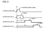
Fig. 9 is a fist timing chart showing a synchronization signal from the communication unit and a reply signal from the distributed unit; and -
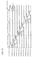
Fig. 10 is a second timing chart showing a synchronization signal from the communication unit and a reply signal from the distributed unit. - An embodiment of the present invention is described below with reference to the drawings. In the following description, the same reference numeral is assigned to the same component. The component having the same reference numeral has the same name and function. Therefore, the description thereof is not repeated in details.
- With reference to
Fig. 1 , aphotoelectric sensor system 1 will be described as an example of a sensor system. However, a sensor system other than a photoelectric sensor system may be used. Thephotoelectric sensor system 1 includes acommunication unit 10, a plurality of distributed units 20 (20A, 20B), and a plurality of sensors 30 (30A-30N). - The
communication unit 10 is connected to aPLC 2 through a network such as a LAN (Local Area Network). As an example, thecommunication unit 10 is configured to communicate with thePLC 2 by using EtherCAT (registered trademark), CC-LINK (registered trademark), DeviceNET, and CompoNET, and the like. - The
distributed units communication unit 10 in parallel to each other. In other words, thedistributed units communication unit 10 in a bus type arrangement. In this embodiment, the twodistributed units - In this embodiment, the distributed
units communication unit 10 in serial communication. That is to say, the distributedunits communication unit 10 through a serial transmission line. Parallel communication may be used instead of or in addition to the serial communication. In other words, the distributedunits communication unit 10 through a parallel transmission line. - In this embodiment, the
communication unit 10 has a function of a master unit, and the distributedunits communication unit 10 is activated, thecommunication unit 10 checks whether the distributedunits communication unit 10, thecommunication unit 10 periodically checks, in order to detect the activation of the distributed units, whether the distributedunits - To each of the
communication unit 10 and the distributedunits different sensors 30. That is to say, thesensors 30A-30N are provided to thephotoelectric sensor system 1 in a distributed manner. As an example, in this embodiment, thesensors 30A-30F are connected physically and electrically to thecommunication unit 10. Thesensors 30G-30I are connected physically and electrically to the distributedunit 20A. Thesensor sensors 30J-30N are connected physically and electrically to the distributedunit 20B. It should be noted that the total number of thesensors 30 and the numbers of thesensors 30 connected to each of thecommunication unit 10 and the distributedunits 20 are not limited to those numbers shown inFig. 1 . For example, no sensor may be connected to thecommunication unit 10. - In this embodiment , the
communication unit 10 stores information received from each of thesensors 30A-30F in a memory and sends the stored information to thePLC 2. The distributedunit 20A stores information received from each of thesensors 30G-30I in a memory and sends the stored information to thecommunication unit 10, and thecommunication unit 10 transmits the signal from the distributedunit 20A to thePLC 2. The distributedunit 20B stores information received from each of thesensors 30J-30N in a memory and sends the stored information to thecommunication unit 10, and thecommunication unit 10 transmits the signal from the distributedunit 20B to thePLC 2. As a result, the signals from thesensors 30A-30N are unified and transmitted to thePLC 2 by thecommunication unit 10. - For example, between the
communication unit 10 and eachsensor 30, a sensor discrimination signal and detected information of eachsensor 30 are transmitted. The sensor discrimination signal is an ON signal or an OFF signal for indicating whether asensor 30 is active or inactive. For example, when asensor 30 is active, the sensor discrimination signal thereof indicates ON. To the contrary, when asensor 30 is inactive, the sensor discrimination signal indicates OFF. In this embodiment using the photoelectric system, the detected information of asensor 30 is, for example, a received light amount, a threshold value, and the like. - In a similar way, between each distributed
unit 20 and eachsensor 30, the sensor discrimination signal and the detected information of eachsensor 30 are transmitted. Further, between thecommunication unit 10 and each distributedunit 20, the sensor discrimination signal and the detected information of eachsensor 30 are transmitted. Further, between thePLC 2 and thecommunication unit 10, the sensor discrimination signal and the detected information of eachsensor 30 are transmitted. - When a signal is transmitted from the
communication unit 10 to one of the distributedunits 20, the one of the distributedunits 20 directly receives the signal from thecommunication unit 10 without other distributed unit. That is, when the distributedunit 20A receives a signal from thecommunication unit 10, the distributedunit 20B does not perform processing to the signal. In the same way, when the distributedunit 20B receives a signal from thecommunication unit 10, the distributedunit 20A does not perform processing to the signal. - It should be noted that an embodiment in which each distributed
unit 20 and thecommunication unit 10 communicate directly to each other includes an embodiment in which, while a communication line connecting one of the distributed units and thecommunication unit 10 physically passes through another one of the distributed units, the another one of the distributed units does not perform processing to the communication between the one of the distributed units and thecommunication unit 10. That is to say, an embodiment in which, while a communication line connecting one of the distributed units and thecommunication unit 10 physically passes through another one of the distributed units, the another one of the distributed units does not perform processing to the communication between the one of the distributed units and thecommunication unit 10 is one of embodiments in which the distributedunits 20 are connected in parallel (connected in a bus type arrangement) to thecommunication unit 10. - With reference to
Figs. 2 and3 , thecommunication unit 10 will be further described. As shown inFig. 2 , thecommunication unit 10 includes aninput connector 101 and anoutput connector 102 used for connection to thePLC 2, aconnector 104 used for connection to the distributedunit 20, aconnector 106 used for connection to thesensor 30, and apower input connector 108. - As shown in
Fig. 3 , thecommunication unit 10 further includes an MPU (Micro Processing Unit) 110, a communication ASIC (Application Specific Integrated Circuit) 112, aserial communication circuit 114, aparallel communication circuit 116, aserial communication circuit 118, and apower supply circuit 120. - The
MPU 110 operates to integrally perform all processing on thecommunication unit 10. Thecommunication ASIC 112 manages communication with thePLC 2. As described above, thecommunication unit 10 communicates with the PLC2 by using EtherCAT, CC-LINK, DeviceNET, CompoNET, and the like. - On the other hand, the
communication unit 10 and the distributedunits communication unit 10 and the distributedunits 20, serial communication is used. Here, parallel communication may be used. For the communication between thecommunication unit 10 and the distributedunit 20, for example, two communication lines are used, one for transmitting and the other for receiving. - The
sensor 30 is mounted on, for example, a side surface of thecommunication unit 10. For the communication between thecommunication unit 10 and thesensor 30, parallel communication or serial communication is used. In other words, thecommunication unit 10 and thesensor 30 are physically connected to each other through a serial transmission line and a parallel transmission line. It should be noted that thecommunication unit 10 and thesensor 30 may be connected through one of a serial transmission line and a parallel transmission line. - With reference to
Figs. 4 and5 , the distributedunit 20 will be further described. As shown inFig. 4 , the distributedunit 20 includes aconnector 202 used for connection to thecommunication unit 10, aconnector 204 used for connection to thesensor 30, apower input connector 206, and arotary switch 208. - As shown in
Fig. 5 , the distributedunit 20 further includes anMPU 210, aserial communication circuit 212 for communication with thecommunication unit 10, aserial communication circuit 214 for communication with thesensor 30, and apower supply circuit 216. - The
MPU 210 operates to integrally perform all processing on the distributedunit 20. As described above, thecommunication unit 10 and the distributedunit 20 are connected to each other in a bus type arrangement, and serial communication is used. - The
sensor 30 is mounted on, for example, a side surface of the distributedunit 20. For the communication between the distributedunit 20 and thesensor 30, serial communication is used, but parallel communication may be used. On the other hand, the distributedunit 20 and thesensor 30 are physically connected to each other through at least one of a serial transmission line and a parallel transmission line. The distributedunit 20 and thesensor 30 may be connected through a serial transmission line and a parallel transmission line. - In this embodiment, since the plurality of the distributed
units 20 are provided in thephotoelectric sensor system 1, for thecommunication unit 10 to communicate with each distributedunit 20 separately, an identification number of each distributedunit 20 needs to be identified. For this purpose, a user can set the identification number for each distributedunit 20 by using therotary switch 208. Thecommunication unit 10 can identify the distributedunit 20 of the transmission source of the received data, on the basis of the identification number included in the received data. In addition, if data to be transmitted from thecommunication unit 10 is configured to have an identification number, a command can be given to a desired distributedunit 20. - With reference to
Fig. 6 , thesensor 30 is further described. Thesensor 30 includes anamplifier unit 301 and afiber unit 302. Theamplifier unit 301 includes an openable cover rotatably fixed to a body case of theamplifier unit 301 and a frame contained in the body case. Theamplifier unit 301 includes a display and an operation unit on the upper surface of the frame which is exposed when the openable cover is open. - On the both sidewalls of the
amplifier unit 301,connector communication unit 10, the distributedunit 20, or anotheramplifier unit 301. Thus, the plurality of theamplifier units 301 can be serially connected to thecommunication unit 10 or the distributedunit 20. As a result, a signal from oneamplifier unit 301 which is connected to anotheramplifier unit 301 is transmitted to thecommunication unit 10 or the distributedunit 20 through the anotheramplifier unit 301. - The
fiber unit 302 is connected to the front wall of theamplifier unit 301. Thefiber unit 302 includes a head, a projecting-side optical fiber, and a receiving-side optical fiber. - With reference to
Fig. 7 , a description is made on a process performed by thecommunication unit 10 to check whether the distributedunit 20 is active according to the embodiment. - When the
communication unit 10 is activated, an activation-checking communication command is sent to the distributedunit 20 at Step (hereinafter, abbreviated as S) 100. The activation-checking communication command is sequentially sent to each distributedunit 20. It should be noted that the number of the distributedunit 20 included in thephotoelectric sensor system 1 and their identification numbers are previously registered at thecommunication unit 10 or thePLC 2 by using a personal computer and the like. - In this embodiment, the distributed
unit 20 is configured to send back the identification number to thecommunication unit 10 upon receiving the activation-checking communication command from thecommunication unit 10. Thus, thecommunication unit 10 can identify an active distributedunit 20 from the identification number received after sending the activation-checking communication command. - Then, at S102, the
communication unit 10 stores, as the identification number of the active distributedunit 20, the identification number of the distributedunit 20 which has sent back the identification number. Upon completion of checking for activation with respect to all the distributed units 20 (S104: YES), thecommunication unit 10 starts communication with the active distributedunits 20 at S106. - When there is an inactive distributed unit 20 (S108: YES), the activation-checking communication command is sent again at S100 after a lapse of a predetermined period (S110: YES). On the other hand, when all the distributed
unit 20 are activated (S108: NO), this process ends. - Instead of the process shown in
Fig. 7 , the process may be performed which is described below with reference toFig. 8 . - When the
communication unit 10 is activated, an activation-checking communication command is sent to the distributedunit 20 having theidentification number 1 at S200. Whencommunication unit 10 is received "1" as identification number from the distributed unit 20 (S202: YES), thecommunication unit 10 stores the receivedidentification number 1 as the identification number N of the active distributedunit 20 at S204. - Then at S206, the
communication unit 10 communicates with the active distributedunit 20. After a lapse of a predetermined time since previously sending the activation-checking communication command (S208: YES), the activation-checking communication command is sent to the distributedunit 20 having the identification number N+1 at S210. - When the
communication unit 10 is received "N+1" as the identification number from the distributed unit 20 (S212: YES), thecommunication unit 10 increments the identification number N of the active distributedunit 20 by 1 at S214. In short, the received identification number N+1 is stored as the identification number N of the active distributedunit 20. In this way, activation is checked in order from the distributedunit 20 having theidentification number 1. - With reference to
Fig. 9 , a description is made on a synchronization signal (command) sent from thecommunication unit 10 to each distributedunit 20 and a signal (command) sent from each distributedunit 20 to thecommunication unit 10 on response to the synchronization signal. With reference toFig. 9 , a description is made on an example in which three distributedunits 20 to which theidentification numbers 1 to 3 are assigned, respectively are provided. - In this embodiment, the
communication unit 10 sends the synchronization signal to all the distributed units at a predetermined time, for example, at a predetermined cycle. Each distributedunit 20, upon receiving the synchronization signal, sends back a signal indicating a detection result of thesensor 30 in a predetermined order. For example, each distributedunit 20 determines when to send back the signal, from the identification number. In this embodiment, the signal is sent back the identification number of the distributedunit 20 in ascending order. Assuming that the identification number of the distributedunit 20 is N and a predetermined constant is α, the waiting time TW from the receiving of the synchronization signal to the sending back of the signal is calculated by the following equation;
unit 20 to send back the signal is used. - In this way, the distributed
units 20 sends back the signals at different times in order; thus, the signals can be efficiently sent from the plurality of the distributedunits 20 connected in parallel to each other to thecommunication unit 10. - With reference to
Fig. 10 , a description is made on an example in which nine distributedunits 20 to which theidentification numbers 1 to 9 are assigned, respectively are provided. - In an example shown in
Fig. 10 , thecommunication unit 10 sends the synchronization signals to the distributedunits 20 at a predetermined cycle (for example, 100 µs). For example, thecommunication unit 10 send the synchronization signals to the three distributedunits 20 to which theidentification numbers 1 to 3 are assigned, respectively, and thecommunication unit 10 then sends the synchronization signals to the three distributedunits 20 to which theidentification numbers 4 to 6 are assigned, respectively. In addition, thecommunication unit 10 then sends the synchronization signals to the three distributedunits 20 to which theidentification numbers 7 to 9 are assigned, respectively. - Accordingly, the three distributed
units 20, to which theidentification numbers 1 to 3 are assigned, respectively, each send back the signal in order after receiving the first synchronization signal. - The three distributed
units 20, to which theidentification numbers 4 to 6 are assigned, respectively, each send back the signal in order after receiving the second synchronization signal. - The three distributed
units 20, to which theidentification numbers 7 to 9 are assigned, respectively, each send back the signal in order after receiving the third synchronization signal. - As a result, in order to get reply signals from all the distributed
units 20, the synchronization signals are sent three times per one cycle. The number of times that the synchronization signals are sent is not limited to 3 and may be changed depending on the number of the distributedunits 20 and the time TR that the distributedunit 20 takes to send the signal. -
Fig. 10 shows an example in which the RS-422 protocol is used for the serial communication. When the RS-485 protocol is used for the serial communication, the signal is sent back from the distributedunit 20 after thecommunication unit 10 completes to send the synchronization signal. That is to say, the time for sending the synchronization signal and the time for sending back the signal from the distributedunit 20 do not overlap. - As described above, in this embodiment, since the
communication unit 10 and the plurality of distributedunits 20 are each connected todifferent sensors 30, thephotoelectric sensor system 1 can include anadditional sensor 30 by additionally installing another distributedunit 20. The plurality of distributedunits 20 are connected to thecommunication unit 10 in a bus type arrangement, and even when the distributedunit 20 is additionally installed, the communication between thecommunication unit 10 and the additionally installed distributedunit 20 can be established without the existing distributedunits 20 relaying the communication. Therefore, the increase in the transmission time of a signal associated with the additional installation of thesensor 30 can be controlled. - It should be understood that the embodiments disclosed herein are illustrative and non-restrictive in every respect. The scope of the present invention is defined by the claims, rather than the description above, and is intended to include any modification within the scope and meaning equivalent to the claims.
Claims (10)
- A sensor system (1) comprising:a master communication device (10) connectable to a control device (2) and a plurality of sensors (30A-30F), the master communication device (10) being configured to store information received from each sensor (30A-30F) in a memory and send the stored information to the control device (2); anda plurality of slave communication devices (20A, 20B) connectable to a plurality of sensors (30G-30N), each of the slave communication devices (20A, 20B) configured to store information received from the respective sensors in a memory and send the stored information to the master communication device (10),wherein the plurality of slave communication devices (20A, 20B) are connected to the master communication device (10) in a bus type arrangement;wherein a sensor discrimination signal and detected information of the sensors (30G-30N) are transmitted between each slave communication device (20A, 20B) and the sensors (30G-30N);wherein the sensor discrimination signal and the detected information are transmitted between the master communication device (10) and each slave communication device (20A, 20B); andwherein the sensor discrimination signal and the detected information are transmitted between the control device (2) and the master communication device (10).
- The sensor system (1) according to claim 1, wherein
the plurality of slave communication devices (20A, 20B) are connected to the master communication device (10) by a serial transmission line. - The sensor system (1) according to claim 1 or 2, wherein
the master communication device (10) and the plurality of slave communication devices (20A, 20B) are connected to the sensors (30A-30N) by a serial transmission line and a parallel transmission line. - The sensor system (1) according to any of claims 1 to 3, wherein
the plurality of slave communication devices (20A, 20B) are connected to the sensors (30G-30N) at least by one of a serial transmission line and a parallel transmission line. - The sensor system (1) according to any of claims 1 to 4, wherein
the master communication device (10) comprises a checking section configured to periodically check whether the slave communication device (20A, 20B) is activated, and configured to communicate with the slave communication device (20A, 20B) which is activated. - The sensor system (1) according to claim 5, wherein
the checking section comprises:a transmission section configured to send an activation-checking communication command to the slave communication device (20A, 20B);a storing section configured to store an identification of the slave communication devices (20A, 20B) which are activated; anda periodical-check section configured to periodically send the activation-checking communication command. - The sensor system (1) according to claim 1, wherein
each of the plurality of slave communication devices (20A, 20B) comprises a signal sending section configured to, upon receiving a command from the master communication device (10), send a signal to the master communication device (10) in an order previously registered at the slave communication device (20A, 20B). - The sensor system (1) according to claim 7, wherein
the master communication device (10) comprises a synchronization signal sending section configured to send a synchronization signal to the plurality of slave communication devices (20A, 20B). - The sensor system (1) according to claim 7 or 8, wherein the signal sending section is configured to send the signal to the master communication device (10) after a lapse of a waiting time calculated based on the order previously registered at the slave communication device (20A, 20B).
- A communication device (10) connectable to a control device (2) and a plurality of sensors (30A-30F), the communication device (10) storing information received from each sensor (30A-30F) in a memory and sending the information stored in the memory to the control device (2), the communication device (10) comprising:a first communication unit configured to communicate with the sensors (30A-30F);a second communication unit configured to communicate with the control device (2); anda third communication unit configured to communicate with a plurality of slave communication units (20A, 20B), the plurality of slave communication units (20A, 20B) physically and electrically connectable to a plurality of sensors which are different from the sensors connected to the communication device (10), each of the slave communication units (20A, 20B) storing information received from each sensor (30G-30N) in a memory and sending the information stored in the memory to the communication device (10), and being connected to the communication device (10) in a bus type arrangement.
Applications Claiming Priority (1)
| Application Number | Priority Date | Filing Date | Title |
|---|---|---|---|
| JP2012234200A JP6098106B2 (en) | 2012-10-23 | 2012-10-23 | Sensor system and communication device |
Publications (2)
| Publication Number | Publication Date |
|---|---|
| EP2725748A2 true EP2725748A2 (en) | 2014-04-30 |
| EP2725748A3 EP2725748A3 (en) | 2015-03-11 |
Family
ID=49226061
Family Applications (1)
| Application Number | Title | Priority Date | Filing Date |
|---|---|---|---|
| EP13185523.1A Withdrawn EP2725748A3 (en) | 2012-10-23 | 2013-09-23 | Sensor system and communication device |
Country Status (2)
| Country | Link |
|---|---|
| EP (1) | EP2725748A3 (en) |
| JP (1) | JP6098106B2 (en) |
Cited By (1)
| Publication number | Priority date | Publication date | Assignee | Title |
|---|---|---|---|---|
| EP3211829A1 (en) * | 2016-02-26 | 2017-08-30 | Omron Corporation | Master device, slave device, error monitoring system, and control method and control program of master device |
Families Citing this family (3)
| Publication number | Priority date | Publication date | Assignee | Title |
|---|---|---|---|---|
| JP7340322B2 (en) | 2017-06-13 | 2023-09-07 | 株式会社キーエンス | Confocal displacement measurement system |
| JP7189499B2 (en) | 2018-05-07 | 2022-12-14 | オムロン株式会社 | sensor system |
| JP7137761B2 (en) * | 2019-03-06 | 2022-09-15 | オムロン株式会社 | sensor system |
Citations (2)
| Publication number | Priority date | Publication date | Assignee | Title |
|---|---|---|---|---|
| JP3852067B2 (en) | 1999-06-08 | 2006-11-29 | 株式会社山武 | Communications system |
| JP4294985B2 (en) | 2003-03-26 | 2009-07-15 | 株式会社キーエンス | Continuous sensor system, master unit, sensor unit and sensor relay unit |
Family Cites Families (12)
| Publication number | Priority date | Publication date | Assignee | Title |
|---|---|---|---|---|
| DE4322249A1 (en) * | 1992-10-23 | 1994-04-28 | Marquardt Gmbh | Bus switch |
| JP3293090B2 (en) * | 1995-11-06 | 2002-06-17 | オムロン株式会社 | PLC remote I/O system, execution method of PLC remote I/O system, and PLC main body in PLC remote I/O system |
| JP2002278787A (en) * | 2001-03-22 | 2002-09-27 | Nec Corp | System for controlling master/slave dynamic configuration |
| FR2837296B1 (en) * | 2002-03-15 | 2004-06-25 | Airbus France | DEVICE AND METHOD FOR ACQUIRING MEASUREMENTS USING A DIGITAL COMMUNICATION BUS, USED IN PARTICULAR DURING TESTS OF AN AIRCRAFT |
| US7181557B1 (en) * | 2003-09-15 | 2007-02-20 | National Semiconductor Corporation | Single wire bus for connecting devices and methods of operating the same |
| JP2006062516A (en) * | 2004-08-26 | 2006-03-09 | Pacific Ind Co Ltd | Tire condition monitoring device, transmission device, and receiving device |
| JP4919702B2 (en) * | 2006-05-23 | 2012-04-18 | 株式会社キーエンス | Sensor device and sensor system |
| WO2008078585A1 (en) * | 2006-12-27 | 2008-07-03 | Kabushiki Kaisha Yaskawa Denki | Master slave communication system and master slave communication method |
| JP2008252882A (en) * | 2007-03-05 | 2008-10-16 | Yaskawa Electric Corp | Serial communication device for sensor and serial communication method |
| JP4999006B2 (en) * | 2008-04-21 | 2012-08-15 | 独立行政法人産業技術総合研究所 | Serial bus transmission system |
| JP5567829B2 (en) * | 2009-12-01 | 2014-08-06 | 株式会社メガチップス | Sensor device and semiconductor device |
| US10138901B2 (en) * | 2011-03-21 | 2018-11-27 | Nortek Air Solutions, Llc | Systems and methods for implementing a fan array with quick connect and modular control |
-
2012
- 2012-10-23 JP JP2012234200A patent/JP6098106B2/en not_active Expired - Fee Related
-
2013
- 2013-09-23 EP EP13185523.1A patent/EP2725748A3/en not_active Withdrawn
Patent Citations (2)
| Publication number | Priority date | Publication date | Assignee | Title |
|---|---|---|---|---|
| JP3852067B2 (en) | 1999-06-08 | 2006-11-29 | 株式会社山武 | Communications system |
| JP4294985B2 (en) | 2003-03-26 | 2009-07-15 | 株式会社キーエンス | Continuous sensor system, master unit, sensor unit and sensor relay unit |
Cited By (4)
| Publication number | Priority date | Publication date | Assignee | Title |
|---|---|---|---|---|
| EP3211829A1 (en) * | 2016-02-26 | 2017-08-30 | Omron Corporation | Master device, slave device, error monitoring system, and control method and control program of master device |
| CN107132833A (en) * | 2016-02-26 | 2017-09-05 | 欧姆龙株式会社 | Main frame, slave device and its control method, control program, error monitoring system |
| US10554522B2 (en) | 2016-02-26 | 2020-02-04 | Omron Corporation | Master device, slave device, error monitoring system, and control method and control program of master device |
| CN107132833B (en) * | 2016-02-26 | 2020-09-29 | 欧姆龙株式会社 | Master device, slave device, control method thereof, recording medium, and error monitoring system |
Also Published As
| Publication number | Publication date |
|---|---|
| JP2014085833A (en) | 2014-05-12 |
| JP6098106B2 (en) | 2017-03-22 |
| EP2725748A3 (en) | 2015-03-11 |
Similar Documents
| Publication | Publication Date | Title |
|---|---|---|
| US4628437A (en) | Telecontrol system | |
| JP3477709B2 (en) | Sensor system | |
| EP2725748A2 (en) | Sensor system and communication device | |
| US10583984B2 (en) | Dynamic storage rack unit for providing material in logistics and manufacturing processes | |
| EP2725436A1 (en) | Communication device connectable to a control device and a plurality of sensors | |
| CN104144094B (en) | Digital bus system slave node and its operating method | |
| WO2015007528A1 (en) | System of devices | |
| EP1760563B1 (en) | Communication system with master, slave and repeater units | |
| EP2730984A2 (en) | Sensor system | |
| KR101932892B1 (en) | Multi leak and fire sensing apparatus | |
| JP2000196700A (en) | Start-stop synchronization data transmitting method | |
| KR102639652B1 (en) | Conveyor devices with sensors using bus data encoding | |
| EP2782356B1 (en) | Fault detection method and substation terminal used for said method | |
| GB2433634A (en) | Alarm system for monitoring HVAC ducts to detect smoke | |
| US20230026273A1 (en) | Status signal output | |
| US20040199352A1 (en) | Method of judging communication stability of network system and master unit, slave and repeater therefor | |
| JP2014096698A (en) | Communication device | |
| CN106254196A (en) | CAN safety monitoring method | |
| EP1775686B1 (en) | Occupation monitoring system | |
| KR100473974B1 (en) | Air press control system using the bluetooth rf module | |
| US6772373B2 (en) | Disorder detecting device | |
| JP7068654B2 (en) | Sensor system | |
| JP2002334390A (en) | Connected sensor system | |
| KR20080076530A (en) | SOY Implementation Method of Monitoring and Control System | |
| EP2782357A1 (en) | Input signal abnormality detection method and substation terminal used for method |
Legal Events
| Date | Code | Title | Description |
|---|---|---|---|
| PUAI | Public reference made under article 153(3) epc to a published international application that has entered the european phase |
Free format text: ORIGINAL CODE: 0009012 |
|
| 17P | Request for examination filed |
Effective date: 20130923 |
|
| AK | Designated contracting states |
Kind code of ref document: A2 Designated state(s): AL AT BE BG CH CY CZ DE DK EE ES FI FR GB GR HR HU IE IS IT LI LT LU LV MC MK MT NL NO PL PT RO RS SE SI SK SM TR |
|
| AX | Request for extension of the european patent |
Extension state: BA ME |
|
| PUAL | Search report despatched |
Free format text: ORIGINAL CODE: 0009013 |
|
| AK | Designated contracting states |
Kind code of ref document: A3 Designated state(s): AL AT BE BG CH CY CZ DE DK EE ES FI FR GB GR HR HU IE IS IT LI LT LU LV MC MK MT NL NO PL PT RO RS SE SI SK SM TR |
|
| AX | Request for extension of the european patent |
Extension state: BA ME |
|
| RIC1 | Information provided on ipc code assigned before grant |
Ipc: H04J 3/16 20060101ALI20150203BHEP Ipc: H04L 12/413 20060101ALI20150203BHEP Ipc: H04L 12/26 20060101ALI20150203BHEP Ipc: H04L 12/64 20060101ALI20150203BHEP Ipc: H04W 4/00 20090101ALI20150203BHEP Ipc: H04L 29/08 20060101ALI20150203BHEP Ipc: G05B 19/00 20060101ALI20150203BHEP Ipc: G05B 23/02 20060101ALI20150203BHEP Ipc: H04L 12/403 20060101AFI20150203BHEP Ipc: G05B 19/042 20060101ALI20150203BHEP |
|
| 17Q | First examination report despatched |
Effective date: 20160509 |
|
| STAA | Information on the status of an ep patent application or granted ep patent |
Free format text: STATUS: EXAMINATION IS IN PROGRESS |
|
| STAA | Information on the status of an ep patent application or granted ep patent |
Free format text: STATUS: THE APPLICATION IS DEEMED TO BE WITHDRAWN |
|
| 18D | Application deemed to be withdrawn |
Effective date: 20170907 |