EP2725625A1 - Rear surface protective sheet for solar cell - Google Patents
Rear surface protective sheet for solar cell Download PDFInfo
- Publication number
- EP2725625A1 EP2725625A1 EP12803488.1A EP12803488A EP2725625A1 EP 2725625 A1 EP2725625 A1 EP 2725625A1 EP 12803488 A EP12803488 A EP 12803488A EP 2725625 A1 EP2725625 A1 EP 2725625A1
- Authority
- EP
- European Patent Office
- Prior art keywords
- heat conversion
- heat
- layer
- surface protective
- protective sheet
- Prior art date
- Legal status (The legal status is an assumption and is not a legal conclusion. Google has not performed a legal analysis and makes no representation as to the accuracy of the status listed.)
- Withdrawn
Links
- 230000001681 protective effect Effects 0.000 title claims abstract description 55
- 238000006243 chemical reaction Methods 0.000 claims abstract description 96
- 239000000945 filler Substances 0.000 claims abstract description 34
- 239000010410 layer Substances 0.000 claims description 96
- 229920005989 resin Polymers 0.000 claims description 32
- 239000011347 resin Substances 0.000 claims description 32
- 239000000758 substrate Substances 0.000 claims description 32
- 239000012793 heat-sealing layer Substances 0.000 claims description 23
- 239000011248 coating agent Substances 0.000 claims description 13
- 238000000576 coating method Methods 0.000 claims description 13
- 239000000463 material Substances 0.000 claims description 13
- 238000001035 drying Methods 0.000 claims description 3
- VGGSQFUCUMXWEO-UHFFFAOYSA-N Ethene Chemical compound C=C VGGSQFUCUMXWEO-UHFFFAOYSA-N 0.000 claims description 2
- 239000005977 Ethylene Substances 0.000 claims description 2
- 229920006163 vinyl copolymer Polymers 0.000 claims description 2
- 239000012790 adhesive layer Substances 0.000 description 15
- 230000000052 comparative effect Effects 0.000 description 15
- 239000005038 ethylene vinyl acetate Substances 0.000 description 15
- 229920001200 poly(ethylene-vinyl acetate) Polymers 0.000 description 15
- 239000003973 paint Substances 0.000 description 11
- -1 polyethylene terephthalate Polymers 0.000 description 11
- 239000006096 absorbing agent Substances 0.000 description 10
- 239000000853 adhesive Substances 0.000 description 10
- 230000001070 adhesive effect Effects 0.000 description 10
- 230000007423 decrease Effects 0.000 description 7
- 230000000694 effects Effects 0.000 description 6
- 238000009413 insulation Methods 0.000 description 6
- 239000012939 laminating adhesive Substances 0.000 description 6
- 229920002620 polyvinyl fluoride Polymers 0.000 description 6
- JOYRKODLDBILNP-UHFFFAOYSA-N Ethyl urethane Chemical compound CCOC(N)=O JOYRKODLDBILNP-UHFFFAOYSA-N 0.000 description 5
- 238000000034 method Methods 0.000 description 5
- 239000005020 polyethylene terephthalate Substances 0.000 description 5
- 229920000139 polyethylene terephthalate Polymers 0.000 description 5
- 239000003566 sealing material Substances 0.000 description 5
- 239000004952 Polyamide Substances 0.000 description 4
- 238000010521 absorption reaction Methods 0.000 description 4
- XAGFODPZIPBFFR-UHFFFAOYSA-N aluminium Chemical compound [Al] XAGFODPZIPBFFR-UHFFFAOYSA-N 0.000 description 4
- 238000009820 dry lamination Methods 0.000 description 4
- 239000011888 foil Substances 0.000 description 4
- 239000011521 glass Substances 0.000 description 4
- 230000017525 heat dissipation Effects 0.000 description 4
- 229920000092 linear low density polyethylene Polymers 0.000 description 4
- 239000004707 linear low-density polyethylene Substances 0.000 description 4
- 239000012528 membrane Substances 0.000 description 4
- 239000000203 mixture Substances 0.000 description 4
- 229920002647 polyamide Polymers 0.000 description 4
- 229920006267 polyester film Polymers 0.000 description 4
- 229920001721 polyimide Polymers 0.000 description 4
- 229920001955 polyphenylene ether Polymers 0.000 description 4
- 229920002635 polyurethane Polymers 0.000 description 4
- 239000004814 polyurethane Substances 0.000 description 4
- 230000005855 radiation Effects 0.000 description 4
- RTTZISZSHSCFRH-UHFFFAOYSA-N 1,3-bis(isocyanatomethyl)benzene Chemical compound O=C=NCC1=CC=CC(CN=C=O)=C1 RTTZISZSHSCFRH-UHFFFAOYSA-N 0.000 description 3
- 239000004642 Polyimide Substances 0.000 description 3
- VYPSYNLAJGMNEJ-UHFFFAOYSA-N Silicium dioxide Chemical compound O=[Si]=O VYPSYNLAJGMNEJ-UHFFFAOYSA-N 0.000 description 3
- 229910052782 aluminium Inorganic materials 0.000 description 3
- 230000005540 biological transmission Effects 0.000 description 3
- 239000003795 chemical substances by application Substances 0.000 description 3
- 239000011231 conductive filler Substances 0.000 description 3
- 239000003595 mist Substances 0.000 description 3
- 239000002245 particle Substances 0.000 description 3
- 239000007787 solid Substances 0.000 description 3
- 239000000126 substance Substances 0.000 description 3
- 238000004383 yellowing Methods 0.000 description 3
- VTYYLEPIZMXCLO-UHFFFAOYSA-L Calcium carbonate Chemical compound [Ca+2].[O-]C([O-])=O VTYYLEPIZMXCLO-UHFFFAOYSA-L 0.000 description 2
- OKTJSMMVPCPJKN-UHFFFAOYSA-N Carbon Chemical compound [C] OKTJSMMVPCPJKN-UHFFFAOYSA-N 0.000 description 2
- YCKRFDGAMUMZLT-UHFFFAOYSA-N Fluorine atom Chemical compound [F] YCKRFDGAMUMZLT-UHFFFAOYSA-N 0.000 description 2
- UQSXHKLRYXJYBZ-UHFFFAOYSA-N Iron oxide Chemical compound [Fe]=O UQSXHKLRYXJYBZ-UHFFFAOYSA-N 0.000 description 2
- 229920000106 Liquid crystal polymer Polymers 0.000 description 2
- 239000004977 Liquid-crystal polymers (LCPs) Substances 0.000 description 2
- 239000002033 PVDF binder Substances 0.000 description 2
- 239000004696 Poly ether ether ketone Substances 0.000 description 2
- 239000004697 Polyetherimide Substances 0.000 description 2
- 239000004734 Polyphenylene sulfide Substances 0.000 description 2
- 239000004743 Polypropylene Substances 0.000 description 2
- 229920010524 Syndiotactic polystyrene Polymers 0.000 description 2
- GWEVSGVZZGPLCZ-UHFFFAOYSA-N Titan oxide Chemical compound O=[Ti]=O GWEVSGVZZGPLCZ-UHFFFAOYSA-N 0.000 description 2
- 239000004699 Ultra-high molecular weight polyethylene Substances 0.000 description 2
- XLOMVQKBTHCTTD-UHFFFAOYSA-N Zinc monoxide Chemical compound [Zn]=O XLOMVQKBTHCTTD-UHFFFAOYSA-N 0.000 description 2
- 230000015572 biosynthetic process Effects 0.000 description 2
- 229910052799 carbon Inorganic materials 0.000 description 2
- 229920006351 engineering plastic Polymers 0.000 description 2
- 229920000840 ethylene tetrafluoroethylene copolymer Polymers 0.000 description 2
- 239000011737 fluorine Substances 0.000 description 2
- 229910052731 fluorine Inorganic materials 0.000 description 2
- 238000010438 heat treatment Methods 0.000 description 2
- RRAMGCGOFNQTLD-UHFFFAOYSA-N hexamethylene diisocyanate Chemical compound O=C=NCCCCCCN=C=O RRAMGCGOFNQTLD-UHFFFAOYSA-N 0.000 description 2
- TWNQGVIAIRXVLR-UHFFFAOYSA-N oxo(oxoalumanyloxy)alumane Chemical compound O=[Al]O[Al]=O TWNQGVIAIRXVLR-UHFFFAOYSA-N 0.000 description 2
- 229920002492 poly(sulfone) Polymers 0.000 description 2
- 229920001230 polyarylate Polymers 0.000 description 2
- 229920001707 polybutylene terephthalate Polymers 0.000 description 2
- 239000004417 polycarbonate Substances 0.000 description 2
- 229920000515 polycarbonate Polymers 0.000 description 2
- 229920002530 polyetherether ketone Polymers 0.000 description 2
- 229920001601 polyetherimide Polymers 0.000 description 2
- 239000011112 polyethylene naphthalate Substances 0.000 description 2
- 229920005862 polyol Polymers 0.000 description 2
- 229920006324 polyoxymethylene Polymers 0.000 description 2
- 229920000069 polyphenylene sulfide Polymers 0.000 description 2
- 229920001155 polypropylene Polymers 0.000 description 2
- 229920002981 polyvinylidene fluoride Polymers 0.000 description 2
- 239000002356 single layer Substances 0.000 description 2
- 238000005507 spraying Methods 0.000 description 2
- 239000002344 surface layer Substances 0.000 description 2
- OGIDPMRJRNCKJF-UHFFFAOYSA-N titanium oxide Inorganic materials [Ti]=O OGIDPMRJRNCKJF-UHFFFAOYSA-N 0.000 description 2
- 229920000785 ultra high molecular weight polyethylene Polymers 0.000 description 2
- 229910052582 BN Inorganic materials 0.000 description 1
- 229920002799 BoPET Polymers 0.000 description 1
- PZNSFCLAULLKQX-UHFFFAOYSA-N Boron nitride Chemical compound N#B PZNSFCLAULLKQX-UHFFFAOYSA-N 0.000 description 1
- 241000127225 Enceliopsis nudicaulis Species 0.000 description 1
- 239000005057 Hexamethylene diisocyanate Substances 0.000 description 1
- 229920012266 Poly(ether sulfone) PES Polymers 0.000 description 1
- 229930182556 Polyacetal Natural products 0.000 description 1
- 239000004698 Polyethylene Substances 0.000 description 1
- 239000004721 Polyphenylene oxide Substances 0.000 description 1
- 239000004793 Polystyrene Substances 0.000 description 1
- 229910000831 Steel Inorganic materials 0.000 description 1
- 229910000019 calcium carbonate Inorganic materials 0.000 description 1
- 229910000420 cerium oxide Inorganic materials 0.000 description 1
- 229920006026 co-polymeric resin Polymers 0.000 description 1
- 239000011247 coating layer Substances 0.000 description 1
- 238000007739 conversion coating Methods 0.000 description 1
- 229910021419 crystalline silicon Inorganic materials 0.000 description 1
- 230000002708 enhancing effect Effects 0.000 description 1
- 150000002148 esters Chemical class 0.000 description 1
- 230000002349 favourable effect Effects 0.000 description 1
- 230000007062 hydrolysis Effects 0.000 description 1
- 238000006460 hydrolysis reaction Methods 0.000 description 1
- 239000012948 isocyanate Substances 0.000 description 1
- 150000002513 isocyanates Chemical class 0.000 description 1
- 238000010030 laminating Methods 0.000 description 1
- 238000003475 lamination Methods 0.000 description 1
- 230000007774 longterm Effects 0.000 description 1
- 239000000395 magnesium oxide Substances 0.000 description 1
- CPLXHLVBOLITMK-UHFFFAOYSA-N magnesium oxide Inorganic materials [Mg]=O CPLXHLVBOLITMK-UHFFFAOYSA-N 0.000 description 1
- AXZKOIWUVFPNLO-UHFFFAOYSA-N magnesium;oxygen(2-) Chemical compound [O-2].[Mg+2] AXZKOIWUVFPNLO-UHFFFAOYSA-N 0.000 description 1
- 239000011159 matrix material Substances 0.000 description 1
- 229910052751 metal Inorganic materials 0.000 description 1
- 239000002184 metal Substances 0.000 description 1
- 238000005121 nitriding Methods 0.000 description 1
- BMMGVYCKOGBVEV-UHFFFAOYSA-N oxo(oxoceriooxy)cerium Chemical compound [Ce]=O.O=[Ce]=O BMMGVYCKOGBVEV-UHFFFAOYSA-N 0.000 description 1
- RVTZCBVAJQQJTK-UHFFFAOYSA-N oxygen(2-);zirconium(4+) Chemical compound [O-2].[O-2].[Zr+4] RVTZCBVAJQQJTK-UHFFFAOYSA-N 0.000 description 1
- 229920003207 poly(ethylene-2,6-naphthalate) Polymers 0.000 description 1
- 229920003050 poly-cycloolefin Polymers 0.000 description 1
- 229920006289 polycarbonate film Polymers 0.000 description 1
- 229920000728 polyester Polymers 0.000 description 1
- 229920000570 polyether Polymers 0.000 description 1
- 229920000573 polyethylene Polymers 0.000 description 1
- 229920000098 polyolefin Polymers 0.000 description 1
- 150000003077 polyols Chemical class 0.000 description 1
- 229920002223 polystyrene Polymers 0.000 description 1
- 239000004800 polyvinyl chloride Substances 0.000 description 1
- 229920000915 polyvinyl chloride Polymers 0.000 description 1
- 238000007789 sealing Methods 0.000 description 1
- 239000000377 silicon dioxide Substances 0.000 description 1
- 229910052814 silicon oxide Inorganic materials 0.000 description 1
- 239000007921 spray Substances 0.000 description 1
- 239000010959 steel Substances 0.000 description 1
- 238000005728 strengthening Methods 0.000 description 1
- 229920001909 styrene-acrylic polymer Polymers 0.000 description 1
- 229920002803 thermoplastic polyurethane Polymers 0.000 description 1
- 239000011787 zinc oxide Substances 0.000 description 1
- 229910001928 zirconium oxide Inorganic materials 0.000 description 1
Images

Classifications
-
- H—ELECTRICITY
- H10—SEMICONDUCTOR DEVICES; ELECTRIC SOLID-STATE DEVICES NOT OTHERWISE PROVIDED FOR
- H10F—INORGANIC SEMICONDUCTOR DEVICES SENSITIVE TO INFRARED RADIATION, LIGHT, ELECTROMAGNETIC RADIATION OF SHORTER WAVELENGTH OR CORPUSCULAR RADIATION
- H10F19/00—Integrated devices, or assemblies of multiple devices, comprising at least one photovoltaic cell covered by group H10F10/00, e.g. photovoltaic modules
- H10F19/80—Encapsulations or containers for integrated devices, or assemblies of multiple devices, having photovoltaic cells
- H10F19/85—Protective back sheets
-
- B—PERFORMING OPERATIONS; TRANSPORTING
- B32—LAYERED PRODUCTS
- B32B—LAYERED PRODUCTS, i.e. PRODUCTS BUILT-UP OF STRATA OF FLAT OR NON-FLAT, e.g. CELLULAR OR HONEYCOMB, FORM
- B32B17/00—Layered products essentially comprising sheet glass, or glass, slag, or like fibres
- B32B17/06—Layered products essentially comprising sheet glass, or glass, slag, or like fibres comprising glass as the main or only constituent of a layer, next to another layer of a specific material
- B32B17/10—Layered products essentially comprising sheet glass, or glass, slag, or like fibres comprising glass as the main or only constituent of a layer, next to another layer of a specific material of synthetic resin
- B32B17/10005—Layered products essentially comprising sheet glass, or glass, slag, or like fibres comprising glass as the main or only constituent of a layer, next to another layer of a specific material of synthetic resin laminated safety glass or glazing
- B32B17/10009—Layered products essentially comprising sheet glass, or glass, slag, or like fibres comprising glass as the main or only constituent of a layer, next to another layer of a specific material of synthetic resin laminated safety glass or glazing characterized by the number, the constitution or treatment of glass sheets
- B32B17/10018—Layered products essentially comprising sheet glass, or glass, slag, or like fibres comprising glass as the main or only constituent of a layer, next to another layer of a specific material of synthetic resin laminated safety glass or glazing characterized by the number, the constitution or treatment of glass sheets comprising only one glass sheet
-
- H—ELECTRICITY
- H02—GENERATION; CONVERSION OR DISTRIBUTION OF ELECTRIC POWER
- H02S—GENERATION OF ELECTRIC POWER BY CONVERSION OF INFRARED RADIATION, VISIBLE LIGHT OR ULTRAVIOLET LIGHT, e.g. USING PHOTOVOLTAIC [PV] MODULES
- H02S40/00—Components or accessories in combination with PV modules, not provided for in groups H02S10/00 - H02S30/00
- H02S40/40—Thermal components
- H02S40/44—Means to utilise heat energy, e.g. hybrid systems producing warm water and electricity at the same time
-
- H—ELECTRICITY
- H10—SEMICONDUCTOR DEVICES; ELECTRIC SOLID-STATE DEVICES NOT OTHERWISE PROVIDED FOR
- H10F—INORGANIC SEMICONDUCTOR DEVICES SENSITIVE TO INFRARED RADIATION, LIGHT, ELECTROMAGNETIC RADIATION OF SHORTER WAVELENGTH OR CORPUSCULAR RADIATION
- H10F77/00—Constructional details of devices covered by this subclass
- H10F77/60—Arrangements for cooling, heating, ventilating or compensating for temperature fluctuations
- H10F77/63—Arrangements for cooling directly associated or integrated with photovoltaic cells, e.g. heat sinks directly associated with the photovoltaic cells or integrated Peltier elements for active cooling
-
- Y—GENERAL TAGGING OF NEW TECHNOLOGICAL DEVELOPMENTS; GENERAL TAGGING OF CROSS-SECTIONAL TECHNOLOGIES SPANNING OVER SEVERAL SECTIONS OF THE IPC; TECHNICAL SUBJECTS COVERED BY FORMER USPC CROSS-REFERENCE ART COLLECTIONS [XRACs] AND DIGESTS
- Y02—TECHNOLOGIES OR APPLICATIONS FOR MITIGATION OR ADAPTATION AGAINST CLIMATE CHANGE
- Y02B—CLIMATE CHANGE MITIGATION TECHNOLOGIES RELATED TO BUILDINGS, e.g. HOUSING, HOUSE APPLIANCES OR RELATED END-USER APPLICATIONS
- Y02B10/00—Integration of renewable energy sources in buildings
- Y02B10/10—Photovoltaic [PV]
-
- Y—GENERAL TAGGING OF NEW TECHNOLOGICAL DEVELOPMENTS; GENERAL TAGGING OF CROSS-SECTIONAL TECHNOLOGIES SPANNING OVER SEVERAL SECTIONS OF THE IPC; TECHNICAL SUBJECTS COVERED BY FORMER USPC CROSS-REFERENCE ART COLLECTIONS [XRACs] AND DIGESTS
- Y02—TECHNOLOGIES OR APPLICATIONS FOR MITIGATION OR ADAPTATION AGAINST CLIMATE CHANGE
- Y02E—REDUCTION OF GREENHOUSE GAS [GHG] EMISSIONS, RELATED TO ENERGY GENERATION, TRANSMISSION OR DISTRIBUTION
- Y02E10/00—Energy generation through renewable energy sources
- Y02E10/50—Photovoltaic [PV] energy
-
- Y—GENERAL TAGGING OF NEW TECHNOLOGICAL DEVELOPMENTS; GENERAL TAGGING OF CROSS-SECTIONAL TECHNOLOGIES SPANNING OVER SEVERAL SECTIONS OF THE IPC; TECHNICAL SUBJECTS COVERED BY FORMER USPC CROSS-REFERENCE ART COLLECTIONS [XRACs] AND DIGESTS
- Y02—TECHNOLOGIES OR APPLICATIONS FOR MITIGATION OR ADAPTATION AGAINST CLIMATE CHANGE
- Y02E—REDUCTION OF GREENHOUSE GAS [GHG] EMISSIONS, RELATED TO ENERGY GENERATION, TRANSMISSION OR DISTRIBUTION
- Y02E10/00—Energy generation through renewable energy sources
- Y02E10/60—Thermal-PV hybrids
Definitions
- the present invention relates to a rear-surface protective sheet for solar cells that is disposed on the rear-surface of a solar cell, in particular to a rear-surface protective sheet for solar cells that has a function of suppressing temperature increase in a solar cell.
- Solar cells are mainly installed on rooftops of buildings. Because of direct heat from sunlight and heat from the roof, the temperature of the solar cell sometimes reaches 70°C or more. It is said that the conversion efficiency of crystalline silicon-based solar cells decreases by about 0.4%/°C as the temperature increases. Further, a rear-surface protective sheet for solar cells is typically applied on the rear surface of a solar cell, and the resulting laminate is generally referred to as a solar cell module.
- Patent Literature 1 is directed to a heat-releasing membrane for a solar cell module, and a solar cell module including the heat-releasing membrane. Specifically, Patent Literature 1 discloses that providing a coating material layer having heat dissipation (heat-releasing membrane) on the rear surface of a solar cell decreases the module temperature. To provide the coating material layer with weather resistance, an overcoating or a weather-resistant film is required, and a material that does not hinder heat dissipation must be selected.
- Patent Literature 2 is directed to a mist spraying device. Specifically, Patent Literature 2 discloses spraying mist to a solar cell module by a mist spray system using a heat exchange paint to decrease the module temperature.
- the rear-surface protective sheet for solar cells and the solar cell disclosed in Patent Literature 2 do not themselves have a function of suppressing temperature increase.
- the heat exchange paint mentioned above is a coating material containing a heat conversion molecule that has a function of converting thermal energy into vibrational energy to consume the thermal energy.
- This coating material is commercially available from Arbar Industrial Co., Ltd., under the product names of Tough Coat D42, Tough Coat D47, etc., and also referred to as a heat-consuming coating material.
- An object of the present invention is to provide a rear-surface protective sheet for solar cells that has a function of suppressing temperature increase in a solar cell.
- the present inventors conducted extensive research to attain the above object and found that the use of a rear-surface protective sheet for solar cells that has a specific heat conversion layer can attain the above object.
- the present invention was thus accomplished.
- the present invention relates to the following rear-surface protective sheets for solar cells.
- the rear-surface protective sheet for solar cells of the present invention is explained in detail below.
- the rear-surface protective sheet for solar cells of the present invention is disposed on the rear surface of a solar cell.
- the rear-surface protective sheet includes a heat conversion layer containing a heat conversion filler that has a function of converting thermal energy into vibrational energy to consume the thermal energy.
- the heat conversion filler in the heat conversion layer has a density of 3 to 35 g/m 2 .
- the rear-surface protective sheet for solar cells of the present invention can suppress the temperature increase of a solar cell because the heat conversion filler in the heat conversion layer converts thermal energy into vibrational energy to thereby consume the thermal energy. It is desired that a coating film that suppresses temperature increase by using reflection or radiation of thermal energy be formed at the outermost layer; however, since the heat conversion layer used in the present invention can consume heat energy even when it is not formed as the outermost layer, the heat conversion layer of the present invention can be formed as an inner layer (a layer that is not exposed on the surface of the sheet). Further, a material that does not interfere with heat dissipation has been required for forming a weather-resistant film at the outermost layer; however, any of a wide variety of known weather-resistant films can be used in the present invention.
- the known layer structure of a rear-surface protective sheet for solar cells is generally such that a heat-sealing layer (for adhering to the rear surface of a solar cell) is applied on a resin film substrate via an adhesive layer.
- a layer structure in which a weather-resistant film is applied on the other side of the resin film substrate via an adhesive layer is also known.
- the heat conversion layer used in the present invention can be formed at any position as long as it does not hinder the adhesion of the rear surface of the solar cell and the rear-surface protective sheet for solar cells via the heat-sealing layer.
- the rear-surface protective sheet for solar cells of the present invention has, for example, layer structures (a) to (d) shown in Fig. 1 .
- heat-sealing layer 2 is formed on resin film substrate 1 via adhesive layer 3, and heat conversion layer 4 is formed on the other side of resin film substrate 1.
- Layer structure (b) of Fig. 1 is the same as layer structure (a) of Fig. 1 , except that weather-resistant film 5 is formed on the outer side of heat conversion layer 4 via adhesive layer 3. Such a formation of weather-resistant film 5 on the outermost layer can increase the scratch resistance of the rear-surface protective sheet for solar cells, and prevent or suppress damage to the heat conversion layer.
- Layer structure (c) of Fig. 1 is the same as layer structure (b) of Fig. 1 , except that heat conversion layer 4 formed on one side of resin film substrate 1 is formed on both sides of resin film substrate 1. Forming heat conversion layer 4 on only one side of resin film substrate 1 may curl the laminate during the formation of heat conversion layer 4. Such curling can be prevented or suppressed when heat conversion layer 4 is formed on both sides of resin film substrate 1 as in layer structure (c) of Fig. 1 .
- layer 6 is a heat conversion layer and an adhesive layer.
- Layer 6 can be obtained by mixing the heat conversion filler used in the present invention with a composition for forming the adhesive layer in a manner such that the composition has a desired density, and forming a membrane.
- Layer structures (a) to (d) are merely examples, and of course other layer structures can be used.
- the addition of the heat conversion filler to the resin film substrate or the weather-resistant film can impart the function of the heat conversion layer to these layers.
- the resin film substrate, heat-sealing layer, adhesive layer, heat conversion layer, and weather-resistant film are explained in detail below.
- the resin film substrate is not limited.
- a wide variety of resin film substrates used for known rear-surface protective sheets for solar cells can be used.
- metallic foil such as aluminum foil
- thermal conductivity thereby enhancing the heat conversion effect
- a metal-containing rear-surface protective sheet for solar cells may short-circuit the solar cell when the insulation is inadequate
- the use of a resin film substrate as in the present invention is preferred.
- metallic foil such as aluminum foil can be used together with a resin film substrate, as required.
- the thickness of the resin film substrate is not limited, and it is preferably 200 to 300 ⁇ m, and more preferably 100 to 250 ⁇ m.
- a resin film substrate that is too thin results in a low voltage resistance as a rear-surface protective sheet for solar cells.
- a resin film substrate that is too thick increases the weight of the rear-surface protective sheet for solar cells, and after being bonded to the rear surface of the solar cell, the sheet may peel off from the solar cell with long-term use.
- the heat-sealing layer is the surface layer (solar cell side) of the rear-surface protective sheet for solar cells, and is bonded to the solar-cell sealing material (which is disposed on the lowermost layer of the solar cell and typically includes an ethylene-vinyl acetate copolymer (EVA)).
- EVA ethylene-vinyl acetate copolymer
- the heat-sealing layer is not limited as long as it adheres to the sealing material.
- the heat-sealing layer preferably includes a component that can be heat-sealed with EVA. In view of adhesion with EVA, it is preferred to use linear low-density polyethylene (0.910 to 0.940 g/cm 3 ) as a matrix of the heat-sealing layer.
- the heat-sealing layer preferably includes an inorganic-based ultraviolet ray absorber to prevent yellowing due to ultraviolet rays.
- the inorganic-based ultraviolet ray absorber include titanium oxide, zinc oxide, zirconium oxide, calcium carbonate, cerium oxide, aluminum oxide, silica, iron oxide, carbon, and the like. Of these, titanium oxide and carbon are preferred.
- the ultraviolet ray absorber preferably has a mean particle diameter of 0.1 to 5 ⁇ m.
- Ultraviolet ray absorbers that have a mean particle diameter exceeding 5 ⁇ m result in poor dispersibility, making it impossible to obtain a uniform ultraviolet ray absorption effect.
- Ultraviolet ray absorbers that have a mean particle diameter of less than 0.1 ⁇ m are not favorable in terms of cost.
- the ultraviolet ray absorber is preferably contained in an amount of 0.1 to 30 mass% to obtain a sufficient ultraviolet ray absorption effect and maintain good adhesion with the sealing agent, i.e., EVA.
- An ultraviolet ray absorber in an amount less than 0.1 mass% does not ensure a sufficient ultraviolet ray absorption effect and may result in yellowing due to ultraviolet rays.
- An ultraviolet ray absorber in an amount exceeding 30 mass% may decrease adhesion with EVA.
- the ultraviolet ray transmission rate of the heat-sealing layer is preferably 20% or less. A heat-sealing layer with an ultraviolet ray transmission rate exceeding 20% may result in yellowing due to insufficient ultraviolet-ray absorption effect. Although the lower limit of the ultraviolet-ray transmission rate is not particularly limited, it is generally about 1%.
- the thickness of the heat-sealing layer is not limited.
- the heat-sealing layer preferably has a thickness of 5 to 200 ⁇ m, and more preferably 30 to 180 ⁇ m to fully contain the ultraviolet ray absorber.
- a heat-sealing layer with a thickness less than 5 ⁇ m may not contain a sufficient amount of ultraviolet ray absorber.
- the adhesive layer for adhering layers of the rear-surface protective sheet for solar cells is not limited.
- layers can be bonded using a urethane-based adhesive according to a dry lamination method.
- urethane-based adhesive examples include two-component curable urethane-based adhesives, polyether urethane-based adhesives, polyester polyurethane polyol-based adhesives, etc. Of these, two-component curable urethane-based adhesives are preferred.
- the type and the thickness of the adhesive can be suitably determined according to the type of layer to be bonded.
- the heat conversion layer includes a heat conversion filler (heat conversion molecule) that converts thermal energy into vibrational energy to thereby consume the thermal energy.
- a heat conversion filler heat conversion molecule
- Infrared radiation contained in sunrays, etc. is converted into thermal energy when spread to the heat conversion layer, and then dispersed and moved in the heat conversion layer; however, the infrared radiation is immediately converted to vibrational energy when it comes into contact with the heat conversion filler in the heat conversion layer.
- Most of heat energy is promptly consumed because the energy conversion occurs on the surface layer of the heat conversion filler. Therefore, the heat energy in the heat conversion layer is consumed without being accumulated.
- the heat conversion layer can also improve the voltage resistance of the rear-surface protective sheet for solar cells.
- the density of the heat conversion filler in the heat conversion layer (the content density, i.e., the coating amount of the heat conversion filler) may be 3 to 35 g/m 2 , and preferably 10 to 35 g/m 2 .
- a heat conversion filler with a density of less than 3 g/m 2 may result in insufficient heat conversion efficiency.
- a heat conversion filler with a density exceeding 35 g/m 2 does not ensure heat conversion efficiency improvement commensurate with the content of the heat conversion filler. Accordingly, in the present invention, the heat conversion filler has a density of 3 to 35g/m 2 .
- the heat conversion layer is preferably formed by applying and drying a coating material containing the heat conversion filler.
- the coating material is referred to as a heat exchange paint (heat-consuming coating material), and is commercially available from Arbar Industrial Co., Ltd., under the product names of Tough Coat D42, Tough Coat D47, etc.
- Tough Coat D42 is a two-component curable heat exchange paint in which the main agent contains an acrylic polyol resin and a heat conversion filler, and the curing agent contains isocyanate (HMDI: hexamethylene diisocyanate).
- Tough Coat D47 is an aqueous one-component curable heat exchange paint that contains a styrene acrylic ester copolymer resin, a thermoplastic urethane resin, and a heat conversion filler.
- a heat conductive filler may be added to the heat conversion layer to increase the thermal conduction efficiency.
- the heat conductive filler include aluminum powder, nitriding aluminum, boron nitride, silicon oxide, aluminum oxide, magnesium oxide, etc. These heat conductive fillers can be used singly or as a mixture of two or more.
- the thickness of the heat conversion layer is not limited, it is preferably 10 to 200 ⁇ m, more preferably 20 to 150 ⁇ m, and most preferably 50 to 100 ⁇ m.
- a heat conversion layer with a thickness less than 10 ⁇ m results in poor heat conversion efficiency, while a heat conversion layer with a thickness exceeding 200 ⁇ m does not ensure the heat conversion efficiency improvement commensurate with increase in film thickness.
- the heat conversion layer may be formed on one side or both sides of the resin film substrate, as described above. When the layer is formed on both sides of the substrate, it is preferable to form layers separately so that the total thickness is within the aforementioned range.
- the heat conversion filler is added to a composition forming the adhesive layer in a desired density, and the resultant is used as a heat conversion layer and an adhesive layer.
- the weather-resistant film is not limited. It is possible to use a wide variety of weather-resistant films used for known rear-surface protective sheets for solar cells.
- a film having weather resistance and electric insulation include polyester films such as polyethylenenaphthalate (PEN) and polyethylene terephthalate (PET); fluorine-based films such as polyvinylidene fluoride (PVDF), polyvinyl fluoride (PVF), and ethylenetetrafluoroethylene (ETFE); polyolefin films such as polyethylene and polypropylene; polystyrene films; polyamide films; polyvinylchloride films; polycarbonate films; polyacrylicnitrile films; polyimide films; and the like.
- hydrolysis-resistant PET can be preferably used.
- Engineering plastics and fluororesins are other examples.
- the engineering plastics include polyacetal (POM), polyamide (PA), polycarbonate (PC), modified polyphenylene ether (m-PPE), polybutylene terephthalate (PBT), GF strengthening polyethylene terephthalate (GF-PET), ultra-high-molecular-weight polyethylene (UHPE), syndiotactic polystyrene (SPS), amorphism polyarylate (PAR), polysulfone (PSF), polyether sulfone (PES), polyphenylene sulfide (PPS), polyether ether ketone (PEEK), polyimide (PI), polyetherimide (PEI), polyphenylene ether (PPE), liquid crystal polymer (LCP), etc.
- POM polyacetal
- PA polyamide
- PC polycarbonate
- m-PPE modified polyphenylene ether
- PBT polybutylene terephthalate
- the weather-resistant film can be a single layer or multiple layers (laminated films).
- a single layer preferably has a thickness of 20 to 250 ⁇ m.
- Multiple layers are preferably a laminate including a film having excellent weather resistance and a film having excellent electric insulation.
- the laminate it is preferable to dispose the film with excellent electric insulation at the resin film substrate side and dispose the film with excellent weather resistance at the outermost layer.
- the film with excellent weather resistance is preferably a fluorine-based film with a thickness of 20 to 150 ⁇ m
- the film with excellent electric insulation is preferably a PET film with a thickness of 100 to 250 ⁇ m.
- the rear-surface protective sheet for solar cells of the present invention can suppress the temperature increase of a solar cell because the heat conversion filler in the heat conversion layer converts thermal energy into vibrational energy to thereby consume the thermal energy. It is desired that a coating film that suppresses temperature increase by using reflection or radiation of thermal energy be formed at the outermost layer; however, since the heat conversion layer used in the present invention can consume heat energy even when it is not formed as the outermost layer, the heat conversion layer of the present invention can be formed as an inner layer (a layer that is not exposed on the surface of the sheet). Further, a material that does not interfere with heat dissipation has been required for forming a weather-resistant film at the outermost layer; however, any of a wide variety of known weather-resistant films can be used in the present invention.
- Heat exchange paint D-47 (produced by Arbar Industrial Co., Ltd.) was applied on one side of a polyester film (produced by Teijin Limited., 125 ⁇ m) in an amount of 100 ⁇ m.
- the content density of the heat conversion filler was 12 g/m 2 .
- a dry laminating adhesive according to a dry lamination method a linear low-density polyethylene film (produced by Tamapoly Co., Ltd., 50 ⁇ m) was bonded as a heat-sealing layer to be bonded to an EVA sealing material to the side on which the heat exchange paint was not applied.
- a polyurethane-based adhesive obtained by mixing Takelac A315 (100 parts by weight) and Takenate A50 (10 parts by weight) produced by Mitsui Chemicals, Inc., was used in an amount of 5 g/m 2 (solid).
- Takelac A315 100 parts by weight
- Takenate A50 10 parts by weight
- a rear-surface protective sheet for solar cells was produced.
- Heat exchange paint D-47 (Arbar Industrial Co., Ltd.) was applied to each side of a polyester film (produced by Teijin Limited, 125 ⁇ m) in an amount of 50 ⁇ m.
- the content density of the heat conversion filler was 12 g/m 2 .
- a PVF film (Tedlar produced by DuPont, 38 ⁇ m) was applied on one side as a layer providing weather resistance, and a linear low-density polyethylene film (produced by Tamapoly Co., Ltd., 50 ⁇ m) was applied on the other side as a heat-sealing layer to be bonded to an EVA sealing material by using a dry laminating adhesive according to a dry lamination method.
- a polyurethane-based adhesive obtained by mixing Takelac A315 (100 parts by weight) and Takenate A50 (10 parts by weight) produced by Mitsui Chemicals, Inc., was used in an amount of 5 g/m 2 (solid).
- Takelac A315 100 parts by weight
- Takenate A50 10 parts by weight
- a rear-surface protective sheet for solar cells was produced.
- Heat exchange paint D-47 (produced by Arbar Industrial Co., Ltd.) was applied on one side of a polyester film (produced by Teijin Limited, 125 ⁇ m) in an amount of 100 ⁇ m.
- the content density of the heat conversion filler was 12 g/m 2 .
- a PVF film (Tedlar produced by DuPont, 38 ⁇ m) was applied as a layer providing weather resistance on the side on which the heat exchange paint was not applied, and a linear low-density polyethylene film (produced by Tamapoly Co., Ltd., 50 ⁇ m) was applied as a heat-sealing layer to be bonded to an EVA sealing material by using a dry laminating adhesive according to a dry lamination method.
- a polyurethane-based adhesive obtained by mixing Takelac A315 (100 parts by weight) and Takenate A50 (10 parts by weight) produced by Mitsui Chemicals, Inc., was used in an amount of 5 g/m 2 (solid).
- Takelac A315 100 parts by weight
- Takenate A50 10 parts by weight
- a rear-surface protective sheet for solar cells was produced.
- Rear-surface protective sheets for solar cells were obtained in the same manner as in Example 3 except that the thickness of the heat conversion coating layer was changed to 10 ⁇ m, 200 ⁇ m, and 300 ⁇ m, respectively.
- Rear-surface protective sheets for solar cells were obtained in the same manner as in Examples 1 to 6 except that the heat conversion layer was not provided.
- thermocouple As shown in Fig. 3 , glass, EVA, a thermocouple, EVA, and a sample were layered in this order (glass/EVA/thermocouple/EVA/sample), and a simulated module was made using a vacuum laminating machine (produced by NPC Incorporated.) (The slash indicates the lamination order.)
- Rear-surface protective sheets for solar cells produced in Examples 1 to 6 and Comparative Examples 1 to 6 were used as samples.
- the sheets were placed on a hot plate so that the glass surfaces faced the hot plate.
- the actual temperature of each thermocouple was measured, and the maximum temperature difference between the temperature of each example and the temperature of its corresponding comparative example was checked.
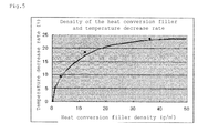
- a heat exchange paint including a heat conversion filler was applied on a steel plate and dried, and the surface was heated with an incandescent lamp. The relationship between the content density of the heat conversion filler and the temperature decrease rate was observed.
- Fig. 5 shows the results. The results of Fig. 5 clearly indicate that a good temperature decrease rate was obtained when the content density of the heat conversion filler was 3 to 35 g/m 2 .
Landscapes
- Photovoltaic Devices (AREA)
- Laminated Bodies (AREA)
Abstract
the heat conversion filler in the heat conversion layer having a density of 3 to 35 g/m2.
Description
- The present invention relates to a rear-surface protective sheet for solar cells that is disposed on the rear-surface of a solar cell, in particular to a rear-surface protective sheet for solar cells that has a function of suppressing temperature increase in a solar cell.
- Solar cells are mainly installed on rooftops of buildings. Because of direct heat from sunlight and heat from the roof, the temperature of the solar cell sometimes reaches 70°C or more. It is said that the conversion efficiency of crystalline silicon-based solar cells decreases by about 0.4%/°C as the temperature increases. Further, a rear-surface protective sheet for solar cells is typically applied on the rear surface of a solar cell, and the resulting laminate is generally referred to as a solar cell module.
- Methods have been proposed to suppress temperature increase in solar cells.
-
Patent Literature 1 is directed to a heat-releasing membrane for a solar cell module, and a solar cell module including the heat-releasing membrane. Specifically,Patent Literature 1 discloses that providing a coating material layer having heat dissipation (heat-releasing membrane) on the rear surface of a solar cell decreases the module temperature. To provide the coating material layer with weather resistance, an overcoating or a weather-resistant film is required, and a material that does not hinder heat dissipation must be selected. -
Patent Literature 2 is directed to a mist spraying device. Specifically,Patent Literature 2 discloses spraying mist to a solar cell module by a mist spray system using a heat exchange paint to decrease the module temperature. The rear-surface protective sheet for solar cells and the solar cell disclosed inPatent Literature 2, do not themselves have a function of suppressing temperature increase. - The heat exchange paint mentioned above is a coating material containing a heat conversion molecule that has a function of converting thermal energy into vibrational energy to consume the thermal energy. This coating material is commercially available from Arbar Industrial Co., Ltd., under the product names of Tough Coat D42, Tough Coat D47, etc., and also referred to as a heat-consuming coating material.
-
- PTL 1:
JP2007-12967A - PTL 2:
JP2010-78264A - An object of the present invention is to provide a rear-surface protective sheet for solar cells that has a function of suppressing temperature increase in a solar cell.
- The present inventors conducted extensive research to attain the above object and found that the use of a rear-surface protective sheet for solar cells that has a specific heat conversion layer can attain the above object. The present invention was thus accomplished.
- Specifically, the present invention relates to the following rear-surface protective sheets for solar cells.
- 1. A rear-surface protective sheet for solar cells that is disposed on a rear surface of a solar cell, comprising at least one heat conversion layer containing a heat conversion filler having a function of converting thermal energy to vibrational energy to consume the thermal energy,
the heat conversion filler in the heat conversion layer having a density of 3 to 35 g/m2. - 2. The rear-surface protective sheet for solar cells according to
Item 1, wherein the rear-surface protective sheet comprises a resin film substrate, and the heat conversion layer is formed on one side or both sides of the resin film substrate. - 3. The rear-surface protective sheet for solar cells according to
Item 1, wherein the rear-surface protective sheet comprises at one side of the resin film substrate a heat-sealing layer that is to be bonded to the rear surface of the solar cell, and a weather-resistant film at the other side, and the heat conversion layer is formed on one side or both sides of the resin film substrate. - 4. The rear-surface protective sheet for solar cells according to any one of
Items 1 to 3, wherein the heat conversion layer is formed by applying and drying a coating material containing the heat conversion filler. - 5. The rear-surface protective sheet for solar cells according to any one of
Items 1 to 4, wherein the heat-sealing layer comprises a component that can be heat-sealed with an ethylene acetic vinyl copolymer. - The rear-surface protective sheet for solar cells of the present invention is explained in detail below.
- The rear-surface protective sheet for solar cells of the present invention is disposed on the rear surface of a solar cell. The rear-surface protective sheet includes a heat conversion layer containing a heat conversion filler that has a function of converting thermal energy into vibrational energy to consume the thermal energy. The heat conversion filler in the heat conversion layer has a density of 3 to 35 g/m2.
- The rear-surface protective sheet for solar cells of the present invention, having the features mentioned above, can suppress the temperature increase of a solar cell because the heat conversion filler in the heat conversion layer converts thermal energy into vibrational energy to thereby consume the thermal energy. It is desired that a coating film that suppresses temperature increase by using reflection or radiation of thermal energy be formed at the outermost layer; however, since the heat conversion layer used in the present invention can consume heat energy even when it is not formed as the outermost layer, the heat conversion layer of the present invention can be formed as an inner layer (a layer that is not exposed on the surface of the sheet). Further, a material that does not interfere with heat dissipation has been required for forming a weather-resistant film at the outermost layer; however, any of a wide variety of known weather-resistant films can be used in the present invention.
- The known layer structure of a rear-surface protective sheet for solar cells is generally such that a heat-sealing layer (for adhering to the rear surface of a solar cell) is applied on a resin film substrate via an adhesive layer. A layer structure in which a weather-resistant film is applied on the other side of the resin film substrate via an adhesive layer is also known.
- The heat conversion layer used in the present invention can be formed at any position as long as it does not hinder the adhesion of the rear surface of the solar cell and the rear-surface protective sheet for solar cells via the heat-sealing layer. The rear-surface protective sheet for solar cells of the present invention has, for example, layer structures (a) to (d) shown in
Fig. 1 . - In layer structure (a) of
Fig. 1 , heat-sealing layer 2 is formed onresin film substrate 1 viaadhesive layer 3, andheat conversion layer 4 is formed on the other side ofresin film substrate 1. - Layer structure (b) of
Fig. 1 is the same as layer structure (a) ofFig. 1 , except that weather-resistant film 5 is formed on the outer side ofheat conversion layer 4 viaadhesive layer 3. Such a formation of weather-resistant film 5 on the outermost layer can increase the scratch resistance of the rear-surface protective sheet for solar cells, and prevent or suppress damage to the heat conversion layer. - Layer structure (c) of
Fig. 1 is the same as layer structure (b) ofFig. 1 , except thatheat conversion layer 4 formed on one side ofresin film substrate 1 is formed on both sides ofresin film substrate 1. Formingheat conversion layer 4 on only one side ofresin film substrate 1 may curl the laminate during the formation ofheat conversion layer 4. Such curling can be prevented or suppressed whenheat conversion layer 4 is formed on both sides ofresin film substrate 1 as in layer structure (c) ofFig. 1 . - In layer structure (d) of
Fig. 1 ,adhesive layer 3 andheat conversion layer 4 in layer structure (c) ofFig. 1 are combined into one layer (layer 6). In other words, layer 6 is a heat conversion layer and an adhesive layer. Layer 6 can be obtained by mixing the heat conversion filler used in the present invention with a composition for forming the adhesive layer in a manner such that the composition has a desired density, and forming a membrane. - Layer structures (a) to (d) are merely examples, and of course other layer structures can be used. The addition of the heat conversion filler to the resin film substrate or the weather-resistant film can impart the function of the heat conversion layer to these layers.
- The resin film substrate, heat-sealing layer, adhesive layer, heat conversion layer, and weather-resistant film are explained in detail below.
- The resin film substrate is not limited. A wide variety of resin film substrates used for known rear-surface protective sheets for solar cells can be used. For example, it is possible to use resin film substrates made of polyethylene terephthalate, polyethylenenaphthalate, polypropylene, polyamide, polyimide, polycarbonate, polyacrylicnitrile, polycycloolefin, polyphenylene ether, etc.
- As a substrate, it is possible to use metallic foil such as aluminum foil to increase thermal conductivity, thereby enhancing the heat conversion effect; however, it is necessary to make a hole in the rear-surface protective sheet for solar cells to draw out the electrode wires when the sheet is bonded to the solar cell. Since a metal-containing rear-surface protective sheet for solar cells may short-circuit the solar cell when the insulation is inadequate, the use of a resin film substrate as in the present invention is preferred. However, with adequate insulation, metallic foil such as aluminum foil can be used together with a resin film substrate, as required.
- The thickness of the resin film substrate is not limited, and it is preferably 200 to 300 µm, and more preferably 100 to 250 µm. A resin film substrate that is too thin results in a low voltage resistance as a rear-surface protective sheet for solar cells. A resin film substrate that is too thick increases the weight of the rear-surface protective sheet for solar cells, and after being bonded to the rear surface of the solar cell, the sheet may peel off from the solar cell with long-term use.
- The heat-sealing layer is the surface layer (solar cell side) of the rear-surface protective sheet for solar cells, and is bonded to the solar-cell sealing material (which is disposed on the lowermost layer of the solar cell and typically includes an ethylene-vinyl acetate copolymer (EVA)). The heat-sealing layer is not limited as long as it adheres to the sealing material. The heat-sealing layer preferably includes a component that can be heat-sealed with EVA. In view of adhesion with EVA, it is preferred to use linear low-density polyethylene (0.910 to 0.940 g/cm3) as a matrix of the heat-sealing layer.
- The heat-sealing layer preferably includes an inorganic-based ultraviolet ray absorber to prevent yellowing due to ultraviolet rays. Examples of the inorganic-based ultraviolet ray absorber include titanium oxide, zinc oxide, zirconium oxide, calcium carbonate, cerium oxide, aluminum oxide, silica, iron oxide, carbon, and the like. Of these, titanium oxide and carbon are preferred.
- The ultraviolet ray absorber preferably has a mean particle diameter of 0.1 to 5 µm. Ultraviolet ray absorbers that have a mean particle diameter exceeding 5 µm result in poor dispersibility, making it impossible to obtain a uniform ultraviolet ray absorption effect. Ultraviolet ray absorbers that have a mean particle diameter of less than 0.1 µm are not favorable in terms of cost.
- The ultraviolet ray absorber is preferably contained in an amount of 0.1 to 30 mass% to obtain a sufficient ultraviolet ray absorption effect and maintain good adhesion with the sealing agent, i.e., EVA. An ultraviolet ray absorber in an amount less than 0.1 mass% does not ensure a sufficient ultraviolet ray absorption effect and may result in yellowing due to ultraviolet rays. An ultraviolet ray absorber in an amount exceeding 30 mass% may decrease adhesion with EVA.
- The ultraviolet ray transmission rate of the heat-sealing layer is preferably 20% or less. A heat-sealing layer with an ultraviolet ray transmission rate exceeding 20% may result in yellowing due to insufficient ultraviolet-ray absorption effect. Although the lower limit of the ultraviolet-ray transmission rate is not particularly limited, it is generally about 1%.
- The thickness of the heat-sealing layer is not limited. The heat-sealing layer preferably has a thickness of 5 to 200 µm, and more preferably 30 to 180 µm to fully contain the ultraviolet ray absorber. A heat-sealing layer with a thickness less than 5 µm may not contain a sufficient amount of ultraviolet ray absorber.
- The adhesive layer for adhering layers of the rear-surface protective sheet for solar cells is not limited. For example, layers can be bonded using a urethane-based adhesive according to a dry lamination method.
- Examples of the urethane-based adhesive include two-component curable urethane-based adhesives, polyether urethane-based adhesives, polyester polyurethane polyol-based adhesives, etc. Of these, two-component curable urethane-based adhesives are preferred. The type and the thickness of the adhesive can be suitably determined according to the type of layer to be bonded.
- The heat conversion layer includes a heat conversion filler (heat conversion molecule) that converts thermal energy into vibrational energy to thereby consume the thermal energy. Infrared radiation contained in sunrays, etc., is converted into thermal energy when spread to the heat conversion layer, and then dispersed and moved in the heat conversion layer; however, the infrared radiation is immediately converted to vibrational energy when it comes into contact with the heat conversion filler in the heat conversion layer. Most of heat energy is promptly consumed because the energy conversion occurs on the surface layer of the heat conversion filler. Therefore, the heat energy in the heat conversion layer is consumed without being accumulated. In the present invention, the heat conversion layer can also improve the voltage resistance of the rear-surface protective sheet for solar cells.
- In the present invention, the density of the heat conversion filler in the heat conversion layer (the content density, i.e., the coating amount of the heat conversion filler) may be 3 to 35 g/m2, and preferably 10 to 35 g/m2. A heat conversion filler with a density of less than 3 g/m2 may result in insufficient heat conversion efficiency. A heat conversion filler with a density exceeding 35 g/m2 does not ensure heat conversion efficiency improvement commensurate with the content of the heat conversion filler. Accordingly, in the present invention, the heat conversion filler has a density of 3 to 35g/m2.
- The heat conversion layer is preferably formed by applying and drying a coating material containing the heat conversion filler. The coating material is referred to as a heat exchange paint (heat-consuming coating material), and is commercially available from Arbar Industrial Co., Ltd., under the product names of Tough Coat D42, Tough Coat D47, etc.
- Tough Coat D42, mentioned above, is a two-component curable heat exchange paint in which the main agent contains an acrylic polyol resin and a heat conversion filler, and the curing agent contains isocyanate (HMDI: hexamethylene diisocyanate). Tough Coat D47 is an aqueous one-component curable heat exchange paint that contains a styrene acrylic ester copolymer resin, a thermoplastic urethane resin, and a heat conversion filler.
- A heat conductive filler may be added to the heat conversion layer to increase the thermal conduction efficiency. Examples of the heat conductive filler include aluminum powder, nitriding aluminum, boron nitride, silicon oxide, aluminum oxide, magnesium oxide, etc. These heat conductive fillers can be used singly or as a mixture of two or more.
- Although the thickness of the heat conversion layer is not limited, it is preferably 10 to 200 µm, more preferably 20 to 150 µm, and most preferably 50 to 100 µm. A heat conversion layer with a thickness less than 10 µm results in poor heat conversion efficiency, while a heat conversion layer with a thickness exceeding 200 µm does not ensure the heat conversion efficiency improvement commensurate with increase in film thickness. The heat conversion layer may be formed on one side or both sides of the resin film substrate, as described above. When the layer is formed on both sides of the substrate, it is preferable to form layers separately so that the total thickness is within the aforementioned range.
- When the heat conversion layer plays a role of an adhesive layer, the heat conversion filler is added to a composition forming the adhesive layer in a desired density, and the resultant is used as a heat conversion layer and an adhesive layer.
- The weather-resistant film is not limited. It is possible to use a wide variety of weather-resistant films used for known rear-surface protective sheets for solar cells. Examples of a film having weather resistance and electric insulation include polyester films such as polyethylenenaphthalate (PEN) and polyethylene terephthalate (PET); fluorine-based films such as polyvinylidene fluoride (PVDF), polyvinyl fluoride (PVF), and ethylenetetrafluoroethylene (ETFE); polyolefin films such as polyethylene and polypropylene; polystyrene films; polyamide films; polyvinylchloride films; polycarbonate films; polyacrylicnitrile films; polyimide films; and the like. In view of outdoor durability, hydrolysis-resistant PET can be preferably used.
- Engineering plastics and fluororesins are other examples. Examples of the engineering plastics include polyacetal (POM), polyamide (PA), polycarbonate (PC), modified polyphenylene ether (m-PPE), polybutylene terephthalate (PBT), GF strengthening polyethylene terephthalate (GF-PET), ultra-high-molecular-weight polyethylene (UHPE), syndiotactic polystyrene (SPS), amorphism polyarylate (PAR), polysulfone (PSF), polyether sulfone (PES), polyphenylene sulfide (PPS), polyether ether ketone (PEEK), polyimide (PI), polyetherimide (PEI), polyphenylene ether (PPE), liquid crystal polymer (LCP), etc.
- The weather-resistant film can be a single layer or multiple layers (laminated films). A single layer preferably has a thickness of 20 to 250 µm. Multiple layers are preferably a laminate including a film having excellent weather resistance and a film having excellent electric insulation. In the laminate, it is preferable to dispose the film with excellent electric insulation at the resin film substrate side and dispose the film with excellent weather resistance at the outermost layer. The film with excellent weather resistance is preferably a fluorine-based film with a thickness of 20 to 150 µm, and the film with excellent electric insulation is preferably a PET film with a thickness of 100 to 250 µm.
- The rear-surface protective sheet for solar cells of the present invention can suppress the temperature increase of a solar cell because the heat conversion filler in the heat conversion layer converts thermal energy into vibrational energy to thereby consume the thermal energy. It is desired that a coating film that suppresses temperature increase by using reflection or radiation of thermal energy be formed at the outermost layer; however, since the heat conversion layer used in the present invention can consume heat energy even when it is not formed as the outermost layer, the heat conversion layer of the present invention can be formed as an inner layer (a layer that is not exposed on the surface of the sheet). Further, a material that does not interfere with heat dissipation has been required for forming a weather-resistant film at the outermost layer; however, any of a wide variety of known weather-resistant films can be used in the present invention.
-
-
Fig. 1 shows layer structures of the rear-surface protective sheets for solar cells of the present invention. -
Fig. 2A shows the layer structure of the rear-surface protective sheets for solar cells prepared in Example 1 and Comparative Example 1.Fig. 2B shows the layer structure of the rear-surface protective sheets for solar cells prepared in Example 2 and Comparative Example 2.Fig. 2C shows the layer structure of the rear-surface protective sheets for solar cells prepared in Example 3 and Comparative Example 3.Fig. 2D shows the layer structure of the rear-surface protective sheets for solar cells prepared in Examples 4 to 6 and Comparative Examples 4 to 6. -
Fig. 3 shows a simulated module used in Test Example 1. -
Fig. 4 shows a heating device used in Test Example 1. -
Fig. 5 shows a relation between the density (g/m2) of the heat conversion filler and the temperature decrease rate (%). - The present invention is explained in detail below with reference to Examples and Comparative Examples; however, the present invention is not limited to the Examples.
- Heat exchange paint D-47 (produced by Arbar Industrial Co., Ltd.) was applied on one side of a polyester film (produced by Teijin Limited., 125 µm) in an amount of 100 µm. The content density of the heat conversion filler was 12 g/m2. By using a dry laminating adhesive according to a dry lamination method, a linear low-density polyethylene film (produced by Tamapoly Co., Ltd., 50 µm) was bonded as a heat-sealing layer to be bonded to an EVA sealing material to the side on which the heat exchange paint was not applied. As the dry laminating adhesive, a polyurethane-based adhesive obtained by mixing Takelac A315 (100 parts by weight) and Takenate A50 (10 parts by weight) produced by Mitsui Chemicals, Inc., was used in an amount of 5 g/m2 (solid). Thus, a rear-surface protective sheet for solar cells was produced.
- Heat exchange paint D-47 (Arbar Industrial Co., Ltd.) was applied to each side of a polyester film (produced by Teijin Limited, 125 µm) in an amount of 50 µm. The content density of the heat conversion filler was 12 g/m2. A PVF film (Tedlar produced by DuPont, 38 µm) was applied on one side as a layer providing weather resistance, and a linear low-density polyethylene film (produced by Tamapoly Co., Ltd., 50 µm) was applied on the other side as a heat-sealing layer to be bonded to an EVA sealing material by using a dry laminating adhesive according to a dry lamination method. As the dry laminating adhesive, a polyurethane-based adhesive obtained by mixing Takelac A315 (100 parts by weight) and Takenate A50 (10 parts by weight) produced by Mitsui Chemicals, Inc., was used in an amount of 5 g/m2 (solid). Thus, a rear-surface protective sheet for solar cells was produced.
- Heat exchange paint D-47 (produced by Arbar Industrial Co., Ltd.) was applied on one side of a polyester film (produced by Teijin Limited, 125 µm) in an amount of 100 µm. The content density of the heat conversion filler was 12 g/m2. A PVF film (Tedlar produced by DuPont, 38 µm) was applied as a layer providing weather resistance on the side on which the heat exchange paint was not applied, and a linear low-density polyethylene film (produced by Tamapoly Co., Ltd., 50 µm) was applied as a heat-sealing layer to be bonded to an EVA sealing material by using a dry laminating adhesive according to a dry lamination method. As the dry laminating adhesive, a polyurethane-based adhesive obtained by mixing Takelac A315 (100 parts by weight) and Takenate A50 (10 parts by weight) produced by Mitsui Chemicals, Inc., was used in an amount of 5 g/m2 (solid). Thus, a rear-surface protective sheet for solar cells was produced.
- Rear-surface protective sheets for solar cells were obtained in the same manner as in Example 3 except that the thickness of the heat conversion coating layer was changed to 10 µm, 200 µm, and 300 µm, respectively.
- Rear-surface protective sheets for solar cells were obtained in the same manner as in Examples 1 to 6 except that the heat conversion layer was not provided.
- As shown in
Fig. 3 , glass, EVA, a thermocouple, EVA, and a sample were layered in this order (glass/EVA/thermocouple/EVA/sample), and a simulated module was made using a vacuum laminating machine (produced by NPC Incorporated.) (The slash indicates the lamination order.) - Rear-surface protective sheets for solar cells produced in Examples 1 to 6 and Comparative Examples 1 to 6 were used as samples.
- As shown in
Fig. 4 , the sheets were placed on a hot plate so that the glass surfaces faced the hot plate. The actual temperature of each thermocouple was measured, and the maximum temperature difference between the temperature of each example and the temperature of its corresponding comparative example was checked. - Table 1 below shows the test results.
Table 1 Actual temperature (°C) Maximum temperature difference (°C) Example 1 64.1 -1.4 Example 2 65.7 -1.8 Example 3 59.6 -0.6 Example 4 67.5 -0.5 Example 5 66.1 -2.8 Example 6 67.3 -3.0 Comparative Example 1 65.5 Comparative Example 2 67.5 Comparative Example 3 60.2 Comparative Example 4 68.0 Comparative Example 5 68.9 Comparative Example 6 70.3 - As is clear from the results of Table 1, in the heat conversion layer-containing rear-surface protective sheets for solar cells of Examples 1 to 6, the actual temperature of each thermocouple was lower than that of the corresponding Comparative Examples 1 to 6. Thus, the sheets of Examples 1 to 6 can suppress a temperature increase in a solar cell.
- A heat exchange paint including a heat conversion filler was applied on a steel plate and dried, and the surface was heated with an incandescent lamp. The relationship between the content density of the heat conversion filler and the temperature decrease rate was observed.
-
Fig. 5 shows the results. The results ofFig. 5 clearly indicate that a good temperature decrease rate was obtained when the content density of the heat conversion filler was 3 to 35 g/m2. -
- 1. Resin film substrate
- 2. Heat-sealing layer
- 3. Adhesive layer
- 4. Heat conversion layer
- 5. Weather-resistant film
- 6. Heat conversion layer and adhesive layer
- 7. Glass
- 8. EVA
- 9. Thermocouple
- 10. EVA
- 11. Sample
Claims (5)
- A rear-surface protective sheet for solar cells that is disposed on a rear surface of a solar cell, comprising at least one heat conversion layer containing a heat conversion filler having a function of converting thermal energy to vibrational energy to consume the thermal energy,
the heat conversion filler in the heat conversion layer having a density of 3 to 35 g/m2. - The rear-surface protective sheet for solar cells according to claim 1, wherein the rear-surface protective sheet comprises a resin film substrate, and the heat conversion layer is formed on one side or both sides of the resin film substrate.
- The rear-surface protective sheet for solar cells according to claim 1, wherein the rear-surface protective sheet comprises at one side of the resin film substrate a heat-sealing layer that is to be bonded to the rear surface of the solar cell, and a weather-resistant film at the other side, and the heat conversion layer is formed on one side or both sides of the resin film substrate.
- The rear-surface protective sheet for solar cells according to any one of claims 1 to 3, wherein the heat conversion layer is formed by applying and drying a coating material containing the heat conversion filler.
- The rear-surface protective sheet for solar cells according to any one of claims 1 to 4, wherein the heat-sealing layer comprises a component that can be heat-sealed with an ethylene acetic vinyl copolymer.
Applications Claiming Priority (2)
| Application Number | Priority Date | Filing Date | Title |
|---|---|---|---|
| JP2011139237A JP2013008776A (en) | 2011-06-23 | 2011-06-23 | Rear surface protective sheet for solar cell |
| PCT/JP2012/065821 WO2012176828A1 (en) | 2011-06-23 | 2012-06-21 | Rear surface protective sheet for solar cell |
Publications (2)
| Publication Number | Publication Date |
|---|---|
| EP2725625A1 true EP2725625A1 (en) | 2014-04-30 |
| EP2725625A4 EP2725625A4 (en) | 2015-05-13 |
Family
ID=47422659
Family Applications (1)
| Application Number | Title | Priority Date | Filing Date |
|---|---|---|---|
| EP12803488.1A Withdrawn EP2725625A4 (en) | 2011-06-23 | 2012-06-21 | REAR SURFACE PROTECTIVE SHEET FOR SOLAR CELL |
Country Status (7)
| Country | Link |
|---|---|
| US (1) | US20140209163A1 (en) |
| EP (1) | EP2725625A4 (en) |
| JP (1) | JP2013008776A (en) |
| KR (1) | KR20140027297A (en) |
| CN (1) | CN103608929A (en) |
| TW (1) | TWI569458B (en) |
| WO (1) | WO2012176828A1 (en) |
Families Citing this family (2)
| Publication number | Priority date | Publication date | Assignee | Title |
|---|---|---|---|---|
| CN111211257A (en) * | 2020-01-09 | 2020-05-29 | 珠海冠宇电池有限公司 | A flexible packaging film and secondary battery with photovoltaic properties |
| CN118254439B (en) * | 2024-03-28 | 2025-01-17 | 上海品诚晶曜光伏科技有限公司 | Light flame-retardant photovoltaic backboard and preparation method thereof |
Family Cites Families (8)
| Publication number | Priority date | Publication date | Assignee | Title |
|---|---|---|---|---|
| EP0562517B1 (en) * | 1992-03-23 | 1997-08-27 | Canon Kabushiki Kaisha | Solar cell with a polymer protective layer |
| KR100579191B1 (en) * | 2004-02-24 | 2006-05-11 | 삼성에스디아이 주식회사 | Thermal transfer element |
| JP4980589B2 (en) * | 2005-07-01 | 2012-07-18 | セラミッション株式会社 | Heat dissipation film for solar cell module and solar cell module provided with the heat dissipation film |
| JP4414416B2 (en) * | 2006-07-19 | 2010-02-10 | 亮三 林 | Reticulated shield |
| US20090288701A1 (en) * | 2008-05-23 | 2009-11-26 | E.I.Du Pont De Nemours And Company | Solar cell laminates having colored multi-layer encapsulant sheets |
| JP2010078264A (en) * | 2008-09-29 | 2010-04-08 | Hattori Kogyo Co Ltd | Mist spraying system |
| KR100909785B1 (en) * | 2008-11-24 | 2009-07-27 | 김경진 | Heat exchange paint and method of forming film of structure using same |
| JP5755405B2 (en) * | 2009-11-02 | 2015-07-29 | 恵和株式会社 | Radiation sheet for back surface of solar cell module and solar cell module using the same |
-
2011
- 2011-06-23 JP JP2011139237A patent/JP2013008776A/en active Pending
-
2012
- 2012-06-21 WO PCT/JP2012/065821 patent/WO2012176828A1/en not_active Ceased
- 2012-06-21 CN CN201280030650.XA patent/CN103608929A/en active Pending
- 2012-06-21 KR KR1020137030911A patent/KR20140027297A/en not_active Ceased
- 2012-06-21 US US14/128,162 patent/US20140209163A1/en not_active Abandoned
- 2012-06-21 EP EP12803488.1A patent/EP2725625A4/en not_active Withdrawn
- 2012-06-22 TW TW101122488A patent/TWI569458B/en not_active IP Right Cessation
Also Published As
| Publication number | Publication date |
|---|---|
| TWI569458B (en) | 2017-02-01 |
| US20140209163A1 (en) | 2014-07-31 |
| EP2725625A4 (en) | 2015-05-13 |
| CN103608929A (en) | 2014-02-26 |
| WO2012176828A1 (en) | 2012-12-27 |
| TW201306277A (en) | 2013-02-01 |
| JP2013008776A (en) | 2013-01-10 |
| KR20140027297A (en) | 2014-03-06 |
Similar Documents
| Publication | Publication Date | Title |
|---|---|---|
| TWI553086B (en) | Tape and solar assembly and articles made from it | |
| JP5655314B2 (en) | Solar cell module | |
| JP5734569B2 (en) | SOLAR CELL BACK SHEET, MANUFACTURING METHOD THEREOF, AND SOLAR CELL MODULE | |
| US20110277834A1 (en) | Polymer sheet for solar cell backsheet and solar cell module | |
| EP2571061A1 (en) | Backside protective sheet for solar cell and solar cell module comprising same | |
| JP5623938B2 (en) | Solar cell backsheet | |
| JP2000091610A (en) | Solar cell cover film, method of manufacturing the same, and solar cell module using the cover film | |
| WO2011087156A1 (en) | Solar cell back sheet film and method for producing the same | |
| WO2011099390A1 (en) | Solar cell backsheet and solar cell module | |
| EP2980860A1 (en) | Solar cell module | |
| CN103210503A (en) | Back sheet for solar cells, and solar cell module | |
| KR101622994B1 (en) | Protective sheet for solar cell, method for manufacturing the same, back sheet member for solar cell, back sheet for solar cell and solar cell module | |
| JP2011091303A (en) | Rear surface protective sheet for solar cell module and solar cell module using the same | |
| EP2850662A1 (en) | Photovoltaic backsheet | |
| EP2725625A1 (en) | Rear surface protective sheet for solar cell | |
| JP2010232233A (en) | Protective sheet for solar cell module, method for producing the same, and solar cell module | |
| CN103079823A (en) | Transparent protective sheet and solar cell module using same | |
| CN102468352A (en) | High-barrier flexible back film | |
| JP2012222227A (en) | Back sheet for solar cells, laminated body for the solar cells, solar cell module, and manufacturing methods of the back sheet, the laminated body, and the solar cell module | |
| JP2013042016A (en) | Polymer sheet for solar cell, back sheet for solar cell, and solar cell module | |
| CN102005491A (en) | High-fluorine mixcrystal coating solar photovoltaic cell back film and manufacturing method thereof | |
| CN105706251B (en) | Backside protective sheet used for solar batteries | |
| JP2007273737A (en) | Solar cell back surface protection sheet and solar cell module | |
| US20140150854A1 (en) | Patterned Transparent Photovoltaic Backsheet | |
| JP2008053420A (en) | Solar cell module sealing structure and manufacturing method |
Legal Events
| Date | Code | Title | Description |
|---|---|---|---|
| PUAI | Public reference made under article 153(3) epc to a published international application that has entered the european phase |
Free format text: ORIGINAL CODE: 0009012 |
|
| 17P | Request for examination filed |
Effective date: 20140102 |
|
| AK | Designated contracting states |
Kind code of ref document: A1 Designated state(s): AL AT BE BG CH CY CZ DE DK EE ES FI FR GB GR HR HU IE IS IT LI LT LU LV MC MK MT NL NO PL PT RO RS SE SI SK SM TR |
|
| DAX | Request for extension of the european patent (deleted) | ||
| RA4 | Supplementary search report drawn up and despatched (corrected) |
Effective date: 20150415 |
|
| RIC1 | Information provided on ipc code assigned before grant |
Ipc: B32B 7/02 20060101ALI20150409BHEP Ipc: H01L 31/042 20140101AFI20150409BHEP |
|
| 17Q | First examination report despatched |
Effective date: 20160323 |
|
| STAA | Information on the status of an ep patent application or granted ep patent |
Free format text: STATUS: THE APPLICATION IS DEEMED TO BE WITHDRAWN |
|
| 18D | Application deemed to be withdrawn |
Effective date: 20160803 |