EP2725584A2 - Ray emission device and imaging system having the same - Google Patents
Ray emission device and imaging system having the same Download PDFInfo
- Publication number
- EP2725584A2 EP2725584A2 EP20130189826 EP13189826A EP2725584A2 EP 2725584 A2 EP2725584 A2 EP 2725584A2 EP 20130189826 EP20130189826 EP 20130189826 EP 13189826 A EP13189826 A EP 13189826A EP 2725584 A2 EP2725584 A2 EP 2725584A2
- Authority
- EP
- European Patent Office
- Prior art keywords
- cylinder
- ray
- emission device
- ray emission
- beams
- Prior art date
- Legal status (The legal status is an assumption and is not a legal conclusion. Google has not performed a legal analysis and makes no representation as to the accuracy of the status listed.)
- Granted
Links
Images

Classifications
-
- G—PHYSICS
- G21—NUCLEAR PHYSICS; NUCLEAR ENGINEERING
- G21K—HANDLING OF PARTICLES OR IONISING RADIATION NOT OTHERWISE PROVIDED FOR; IRRADIATION DEVICES; GAMMA RAY OR X-RAY MICROSCOPES
- G21K1/00—Arrangements for handling particles or ionising radiation, e.g. focusing or moderating
- G21K1/02—Arrangements for handling particles or ionising radiation, e.g. focusing or moderating using diaphragms, collimators
- G21K1/04—Arrangements for handling particles or ionising radiation, e.g. focusing or moderating using diaphragms, collimators using variable diaphragms, shutters, choppers
-
- G—PHYSICS
- G21—NUCLEAR PHYSICS; NUCLEAR ENGINEERING
- G21K—HANDLING OF PARTICLES OR IONISING RADIATION NOT OTHERWISE PROVIDED FOR; IRRADIATION DEVICES; GAMMA RAY OR X-RAY MICROSCOPES
- G21K1/00—Arrangements for handling particles or ionising radiation, e.g. focusing or moderating
- G21K1/02—Arrangements for handling particles or ionising radiation, e.g. focusing or moderating using diaphragms, collimators
- G21K1/04—Arrangements for handling particles or ionising radiation, e.g. focusing or moderating using diaphragms, collimators using variable diaphragms, shutters, choppers
- G21K1/043—Arrangements for handling particles or ionising radiation, e.g. focusing or moderating using diaphragms, collimators using variable diaphragms, shutters, choppers changing time structure of beams by mechanical means, e.g. choppers, spinning filter wheels
-
- G—PHYSICS
- G01—MEASURING; TESTING
- G01N—INVESTIGATING OR ANALYSING MATERIALS BY DETERMINING THEIR CHEMICAL OR PHYSICAL PROPERTIES
- G01N23/00—Investigating or analysing materials by the use of wave or particle radiation, e.g. X-rays or neutrons, not covered by groups G01N3/00 – G01N17/00, G01N21/00 or G01N22/00
- G01N23/20—Investigating or analysing materials by the use of wave or particle radiation, e.g. X-rays or neutrons, not covered by groups G01N3/00 – G01N17/00, G01N21/00 or G01N22/00 by using diffraction of the radiation by the materials, e.g. for investigating crystal structure; by using scattering of the radiation by the materials, e.g. for investigating non-crystalline materials; by using reflection of the radiation by the materials
Definitions
- the present invention relates to a ray emission device and an imaging system having the ray emission device.
- Scattering imaging is generally applied by scanning an object point by point with a modulated ray pencil beam while receiving the point scanning signals by a detector. Images reflecting information of the object is acquired by one-to-one correspondence between the scanning positions and the signals when processing data.
- the key point lies in a method by which the ray is modulated and constrained into a pencil beam and a flying spot scanning is achieved, in such application.
- a rotary shield with one or more collimating holes is rotated in a sectorial scanning plane of the ray so that the ray is formed into a pencil beam for a flying spot by transmitting the ray through the one or more collimating holes, thereby achieving a scanning in a first dimensional direction.
- a detector with a large area is needed to cover a solid angle of scattered rays formed when the pencil beam hits the object as far as possible.
- the detector is moved (translated or rotated) with the sectorial scanning plane of ray relative to the object under inspection, thereby achieving a scanning in a second dimensional direction.
- the relative movement may be such that the sectorial scanning plane of ray and the detector move while the object is stationary, or the sectorial scanning plane of ray and the detector are stationary while the object moves.
- a set of motor drive device is needed to rotate the rotary shield when carrying out a scanning in the first dimensional direction, while another set of motor drive device is required to move the ray generating device, the rotary shield and the detector together relative to the object when performing a scanning in the second dimensional direction.
- two sets of mechanical drive devices are generally used to achieve a two-dimensional scanning in the prior art flying spot scanning method, and their real-time movement positions (or angles) are interrelated, and need accurate control.
- the two sets of mechanical drive devices have complicated mechanical structures. If the sectorial scanning plane of ray is rotated, then there is a further problem that the moment of inertia of the rotary shield is to be overcome.
- Continuous movement of the scanning in the second dimensional direction will cause an actual scanning line in the first dimensional direction not to be parallel to a movement direction in the first dimensional direction with an angle of inclination between the actual scanning line and the movement direction, thereby finally causing geometry deformation of the scan images, and deteriorating the images.
- an object of the present invention is to provide a ray emission device and an imaging system which can improve quality of the image.
- a ray emission device comprising: a cylinder; a ray source disposed in the cylinder for emitting a ray; and a collimator disposed in the cylinder, the collimator enabling the ray emitted by the ray source to form sectorial ray beams at a plurality of positions in an axial direction of the cylinder, wherein the cylinder has a pencil beam forming part arranged over an axial length of the cylinder corresponding to the plurality of positions, and wherein the sectorial ray beams are shaped into pencil beams through the pencil beam forming part when the cylinder rotates around a rotation axis.
- the pencil beam forming part is a plurality of discrete holes formed through a cylinder wall of the cylinder, or a slit formed through the cylinder wall of the cylinder.
- the collimator comprises a plurality of straight line-shaped gaps arranged in the axial direction of the cylinder and the ray emitted from the ray source substantially forms the sectorial ray beams through the gaps.
- the ray source comprises a plurality of focal spots arranged in the axial direction of the cylinder and corresponding to the plurality of straight line-shaped gaps.
- the collimator has a plate shape and abuts against the ray source.
- the pencil beams are formed in sequence in the axial direction of the cylinder through the pencil beam forming part.
- the formed sectorial ray beams are substantially aligned in the axial direction of the cylinder.
- the plurality of focal spots are located on the rotation axis of the cylinder.
- the cylinder is a hollow circular cylinder.
- the sectorial ray beams are substantially perpendicular to the rotation axis of the cylinder.
- the plurality of focal spots are independently controllable.
- the formed pencil beams are configured to perform a two-dimensional scan of an object.
- the collimator is made of a material which can shield the ray.
- the cylinder is made of a material which can shield the ray.
- an imaging system comprising: the ray emission device as above; and a detector for receiving a scattered ray scattered from an object under inspection when a ray emitted by the ray emission device hits the object.
- the ray emission device and the imaging system according to the present invention can achieve a scattering scan of the object under inspection.
- only scanning movement in the first dimensional direction is used, while the conventional scanning movement in the second dimensional direction is replaced with switching of focal spots of a multi-beam X-ray source.
- the switching of the focal spots can be achieved only by application of a digital control signal with a particular timing sequence. Therefore, a complicated mechanical structure of motor drive is greatly simplified and the scanning speed can be easily controlled. Since there is no scanning movement in the second dimensional direction, and there is only rotation of the rotary shield itself in one dimension, the problem that the moment of inertia of the rotary shield is to be overcome does not exist. Therefore, the present invention ensures that an actual scanning line in the first dimensional direction is always consistent with a movement direction in the first dimensional direction and geometry deformation will not occur in the scan images in principle.
- an imaging system 100 comprises: a ray emission device 30; a scatter detector 40 for receiving a scattered ray scattered from an object 6 under inspection when a ray emitted by the ray emission device 30 hits the object, and a control part 50.
- the ray emission device 30 comprises: a cylinder 31; a ray source 33 disposed in the cylinder 31 for emitting a ray; and a collimator 35 disposed in the cylinder 31.
- the collimator 35 enables the ray emitted by the ray source 33 to form sectorial ray beams 111 at a plurality of positions in an axial direction of the cylinder 31.
- the cylinder 31 has a pencil beam forming part 311 arranged over an axial length of the cylinder 31 corresponding to the plurality of positions.
- the sectorial ray beams 111 are shaped into pencil beams through the pencil beam forming part 311 when the cylinder 31 rotates around a rotation axis.
- the ray source 33 may be any appropriate existing multi-beam ray source.
- the ray source 33 may comprise a plurality of focal spots 101 arranged in the axial direction of the cylinder 31.
- the plurality of focal spots 101 are located on the rotation axis of the cylinder 31.
- the rotation axis may be a central axis of the cylinder 31.
- the plurality of focal spots 101 may be independently controllable.
- the ray source 33 may be an X-ray source.
- Each focal spot 101 can emit rays independently, and can be controlled by an external control signal to emit rays separately in a particular sequence.
- FIGS. 2a and 2b illustrate situations where the focal spots of the ray source 33 emit rays separately and simultaneously, respectively.
- the collimator 35 comprises a plurality of straight line-shaped gaps 351 arranged in the axial direction of the cylinder 31 and the ray emitted from the ray source 33 substantially forms the sectorial ray beams 111 through the gaps 351.
- the plurality of focal spots 101 may correspond to the plurality of straight line-shaped gaps 351.
- the collimator 35 has a plate shape and abuts against the ray source 33.
- the collimator 35 may be a stationary shield plate.
- the stationary shield plate is stationary relative to the ray source 33.
- the collimator 35 is made of a material, such as lead, tungsten, copper, steel, and lead tetraoxide, and preferably lead, which can shield the X-ray.
- the plurality of straight line-shaped gaps 351 are formed in the stationary shield plate. The ray emitted by the X-ray source 33 becomes the sectorial ray beams 111 after being collimated by the straight line-shaped gaps 351 in the stationary shield plate.
- the cylinder may be a hollow circular cylinder or a hollow cylinder having another shape.
- the pencil beam forming part 311 is a plurality of discrete holes 311 formed through a cylinder wall of the cylinder 31, or a slit formed through the cylinder wall of the cylinder 31.
- the slit may be a linear slot formed by connecting these through holes 311 and through which the ray can pass.
- the pencil beam forming part may have a shape of a circle, a rectangle, a rhombus, an ellipse or the like, and preferably a circle.
- the sectorial ray beams 111 can form the pencil beams through the pencil beam forming part 311 in sequence or in other orders in the axial direction of the cylinder 31, respectively.
- the pencil beams corresponding to the plurality of sectorial ray beams 111 can be formed one by one or at intervals in the axial direction of the cylinder 31, or they can be formed in other manners.
- the formed pencil beams are configured to perform a two-dimensional scan of an object.
- the formed sectorial ray beams 111 may be substantially aligned in the axial direction of the cylinder 31.
- the sectorial ray beams 111 may be substantially perpendicular to the rotation axis of the cylinder 31.
- the cylinder 31 may be a rotary shield and is made of a material which can shield the X-ray.
- the cylinder 31 may be formed of a single material such as lead, tungsten, copper, steel, and lead tetraoxide, or combination of the materials, and preferably a single material selected from the above group.
- a typical manner in which the cylinder is formed of combination of materials is as follows.
- the hollow cylinder consists of three cylinders fitted together.
- the outmost cylinder and the innermost cylinder are made of material, such as aluminum or steel, which has certain stiffness and hardness for fixation, while the intermediate cylinder is made of typical ray shielding material, such as lead, lead-antimony alloy, and tungsten, for shielding ray.
- the focal spots 101 of the ray source 33 may be configured such that one of the focal spots 101 of the ray source 33 can be aligned with only one of the holes 311 and emit a pencil beam without obstruction.
- the control part 50 controls the focal spot 101 to emit ray, and the pencil beam 112 emitted from the focal spot 101 moves along a straight line on the object 6 to complete a row of scan of the object.
- another one of the focal spots 101 of the ray source 33 can be aligned with another one of the holes 311.
- the control part 5 controls the other focal spot 101 to emit ray, and the pencil beam 113 emitted from the other focal spot moves along another straight line on the object to complete another row of scan of the object. And so on, as the cylinder 31 rotates at a uniform speed, the control part 5 controls the respective focal spots of the ray source 33 to emit the ray in sequence based on rotational position information of the cylinder 31 so as to complete the entire scan of the object 6 row by row. It needs only one-dimensional movement, i.e., the rotation of the cylinder 31, for the device to complete the scan.
- the detector 40 can acquire the rays scattered from the object 6 when the pencil beams hit the object 6, convert the scattered rays into digital data and transmit the same to a computer or the control part 50 for processing.
- the control part 50 can control the cylinder 31 to rotate, and control the respective emission focal spots 101 of the ray source 33 to emit the X-ray based on a rotational position of the cylinder 31.
- the control part 5 drives the cylinder 31 to rotate so that the scanning movement in the first dimensional direction can be achieved.
- the control part 5 acquires angular position information of the cylinder 31 and controls the respective focal spots of the ray source 33 to emit rays based on a predetermined timing sequence so as to achieve the scanning movement in the second dimensional direction.
- the detector 40 acquires the pencil beam of the ray acting on the object 6 and generates digital data. The scatter image is obtained by correspondence between the digital data and the positions of the acting points of the pencil beam of the ray.
- the present invention provides a ray emission device and an imaging system having the same.
- the ray emission device and the imaging system according to the present invention can achieve a scattering scan of the object under inspection.
- only scanning movement in the first dimensional direction is used, while the conventional scanning movement in the second dimensional direction is replaced with switching of focal spots of a multi-beam X-ray source.
- the switching of the focal spots can be achieved only by application of a digital control signal with a particular timing sequence. Therefore, a complicated mechanical structure of motor drive is greatly simplified and the scanning speed can be easily controlled.
- the present invention ensures that an actual scanning line in the first dimensional direction is always consistent with a movement direction in the first dimensional direction and geometry deformation will not occur in the scan images in principle.
Landscapes
- Physics & Mathematics (AREA)
- Spectroscopy & Molecular Physics (AREA)
- High Energy & Nuclear Physics (AREA)
- General Engineering & Computer Science (AREA)
- Engineering & Computer Science (AREA)
- Chemical & Material Sciences (AREA)
- Life Sciences & Earth Sciences (AREA)
- General Health & Medical Sciences (AREA)
- General Physics & Mathematics (AREA)
- Immunology (AREA)
- Pathology (AREA)
- Biochemistry (AREA)
- Analytical Chemistry (AREA)
- Health & Medical Sciences (AREA)
- Crystallography & Structural Chemistry (AREA)
- Analysing Materials By The Use Of Radiation (AREA)
- Apparatus For Radiation Diagnosis (AREA)
Abstract
Description
- The present invention relates to a ray emission device and an imaging system having the ray emission device.
- Scattering imaging is generally applied by scanning an object point by point with a modulated ray pencil beam while receiving the point scanning signals by a detector. Images reflecting information of the object is acquired by one-to-one correspondence between the scanning positions and the signals when processing data. The key point lies in a method by which the ray is modulated and constrained into a pencil beam and a flying spot scanning is achieved, in such application.
- In a conventional flying spot scanning method, a rotary shield with one or more collimating holes is rotated in a sectorial scanning plane of the ray so that the ray is formed into a pencil beam for a flying spot by transmitting the ray through the one or more collimating holes, thereby achieving a scanning in a first dimensional direction. In order to effectively improve detection efficiency, a detector with a large area is needed to cover a solid angle of scattered rays formed when the pencil beam hits the object as far as possible. Generally, the detector is moved (translated or rotated) with the sectorial scanning plane of ray relative to the object under inspection, thereby achieving a scanning in a second dimensional direction. The relative movement may be such that the sectorial scanning plane of ray and the detector move while the object is stationary, or the sectorial scanning plane of ray and the detector are stationary while the object moves. A set of motor drive device is needed to rotate the rotary shield when carrying out a scanning in the first dimensional direction, while another set of motor drive device is required to move the ray generating device, the rotary shield and the detector together relative to the object when performing a scanning in the second dimensional direction.
- As described above, two sets of mechanical drive devices are generally used to achieve a two-dimensional scanning in the prior art flying spot scanning method, and their real-time movement positions (or angles) are interrelated, and need accurate control. The two sets of mechanical drive devices have complicated mechanical structures. If the sectorial scanning plane of ray is rotated, then there is a further problem that the moment of inertia of the rotary shield is to be overcome.
- Continuous movement of the scanning in the second dimensional direction will cause an actual scanning line in the first dimensional direction not to be parallel to a movement direction in the first dimensional direction with an angle of inclination between the actual scanning line and the movement direction, thereby finally causing geometry deformation of the scan images, and deteriorating the images. The more a speed of the scanning movement in the second dimensional direction is, the more the deformation is. On the other hand, the less the speed of the scanning movement in the second dimensional direction is, the longer the entire scanning time of the system is.
- Therefore, there is a need for an improved flying spot scanning method which can effectively eliminate or alleviate the above dilemma.
- Accordingly, an object of the present invention is to provide a ray emission device and an imaging system which can improve quality of the image.
- In accordance with an aspect of the present invention, there is provided a ray emission device, comprising: a cylinder; a ray source disposed in the cylinder for emitting a ray; and a collimator disposed in the cylinder, the collimator enabling the ray emitted by the ray source to form sectorial ray beams at a plurality of positions in an axial direction of the cylinder, wherein the cylinder has a pencil beam forming part arranged over an axial length of the cylinder corresponding to the plurality of positions, and wherein the sectorial ray beams are shaped into pencil beams through the pencil beam forming part when the cylinder rotates around a rotation axis.
- In accordance with another aspect of the present invention, the pencil beam forming part is a plurality of discrete holes formed through a cylinder wall of the cylinder, or a slit formed through the cylinder wall of the cylinder.
- In accordance with a further aspect of the present invention, the collimator comprises a plurality of straight line-shaped gaps arranged in the axial direction of the cylinder and the ray emitted from the ray source substantially forms the sectorial ray beams through the gaps.
- In accordance with a still further aspect of the present invention, the ray source comprises a plurality of focal spots arranged in the axial direction of the cylinder and corresponding to the plurality of straight line-shaped gaps.
- In accordance with an aspect of the present invention, the collimator has a plate shape and abuts against the ray source.
- In accordance with an aspect of the present invention, when the cylinder is rotated, the pencil beams are formed in sequence in the axial direction of the cylinder through the pencil beam forming part.
- In accordance with an aspect of the present invention, the formed sectorial ray beams are substantially aligned in the axial direction of the cylinder.
- In accordance with an aspect of the present invention, the plurality of focal spots are located on the rotation axis of the cylinder.
- In accordance with an aspect of the present invention, the cylinder is a hollow circular cylinder.
- In accordance with an aspect of the present invention, the sectorial ray beams are substantially perpendicular to the rotation axis of the cylinder.
- In accordance with an aspect of the present invention, the plurality of focal spots are independently controllable.
- In accordance with an aspect of the present invention, the formed pencil beams are configured to perform a two-dimensional scan of an object.
- In accordance with an aspect of the present invention, the collimator is made of a material which can shield the ray.
- In accordance with an aspect of the present invention, the cylinder is made of a material which can shield the ray.
- In accordance with an aspect of the present invention, there is provided an imaging system, comprising: the ray emission device as above; and a detector for receiving a scattered ray scattered from an object under inspection when a ray emitted by the ray emission device hits the object.
- The ray emission device and the imaging system according to the present invention can achieve a scattering scan of the object under inspection. In the present invention, only scanning movement in the first dimensional direction is used, while the conventional scanning movement in the second dimensional direction is replaced with switching of focal spots of a multi-beam X-ray source. The switching of the focal spots can be achieved only by application of a digital control signal with a particular timing sequence. Therefore, a complicated mechanical structure of motor drive is greatly simplified and the scanning speed can be easily controlled. Since there is no scanning movement in the second dimensional direction, and there is only rotation of the rotary shield itself in one dimension, the problem that the moment of inertia of the rotary shield is to be overcome does not exist. Therefore, the present invention ensures that an actual scanning line in the first dimensional direction is always consistent with a movement direction in the first dimensional direction and geometry deformation will not occur in the scan images in principle.
-
-
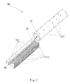
FIG. 1 is a schematic view of a ray emission device according to an embodiment of the present invention; -
FIG. 2a is a schematic view of a ray source and a collimator according to an embodiment of the present invention in which only one of focal spots emits rays; -
FIG. 2b is a schematic view of the ray source and the collimator according to the embodiment of the present invention in which all of the focal spots emit rays; -
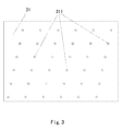
FIG. 3 is a deploying drawing of a cylinder according to an embodiment of the present invention; and -
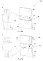
FIGS. 4a and 4b are schematic views of an imaging system according to an embodiment of the present invention. - A further description of the invention will be made as below with reference to embodiments of the present invention taken in conjunction with the accompanying drawings.
- As illustrated in
FIGS. 4a and 4b , animaging system 100 according to the present invention comprises: aray emission device 30; ascatter detector 40 for receiving a scattered ray scattered from anobject 6 under inspection when a ray emitted by theray emission device 30 hits the object, and acontrol part 50. - Referring to
FIG. 1 , theray emission device 30 comprises: acylinder 31; aray source 33 disposed in thecylinder 31 for emitting a ray; and acollimator 35 disposed in thecylinder 31. Thecollimator 35 enables the ray emitted by theray source 33 to formsectorial ray beams 111 at a plurality of positions in an axial direction of thecylinder 31. Thecylinder 31 has a pencilbeam forming part 311 arranged over an axial length of thecylinder 31 corresponding to the plurality of positions. Thesectorial ray beams 111 are shaped into pencil beams through the pencilbeam forming part 311 when thecylinder 31 rotates around a rotation axis. - As illustrated in
FIGS. 1 ,2a and 2b , theray source 33 may be any appropriate existing multi-beam ray source. For example, theray source 33 may comprise a plurality offocal spots 101 arranged in the axial direction of thecylinder 31. The plurality offocal spots 101 are located on the rotation axis of thecylinder 31. The rotation axis may be a central axis of thecylinder 31. The plurality offocal spots 101 may be independently controllable. In addition, theray source 33 may be an X-ray source. Eachfocal spot 101 can emit rays independently, and can be controlled by an external control signal to emit rays separately in a particular sequence.FIGS. 2a and 2b illustrate situations where the focal spots of theray source 33 emit rays separately and simultaneously, respectively. - As illustrated in
FIGS. 1 ,2a and 2b , thecollimator 35 comprises a plurality of straight line-shapedgaps 351 arranged in the axial direction of thecylinder 31 and the ray emitted from theray source 33 substantially forms the sectorial ray beams 111 through thegaps 351. The plurality offocal spots 101 may correspond to the plurality of straight line-shapedgaps 351. Thecollimator 35 has a plate shape and abuts against theray source 33. - The
collimator 35 may be a stationary shield plate. The stationary shield plate is stationary relative to theray source 33. Thecollimator 35 is made of a material, such as lead, tungsten, copper, steel, and lead tetraoxide, and preferably lead, which can shield the X-ray. The plurality of straight line-shapedgaps 351 are formed in the stationary shield plate. The ray emitted by theX-ray source 33 becomes the sectorial ray beams 111 after being collimated by the straight line-shapedgaps 351 in the stationary shield plate. - As illustrated in
FIGS. 1 and3 , the cylinder may be a hollow circular cylinder or a hollow cylinder having another shape. The pencilbeam forming part 311 is a plurality ofdiscrete holes 311 formed through a cylinder wall of thecylinder 31, or a slit formed through the cylinder wall of thecylinder 31. The slit may be a linear slot formed by connecting these throughholes 311 and through which the ray can pass. The pencil beam forming part may have a shape of a circle, a rectangle, a rhombus, an ellipse or the like, and preferably a circle. - As illustrated in
FIGS. 1 ,3 ,4a, and 4b , when thecylinder 31 rotates, the sectorial ray beams 111 can form the pencil beams through the pencilbeam forming part 311 in sequence or in other orders in the axial direction of thecylinder 31, respectively. In other words, the pencil beams corresponding to the plurality of sectorial ray beams 111 can be formed one by one or at intervals in the axial direction of thecylinder 31, or they can be formed in other manners. The formed pencil beams are configured to perform a two-dimensional scan of an object. The formed sectorial ray beams 111 may be substantially aligned in the axial direction of thecylinder 31. The sectorial ray beams 111 may be substantially perpendicular to the rotation axis of thecylinder 31. - The
cylinder 31 may be a rotary shield and is made of a material which can shield the X-ray. Thecylinder 31 may be formed of a single material such as lead, tungsten, copper, steel, and lead tetraoxide, or combination of the materials, and preferably a single material selected from the above group. A typical manner in which the cylinder is formed of combination of materials is as follows. The hollow cylinder consists of three cylinders fitted together. The outmost cylinder and the innermost cylinder are made of material, such as aluminum or steel, which has certain stiffness and hardness for fixation, while the intermediate cylinder is made of typical ray shielding material, such as lead, lead-antimony alloy, and tungsten, for shielding ray. - As illustrated in
FIGS. 4a, and 4b , thefocal spots 101 of theray source 33 may be configured such that one of thefocal spots 101 of theray source 33 can be aligned with only one of theholes 311 and emit a pencil beam without obstruction. As thecylinder 31 rotates, thecontrol part 50 controls thefocal spot 101 to emit ray, and thepencil beam 112 emitted from thefocal spot 101 moves along a straight line on theobject 6 to complete a row of scan of the object. As thecylinder 31 has rotated by an angle, another one of thefocal spots 101 of theray source 33 can be aligned with another one of theholes 311. The control part 5 controls the otherfocal spot 101 to emit ray, and thepencil beam 113 emitted from the other focal spot moves along another straight line on the object to complete another row of scan of the object. And so on, as thecylinder 31 rotates at a uniform speed, the control part 5 controls the respective focal spots of theray source 33 to emit the ray in sequence based on rotational position information of thecylinder 31 so as to complete the entire scan of theobject 6 row by row. It needs only one-dimensional movement, i.e., the rotation of thecylinder 31, for the device to complete the scan. - The
detector 40 can acquire the rays scattered from theobject 6 when the pencil beams hit theobject 6, convert the scattered rays into digital data and transmit the same to a computer or thecontrol part 50 for processing. - The
control part 50 can control thecylinder 31 to rotate, and control the respective emissionfocal spots 101 of theray source 33 to emit the X-ray based on a rotational position of thecylinder 31. - After the ray emitted from any of the focal spots of the
ray source 33 is collimated by thecollimator 35, only a portion of the ray that can pass through thehole 311 of thecylinder 31 can become the emitted pencil beam finally used for scan, while the rest is all shielded. The control part 5 drives thecylinder 31 to rotate so that the scanning movement in the first dimensional direction can be achieved. In addition, the control part 5 acquires angular position information of thecylinder 31 and controls the respective focal spots of theray source 33 to emit rays based on a predetermined timing sequence so as to achieve the scanning movement in the second dimensional direction. Thedetector 40 acquires the pencil beam of the ray acting on theobject 6 and generates digital data. The scatter image is obtained by correspondence between the digital data and the positions of the acting points of the pencil beam of the ray. - As described above, the present invention provides a ray emission device and an imaging system having the same. The ray emission device and the imaging system according to the present invention can achieve a scattering scan of the object under inspection. In the present invention, only scanning movement in the first dimensional direction is used, while the conventional scanning movement in the second dimensional direction is replaced with switching of focal spots of a multi-beam X-ray source. The switching of the focal spots can be achieved only by application of a digital control signal with a particular timing sequence. Therefore, a complicated mechanical structure of motor drive is greatly simplified and the scanning speed can be easily controlled. Since there is no scanning movement in the second dimensional direction, and there is only rotation of the rotary shield itself in one dimension, the problem that the moment of inertia of the rotary shield is to be overcome does not exist. Therefore, the present invention ensures that an actual scanning line in the first dimensional direction is always consistent with a movement direction in the first dimensional direction and geometry deformation will not occur in the scan images in principle.
Claims (12)
- A ray emission device, comprising:a cylinder;a ray source disposed in the cylinder for emitting a ray; anda collimator disposed in the cylinder, the collimator enabling the ray emitted by the ray source to form sectorial ray beams at a plurality of positions in an axial direction of the cylinder,wherein the cylinder has a pencil beam forming part arranged over an axial length of the cylinder corresponding to the plurality of positions, and wherein the sectorial ray beams form pencil beams through the pencil beam forming part when the cylinder rotates around a rotation axis.
- The ray emission device of claim 1, wherein the pencil beam forming part is a plurality of discrete holes formed through a cylinder wall of the cylinder.
- The ray emission device of claim 1, wherein the pencil beam forming part is a slit formed through a cylinder wall of the cylinder.
- The ray emission device of claim 1, wherein the collimator comprises a plurality of straight line-shaped gaps arranged in the axial direction of the cylinder and the ray emitted from the ray source substantially forms the sectorial ray beams through the gaps.
- The ray emission device of claim 4, wherein
the ray source comprises a plurality of focal spots arranged in the axial direction of the cylinder and corresponding to the plurality of straight line-shaped gaps. - The ray emission device of claim 1, wherein
when the cylinder is rotated, the pencil beams are formed in sequence in the axial direction of the cylinder through the pencil beam forming part. - The ray emission device of claim 5, wherein
the plurality of focal spots are located on the rotation axis of the cylinder. - The ray emission device of claim 1, wherein
the cylinder is a hollow circular cylinder. - The ray emission device of claim 1, wherein
the sectorial ray beams are substantially perpendicular to the rotation axis of the cylinder. - The ray emission device of claim 1, wherein
the collimator is made of a material which can shield rays. - The ray emission device of claim 1, wherein
the cylinder is made of a material which can shield rays. - An imaging system, comprising:the ray emission device of claim 1; anda detector for receiving a scattered ray scattered from an object under inspection when a ray emitted by the ray emission device hits the object.
Applications Claiming Priority (1)
| Application Number | Priority Date | Filing Date | Title |
|---|---|---|---|
| CN201210409265.8A CN103776848B (en) | 2012-10-24 | 2012-10-24 | Radiation-emitting device and imaging system |
Publications (3)
| Publication Number | Publication Date |
|---|---|
| EP2725584A2 true EP2725584A2 (en) | 2014-04-30 |
| EP2725584A3 EP2725584A3 (en) | 2014-05-07 |
| EP2725584B1 EP2725584B1 (en) | 2016-04-27 |
Family
ID=49485518
Family Applications (1)
| Application Number | Title | Priority Date | Filing Date |
|---|---|---|---|
| EP13189826.4A Active EP2725584B1 (en) | 2012-10-24 | 2013-10-23 | Imaging system having an X-ray emission device |
Country Status (6)
| Country | Link |
|---|---|
| US (1) | US9031192B2 (en) |
| EP (1) | EP2725584B1 (en) |
| CN (1) | CN103776848B (en) |
| PL (1) | PL2725584T3 (en) |
| RU (1) | RU2545095C1 (en) |
| WO (1) | WO2014063627A1 (en) |
Families Citing this family (6)
| Publication number | Priority date | Publication date | Assignee | Title |
|---|---|---|---|---|
| US9208918B2 (en) * | 2012-11-16 | 2015-12-08 | Neurologica Corp. | Computerized tomography (CT) imaging system with multi-slit rotatable collimator |
| CN105301669B (en) | 2015-12-04 | 2019-01-04 | 同方威视技术股份有限公司 | Rays safety detection apparatus and X-ray detection X method |
| US10714227B2 (en) * | 2016-06-06 | 2020-07-14 | Georgetown Rail Equipment Company | Rotating radiation shutter collimator |
| DE102018109595A1 (en) * | 2018-04-20 | 2019-10-24 | Carl Zeiss Meditec Ag | X-ray apparatus for medical applications |
| DE102021103037B3 (en) * | 2021-02-09 | 2022-03-31 | Bruker Axs Gmbh | Adjustable segmented collimator |
| CN114155990B (en) * | 2021-12-30 | 2025-06-27 | 同方威视科技(北京)有限公司 | Radiation source devices and radiation inspection equipment |
Family Cites Families (23)
| Publication number | Priority date | Publication date | Assignee | Title |
|---|---|---|---|---|
| US1730976A (en) * | 1928-06-13 | 1929-10-08 | Jenkins Lab | Helical drum scanner |
| US1963255A (en) * | 1929-10-28 | 1934-06-19 | Rca Corp | Scanning device |
| GB464919A (en) * | 1935-09-24 | 1937-04-26 | Hans Gerhard Lubszynski | Improvements in or relating to television transmitting and the like systems |
| US2354199A (en) * | 1939-01-03 | 1944-07-25 | Lee A Collins | Method and means for television and other transmissions |
| US5022062A (en) * | 1989-09-13 | 1991-06-04 | American Science And Engineering, Inc. | Automatic threat detection based on illumination by penetrating radiant energy using histogram processing |
| US6094472A (en) * | 1998-04-14 | 2000-07-25 | Rapiscan Security Products, Inc. | X-ray backscatter imaging system including moving body tracking assembly |
| CN1107882C (en) * | 1999-08-25 | 2003-05-07 | 沈阳师范学院 | Multifunctional industrial X-ray imaging system |
| US20040256565A1 (en) * | 2002-11-06 | 2004-12-23 | William Adams | X-ray backscatter mobile inspection van |
| CN2645079Y (en) * | 2003-08-22 | 2004-09-29 | 貊大卫 | Backscattering X-ray scanner |
| CN1207558C (en) * | 2003-08-22 | 2005-06-22 | 貊大卫 | Backscattering type X-ray scanner |
| US7809109B2 (en) * | 2004-04-09 | 2010-10-05 | American Science And Engineering, Inc. | Multiple image collection and synthesis for personnel screening |
| WO2006102274A1 (en) * | 2005-03-21 | 2006-09-28 | American Science And Engineering, Inc. | Increased detectability and range for x-ray backscatter imaging systems |
| WO2008063695A2 (en) * | 2006-04-21 | 2008-05-29 | American Science And Engineering, Inc. | X-ray imaging of baggage and personnel using arrays of discrete sources and multiple collimated beams |
| CN200941097Y (en) * | 2006-07-27 | 2007-08-29 | 上海英迈吉东影图像设备有限公司 | Imaging apparatus having X-ray back scatter and fault scan |
| KR101110712B1 (en) * | 2006-11-09 | 2012-02-24 | 캐논 가부시끼가이샤 | Radiographic imaging control apparatus using multi radiation generating apparatus |
| FR2926924B1 (en) * | 2008-01-25 | 2012-10-12 | Thales Sa | RADIOGENIC SOURCE COMPRISING AT LEAST ONE ELECTRON SOURCE ASSOCIATED WITH A PHOTOELECTRIC CONTROL DEVICE |
| WO2009104156A1 (en) * | 2008-02-22 | 2009-08-27 | Philips Intellectual Property & Standards Gmbh | High-resolution quasi-static setup for x-ray imaging with distributed sources |
| WO2009129488A1 (en) * | 2008-04-17 | 2009-10-22 | University Of Florida Research Foundation, Inc. | Method and apparatus for computed imaging backscatter radiography |
| CN201285377Y (en) * | 2008-08-05 | 2009-08-05 | 同方威视技术股份有限公司 | Radiation beam scanning apparatus for back scattering imaging |
| CN102116747B (en) * | 2009-12-30 | 2014-04-30 | 同方威视技术股份有限公司 | A scanning device and method for a ray beam for backscattered imaging |
| PL2633294T3 (en) * | 2010-10-27 | 2020-11-02 | American Science & Engineering, Inc. | Versatile x-ray beam scanner |
| CN202177591U (en) * | 2011-07-07 | 2012-03-28 | 董明 | X-ray rotating disk type breaker flying spot forming device |
| CN202837210U (en) * | 2012-10-24 | 2013-03-27 | 同方威视技术股份有限公司 | Ray transmitting device and imaging system |
-
2012
- 2012-10-24 CN CN201210409265.8A patent/CN103776848B/en active Active
-
2013
- 2013-10-22 US US14/060,270 patent/US9031192B2/en active Active
- 2013-10-23 EP EP13189826.4A patent/EP2725584B1/en active Active
- 2013-10-23 WO PCT/CN2013/085789 patent/WO2014063627A1/en not_active Ceased
- 2013-10-23 RU RU2013147394/28A patent/RU2545095C1/en active
- 2013-10-23 PL PL13189826.4T patent/PL2725584T3/en unknown
Non-Patent Citations (1)
| Title |
|---|
| None |
Also Published As
| Publication number | Publication date |
|---|---|
| CN103776848A (en) | 2014-05-07 |
| US9031192B2 (en) | 2015-05-12 |
| CN103776848B (en) | 2017-08-29 |
| RU2013147394A (en) | 2015-04-27 |
| RU2545095C1 (en) | 2015-03-27 |
| EP2725584A3 (en) | 2014-05-07 |
| EP2725584B1 (en) | 2016-04-27 |
| WO2014063627A1 (en) | 2014-05-01 |
| PL2725584T3 (en) | 2016-12-30 |
| US20140177802A1 (en) | 2014-06-26 |
Similar Documents
| Publication | Publication Date | Title |
|---|---|---|
| JP5696226B2 (en) | Radiation beam scanning apparatus and method for backscatter imaging | |
| US9031192B2 (en) | Ray emission device and imaging system having the same | |
| EP2520927B1 (en) | Scanning device using radiation beams for backscatter imaging and method thereof | |
| US7142629B2 (en) | Stationary computed tomography system and method | |
| EP4187237B1 (en) | Backscatter imaging device, control method, and inspection system | |
| CN201285377Y (en) | Radiation beam scanning apparatus for back scattering imaging | |
| CN103776847B (en) | Radiation-emitting device and imaging system | |
| CN202013328U (en) | Ray bundle scanning device for back scattering imaging | |
| CN202837210U (en) | Ray transmitting device and imaging system | |
| CN113834834B (en) | Backscatter imaging device and backscatter detection system | |
| CN216449466U (en) | Back scattering imaging device and back scattering detection system | |
| US9978471B2 (en) | Flying spot forming apparatus and design method | |
| HK1195619A (en) | Ray emission device and imaging system | |
| HK1195619B (en) | Ray emission device and imaging system | |
| HK1195618B (en) | Radiation-emitting device and the imaging system | |
| CN120559001B (en) | Backscatter imaging device and line scan imaging method | |
| HK1175238B (en) | Device and method for scanning ray bundles for backscatter imaging | |
| CN105987920B (en) | A kind of flying spot forms device and design method | |
| HK1227998A1 (en) | Flying spot forming apparatus and design method | |
| HK1159752B (en) | Scanning device using ray beam for backscattering imaging and method thereof |
Legal Events
| Date | Code | Title | Description |
|---|---|---|---|
| PUAL | Search report despatched |
Free format text: ORIGINAL CODE: 0009013 |
|
| PUAI | Public reference made under article 153(3) epc to a published international application that has entered the european phase |
Free format text: ORIGINAL CODE: 0009012 |
|
| 17P | Request for examination filed |
Effective date: 20131023 |
|
| AK | Designated contracting states |
Kind code of ref document: A2 Designated state(s): AL AT BE BG CH CY CZ DE DK EE ES FI FR GB GR HR HU IE IS IT LI LT LU LV MC MK MT NL NO PL PT RO RS SE SI SK SM TR |
|
| AX | Request for extension of the european patent |
Extension state: BA ME |
|
| AK | Designated contracting states |
Kind code of ref document: A3 Designated state(s): AL AT BE BG CH CY CZ DE DK EE ES FI FR GB GR HR HU IE IS IT LI LT LU LV MC MK MT NL NO PL PT RO RS SE SI SK SM TR |
|
| AX | Request for extension of the european patent |
Extension state: BA ME |
|
| RIC1 | Information provided on ipc code assigned before grant |
Ipc: G21K 1/04 20060101AFI20140328BHEP |
|
| 17Q | First examination report despatched |
Effective date: 20150305 |
|
| GRAP | Despatch of communication of intention to grant a patent |
Free format text: ORIGINAL CODE: EPIDOSNIGR1 |
|
| INTG | Intention to grant announced |
Effective date: 20151103 |
|
| GRAS | Grant fee paid |
Free format text: ORIGINAL CODE: EPIDOSNIGR3 |
|
| GRAA | (expected) grant |
Free format text: ORIGINAL CODE: 0009210 |
|
| AK | Designated contracting states |
Kind code of ref document: B1 Designated state(s): AL AT BE BG CH CY CZ DE DK EE ES FI FR GB GR HR HU IE IS IT LI LT LU LV MC MK MT NL NO PL PT RO RS SE SI SK SM TR |
|
| REG | Reference to a national code |
Ref country code: GB Ref legal event code: FG4D |
|
| REG | Reference to a national code |
Ref country code: CH Ref legal event code: EP |
|
| REG | Reference to a national code |
Ref country code: AT Ref legal event code: REF Ref document number: 795592 Country of ref document: AT Kind code of ref document: T Effective date: 20160515 |
|
| REG | Reference to a national code |
Ref country code: IE Ref legal event code: FG4D |
|
| REG | Reference to a national code |
Ref country code: DE Ref legal event code: R096 Ref document number: 602013006927 Country of ref document: DE |
|
| REG | Reference to a national code |
Ref country code: LT Ref legal event code: MG4D |
|
| REG | Reference to a national code |
Ref country code: NL Ref legal event code: MP Effective date: 20160427 |
|
| REG | Reference to a national code |
Ref country code: AT Ref legal event code: MK05 Ref document number: 795592 Country of ref document: AT Kind code of ref document: T Effective date: 20160427 |
|
| PG25 | Lapsed in a contracting state [announced via postgrant information from national office to epo] |
Ref country code: NL Free format text: LAPSE BECAUSE OF FAILURE TO SUBMIT A TRANSLATION OF THE DESCRIPTION OR TO PAY THE FEE WITHIN THE PRESCRIBED TIME-LIMIT Effective date: 20160427 |
|
| PG25 | Lapsed in a contracting state [announced via postgrant information from national office to epo] |
Ref country code: NO Free format text: LAPSE BECAUSE OF FAILURE TO SUBMIT A TRANSLATION OF THE DESCRIPTION OR TO PAY THE FEE WITHIN THE PRESCRIBED TIME-LIMIT Effective date: 20160727 Ref country code: LT Free format text: LAPSE BECAUSE OF FAILURE TO SUBMIT A TRANSLATION OF THE DESCRIPTION OR TO PAY THE FEE WITHIN THE PRESCRIBED TIME-LIMIT Effective date: 20160427 Ref country code: FI Free format text: LAPSE BECAUSE OF FAILURE TO SUBMIT A TRANSLATION OF THE DESCRIPTION OR TO PAY THE FEE WITHIN THE PRESCRIBED TIME-LIMIT Effective date: 20160427 |
|
| REG | Reference to a national code |
Ref country code: FR Ref legal event code: PLFP Year of fee payment: 4 |
|
| PG25 | Lapsed in a contracting state [announced via postgrant information from national office to epo] |
Ref country code: LV Free format text: LAPSE BECAUSE OF FAILURE TO SUBMIT A TRANSLATION OF THE DESCRIPTION OR TO PAY THE FEE WITHIN THE PRESCRIBED TIME-LIMIT Effective date: 20160427 Ref country code: AT Free format text: LAPSE BECAUSE OF FAILURE TO SUBMIT A TRANSLATION OF THE DESCRIPTION OR TO PAY THE FEE WITHIN THE PRESCRIBED TIME-LIMIT Effective date: 20160427 Ref country code: HR Free format text: LAPSE BECAUSE OF FAILURE TO SUBMIT A TRANSLATION OF THE DESCRIPTION OR TO PAY THE FEE WITHIN THE PRESCRIBED TIME-LIMIT Effective date: 20160427 Ref country code: RS Free format text: LAPSE BECAUSE OF FAILURE TO SUBMIT A TRANSLATION OF THE DESCRIPTION OR TO PAY THE FEE WITHIN THE PRESCRIBED TIME-LIMIT Effective date: 20160427 Ref country code: GR Free format text: LAPSE BECAUSE OF FAILURE TO SUBMIT A TRANSLATION OF THE DESCRIPTION OR TO PAY THE FEE WITHIN THE PRESCRIBED TIME-LIMIT Effective date: 20160728 Ref country code: PT Free format text: LAPSE BECAUSE OF FAILURE TO SUBMIT A TRANSLATION OF THE DESCRIPTION OR TO PAY THE FEE WITHIN THE PRESCRIBED TIME-LIMIT Effective date: 20160829 Ref country code: SE Free format text: LAPSE BECAUSE OF FAILURE TO SUBMIT A TRANSLATION OF THE DESCRIPTION OR TO PAY THE FEE WITHIN THE PRESCRIBED TIME-LIMIT Effective date: 20160427 Ref country code: ES Free format text: LAPSE BECAUSE OF FAILURE TO SUBMIT A TRANSLATION OF THE DESCRIPTION OR TO PAY THE FEE WITHIN THE PRESCRIBED TIME-LIMIT Effective date: 20160427 |
|
| PG25 | Lapsed in a contracting state [announced via postgrant information from national office to epo] |
Ref country code: IT Free format text: LAPSE BECAUSE OF FAILURE TO SUBMIT A TRANSLATION OF THE DESCRIPTION OR TO PAY THE FEE WITHIN THE PRESCRIBED TIME-LIMIT Effective date: 20160427 Ref country code: BE Free format text: LAPSE BECAUSE OF FAILURE TO SUBMIT A TRANSLATION OF THE DESCRIPTION OR TO PAY THE FEE WITHIN THE PRESCRIBED TIME-LIMIT Effective date: 20160427 |
|
| REG | Reference to a national code |
Ref country code: DE Ref legal event code: R097 Ref document number: 602013006927 Country of ref document: DE |
|
| PG25 | Lapsed in a contracting state [announced via postgrant information from national office to epo] |
Ref country code: RO Free format text: LAPSE BECAUSE OF FAILURE TO SUBMIT A TRANSLATION OF THE DESCRIPTION OR TO PAY THE FEE WITHIN THE PRESCRIBED TIME-LIMIT Effective date: 20160427 Ref country code: SK Free format text: LAPSE BECAUSE OF FAILURE TO SUBMIT A TRANSLATION OF THE DESCRIPTION OR TO PAY THE FEE WITHIN THE PRESCRIBED TIME-LIMIT Effective date: 20160427 Ref country code: CZ Free format text: LAPSE BECAUSE OF FAILURE TO SUBMIT A TRANSLATION OF THE DESCRIPTION OR TO PAY THE FEE WITHIN THE PRESCRIBED TIME-LIMIT Effective date: 20160427 Ref country code: EE Free format text: LAPSE BECAUSE OF FAILURE TO SUBMIT A TRANSLATION OF THE DESCRIPTION OR TO PAY THE FEE WITHIN THE PRESCRIBED TIME-LIMIT Effective date: 20160427 Ref country code: DK Free format text: LAPSE BECAUSE OF FAILURE TO SUBMIT A TRANSLATION OF THE DESCRIPTION OR TO PAY THE FEE WITHIN THE PRESCRIBED TIME-LIMIT Effective date: 20160427 |
|
| PG25 | Lapsed in a contracting state [announced via postgrant information from national office to epo] |
Ref country code: SM Free format text: LAPSE BECAUSE OF FAILURE TO SUBMIT A TRANSLATION OF THE DESCRIPTION OR TO PAY THE FEE WITHIN THE PRESCRIBED TIME-LIMIT Effective date: 20160427 |
|
| PLBE | No opposition filed within time limit |
Free format text: ORIGINAL CODE: 0009261 |
|
| STAA | Information on the status of an ep patent application or granted ep patent |
Free format text: STATUS: NO OPPOSITION FILED WITHIN TIME LIMIT |
|
| 26N | No opposition filed |
Effective date: 20170130 |
|
| PG25 | Lapsed in a contracting state [announced via postgrant information from national office to epo] |
Ref country code: SI Free format text: LAPSE BECAUSE OF FAILURE TO SUBMIT A TRANSLATION OF THE DESCRIPTION OR TO PAY THE FEE WITHIN THE PRESCRIBED TIME-LIMIT Effective date: 20160427 |
|
| REG | Reference to a national code |
Ref country code: CH Ref legal event code: PL |
|
| REG | Reference to a national code |
Ref country code: IE Ref legal event code: MM4A |
|
| PG25 | Lapsed in a contracting state [announced via postgrant information from national office to epo] |
Ref country code: LI Free format text: LAPSE BECAUSE OF NON-PAYMENT OF DUE FEES Effective date: 20161031 Ref country code: CH Free format text: LAPSE BECAUSE OF NON-PAYMENT OF DUE FEES Effective date: 20161031 |
|
| PG25 | Lapsed in a contracting state [announced via postgrant information from national office to epo] |
Ref country code: LU Free format text: LAPSE BECAUSE OF NON-PAYMENT OF DUE FEES Effective date: 20161023 |
|
| REG | Reference to a national code |
Ref country code: FR Ref legal event code: PLFP Year of fee payment: 5 |
|
| PG25 | Lapsed in a contracting state [announced via postgrant information from national office to epo] |
Ref country code: IE Free format text: LAPSE BECAUSE OF NON-PAYMENT OF DUE FEES Effective date: 20161023 |
|
| PG25 | Lapsed in a contracting state [announced via postgrant information from national office to epo] |
Ref country code: CY Free format text: LAPSE BECAUSE OF FAILURE TO SUBMIT A TRANSLATION OF THE DESCRIPTION OR TO PAY THE FEE WITHIN THE PRESCRIBED TIME-LIMIT Effective date: 20160427 Ref country code: HU Free format text: LAPSE BECAUSE OF FAILURE TO SUBMIT A TRANSLATION OF THE DESCRIPTION OR TO PAY THE FEE WITHIN THE PRESCRIBED TIME-LIMIT; INVALID AB INITIO Effective date: 20131023 |
|
| PG25 | Lapsed in a contracting state [announced via postgrant information from national office to epo] |
Ref country code: MT Free format text: LAPSE BECAUSE OF NON-PAYMENT OF DUE FEES Effective date: 20161031 Ref country code: IS Free format text: LAPSE BECAUSE OF FAILURE TO SUBMIT A TRANSLATION OF THE DESCRIPTION OR TO PAY THE FEE WITHIN THE PRESCRIBED TIME-LIMIT Effective date: 20160427 Ref country code: MK Free format text: LAPSE BECAUSE OF FAILURE TO SUBMIT A TRANSLATION OF THE DESCRIPTION OR TO PAY THE FEE WITHIN THE PRESCRIBED TIME-LIMIT Effective date: 20160427 Ref country code: MC Free format text: LAPSE BECAUSE OF FAILURE TO SUBMIT A TRANSLATION OF THE DESCRIPTION OR TO PAY THE FEE WITHIN THE PRESCRIBED TIME-LIMIT Effective date: 20160427 |
|
| PG25 | Lapsed in a contracting state [announced via postgrant information from national office to epo] |
Ref country code: BG Free format text: LAPSE BECAUSE OF FAILURE TO SUBMIT A TRANSLATION OF THE DESCRIPTION OR TO PAY THE FEE WITHIN THE PRESCRIBED TIME-LIMIT Effective date: 20160427 |
|
| REG | Reference to a national code |
Ref country code: FR Ref legal event code: PLFP Year of fee payment: 6 |
|
| PG25 | Lapsed in a contracting state [announced via postgrant information from national office to epo] |
Ref country code: TR Free format text: LAPSE BECAUSE OF FAILURE TO SUBMIT A TRANSLATION OF THE DESCRIPTION OR TO PAY THE FEE WITHIN THE PRESCRIBED TIME-LIMIT Effective date: 20160427 Ref country code: AL Free format text: LAPSE BECAUSE OF FAILURE TO SUBMIT A TRANSLATION OF THE DESCRIPTION OR TO PAY THE FEE WITHIN THE PRESCRIBED TIME-LIMIT Effective date: 20160427 |
|
| P01 | Opt-out of the competence of the unified patent court (upc) registered |
Effective date: 20230526 |
|
| PGFP | Annual fee paid to national office [announced via postgrant information from national office to epo] |
Ref country code: FR Payment date: 20250916 Year of fee payment: 13 |
|
| PGFP | Annual fee paid to national office [announced via postgrant information from national office to epo] |
Ref country code: DE Payment date: 20251020 Year of fee payment: 13 |
|
| PGFP | Annual fee paid to national office [announced via postgrant information from national office to epo] |
Ref country code: GB Payment date: 20251010 Year of fee payment: 13 |
|
| PGFP | Annual fee paid to national office [announced via postgrant information from national office to epo] |
Ref country code: PL Payment date: 20251015 Year of fee payment: 13 |