EP2725475A2 - Touch type input device - Google Patents
Touch type input device Download PDFInfo
- Publication number
- EP2725475A2 EP2725475A2 EP13189618.5A EP13189618A EP2725475A2 EP 2725475 A2 EP2725475 A2 EP 2725475A2 EP 13189618 A EP13189618 A EP 13189618A EP 2725475 A2 EP2725475 A2 EP 2725475A2
- Authority
- EP
- European Patent Office
- Prior art keywords
- touch
- icon
- operational coordinates
- controller
- input device
- Prior art date
- Legal status (The legal status is an assumption and is not a legal conclusion. Google has not performed a legal analysis and makes no representation as to the accuracy of the status listed.)
- Withdrawn
Links
Images


Classifications
-
- G—PHYSICS
- G06—COMPUTING OR CALCULATING; COUNTING
- G06F—ELECTRIC DIGITAL DATA PROCESSING
- G06F3/00—Input arrangements for transferring data to be processed into a form capable of being handled by the computer; Output arrangements for transferring data from processing unit to output unit, e.g. interface arrangements
- G06F3/01—Input arrangements or combined input and output arrangements for interaction between user and computer
- G06F3/03—Arrangements for converting the position or the displacement of a member into a coded form
- G06F3/041—Digitisers, e.g. for touch screens or touch pads, characterised by the transducing means
- G06F3/0412—Digitisers structurally integrated in a display
-
- G—PHYSICS
- G06—COMPUTING OR CALCULATING; COUNTING
- G06F—ELECTRIC DIGITAL DATA PROCESSING
- G06F3/00—Input arrangements for transferring data to be processed into a form capable of being handled by the computer; Output arrangements for transferring data from processing unit to output unit, e.g. interface arrangements
- G06F3/01—Input arrangements or combined input and output arrangements for interaction between user and computer
- G06F3/017—Gesture based interaction, e.g. based on a set of recognized hand gestures
-
- G—PHYSICS
- G06—COMPUTING OR CALCULATING; COUNTING
- G06F—ELECTRIC DIGITAL DATA PROCESSING
- G06F3/00—Input arrangements for transferring data to be processed into a form capable of being handled by the computer; Output arrangements for transferring data from processing unit to output unit, e.g. interface arrangements
- G06F3/01—Input arrangements or combined input and output arrangements for interaction between user and computer
- G06F3/048—Interaction techniques based on graphical user interfaces [GUI]
- G06F3/0484—Interaction techniques based on graphical user interfaces [GUI] for the control of specific functions or operations, e.g. selecting or manipulating an object, an image or a displayed text element, setting a parameter value or selecting a range
-
- G—PHYSICS
- G06—COMPUTING OR CALCULATING; COUNTING
- G06F—ELECTRIC DIGITAL DATA PROCESSING
- G06F3/00—Input arrangements for transferring data to be processed into a form capable of being handled by the computer; Output arrangements for transferring data from processing unit to output unit, e.g. interface arrangements
- G06F3/01—Input arrangements or combined input and output arrangements for interaction between user and computer
- G06F3/048—Interaction techniques based on graphical user interfaces [GUI]
- G06F3/0487—Interaction techniques based on graphical user interfaces [GUI] using specific features provided by the input device, e.g. functions controlled by the rotation of a mouse with dual sensing arrangements, or of the nature of the input device, e.g. tap gestures based on pressure sensed by a digitiser
- G06F3/0488—Interaction techniques based on graphical user interfaces [GUI] using specific features provided by the input device, e.g. functions controlled by the rotation of a mouse with dual sensing arrangements, or of the nature of the input device, e.g. tap gestures based on pressure sensed by a digitiser using a touch-screen or digitiser, e.g. input of commands through traced gestures
- G06F3/04886—Interaction techniques based on graphical user interfaces [GUI] using specific features provided by the input device, e.g. functions controlled by the rotation of a mouse with dual sensing arrangements, or of the nature of the input device, e.g. tap gestures based on pressure sensed by a digitiser using a touch-screen or digitiser, e.g. input of commands through traced gestures by partitioning the display area of the touch-screen or the surface of the digitising tablet into independently controllable areas, e.g. virtual keyboards or menus
Definitions
- the present invention relates to a touch type input device.
- Japanese Laid-Open Patent Publication No. 2009-253773 describes a prior art example of a touch type input device.
- the touch type input device detects when a touchpad is touched (swiped) to select an icon shown on a display.
- icons 101a to 101f are shown on a display 100.
- the cross in the display 100 shows operational coordinates 105 corresponding to a location in a touchpad where the touchpad is touched.
- the swiping of the touchpad moves the operational coordinates 105 along the display 100. This allows for the selection of the icons 101a to 101f in correspondence with where the operational coordinates 105 are moved.
- the operational coordinates 105 moved by the swiping stops at where the finger is separated from the touchpad.
- the touchpad is swiped again from the stopped position.
- the swiping distance differs in accordance with where the operational coordinates 105 were located when the swiping was stopped.
- the touchpad is swiped by distance D1 when the coordinates 105 are located at position P1.
- the touchpad is swiped by distance D2, which is longer than distance D1.
- the touchpad is swiped by distance D3, which is longer than distance D2. In this manner, such difference in the distance swiped to switch the selected icon may be uncomfortable to a user.
- the present invention provides a touch type input device that improves operability.
- One embodiment of the present invention is a touch type input device including a display capable of showing a plurality of icons.
- a detector detects touching of an operation surface.
- a controller moves operational coordinates on the display based on the detection of the detector. The controller selects one of the icons in accordance with a region in which the operational coordinates are located. The controller moves the operational coordinates to a specified position in the region where the operational coordinates are located when a touch-release operation is performed indicating that the touching of the operation surface has been cancelled.
- the operability of a touch type input device is improved.
- FIG. 1 A first embodiment of a touch type input device will now be described with reference to Figs. 1 to 5 .
- a display 5 is fitted into a central portion (center console) of a dashboard 1.
- a shift lever 3 is arranged on the center console 2.
- a touchpad 13 is arranged near the shift lever 3.
- the touchpad 13 includes an exposed surface defining an operation surface.
- a user touches (swipes) the touchpad 13 to select icons shown on the display 5 and make decisions. This allows for in-vehicle devices, such as a car navigation system, to be operated.
- a touch type input device 10 includes the display 5, the touchpad 13, and a controller 11.
- the touchpad 13 incorporates a touch sensor 14.
- the touch sensor 14 detects changes in the electrostatic capacitance when a finger contacts the touchpad 13, and outputs the detection result to the controller 11.
- the touch sensor 14 is one example of a detector.
- the controller 11 includes a timer 11a that measures time.
- the controller 11 controls the display 5. Referring to Fig. 3 , the controller 11 shows, for example, icons 50a to 50f on the display 5.
- the controller 11 moves operational coordinates 61, which are indicated by the cross in Fig. 3 , on the display 5 based on the detection result from the touch sensor 14.
- the controller 11 is capable of moving the operational coordinates 61 in accordance with the direction and distance the touchpad 13 is swiped.
- the boundary lines L1 to L3 partitions the display 5 into regions 51a to 51f corresponding to the icons 50a to 50f, respectively.
- the controller 11 determines which one of the regions 51a to 51f the operational coordinates 61 are located in and selects the one of the icons 50a to 50f corresponding to the region where the operational coordinates 61 are located.
- the controller 11 determines whether or not a touch-release operation has been performed based on the detection result of the touch sensor 14.
- the touch-release operation is performed by separating a finger from the touchpad 13, that is, by cancelling the touching of the touchpad 13.
- the controller 11 moves the operational coordinates 61 to the center Pc of the selected icon (in Fig. 3 , icon 50a). Further, the controller 11 continues to keep the icon selected even after the touch-release operation. In this manner, one of the icons is always selected regardless of where the operational coordinates 61 are located on the display 5. The operational coordinates 61 are not shown on the display 5.
- the operational coordinates 61 when the operational coordinates 61 are located at position P1 in region 51a when a touch-release operation is performed, the operational coordinates 61 move to the center Pc of the icon 50a after the fixed time T1 elapses. In the same manner, when the operational coordinates 61 are located at position P2 in region 51a when a touch-release operation is performed, the operational coordinates 61 move to the center Pc of the icon 50a after the fixed time T1 elapses.
- the swiping distance D1 is always constant when switching the selected icon to, for example, icon 50f.
- the swiping distance D2 is always constant when switching the selected icon to, for example, icon 50b.
- the fixed time T1 is set to be within a time during which successive swiping operations may be expected to be performed.
- Successive swiping operations refer to the repetition of swiping operations and touch-release operations performed within a short period of time to switch the selected icon. For example, as illustrated in Fig. 4A , to switch the selected icon from icon 50a to icon 50f, successive swiping operations may be performed (e.g., two successive swiping operations S1 and S2). In this case, after the first swiping operation (and touch-release operation), the operational coordinates 61 are not moved to the center Pc until the fixed time T1 elapses.
- a second swiping operation may be successively performed to switch the selected ion from icon 50a to icon 50f.
- the operational coordinates 61 are immediately returned to the center Pc of the icon 50a. This may make it difficult to switch the selected icon through successive swipes.
- controller 11 will now be performed with reference to the flowchart of Fig. 5 .
- the process of the flowchart is repetitively performed.
- the controller 11 determines whether or not a touch-release operation has been performed (S101). When a touch-release operation has been performed (YES in S101), the controller 11 starts to measure time with the timer 11a (S102).
- the controller 11 determines whether or not the measured time has reached the fixed time T1 (S103). When the measured time reaches the fixed time T1 (YES in S103), the controller 11 moves the operational coordinates 61 to the center Pc of the presently selected icon (S104). Then, the controller 11 resets the timer 11a.
- the first embodiment has the advantages described below.
- a second embodiment of a touch type input device will now be described with reference to Figs. 6 and 7 .
- the following description focuses on differences from the first embodiment.
- the controller 11 moves the operational coordinates 61 to the center Pc of the selected icon at the same time as when the touch-release operation is performed.
- the operational coordinates 61 may be located at position P11 in icon 50f when a user performs a touch-initiating operation, which indicates that the touching of the touchpad 13 has been initiated.
- the touchpad 13 may then be swiped to move the operational coordinates 61 from position P11 to position P12, which is in icon 50a.
- the operational coordinates 61 are simultaneously moved to the center Pc of the icon 50a.
- Figs. 7A and 7B illustrates an example of the display 5 including icons 71 to 76.
- successive swiping operations may be performed at constant swiping distances D11 without waiting for the fixed time T1 to elapse.
- Fig. 7A illustrates a case in which the control of the first embodiment is executed
- Fig. 7B illustrates a case in which the control of the second embodiment is executed.
- the first swiping operation is performed over distance D11 to switch the selected icon from icon 71 to icon 72.
- the operational coordinates 61 are moved to the center Pc of icon 72 after the first swiping operation.
- the operational coordinates 61 move from the center Pc of icon 72.
- the operational coordinates 61 do not reach icon 74 and move to icon 73. Accordingly, when swiping operations are successively performed over the same distance D11, the selected icon may be correctly switched from icon 72 to icon 73, which is the target of selection.
- the second embodiment has the advantages described below.
- the operational coordinates 61 when the fixed time T1 elapses after a touch-release operation, the operational coordinates 61 are moved to the center Pc of the selected icon.
- the location (specified position) to where the operational coordinates 61 are moved may be anywhere in the region were the operational coordinates 61 are located when the touch-release operation is performed.
- the operational coordinates 61 are located at the same position (specified position) when a swiping operation is performed again.
- the swiping distance is constant when switching the selected icon. The same applies to the second embodiment.
- the operational coordinates 61 may be moved to a specified position other than the center Pc of the selected icon at the same time as when a touch-release operation is performed.
- the operational coordinates 61 when the first time T1 elapses after a touch-release operation, the operational coordinates 61 are moved to the center Pc of the selected icon (icon in the region where the present operational coordinates 61 are located). However, if the operational coordinates 61 are not located in any of the regions 51a to 51f (i.e., none of the icons 50a to 50f are selected) when a touch-release operation is performed, the operational coordinates 61 may be moved to the center Pc of the closest icon when a touch-release operation is performed.
- the specified position to where the operational coordinates 61 are moved may be the center of the selected icon when a touch-release operation is performed or the center of the icon closest to the operational coordinates 61 when a touch-release operation is performed.
- the second embodiment the same applies to the second embodiment.
- the location of the operational coordinates 61 moves to the center of the selected icon. Instead, the operational coordinates 61 may immediately be moved to the center Pc of the selected icon without waiting for the fixed time T1 to elapse. This also allows the selected icon to be switched after a touch-release operation by swiping the touchpad 13 over a distance that is always constant.
- the icons 50a to 50f and the respective regions 51a to 51f may span over the same areas.
- the location of the touchpad 13 is not limited to that of the above embodiments.
- the touchpad 13 may be arranged on the steering wheel or the dashboard 1.
- the touch type input device 10 of each of the above embodiments may be applied to an electric device other than a vehicle.
- the touch sensor 14 is of an electrostatic capacitance type.
- the touch sensor 14 may be of a resistive film type, a surface acoustic wave type, an infrared type, or an electromagnetic induction type.
- the type, number, and shape of the icons 50a to 50f are not limited.
- the operational coordinates 61 are not shown on the display 5. However, the operational coordinates 61 may be shown as a pointer on the display 5.
- the concept of an icon includes a button, a list, and a scroll bar.
- a touch type input device (10) includes a display (5) capable of showing a plurality of icons (50a-50d).
- a detector (14) detects touching of an operation surface (13).
- a controller (11) moves operational coordinates (61) on the display (5) based on the detection of the detector (14).
- the controller (11) selects one of the icons (50a-50d) in accordance with a region in which the operational coordinates (61) are located. Further, the controller (11) moves the operational coordinates (61) to a specified position (Pc) in the region where the operational coordinates (61) are located when a touch-release operation is performed indicating that the touching of the operation surface (13) has been cancelled.
Landscapes
- Engineering & Computer Science (AREA)
- General Engineering & Computer Science (AREA)
- Theoretical Computer Science (AREA)
- Human Computer Interaction (AREA)
- Physics & Mathematics (AREA)
- General Physics & Mathematics (AREA)
- User Interface Of Digital Computer (AREA)
- Position Input By Displaying (AREA)
- Telephone Function (AREA)
Abstract
Description
- The present invention relates to a touch type input device.
- Japanese Laid-Open Patent Publication No.
2009-253773 - For example, referring to
Fig. 8 , icons 101a to 101f are shown on adisplay 100. InFig. 8 , the cross in thedisplay 100 showsoperational coordinates 105 corresponding to a location in a touchpad where the touchpad is touched. The swiping of the touchpad moves theoperational coordinates 105 along thedisplay 100. This allows for the selection of the icons 101a to 101f in correspondence with where theoperational coordinates 105 are moved. - The
operational coordinates 105 moved by the swiping stops at where the finger is separated from the touchpad. Thus, to select an icon arranged next to where theoperational coordinates 105 were located when the swiping was stopped, the touchpad is swiped again from the stopped position. In this case, the swiping distance differs in accordance with where theoperational coordinates 105 were located when the swiping was stopped. For example, as illustrated inFig. 8 , to switch the selected icon from icon 101a to icon 101f, the touchpad is swiped by distance D1 when thecoordinates 105 are located at position P1. When theoperational coordinates 105 are located at position P2, the touchpad is swiped by distance D2, which is longer than distance D1. When theoperational coordinates 105 are located at position P3, the touchpad is swiped by distance D3, which is longer than distance D2. In this manner, such difference in the distance swiped to switch the selected icon may be uncomfortable to a user. - The present invention provides a touch type input device that improves operability.
- One embodiment of the present invention is a touch type input device including a display capable of showing a plurality of icons. A detector detects touching of an operation surface. A controller moves operational coordinates on the display based on the detection of the detector. The controller selects one of the icons in accordance with a region in which the operational coordinates are located. The controller moves the operational coordinates to a specified position in the region where the operational coordinates are located when a touch-release operation is performed indicating that the touching of the operation surface has been cancelled.
- Other embodiments and advantages of the present invention will become apparent from the following description, taken in conjunction with the accompanying drawings, illustrating by way of example the principles of the invention.
- According to the present invention, the operability of a touch type input device is improved.
- The invention, together with objects and advantages thereof, may best be understood by reference to the following description of the presently preferred embodiments together with the accompanying drawings in which:
-
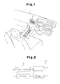
Fig. 1 is a perspective view illustrating an example of a touchpad and a display installed in a vehicle; -
Fig. 2 is a schematic block diagram illustrating a first embodiment of a touch type input device; -
Fig. 3 is a schematic front view illustrating the display for the touch type input device ofFig. 2 ; -
Fig. 4A is a front view of the display illustrated inFig. 3 when operational coordinates are moved to the center of an icon after waiting for a fixed time; -
Fig. 4B is a front view of the display illustrated inFig. 3 when operational coordinates are moved to the center of an icon without waiting for a fixed time; -
Fig. 5 is a schematic flowchart of a process performed by a controller illustrated inFig. 2 ; -
Fig. 6 is a schematic front view illustrating a display in a second embodiment; -
Fig. 7A is a front view of the display illustrated inFig. 6 when operational coordinates are moved to the center of an icon after waiting for a fixed time from when a touch-release operation is performed; -
Fig. 7B is a front view of the display illustrated inFig. 6 when moving operational coordinates to the center of an icon at the same time as when a touch-release operation is performed; and -
Fig. 8 is a schematic front view illustrating a display of a touch type input device in the prior art. - A first embodiment of a touch type input device will now be described with reference to
Figs. 1 to 5 . - Referring to
Fig. 1 , adisplay 5 is fitted into a central portion (center console) of adashboard 1. Ashift lever 3 is arranged on the center console 2. Atouchpad 13 is arranged near theshift lever 3. Thetouchpad 13 includes an exposed surface defining an operation surface. - A user touches (swipes) the
touchpad 13 to select icons shown on thedisplay 5 and make decisions. This allows for in-vehicle devices, such as a car navigation system, to be operated. - Referring to
Fig. 2 , a touchtype input device 10 includes thedisplay 5, thetouchpad 13, and acontroller 11. - The
touchpad 13 incorporates atouch sensor 14. Thetouch sensor 14 detects changes in the electrostatic capacitance when a finger contacts thetouchpad 13, and outputs the detection result to thecontroller 11. Thetouch sensor 14 is one example of a detector. - The
controller 11 includes atimer 11a that measures time. Thecontroller 11 controls thedisplay 5. Referring toFig. 3 , thecontroller 11 shows, for example,icons 50a to 50f on thedisplay 5. - The
controller 11 movesoperational coordinates 61, which are indicated by the cross inFig. 3 , on thedisplay 5 based on the detection result from thetouch sensor 14. Thecontroller 11 is capable of moving theoperational coordinates 61 in accordance with the direction and distance thetouchpad 13 is swiped. - Hypothetical boundary lines L1 to L3, which are indicated by broken lines in
Fig. 3 , are drawn between theicons 50a to 50f. The boundary lines L1 to L3 partitions thedisplay 5 intoregions 51a to 51f corresponding to theicons 50a to 50f, respectively. Thecontroller 11 determines which one of theregions 51a to 51f theoperational coordinates 61 are located in and selects the one of theicons 50a to 50f corresponding to the region where theoperational coordinates 61 are located. - The
controller 11 determines whether or not a touch-release operation has been performed based on the detection result of thetouch sensor 14. The touch-release operation is performed by separating a finger from thetouchpad 13, that is, by cancelling the touching of thetouchpad 13. After thetimer 11a measures a fixed time T1 from when thecontroller 11 determines that a touch-release operation has been performed, thecontroller 11 moves theoperational coordinates 61 to the center Pc of the selected icon (inFig. 3 ,icon 50a). Further, thecontroller 11 continues to keep the icon selected even after the touch-release operation. In this manner, one of the icons is always selected regardless of where theoperational coordinates 61 are located on thedisplay 5. Theoperational coordinates 61 are not shown on thedisplay 5. - For example, as illustrated in
Fig. 3 , when theoperational coordinates 61 are located at position P1 inregion 51a when a touch-release operation is performed, theoperational coordinates 61 move to the center Pc of theicon 50a after the fixed time T1 elapses. In the same manner, when theoperational coordinates 61 are located at position P2 inregion 51a when a touch-release operation is performed, theoperational coordinates 61 move to the center Pc of theicon 50a after the fixed time T1 elapses. By moving theoperational coordinates 61 to the center Pc of theicon 50a in such a manner, the swiping distance D1 is always constant when switching the selected icon to, for example,icon 50f. In the same manner, the swiping distance D2 is always constant when switching the selected icon to, for example,icon 50b. - The fixed time T1 is set to be within a time during which successive swiping operations may be expected to be performed. Successive swiping operations refer to the repetition of swiping operations and touch-release operations performed within a short period of time to switch the selected icon. For example, as illustrated in
Fig. 4A , to switch the selected icon fromicon 50a toicon 50f, successive swiping operations may be performed (e.g., two successive swiping operations S1 and S2). In this case, after the first swiping operation (and touch-release operation), theoperational coordinates 61 are not moved to the center Pc until the fixed time T1 elapses. Thus, even when a touch-release operation is performed after a first swiping operation, a second swiping operation may be successively performed to switch the selected ion fromicon 50a toicon 50f. When not waiting for the fixed time T1 to elapse, as illustrated inFig. 4B , after the first swiping operation S1, theoperational coordinates 61 are immediately returned to the center Pc of theicon 50a. This may make it difficult to switch the selected icon through successive swipes. - The process performed by
controller 11 will now be performed with reference to the flowchart ofFig. 5 . The process of the flowchart is repetitively performed. - The
controller 11 determines whether or not a touch-release operation has been performed (S101). When a touch-release operation has been performed (YES in S101), thecontroller 11 starts to measure time with thetimer 11a (S102). - Then, the
controller 11 determines whether or not the measured time has reached the fixed time T1 (S103). When the measured time reaches the fixed time T1 (YES in S103), thecontroller 11 moves theoperational coordinates 61 to the center Pc of the presently selected icon (S104). Then, thecontroller 11 resets thetimer 11a. - The first embodiment has the advantages described below.
- (1) When a touch-release operation is performed indicating that fingers have been separated from the
touchpad 13, thecontroller 11 moves theoperational coordinates 61 to a specified position in the region where theoperational coordinates 61 are located. For example, the specified position is the center Pc of the icon corresponding to the region in which theoperational coordinates 61 are located. Thus, the swiping distance from the center Pc of the presently selected icon is constant when the user switches the selected icon. This improves the operability of the touchtype input device 10. - (2) When the fixed time T1 elapses after a touch-release operation is performed, the
controller 11 moves theoperational coordinates 61 to the center Pc of the selected icon. Thus, when successive swiping operations are performed, theoperational coordinates 61 are not returned to the center Pc each time a swiping operation ends. Accordingly, the selected icon may be smoothly switched. This further improves the operability of the touchtype input device 10. - (3) The operational coordinates 61 are moved to the center Pc of the selected icon when the fixed time T1 elapses after a touch-release operation is performed. Thus, the
operational coordinates 61 are not stopped near the boundary lines L1 to L3 that partition theregions 51a to 51f. f. Further, since theoperational coordinates 61 are moved to the center Pc of the selected icon, theoperational coordinates 61 do not move across the boundary lines L1 to L3 when the user does not intend to do so. This avoids undesirable switching of selected icons. - A second embodiment of a touch type input device will now be described with reference to
Figs. 6 and7 . The following description focuses on differences from the first embodiment. - If the selected icon is switched during a period between when a touch-initiating operation is performed to when a touch-release operation is performed, the
controller 11 moves theoperational coordinates 61 to the center Pc of the selected icon at the same time as when the touch-release operation is performed. - For example, referring to
Fig. 6 , theoperational coordinates 61 may be located at position P11 inicon 50f when a user performs a touch-initiating operation, which indicates that the touching of thetouchpad 13 has been initiated. In this case, thetouchpad 13 may then be swiped to move theoperational coordinates 61 from position P11 to position P12, which is inicon 50a. When the user performs a touch-release operation on thetouchpad 13 by releasing his or her finger from position P12, theoperational coordinates 61 are simultaneously moved to the center Pc of theicon 50a. -
Figs. 7A and 7B illustrates an example of thedisplay 5 includingicons 71 to 76. When sequentially switching the selected icons in the order oficons 71 to 76, successive swiping operations may be performed at constant swiping distances D11 without waiting for the fixed time T1 to elapse.Fig. 7A illustrates a case in which the control of the first embodiment is executed, andFig. 7B illustrates a case in which the control of the second embodiment is executed. In bothFigs. 7A and 7B , the first swiping operation is performed over distance D11 to switch the selected icon fromicon 71 toicon 72. - However, referring to
Fig. 7A , in the control of the first embodiment, when a second swiping operation is successively performed over the same distance D11, theoperational coordinates 61 are moved from icon 72 (location of first touch-release operation) toicon 74 skippingicon 73. Accordingly, the selected icon is not switched toicon 73, which is the target of selection, andicon 74 is selected instead. - Referring to
Fig. 7B , in the control of the second embodiment, theoperational coordinates 61 are moved to the center Pc oficon 72 after the first swiping operation. Thus, even when the second swiping operation is successively performed over the same distance D11, theoperational coordinates 61 move from the center Pc oficon 72. Thus, theoperational coordinates 61 do not reachicon 74 and move toicon 73. Accordingly, when swiping operations are successively performed over the same distance D11, the selected icon may be correctly switched fromicon 72 toicon 73, which is the target of selection. - The second embodiment has the advantages described below.
- (4) When the selected icon is switched among
icons 50a to 50f between a touch-initiating operation and a touch-release operation, theoperational coordinates 61 are moved to the center Pc of the selected icon at the same time as when the touch-release operation is performed. Thus, when the selected icon is switched, the next swiping operation may be performed from the center Pc of the selected icon even before the fixed time T1 elapses from when a touch-release operation is performed. As a result, when successively switching the selected icons, swiping operations are performed over the same swiping distance. This improves the operability of the touchtype input device 10. - (5) When the selected icon is not switched between a touch-initiating operation and a touch-release operation, the advantages of the first embodiment are obtained.
- It should be apparent to those skilled in the art that the present invention may be embodied in many other specific forms without departing from the spirit or scope of the invention. Particularly, it should be understood that the present invention may be embodied in the following forms.
- In the first embodiment, when the fixed time T1 elapses after a touch-release operation, the
operational coordinates 61 are moved to the center Pc of the selected icon. However, the location (specified position) to where theoperational coordinates 61 are moved may be anywhere in the region were theoperational coordinates 61 are located when the touch-release operation is performed. In this case, theoperational coordinates 61 are located at the same position (specified position) when a swiping operation is performed again. Thus, the swiping distance is constant when switching the selected icon. The same applies to the second embodiment. More specifically, when the selected icon is switched during a period between a touch-initiating operation and a touch-release operation, theoperational coordinates 61 may be moved to a specified position other than the center Pc of the selected icon at the same time as when a touch-release operation is performed. - In the first embodiment, when the first time T1 elapses after a touch-release operation, the
operational coordinates 61 are moved to the center Pc of the selected icon (icon in the region where the presentoperational coordinates 61 are located). However, if theoperational coordinates 61 are not located in any of theregions 51a to 51f (i.e., none of theicons 50a to 50f are selected) when a touch-release operation is performed, theoperational coordinates 61 may be moved to the center Pc of the closest icon when a touch-release operation is performed. In this manner, the specified position to where theoperational coordinates 61 are moved may be the center of the selected icon when a touch-release operation is performed or the center of the icon closest to theoperational coordinates 61 when a touch-release operation is performed. The same applies to the second embodiment. - In the first embodiment, when the fixed time T1 elapses after a touch-release operation, the location of the
operational coordinates 61 moves to the center of the selected icon. Instead, theoperational coordinates 61 may immediately be moved to the center Pc of the selected icon without waiting for the fixed time T1 to elapse. This also allows the selected icon to be switched after a touch-release operation by swiping thetouchpad 13 over a distance that is always constant. - In each of the above embodiments, the
icons 50a to 50f and therespective regions 51a to 51f may span over the same areas. - The location of the
touchpad 13 is not limited to that of the above embodiments. For example, thetouchpad 13 may be arranged on the steering wheel or thedashboard 1. - The touch
type input device 10 of each of the above embodiments may be applied to an electric device other than a vehicle. - In each of the above embodiments, the
touch sensor 14 is of an electrostatic capacitance type. Instead, thetouch sensor 14 may be of a resistive film type, a surface acoustic wave type, an infrared type, or an electromagnetic induction type. - In each of the above embodiments, the type, number, and shape of the
icons 50a to 50f are not limited. - In each of the above embodiments, the
operational coordinates 61 are not shown on thedisplay 5. However, theoperational coordinates 61 may be shown as a pointer on thedisplay 5. - In each of the above embodiments, the concept of an icon includes a button, a list, and a scroll bar.
- The present examples and embodiments are to be considered as illustrative and not restrictive, and the invention is not to be limited to the details given herein, but may be modified within the scope and equivalence of the appended claims.
- A touch type input device (10) includes a display (5) capable of showing a plurality of icons (50a-50d). A detector (14) detects touching of an operation surface (13). A controller (11) moves operational coordinates (61) on the display (5) based on the detection of the detector (14). The controller (11) selects one of the icons (50a-50d) in accordance with a region in which the operational coordinates (61) are located. Further, the controller (11) moves the operational coordinates (61) to a specified position (Pc) in the region where the operational coordinates (61) are located when a touch-release operation is performed indicating that the touching of the operation surface (13) has been cancelled.
Claims (6)
- A touch type input device (10) comprising:a display (5) capable of showing a plurality of icons (50a-50d);a detector (14) configured to detect touching of an operation surface (13); anda controller (11) configured to move operational coordinates (61) on the display (5) based on the detection of the detector (14), wherein the controller (11) is configured to select one of the icons (50a-50d) in accordance with a region in which the operational coordinates (61) are located, the touch type input device (10) characterized in thatthe controller (11) is configured to move the operational coordinates (61) to a specified position (Pc) in the region where the operational coordinates (61) are located when a touch-release operation is performed indicating that the touching of the operation surface (13) has been cancelled.
- The touch type input device (10) according to claim 1, wherein the specified position (Pc) is a center of an icon that is selected when the touch-release operation is performed or a center of an icon that is closest to the operational coordinates (61) when the touch-release operation is performed.
- The touch type input device (10) according to claim 1, wherein the controller (11) is configured to move the operational coordinates (61) to the specified position (Pc) when a fixed time (T1) elapses after the touch-release operation is performed, and the fixed time (T1) allows for successive swiping operations (S1, S2) to be performed.
- The touch type input device (10) according to claim 3, wherein when the controller (11) determines that a selected icon has been switched during a period from when the touching of the operation surface (13) is started to when the touch-release operation is performed, the controller (11) is adapted to move the operational coordinates (61) to the specified position (Pc) simultaneously with when the touch-release operation is performed.
- The touch type input device (10) according to claim 1, further comprising a touchpad (13) arranged separately from the display (5), wherein the operation surface (13) is arranged on the touchpad (13).
- A vehicle comprising the touch type input device (10) according to claim 1.
Applications Claiming Priority (2)
| Application Number | Priority Date | Filing Date | Title |
|---|---|---|---|
| JP2012236525 | 2012-10-26 | ||
| JP2012281583A JP5689867B2 (en) | 2012-10-26 | 2012-12-25 | Touch input device |
Publications (2)
| Publication Number | Publication Date |
|---|---|
| EP2725475A2 true EP2725475A2 (en) | 2014-04-30 |
| EP2725475A3 EP2725475A3 (en) | 2017-12-20 |
Family
ID=49485504
Family Applications (1)
| Application Number | Title | Priority Date | Filing Date |
|---|---|---|---|
| EP13189618.5A Withdrawn EP2725475A3 (en) | 2012-10-26 | 2013-10-22 | Touch type input device |
Country Status (4)
| Country | Link |
|---|---|
| US (1) | US9223428B2 (en) |
| EP (1) | EP2725475A3 (en) |
| JP (1) | JP5689867B2 (en) |
| CN (1) | CN103793168B (en) |
Cited By (1)
| Publication number | Priority date | Publication date | Assignee | Title |
|---|---|---|---|---|
| EP3200056A4 (en) * | 2014-12-25 | 2017-11-15 | Aisin AW Co., Ltd. | Display control system, method, and program |
Families Citing this family (6)
| Publication number | Priority date | Publication date | Assignee | Title |
|---|---|---|---|---|
| CN105552561A (en) * | 2012-12-21 | 2016-05-04 | 株式会社村田制作所 | Interface unit and computer |
| JP5563698B1 (en) | 2013-05-10 | 2014-07-30 | 株式会社東海理化電機製作所 | Touch input device |
| CN106325678A (en) * | 2016-08-25 | 2017-01-11 | Tcl移动通信科技(宁波)有限公司 | Method and system for identifying icon of mobile terminal based on touch screen |
| JP6558380B2 (en) * | 2017-01-23 | 2019-08-14 | トヨタ自動車株式会社 | VEHICLE INPUT DEVICE, INPUT DEVICE, AND CONTROL METHOD FOR VEHICLE INPUT DEVICE |
| JP2018128968A (en) * | 2017-02-10 | 2018-08-16 | トヨタ自動車株式会社 | VEHICLE INPUT DEVICE AND CONTROL METHOD FOR VEHICLE INPUT DEVICE |
| CN112558803A (en) * | 2019-09-26 | 2021-03-26 | 北京钛方科技有限责任公司 | Vehicle-mounted touch device, control method and automobile |
Citations (1)
| Publication number | Priority date | Publication date | Assignee | Title |
|---|---|---|---|---|
| JP2009253773A (en) | 2008-04-08 | 2009-10-29 | Sharp Corp | Display system, remote control unit, display apparatus, control method of remote control unit, and control method of display apparatus |
Family Cites Families (14)
| Publication number | Priority date | Publication date | Assignee | Title |
|---|---|---|---|---|
| JPH05173714A (en) * | 1991-12-20 | 1993-07-13 | Sony Corp | Display device |
| JPH10240447A (en) * | 1997-03-03 | 1998-09-11 | Sony Corp | Pointing device and pointer control method |
| US6031531A (en) * | 1998-04-06 | 2000-02-29 | International Business Machines Corporation | Method and system in a graphical user interface for facilitating cursor object movement for physically challenged computer users |
| JP2003150317A (en) * | 2001-11-09 | 2003-05-23 | Mitsubishi Electric Corp | Display device and display method thereof |
| JP2006244393A (en) * | 2005-03-07 | 2006-09-14 | Tokai Rika Co Ltd | Input device |
| GB0523512D0 (en) * | 2005-11-18 | 2005-12-28 | Applied Generics Ltd | Enhancing traffic and navigation information with visual and audio data |
| CN101460919B (en) * | 2006-06-05 | 2012-04-18 | 三菱电机株式会社 | Display device and limited operation method of the device |
| JP4924164B2 (en) * | 2007-04-09 | 2012-04-25 | パナソニック株式会社 | Touch input device |
| JP4678534B2 (en) * | 2007-06-07 | 2011-04-27 | ソニー株式会社 | Navigation device and map scroll processing method |
| US8482521B2 (en) * | 2007-10-05 | 2013-07-09 | Gvbb Holdings S.A.R.L. | Pointer controlling apparatus |
| KR20100078366A (en) * | 2008-12-30 | 2010-07-08 | 삼성전자주식회사 | Method for providing gui including pointer representing visual effect moved by gravity and electronic device thereof |
| US8595645B2 (en) * | 2010-03-11 | 2013-11-26 | Apple Inc. | Device, method, and graphical user interface for marquee scrolling within a display area |
| KR101690595B1 (en) * | 2010-09-01 | 2016-12-28 | 엘지전자 주식회사 | Mobile Terminal And Method Of Managing Icon Using The Same |
| JP5381945B2 (en) * | 2010-09-21 | 2014-01-08 | アイシン・エィ・ダブリュ株式会社 | Touch panel type operation device, touch panel operation method, and computer program |
-
2012
- 2012-12-25 JP JP2012281583A patent/JP5689867B2/en not_active Expired - Fee Related
-
2013
- 2013-10-11 US US14/051,987 patent/US9223428B2/en not_active Expired - Fee Related
- 2013-10-21 CN CN201310496752.7A patent/CN103793168B/en not_active Expired - Fee Related
- 2013-10-22 EP EP13189618.5A patent/EP2725475A3/en not_active Withdrawn
Patent Citations (1)
| Publication number | Priority date | Publication date | Assignee | Title |
|---|---|---|---|---|
| JP2009253773A (en) | 2008-04-08 | 2009-10-29 | Sharp Corp | Display system, remote control unit, display apparatus, control method of remote control unit, and control method of display apparatus |
Cited By (2)
| Publication number | Priority date | Publication date | Assignee | Title |
|---|---|---|---|---|
| EP3200056A4 (en) * | 2014-12-25 | 2017-11-15 | Aisin AW Co., Ltd. | Display control system, method, and program |
| US10592014B2 (en) | 2014-12-25 | 2020-03-17 | Aisin Aw Co., Ltd. | Display control system, method, and program |
Also Published As
| Publication number | Publication date |
|---|---|
| JP2014102807A (en) | 2014-06-05 |
| CN103793168B (en) | 2017-08-08 |
| US20140118275A1 (en) | 2014-05-01 |
| US9223428B2 (en) | 2015-12-29 |
| CN103793168A (en) | 2014-05-14 |
| JP5689867B2 (en) | 2015-03-25 |
| EP2725475A3 (en) | 2017-12-20 |
Similar Documents
| Publication | Publication Date | Title |
|---|---|---|
| US9223428B2 (en) | Touch type input device | |
| JP5232889B2 (en) | Vehicle control device | |
| EP2751650B1 (en) | Interactive system for vehicle | |
| US9563311B2 (en) | Touch type input device and method for detecting touching of touch panel | |
| US9594472B2 (en) | Method and array for providing a graphical user interface, in particular in a vehicle | |
| JP5884742B2 (en) | User interface device and input acquisition method | |
| EP3182255A1 (en) | Touch-type input device | |
| EP2998840B1 (en) | Capacitive touch sensor device and controller | |
| EP2584436A1 (en) | Information display device and method for moving operation of onscreen button | |
| EP2960757A1 (en) | Touch-type input device | |
| WO2013029257A1 (en) | Vehicle's interactive system | |
| CN115129221B (en) | Operation input device, operation input method, and computer-readable medium having operation input program recorded thereon | |
| WO2015136348A1 (en) | Operating device for vehicle | |
| CN109710083A (en) | Input system | |
| CN114556271A (en) | Method and device for activating a cleaning mode of a touch-sensitive control panel | |
| KR101422060B1 (en) | Information display apparatus and method for vehicle using touch-pad, and information input module thereof | |
| CN115867455A (en) | Operating unit with touch-sensitive operating surface | |
| CN105378602B (en) | Method for operating input device and input device | |
| US9804744B2 (en) | Method for operating a control device in a vehicle | |
| EP3361367A1 (en) | In-vehicle input device, in-vehicle input system, and in-vehicle input device control method | |
| US20170255326A1 (en) | Vehicular touch pad and vehicular input interface | |
| JP2016115121A (en) | Vehicle operation apparatus | |
| JP6001463B2 (en) | Touch input device | |
| WO2018173179A1 (en) | Touch input determination device, touch panel input device, touch input determination method, and touch input determination program | |
| JP2016139234A (en) | Input control device |
Legal Events
| Date | Code | Title | Description |
|---|---|---|---|
| PUAI | Public reference made under article 153(3) epc to a published international application that has entered the european phase |
Free format text: ORIGINAL CODE: 0009012 |
|
| 17P | Request for examination filed |
Effective date: 20131022 |
|
| AK | Designated contracting states |
Kind code of ref document: A2 Designated state(s): AL AT BE BG CH CY CZ DE DK EE ES FI FR GB GR HR HU IE IS IT LI LT LU LV MC MK MT NL NO PL PT RO RS SE SI SK SM TR |
|
| AX | Request for extension of the european patent |
Extension state: BA ME |
|
| PUAL | Search report despatched |
Free format text: ORIGINAL CODE: 0009013 |
|
| AK | Designated contracting states |
Kind code of ref document: A3 Designated state(s): AL AT BE BG CH CY CZ DE DK EE ES FI FR GB GR HR HU IE IS IT LI LT LU LV MC MK MT NL NO PL PT RO RS SE SI SK SM TR |
|
| AX | Request for extension of the european patent |
Extension state: BA ME |
|
| RIC1 | Information provided on ipc code assigned before grant |
Ipc: G06F 3/0484 20130101ALI20171116BHEP Ipc: G06F 3/0488 20130101AFI20171116BHEP |
|
| STAA | Information on the status of an ep patent application or granted ep patent |
Free format text: STATUS: THE APPLICATION HAS BEEN WITHDRAWN |
|
| 18W | Application withdrawn |
Effective date: 20190703 |