EP2725421A1 - Illumination optical system and image projection device - Google Patents
Illumination optical system and image projection device Download PDFInfo
- Publication number
- EP2725421A1 EP2725421A1 EP20130186699 EP13186699A EP2725421A1 EP 2725421 A1 EP2725421 A1 EP 2725421A1 EP 20130186699 EP20130186699 EP 20130186699 EP 13186699 A EP13186699 A EP 13186699A EP 2725421 A1 EP2725421 A1 EP 2725421A1
- Authority
- EP
- European Patent Office
- Prior art keywords
- light
- lens unit
- optical system
- image
- unit
- Prior art date
- Legal status (The legal status is an assumption and is not a legal conclusion. Google has not performed a legal analysis and makes no representation as to the accuracy of the status listed.)
- Granted
Links
- 230000003287 optical effect Effects 0.000 title claims abstract description 44
- 238000005286 illumination Methods 0.000 title claims abstract description 16
- 238000010586 diagram Methods 0.000 description 6
- 230000008859 change Effects 0.000 description 2
- 230000004075 alteration Effects 0.000 description 1
- 238000010276 construction Methods 0.000 description 1
- 239000005357 flat glass Substances 0.000 description 1
- 238000003780 insertion Methods 0.000 description 1
- 230000037431 insertion Effects 0.000 description 1
- 238000009434 installation Methods 0.000 description 1
- 239000004973 liquid crystal related substance Substances 0.000 description 1
- 230000007246 mechanism Effects 0.000 description 1
- QSHDDOUJBYECFT-UHFFFAOYSA-N mercury Chemical compound [Hg] QSHDDOUJBYECFT-UHFFFAOYSA-N 0.000 description 1
- 229910052753 mercury Inorganic materials 0.000 description 1
- 238000000034 method Methods 0.000 description 1
- 238000012986 modification Methods 0.000 description 1
- 230000004048 modification Effects 0.000 description 1
- 230000008569 process Effects 0.000 description 1
- 239000011347 resin Substances 0.000 description 1
- 229920005989 resin Polymers 0.000 description 1
Images


Classifications
-
- G—PHYSICS
- G03—PHOTOGRAPHY; CINEMATOGRAPHY; ANALOGOUS TECHNIQUES USING WAVES OTHER THAN OPTICAL WAVES; ELECTROGRAPHY; HOLOGRAPHY
- G03B—APPARATUS OR ARRANGEMENTS FOR TAKING PHOTOGRAPHS OR FOR PROJECTING OR VIEWING THEM; APPARATUS OR ARRANGEMENTS EMPLOYING ANALOGOUS TECHNIQUES USING WAVES OTHER THAN OPTICAL WAVES; ACCESSORIES THEREFOR
- G03B21/00—Projectors or projection-type viewers; Accessories therefor
- G03B21/14—Details
- G03B21/142—Adjusting of projection optics
-
- G—PHYSICS
- G02—OPTICS
- G02B—OPTICAL ELEMENTS, SYSTEMS OR APPARATUS
- G02B7/00—Mountings, adjusting means, or light-tight connections, for optical elements
- G02B7/02—Mountings, adjusting means, or light-tight connections, for optical elements for lenses
- G02B7/026—Mountings, adjusting means, or light-tight connections, for optical elements for lenses using retaining rings or springs
-
- G—PHYSICS
- G03—PHOTOGRAPHY; CINEMATOGRAPHY; ANALOGOUS TECHNIQUES USING WAVES OTHER THAN OPTICAL WAVES; ELECTROGRAPHY; HOLOGRAPHY
- G03B—APPARATUS OR ARRANGEMENTS FOR TAKING PHOTOGRAPHS OR FOR PROJECTING OR VIEWING THEM; APPARATUS OR ARRANGEMENTS EMPLOYING ANALOGOUS TECHNIQUES USING WAVES OTHER THAN OPTICAL WAVES; ACCESSORIES THEREFOR
- G03B21/00—Projectors or projection-type viewers; Accessories therefor
- G03B21/14—Details
- G03B21/145—Housing details, e.g. position adjustments thereof
-
- G—PHYSICS
- G03—PHOTOGRAPHY; CINEMATOGRAPHY; ANALOGOUS TECHNIQUES USING WAVES OTHER THAN OPTICAL WAVES; ELECTROGRAPHY; HOLOGRAPHY
- G03B—APPARATUS OR ARRANGEMENTS FOR TAKING PHOTOGRAPHS OR FOR PROJECTING OR VIEWING THEM; APPARATUS OR ARRANGEMENTS EMPLOYING ANALOGOUS TECHNIQUES USING WAVES OTHER THAN OPTICAL WAVES; ACCESSORIES THEREFOR
- G03B21/00—Projectors or projection-type viewers; Accessories therefor
- G03B21/14—Details
- G03B21/20—Lamp housings
-
- H—ELECTRICITY
- H04—ELECTRIC COMMUNICATION TECHNIQUE
- H04N—PICTORIAL COMMUNICATION, e.g. TELEVISION
- H04N9/00—Details of colour television systems
- H04N9/12—Picture reproducers
- H04N9/31—Projection devices for colour picture display, e.g. using electronic spatial light modulators [ESLM]
Definitions
- the present invention relates to an illumination optical system and an image projection device.
- an image projection device that causes an image forming unit to generate an image to be projected by using a light emitted from a light source on the basis of image data received from a personal computer (PC) or a video camera, etc. and projects the generated image on a projection surface, such as a screen, to display the image on the projection surface.
- a projection surface such as a screen
- Such an image projection device is required to be capable of projecting an image on a large screen and reducing the distance between the image projection device and the projection surface as short as possible, and image projection devices enabling a short projection distance have been developed.
- a lens unit for expanding or compressing a light from a light source is arranged on a path of light from the light source to an image forming unit; therefore, the lens unit is required to be accurately fixed to an enclosure.
- a lens unit is fixed in such a way that the lens unit is inserted into a holding unit formed on an enclosure, and is pushed against the holding unit by a leaf spring member.
- an elastic member for pushing a lens unit in a direction of the optical axis and another elastic member for pushing the lens unit in a vertical direction are disposed.
- an illumination optical system and image projection device that are capable of fixing a lens unit located on a path of light from a light source to an image forming element with higher accuracy.
- an illumination optical system that includes a lens unit that is arranged on a path of an emitted light to an image forming element for forming an image; a holding unit that holds the lens unit; and an elastic body that is attached to the holding unit, and has integrally-formed first and second parts, the first part being biased in a direction of an optical axis of the light to press the lens unit, and the second part being biased in a direction perpendicular to the direction of the optical axis to press the lens unit.
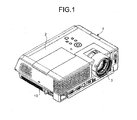
- FIG. 1 is a perspective view of a projector 1
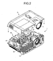
- FIG. 2 is a perspective view of the projector 1 with an upper cover 2 off.
- a projection lens 3 is attached to the upper cover 2.
- the projection lens 3 can change the magnification of video or image data to be eventually projected on a projection surface.
- an optical device 20, a light source device 30, a speaker unit 40, a housing unit 50, and an air intake unit 60 are arranged in a main body 10 composing an enclosure of the projector 1.
- FIG. 3 is a cross-sectional view illustrating the detailed configuration of the optical device 20 and the light source device 30.
- the optical device 20 includes an illumination optical system 20a and a projection system 20b.
- the optical device 20 further includes a color wheel 25, a light tunnel 26, relay lenses 27a and 27b, a flat mirror 28, and a concave mirror 29. These members are arranged in a main body of the optical device 20.
- an image forming unit 21 is arranged in the optical device 20.
- the image forming unit 21 includes digital micromirror devices (DMDs) serving as is an image forming device for forming an image.
- DMDs digital micromirror devices
- the disc-shaped color wheel 25 converts white light emitted from the light source device 30 into lights of red, green, and blue repeatedly per unit time, and outputs the converted light toward the light tunnel 26.
- the light tunnel 26 is formed into a cylindrical shape by bonding sheet glasses, and leads the light exiting from the color wheel 25 into a relay lens 27.
- the relay lens 27 is composed of a combination of the two relay lenses 27a and 27b which is a lens unit composed of a pair of lenses, and condenses the light output from the light tunnel 26 while correcting axial chromatic aberration of the light.
- the relay lens 27 is located on a path through which the light emitted from the light source device 30 is led to the image forming element that forms an image.
- the flat mirror 28 and the concave mirror 29 reflect the light output from the relay lens 27 and lead the reflected light into the image forming unit 21 so that the light is focused on the image forming unit 21.
- the image forming unit 21 includes digital micromirror devices (DMDs) having a rectangular mirror surface composed of multiple micromirrors, and processes a projecting light to form predetermined image data and reflects the processed light by driving the micromirrors in a time-division manner on the basis of video or image data.
- DMDs digital micromirror devices
- the light source device 30 includes, for example, a high-pressure mercury lamp as a light source.
- the light source device 30 emits a white light toward the illumination optical system 20a of the optical device 20.
- the white light emitted from the light source device 30 is separated into red, green, and blue lights (RGB), and the separated lights are led into the image forming unit 21.
- the image forming unit 21 forms an image according to a modulation signal, and the projection system 20b enlarges and projects the formed image.
- An OFF light plate is provided in an upper portion in the vertical direction of the image forming unit 21, that is, on the near side in Fig. 3 .
- the OFF light plate receives unwanted light not used as a projected light L out of the light entering the image forming unit 21.
- a plurality of micromirrors are activated by operations of the DMD in a time-division manner based on moving image data.
- the micromirrors reflect the light in use to the projector lens 3 and reflect the light to be discarded to the OFF light plate.
- the light used for a projected image is reflected to the projecting mechanism 20b, magnified through the projector lenses 3, whereby the magnified image light is projected.
- FIG. 4 is an explanatory diagram illustrating the arrangement and fixation of the relay lenses 27a and 27b viewed from the entrance side of a light.
- FIG. 5 is an explanatory diagram illustrating the arrangement and fixation of the relay lenses 27a and 27b viewed from the exit side of the light.
- FIG. 6 is an explanatory diagram illustrating the arrangement and fixation of the relay lenses 27a and 27b viewed from a direction perpendicular to the optical axis of the light.
- FIG. 7 illustrates the shape of an elastic member 70 for fixing the relay lens 27.
- the relay lenses 27a and 27b are arranged approximately parallel to a holding unit forming a housing of the relay lenses 27a and 27b so as to be coaxial with the optical axis of a light emitted from the light source device 30.
- the holding unit is composed of a holding unit 71 having a shape along the relay lens 27a and a holding unit 72 having a shape along the relay lens 27b.
- the holding unit 71 actually has a three-point contact with the relay lens 27a.
- the three contact points are contact portions 71a to 71c.
- the contact portion 71a comes into contact with an upper right portion of the relay lens 27a viewed from the side of the light source device 30.
- the contact portion 71b comes into contact with a lower end portion of the relay lens 27a viewed from the side of the light source device 30.
- the contact portion 71c comes into contact with an upper left portion of the relay lens 27a viewed from the side of the light source device 30.
- the contact portions 71a and 71c are linearly symmetric about a line passing through the optical axis. Therefore, the holding unit 71 is molded so that a portion of the holding unit 71 other than the contact portions 71a to 71c is cut out. Therefore, the cutout portion corresponds to a non-contact portion.
- the holding unit 72 also has contact portions 72a to 72c formed in the same way.
- the relay lenses 27a and 27b each have a convex curved surface and a flat surface; the curved surface is located on the exit side of a light, and the flat surface is located on the entrance side of the light. Therefore, in the present embodiment, the light-entrance-side surface of the relay lens 27a comes into contact with the contact portions 71a to 71c, and the light-entrance-side surface of the relay lens 27b comes into contact with the contact portions 72a to 72c.
- the elastic member 70 is inserted into a space formed by the holding units 71 and 72.
- the elastic member 70 is configured to fit with the shape of the holding units 71 and 72, and is fixed to the holding units 71 and 72 by the insertion.
- the elastic member 70 is formed of, for example, a leaf spring or an elastically-deformable resin member.
- the elastic member 70 includes presser parts 73 to 78.
- the presser part 73 (a first part) presses the relay lens 27a from the light exit side against the contact portion 71a, i.e., in a direction of the optical axis.
- the presser part 74 (the first part) presses the relay lens 27a from the light exit side against the contact portion 71c, i.e., in the direction of the optical axis.
- the presser part 75 (the first part) presses the relay lens 27b from the light exit side against the contact portion 72a, i.e., in the direction of the optical axis.
- the presser part 76 presses the relay lens 27b from the light exit side against the contact portion 72c, i.e., in the direction of the optical axis.
- the presser part 77 (a second part) presses the relay lens 27b obliquely downward from the top right of the relay lens 27b viewed from the light source device 30 against the contact portion 72b, i.e., in a direction perpendicular to the direction of the optical axis.
- the presser part 78 presses the relay lens 27a obliquely downward viewed from the light source device 30 against the contact portion 71b, i.e., in the direction perpendicular to the direction of the optical axis.
- the presser parts 77 and 78 are integrally formed in such a manner that the presser parts 77 and 78 branch from a single member.
- the elastic member 70 when arranging the relay lenses 27a and 27b in the main body 10, the elastic member 70 is first disposed. Then, the relay lens 27a is to be arranged in the holding unit 71; however, the presser parts 78, 73, and 74 of the elastic member 70 are biased to the side of the relay lens 27a, so the relay lens 27a is arranged in the holding unit 71 by pushing the presser parts 73, 74, and 78 aside by the relay lens 27a so as not to obstruct the arrangement. On completion of the arrangement, the presser parts 73, 74, and 78 pushed aside by the relay lens 27a try to return back to their original positions, and therefore the relay lens 27a is pressed against the contact portions 71a to 71c.
- the relay lens 27b is to be arranged in the holding unit 72; however, the presser parts 77, 75, and 76 of the elastic member 70 are biased to the side of the relay lens 27b, so the relay lens 27b is arranged in the holding unit 72 by pushing the presser parts 75, 76, and 77 aside by the relay lens 27b so as not to obstruct the arrangement.
- the presser parts 75, 76, and 77 pushed aside by the relay lens 27b try to return back to their original positions, and therefore the relay lens 27b is pressed against the contact portions 72a to 72c.
- the relay lenses 27a and 27b is pressed against the holding units 71 and 72 constituting the enclosure by the shared elastic member 70. Therefore, the relay lenses can be accurately fixed and positioned by a small number of parts. Furthermore, as the elastic member 70 is formed of one member, the elastic member 70 is stably fixed to the holding units 71 and 72 as compared with a case where an elastic member is separately formed, and can suppress a shift in fixation of the relay lenses 27a and 27b; therefore, it is possible to further increase the accuracy of fixation.
- the presser part 78 for pressing the relay lens 27a from the top of the relay lens 27a and the presser part 77 for pressing the relay lens 27b from the top of the relay lens 27b are formed as one part, and therefore the elastic member 70 can be more easily and accurately formed.
- the holding units 71 and 72 are configured to have contact with the light-entrance-side surfaces of the relay lenses 27a and 27b, respectively.
- the holding units 71 and 72 can be configured to have contact with the light-exit-side surfaces of the relay lenses 27a and 27b, respectively.
- the pressing direction of the elastic member 70 changes to an opposite direction, so it is necessary to change the shape of the elastic member 70 according to the positions of the holding units.
- the light-exit-side surfaces of the relay lenses 27a and 27b have the curved shape, and therefore, even if there is a slight misalignment of the relay lenses 27a and 27b, the influence of the misalignment can be suppressed on the light exit side than that on the light entrance side.
- the presser parts 78 and 77 of the elastic member 70 are configured to press the relay lenses 27a and 27b obliquely downward, thereby applying both a downward vector and a transverse vector to the relay lenses 27a and 27b; however, the presser parts 78 and 77 only have to be configured to apply at least a downward vector to the relay lenses 27a and 27b. Furthermore, the presser parts 77 and 78 do not have to be formed of a single member.
- both of the relay lenses 27a and 27b do not always have to be installed; alternatively, the relay lens 27 can be composed of one relay lens.
- the present invention it is possible to fix a lens unit located on a path of light from a light source to an image forming element with higher accuracy.
Landscapes
- Physics & Mathematics (AREA)
- General Physics & Mathematics (AREA)
- Optics & Photonics (AREA)
- Engineering & Computer Science (AREA)
- Multimedia (AREA)
- Signal Processing (AREA)
- Projection Apparatus (AREA)
- Transforming Electric Information Into Light Information (AREA)
Abstract
Description
- The present invention relates to an illumination optical system and an image projection device.
- Conventionally, there is known an image projection device that causes an image forming unit to generate an image to be projected by using a light emitted from a light source on the basis of image data received from a personal computer (PC) or a video camera, etc. and projects the generated image on a projection surface, such as a screen, to display the image on the projection surface. Such an image projection device is required to be capable of projecting an image on a large screen and reducing the distance between the image projection device and the projection surface as short as possible, and image projection devices enabling a short projection distance have been developed.
- In an image projection device, a lens unit for expanding or compressing a light from a light source is arranged on a path of light from the light source to an image forming unit; therefore, the lens unit is required to be accurately fixed to an enclosure. For example, in an image projection device disclosed in Japanese Patent Application Laid-open No.
2005-266702 2004-117931 - However, in the image projection devices enabling a short projection distance, a slight misalignment of the lens unit causes a large projection error; therefore, the fixation of the lens unit as described above is required to be performed with higher accuracy.
- Therefore, there is a need for an illumination optical system and image projection device that are capable of fixing a lens unit located on a path of light from a light source to an image forming element with higher accuracy.
- According to an embodiment, there is provided an illumination optical system that includes a lens unit that is arranged on a path of an emitted light to an image forming element for forming an image; a holding unit that holds the lens unit; and an elastic body that is attached to the holding unit, and has integrally-formed first and second parts, the first part being biased in a direction of an optical axis of the light to press the lens unit, and the second part being biased in a direction perpendicular to the direction of the optical axis to press the lens unit.
- The above and other objects, features, advantages and technical and industrial significance of this invention will be better understood by reading the following detailed description of presently preferred embodiments of the invention, when considered in connection with the accompanying drawings.
-
-
FIG. 1 is a perspective view of a projector according to an embodiment; -
FIG. 2 is a perspective view of the projector with an upper cover off; -
FIG. 3 is a cross-sectional view of an optical device and a light source device according to the embodiment; -
FIG. 4 is an explanatory diagram illustrating the arrangement and fixation of a pair of relay lenses according to the embodiment viewed from the entrance side of a light; -
FIG. 5 is an explanatory diagram illustrating the arrangement and fixation of the pair of relay lenses viewed from the exit side of the light; -
FIG. 6 is an explanatory diagram illustrating the arrangement and fixation of the pair of relay lenses viewed from a direction perpendicular to the optical axis of the light; and -
FIG. 7 is a perspective view of an elastic member according to the embodiment. - An exemplary embodiment of a projector as an example of an image projection device according to the present invention will be explained below with reference to accompanying drawings. The present invention can be applied to other electronic devices that include a speaker and are required to suppress vibration, and can be applied to, for example, a PC and a TV, etc.
FIG. 1 is a perspective view of a projector 1, andFIG. 2 is a perspective view of the projector 1 with anupper cover 2 off. - As illustrated in
FIGS. 1 and2 , aprojection lens 3 is attached to theupper cover 2. Theprojection lens 3 can change the magnification of video or image data to be eventually projected on a projection surface. Furthermore, anoptical device 20, alight source device 30, aspeaker unit 40, ahousing unit 50, and anair intake unit 60 are arranged in amain body 10 composing an enclosure of the projector 1. -
FIG. 3 is a cross-sectional view illustrating the detailed configuration of theoptical device 20 and thelight source device 30. As illustrated inFIG. 3 , theoptical device 20 includes an illuminationoptical system 20a and aprojection system 20b. Theoptical device 20 further includes acolor wheel 25, alight tunnel 26,relay lenses flat mirror 28, and aconcave mirror 29. These members are arranged in a main body of theoptical device 20. Furthermore, animage forming unit 21 is arranged in theoptical device 20. Theimage forming unit 21 includes digital micromirror devices (DMDs) serving as is an image forming device for forming an image. - The disc-
shaped color wheel 25 converts white light emitted from thelight source device 30 into lights of red, green, and blue repeatedly per unit time, and outputs the converted light toward thelight tunnel 26. Thelight tunnel 26 is formed into a cylindrical shape by bonding sheet glasses, and leads the light exiting from thecolor wheel 25 into arelay lens 27. Therelay lens 27 is composed of a combination of the tworelay lenses light tunnel 26 while correcting axial chromatic aberration of the light. Therelay lens 27 is located on a path through which the light emitted from thelight source device 30 is led to the image forming element that forms an image. Theflat mirror 28 and theconcave mirror 29 reflect the light output from therelay lens 27 and lead the reflected light into theimage forming unit 21 so that the light is focused on theimage forming unit 21. Theimage forming unit 21 includes digital micromirror devices (DMDs) having a rectangular mirror surface composed of multiple micromirrors, and processes a projecting light to form predetermined image data and reflects the processed light by driving the micromirrors in a time-division manner on the basis of video or image data. - The
light source device 30 includes, for example, a high-pressure mercury lamp as a light source. Thelight source device 30 emits a white light toward the illuminationoptical system 20a of theoptical device 20. In the illuminationoptical system 20a, the white light emitted from thelight source device 30 is separated into red, green, and blue lights (RGB), and the separated lights are led into theimage forming unit 21. Then, theimage forming unit 21 forms an image according to a modulation signal, and theprojection system 20b enlarges and projects the formed image. - An OFF light plate is provided in an upper portion in the vertical direction of the
image forming unit 21, that is, on the near side inFig. 3 . The OFF light plate receives unwanted light not used as a projected light L out of the light entering theimage forming unit 21. When light enters theimage forming unit 21, a plurality of micromirrors are activated by operations of the DMD in a time-division manner based on moving image data. The micromirrors reflect the light in use to theprojector lens 3 and reflect the light to be discarded to the OFF light plate. In theimage forming unit 21, the light used for a projected image is reflected to theprojecting mechanism 20b, magnified through theprojector lenses 3, whereby the magnified image light is projected. - Subsequently, the structure of installation of the
relay lens 27 in themain body 10 is explained with reference toFIGS. 4 to 7 .FIG. 4 is an explanatory diagram illustrating the arrangement and fixation of therelay lenses FIG. 5 is an explanatory diagram illustrating the arrangement and fixation of therelay lenses FIG. 6 is an explanatory diagram illustrating the arrangement and fixation of therelay lenses FIG. 7 illustrates the shape of anelastic member 70 for fixing therelay lens 27. - As illustrated in
FIGS. 4 to 6 , therelay lenses relay lenses light source device 30. The holding unit is composed of aholding unit 71 having a shape along therelay lens 27a and aholding unit 72 having a shape along therelay lens 27b. Theholding unit 71 actually has a three-point contact with therelay lens 27a. The three contact points arecontact portions 71a to 71c. Thecontact portion 71a comes into contact with an upper right portion of therelay lens 27a viewed from the side of thelight source device 30. Thecontact portion 71b comes into contact with a lower end portion of therelay lens 27a viewed from the side of thelight source device 30. Thecontact portion 71c comes into contact with an upper left portion of therelay lens 27a viewed from the side of thelight source device 30. Thecontact portions holding unit 71 is molded so that a portion of theholding unit 71 other than thecontact portions 71a to 71c is cut out. Therefore, the cutout portion corresponds to a non-contact portion. Furthermore, the holdingunit 72 also hascontact portions 72a to 72c formed in the same way. - The
relay lenses relay lens 27a comes into contact with thecontact portions 71a to 71c, and the light-entrance-side surface of therelay lens 27b comes into contact with thecontact portions 72a to 72c. Theelastic member 70 is inserted into a space formed by the holdingunits elastic member 70 is configured to fit with the shape of the holdingunits units elastic member 70 is formed of, for example, a leaf spring or an elastically-deformable resin member. - As illustrated in
FIG. 7 , theelastic member 70 includespresser parts 73 to 78. The presser part 73 (a first part) presses therelay lens 27a from the light exit side against thecontact portion 71a, i.e., in a direction of the optical axis. The presser part 74 (the first part) presses therelay lens 27a from the light exit side against thecontact portion 71c, i.e., in the direction of the optical axis. The presser part 75 (the first part) presses therelay lens 27b from the light exit side against thecontact portion 72a, i.e., in the direction of the optical axis. The presser part 76 (the first part) presses therelay lens 27b from the light exit side against thecontact portion 72c, i.e., in the direction of the optical axis. The presser part 77 (a second part) presses therelay lens 27b obliquely downward from the top right of therelay lens 27b viewed from thelight source device 30 against thecontact portion 72b, i.e., in a direction perpendicular to the direction of the optical axis. The presser part 78 (the second part) presses therelay lens 27a obliquely downward viewed from thelight source device 30 against thecontact portion 71b, i.e., in the direction perpendicular to the direction of the optical axis. Thepresser parts presser parts - In the above-described configuration, when arranging the
relay lenses main body 10, theelastic member 70 is first disposed. Then, therelay lens 27a is to be arranged in the holdingunit 71; however, thepresser parts elastic member 70 are biased to the side of therelay lens 27a, so therelay lens 27a is arranged in the holdingunit 71 by pushing thepresser parts relay lens 27a so as not to obstruct the arrangement. On completion of the arrangement, thepresser parts relay lens 27a try to return back to their original positions, and therefore therelay lens 27a is pressed against thecontact portions 71a to 71c. - Then, the
relay lens 27b is to be arranged in the holdingunit 72; however, thepresser parts elastic member 70 are biased to the side of therelay lens 27b, so therelay lens 27b is arranged in the holdingunit 72 by pushing thepresser parts relay lens 27b so as not to obstruct the arrangement. On completion of the arrangement, thepresser parts relay lens 27b try to return back to their original positions, and therefore therelay lens 27b is pressed against thecontact portions 72a to 72c. - In the illumination optical system described above, a pair of the
relay lenses units elastic member 70. Therefore, the relay lenses can be accurately fixed and positioned by a small number of parts. Furthermore, as theelastic member 70 is formed of one member, theelastic member 70 is stably fixed to the holdingunits relay lenses - Moreover, the
presser part 78 for pressing therelay lens 27a from the top of therelay lens 27a and thepresser part 77 for pressing therelay lens 27b from the top of therelay lens 27b are formed as one part, and therefore theelastic member 70 can be more easily and accurately formed. - Furthermore, instead of holding the
relay lenses overall holding units units contact portions 71a to 71c and 72a to 72c of the holdingunits relay lenses - The holding
units relay lenses units relay lenses elastic member 70 changes to an opposite direction, so it is necessary to change the shape of theelastic member 70 according to the positions of the holding units. Furthermore, the light-exit-side surfaces of therelay lenses relay lenses - Moreover, the
presser parts elastic member 70 are configured to press therelay lenses relay lenses presser parts relay lenses presser parts - Moreover, there is described the configuration using the DMDs as an image forming element; however, other image forming elements, such as a liquid crystal element, can be used. Furthermore, both of the
relay lenses relay lens 27 can be composed of one relay lens. - According to the present invention, it is possible to fix a lens unit located on a path of light from a light source to an image forming element with higher accuracy.
- Although the invention has been described with respect to specific embodiments for a complete and clear disclosure, the appended claims are not to be thus limited but are to be construed as embodying all modifications and alternative constructions that may occur to one skilled in the art that fairly fall within the basic teaching herein set forth.
- The present application claims priority to and incorporates by reference the entire contents of Japanese Patent Application No.
2012-235824
Claims (6)
- An illumination optical system comprising:a lens unit that is arranged on a path of an emitted light to an image forming element for forming an image;a holding unit that holds the lens unit; andan elastic body that is attached to the holding unit, and has integrally-formed first and second parts, the first part being biased in a direction of an optical axis of the light to press the lens unit, and the second part being biased in a direction perpendicular to the direction of the optical axis to press the lens unit.
- The illumination optical system according to claim 1, wherein
the lens unit includes a pair of lenses, and
out of portions of the elastic body that presses the pair of lenses, portions that correspond to the pair of lenses and are biased in the direction perpendicular to the direction of the optical axis are formed on the same member. - The illumination optical system according to claim 1 or 2, wherein
the elastic body presses the lens unit from a light exit side of the lens unit against the holding unit in the direction of the optical axis of the light. - The illumination optical system according to claim 1, 2 or 3, wherein
the elastic body is biased in a obliquely downward direction toward the holding unit, to press the lens unit in the direction perpendicular to the direction of the optical axis. - The illumination optical system according to claim 1, 2, 3 or 4wherein
the holding unit includes a cutout non-contact portion not coming into contact with the lens unit and a contact portion coming into point contact with the lens unit. - An image projection device comprising:the illumination optical system according to any one of claims 1 to 5;a light source device that emits a light;an image forming unit that receives the light emitted from the light source device through the illumination optical system, and generates an image to be projected; anda projection lens that projects the generated image.
Applications Claiming Priority (1)
| Application Number | Priority Date | Filing Date | Title |
|---|---|---|---|
| JP2012235824A JP6107049B2 (en) | 2012-10-25 | 2012-10-25 | Illumination optical system and image projection apparatus |
Publications (2)
| Publication Number | Publication Date |
|---|---|
| EP2725421A1 true EP2725421A1 (en) | 2014-04-30 |
| EP2725421B1 EP2725421B1 (en) | 2017-11-08 |
Family
ID=49253208
Family Applications (1)
| Application Number | Title | Priority Date | Filing Date |
|---|---|---|---|
| EP13186699.8A Not-in-force EP2725421B1 (en) | 2012-10-25 | 2013-09-30 | Illumination optical system and image projection device |
Country Status (4)
| Country | Link |
|---|---|
| US (1) | US9104093B2 (en) |
| EP (1) | EP2725421B1 (en) |
| JP (1) | JP6107049B2 (en) |
| CN (1) | CN103777449B (en) |
Families Citing this family (5)
| Publication number | Priority date | Publication date | Assignee | Title |
|---|---|---|---|---|
| JP6119183B2 (en) * | 2012-10-19 | 2017-04-26 | セイコーエプソン株式会社 | projector |
| JP7013893B2 (en) * | 2018-01-30 | 2022-02-01 | セイコーエプソン株式会社 | Projection lens and projector |
| CN109597270A (en) * | 2019-01-28 | 2019-04-09 | 苏州佳世达光电有限公司 | Lens module, using the ray machine and projection arrangement for having the lens module |
| EP3825749A1 (en) | 2019-11-22 | 2021-05-26 | Ricoh Company, Ltd. | Optical-element angle adjustment device and image projection device |
| JP7274108B2 (en) * | 2021-05-14 | 2023-05-16 | カシオ計算機株式会社 | Optical member fixing device and projection device |
Citations (6)
| Publication number | Priority date | Publication date | Assignee | Title |
|---|---|---|---|---|
| JP2004117931A (en) | 2002-09-27 | 2004-04-15 | Seiko Epson Corp | projector |
| JP2005266702A (en) | 2004-03-22 | 2005-09-29 | Seiko Epson Corp | Optical component housing and projector |
| JP2007010980A (en) * | 2005-06-30 | 2007-01-18 | Konica Minolta Opto Inc | Mirror holding structure and projection optical device |
| US20070195441A1 (en) * | 2004-08-18 | 2007-08-23 | Mitsubishi Electric Corporation | Supporting Mechanism Of Reflector And Projection Apparatus |
| US20080094582A1 (en) * | 2006-10-19 | 2008-04-24 | Sanyo Electric Co., Ltd. | Projection type image display apparatus |
| US20100074284A1 (en) * | 2008-09-22 | 2010-03-25 | Mitsubishi Electric Corporation | Light source unit and image displaying apparatus using the same |
Family Cites Families (10)
| Publication number | Priority date | Publication date | Assignee | Title |
|---|---|---|---|---|
| JP4221787B2 (en) | 1998-10-20 | 2009-02-12 | 株式会社富士通ゼネラル | Condensing structure of condenser lens |
| JP4352284B2 (en) | 1999-01-22 | 2009-10-28 | ソニー株式会社 | Optical component holding device and projector device |
| JP2001154082A (en) | 1999-11-29 | 2001-06-08 | Matsushita Electric Ind Co Ltd | Mirror mounting structure |
| JP4101484B2 (en) | 2001-07-24 | 2008-06-18 | 株式会社日立製作所 | OPTICAL UNIT, OPTICAL UNIT MANUFACTURING METHOD, AND VIDEO DISPLAY DEVICE |
| KR100826189B1 (en) | 2006-06-09 | 2008-04-30 | 엘지전자 주식회사 | Lens assembly for optical engine |
| CN101533209B (en) | 2008-03-14 | 2012-02-01 | 三洋科技中心(深圳)有限公司 | Adjusting component of projector optical lens, projector optical engine and projector |
| JP5125700B2 (en) * | 2008-04-04 | 2013-01-23 | パナソニック株式会社 | Lens holding device and projection display device using the same |
| JP2011002700A (en) | 2009-06-19 | 2011-01-06 | Fujifilm Corp | Projector |
| JP5532772B2 (en) | 2009-09-09 | 2014-06-25 | 三菱電機株式会社 | Projection display |
| JP2010033089A (en) * | 2009-11-16 | 2010-02-12 | Sanyo Electric Co Ltd | Optical device and projection type image display device using the same |
-
2012
- 2012-10-25 JP JP2012235824A patent/JP6107049B2/en not_active Expired - Fee Related
-
2013
- 2013-09-26 US US14/037,578 patent/US9104093B2/en not_active Expired - Fee Related
- 2013-09-30 EP EP13186699.8A patent/EP2725421B1/en not_active Not-in-force
- 2013-10-22 CN CN201310501160.XA patent/CN103777449B/en not_active Expired - Fee Related
Patent Citations (6)
| Publication number | Priority date | Publication date | Assignee | Title |
|---|---|---|---|---|
| JP2004117931A (en) | 2002-09-27 | 2004-04-15 | Seiko Epson Corp | projector |
| JP2005266702A (en) | 2004-03-22 | 2005-09-29 | Seiko Epson Corp | Optical component housing and projector |
| US20070195441A1 (en) * | 2004-08-18 | 2007-08-23 | Mitsubishi Electric Corporation | Supporting Mechanism Of Reflector And Projection Apparatus |
| JP2007010980A (en) * | 2005-06-30 | 2007-01-18 | Konica Minolta Opto Inc | Mirror holding structure and projection optical device |
| US20080094582A1 (en) * | 2006-10-19 | 2008-04-24 | Sanyo Electric Co., Ltd. | Projection type image display apparatus |
| US20100074284A1 (en) * | 2008-09-22 | 2010-03-25 | Mitsubishi Electric Corporation | Light source unit and image displaying apparatus using the same |
Also Published As
| Publication number | Publication date |
|---|---|
| CN103777449B (en) | 2016-04-27 |
| US20140118706A1 (en) | 2014-05-01 |
| US9104093B2 (en) | 2015-08-11 |
| EP2725421B1 (en) | 2017-11-08 |
| JP2014085591A (en) | 2014-05-12 |
| JP6107049B2 (en) | 2017-04-05 |
| CN103777449A (en) | 2014-05-07 |
Similar Documents
| Publication | Publication Date | Title |
|---|---|---|
| US9104093B2 (en) | Illumination optical system and image projection device | |
| TWI230805B (en) | Lighting optical system and projector using the same | |
| EP2706757B1 (en) | Electronic device and image projection apparatus | |
| CN107003497A (en) | Projector optical apparatus and projecting apparatus | |
| US9690176B2 (en) | Projection optical apparatus and projector | |
| CN107621747A (en) | Optical devices and projecting apparatus | |
| US9110360B2 (en) | Image projection apparatus | |
| US12222636B2 (en) | Projection lens and projection device | |
| EP1942373A2 (en) | Projection type display apparatus and optical unit | |
| US8690356B2 (en) | Video display device and light guide module with a light shielding plate having a plurality of openings | |
| US20120092625A1 (en) | Projector | |
| US20120154758A1 (en) | Projection display device | |
| US9244247B2 (en) | Auto-focus device, projection lens device, and image projection apparatus | |
| US9335618B2 (en) | Projection image display apparatus | |
| US8068293B2 (en) | Projection lens unit | |
| CN113406847B (en) | projector | |
| EP3309595A1 (en) | Support for optical element and image drawing apparatus | |
| US8414129B2 (en) | Optical system | |
| KR20170004618A (en) | Optical engine of projector | |
| JP4780200B2 (en) | Lens frame, lens holding device, and projector | |
| JP2002350977A (en) | projector | |
| JP6098076B2 (en) | Image projection device | |
| JP2015184547A (en) | projector | |
| JP2016138959A (en) | Projection optical device and projector | |
| JP2010211158A (en) | Optical unit for projector device and projector device |
Legal Events
| Date | Code | Title | Description |
|---|---|---|---|
| PUAI | Public reference made under article 153(3) epc to a published international application that has entered the european phase |
Free format text: ORIGINAL CODE: 0009012 |
|
| 17P | Request for examination filed |
Effective date: 20130930 |
|
| AK | Designated contracting states |
Kind code of ref document: A1 Designated state(s): AL AT BE BG CH CY CZ DE DK EE ES FI FR GB GR HR HU IE IS IT LI LT LU LV MC MK MT NL NO PL PT RO RS SE SI SK SM TR |
|
| AX | Request for extension of the european patent |
Extension state: BA ME |
|
| REG | Reference to a national code |
Ref country code: DE Ref legal event code: R079 Ref document number: 602013029035 Country of ref document: DE Free format text: PREVIOUS MAIN CLASS: G03B0021140000 Ipc: G02B0007020000 |
|
| RIC1 | Information provided on ipc code assigned before grant |
Ipc: G03B 21/20 20060101ALI20170425BHEP Ipc: G03B 21/14 20060101ALI20170425BHEP Ipc: G02B 7/02 20060101AFI20170425BHEP |
|
| GRAP | Despatch of communication of intention to grant a patent |
Free format text: ORIGINAL CODE: EPIDOSNIGR1 |
|
| STAA | Information on the status of an ep patent application or granted ep patent |
Free format text: STATUS: GRANT OF PATENT IS INTENDED |
|
| INTG | Intention to grant announced |
Effective date: 20170612 |
|
| GRAS | Grant fee paid |
Free format text: ORIGINAL CODE: EPIDOSNIGR3 |
|
| GRAA | (expected) grant |
Free format text: ORIGINAL CODE: 0009210 |
|
| STAA | Information on the status of an ep patent application or granted ep patent |
Free format text: STATUS: THE PATENT HAS BEEN GRANTED |
|
| AK | Designated contracting states |
Kind code of ref document: B1 Designated state(s): AL AT BE BG CH CY CZ DE DK EE ES FI FR GB GR HR HU IE IS IT LI LT LU LV MC MK MT NL NO PL PT RO RS SE SI SK SM TR |
|
| REG | Reference to a national code |
Ref country code: GB Ref legal event code: FG4D |
|
| REG | Reference to a national code |
Ref country code: AT Ref legal event code: REF Ref document number: 944682 Country of ref document: AT Kind code of ref document: T Effective date: 20171115 Ref country code: CH Ref legal event code: EP |
|
| REG | Reference to a national code |
Ref country code: IE Ref legal event code: FG4D |
|
| REG | Reference to a national code |
Ref country code: DE Ref legal event code: R096 Ref document number: 602013029035 Country of ref document: DE |
|
| REG | Reference to a national code |
Ref country code: NL Ref legal event code: MP Effective date: 20171108 |
|
| REG | Reference to a national code |
Ref country code: LT Ref legal event code: MG4D |
|
| REG | Reference to a national code |
Ref country code: AT Ref legal event code: MK05 Ref document number: 944682 Country of ref document: AT Kind code of ref document: T Effective date: 20171108 |
|
| PG25 | Lapsed in a contracting state [announced via postgrant information from national office to epo] |
Ref country code: LT Free format text: LAPSE BECAUSE OF FAILURE TO SUBMIT A TRANSLATION OF THE DESCRIPTION OR TO PAY THE FEE WITHIN THE PRESCRIBED TIME-LIMIT Effective date: 20171108 Ref country code: ES Free format text: LAPSE BECAUSE OF FAILURE TO SUBMIT A TRANSLATION OF THE DESCRIPTION OR TO PAY THE FEE WITHIN THE PRESCRIBED TIME-LIMIT Effective date: 20171108 Ref country code: SE Free format text: LAPSE BECAUSE OF FAILURE TO SUBMIT A TRANSLATION OF THE DESCRIPTION OR TO PAY THE FEE WITHIN THE PRESCRIBED TIME-LIMIT Effective date: 20171108 Ref country code: NL Free format text: LAPSE BECAUSE OF FAILURE TO SUBMIT A TRANSLATION OF THE DESCRIPTION OR TO PAY THE FEE WITHIN THE PRESCRIBED TIME-LIMIT Effective date: 20171108 Ref country code: FI Free format text: LAPSE BECAUSE OF FAILURE TO SUBMIT A TRANSLATION OF THE DESCRIPTION OR TO PAY THE FEE WITHIN THE PRESCRIBED TIME-LIMIT Effective date: 20171108 Ref country code: NO Free format text: LAPSE BECAUSE OF FAILURE TO SUBMIT A TRANSLATION OF THE DESCRIPTION OR TO PAY THE FEE WITHIN THE PRESCRIBED TIME-LIMIT Effective date: 20180208 |
|
| PG25 | Lapsed in a contracting state [announced via postgrant information from national office to epo] |
Ref country code: AT Free format text: LAPSE BECAUSE OF FAILURE TO SUBMIT A TRANSLATION OF THE DESCRIPTION OR TO PAY THE FEE WITHIN THE PRESCRIBED TIME-LIMIT Effective date: 20171108 Ref country code: RS Free format text: LAPSE BECAUSE OF FAILURE TO SUBMIT A TRANSLATION OF THE DESCRIPTION OR TO PAY THE FEE WITHIN THE PRESCRIBED TIME-LIMIT Effective date: 20171108 Ref country code: IS Free format text: LAPSE BECAUSE OF FAILURE TO SUBMIT A TRANSLATION OF THE DESCRIPTION OR TO PAY THE FEE WITHIN THE PRESCRIBED TIME-LIMIT Effective date: 20180308 Ref country code: LV Free format text: LAPSE BECAUSE OF FAILURE TO SUBMIT A TRANSLATION OF THE DESCRIPTION OR TO PAY THE FEE WITHIN THE PRESCRIBED TIME-LIMIT Effective date: 20171108 Ref country code: BG Free format text: LAPSE BECAUSE OF FAILURE TO SUBMIT A TRANSLATION OF THE DESCRIPTION OR TO PAY THE FEE WITHIN THE PRESCRIBED TIME-LIMIT Effective date: 20180208 Ref country code: GR Free format text: LAPSE BECAUSE OF FAILURE TO SUBMIT A TRANSLATION OF THE DESCRIPTION OR TO PAY THE FEE WITHIN THE PRESCRIBED TIME-LIMIT Effective date: 20180209 Ref country code: HR Free format text: LAPSE BECAUSE OF FAILURE TO SUBMIT A TRANSLATION OF THE DESCRIPTION OR TO PAY THE FEE WITHIN THE PRESCRIBED TIME-LIMIT Effective date: 20171108 |
|
| PG25 | Lapsed in a contracting state [announced via postgrant information from national office to epo] |
Ref country code: SK Free format text: LAPSE BECAUSE OF FAILURE TO SUBMIT A TRANSLATION OF THE DESCRIPTION OR TO PAY THE FEE WITHIN THE PRESCRIBED TIME-LIMIT Effective date: 20171108 Ref country code: CZ Free format text: LAPSE BECAUSE OF FAILURE TO SUBMIT A TRANSLATION OF THE DESCRIPTION OR TO PAY THE FEE WITHIN THE PRESCRIBED TIME-LIMIT Effective date: 20171108 Ref country code: CY Free format text: LAPSE BECAUSE OF FAILURE TO SUBMIT A TRANSLATION OF THE DESCRIPTION OR TO PAY THE FEE WITHIN THE PRESCRIBED TIME-LIMIT Effective date: 20171108 Ref country code: EE Free format text: LAPSE BECAUSE OF FAILURE TO SUBMIT A TRANSLATION OF THE DESCRIPTION OR TO PAY THE FEE WITHIN THE PRESCRIBED TIME-LIMIT Effective date: 20171108 Ref country code: DK Free format text: LAPSE BECAUSE OF FAILURE TO SUBMIT A TRANSLATION OF THE DESCRIPTION OR TO PAY THE FEE WITHIN THE PRESCRIBED TIME-LIMIT Effective date: 20171108 |
|
| REG | Reference to a national code |
Ref country code: DE Ref legal event code: R097 Ref document number: 602013029035 Country of ref document: DE |
|
| PG25 | Lapsed in a contracting state [announced via postgrant information from national office to epo] |
Ref country code: IT Free format text: LAPSE BECAUSE OF FAILURE TO SUBMIT A TRANSLATION OF THE DESCRIPTION OR TO PAY THE FEE WITHIN THE PRESCRIBED TIME-LIMIT Effective date: 20171108 Ref country code: PL Free format text: LAPSE BECAUSE OF FAILURE TO SUBMIT A TRANSLATION OF THE DESCRIPTION OR TO PAY THE FEE WITHIN THE PRESCRIBED TIME-LIMIT Effective date: 20171108 Ref country code: SM Free format text: LAPSE BECAUSE OF FAILURE TO SUBMIT A TRANSLATION OF THE DESCRIPTION OR TO PAY THE FEE WITHIN THE PRESCRIBED TIME-LIMIT Effective date: 20171108 Ref country code: RO Free format text: LAPSE BECAUSE OF FAILURE TO SUBMIT A TRANSLATION OF THE DESCRIPTION OR TO PAY THE FEE WITHIN THE PRESCRIBED TIME-LIMIT Effective date: 20171108 |
|
| PLBE | No opposition filed within time limit |
Free format text: ORIGINAL CODE: 0009261 |
|
| STAA | Information on the status of an ep patent application or granted ep patent |
Free format text: STATUS: NO OPPOSITION FILED WITHIN TIME LIMIT |
|
| REG | Reference to a national code |
Ref country code: FR Ref legal event code: PLFP Year of fee payment: 6 |
|
| 26N | No opposition filed |
Effective date: 20180809 |
|
| PG25 | Lapsed in a contracting state [announced via postgrant information from national office to epo] |
Ref country code: SI Free format text: LAPSE BECAUSE OF FAILURE TO SUBMIT A TRANSLATION OF THE DESCRIPTION OR TO PAY THE FEE WITHIN THE PRESCRIBED TIME-LIMIT Effective date: 20171108 |
|
| PG25 | Lapsed in a contracting state [announced via postgrant information from national office to epo] |
Ref country code: MC Free format text: LAPSE BECAUSE OF FAILURE TO SUBMIT A TRANSLATION OF THE DESCRIPTION OR TO PAY THE FEE WITHIN THE PRESCRIBED TIME-LIMIT Effective date: 20171108 |
|
| REG | Reference to a national code |
Ref country code: CH Ref legal event code: PL |
|
| REG | Reference to a national code |
Ref country code: BE Ref legal event code: MM Effective date: 20180930 |
|
| REG | Reference to a national code |
Ref country code: IE Ref legal event code: MM4A |
|
| PG25 | Lapsed in a contracting state [announced via postgrant information from national office to epo] |
Ref country code: LU Free format text: LAPSE BECAUSE OF NON-PAYMENT OF DUE FEES Effective date: 20180930 |
|
| PG25 | Lapsed in a contracting state [announced via postgrant information from national office to epo] |
Ref country code: IE Free format text: LAPSE BECAUSE OF NON-PAYMENT OF DUE FEES Effective date: 20180930 |
|
| PG25 | Lapsed in a contracting state [announced via postgrant information from national office to epo] |
Ref country code: LI Free format text: LAPSE BECAUSE OF NON-PAYMENT OF DUE FEES Effective date: 20180930 Ref country code: BE Free format text: LAPSE BECAUSE OF NON-PAYMENT OF DUE FEES Effective date: 20180930 Ref country code: CH Free format text: LAPSE BECAUSE OF NON-PAYMENT OF DUE FEES Effective date: 20180930 |
|
| PG25 | Lapsed in a contracting state [announced via postgrant information from national office to epo] |
Ref country code: MT Free format text: LAPSE BECAUSE OF NON-PAYMENT OF DUE FEES Effective date: 20180930 |
|
| PG25 | Lapsed in a contracting state [announced via postgrant information from national office to epo] |
Ref country code: TR Free format text: LAPSE BECAUSE OF FAILURE TO SUBMIT A TRANSLATION OF THE DESCRIPTION OR TO PAY THE FEE WITHIN THE PRESCRIBED TIME-LIMIT Effective date: 20171108 |
|
| PG25 | Lapsed in a contracting state [announced via postgrant information from national office to epo] |
Ref country code: HU Free format text: LAPSE BECAUSE OF FAILURE TO SUBMIT A TRANSLATION OF THE DESCRIPTION OR TO PAY THE FEE WITHIN THE PRESCRIBED TIME-LIMIT; INVALID AB INITIO Effective date: 20130930 Ref country code: PT Free format text: LAPSE BECAUSE OF FAILURE TO SUBMIT A TRANSLATION OF THE DESCRIPTION OR TO PAY THE FEE WITHIN THE PRESCRIBED TIME-LIMIT Effective date: 20171108 |
|
| PG25 | Lapsed in a contracting state [announced via postgrant information from national office to epo] |
Ref country code: MK Free format text: LAPSE BECAUSE OF NON-PAYMENT OF DUE FEES Effective date: 20171108 |
|
| PG25 | Lapsed in a contracting state [announced via postgrant information from national office to epo] |
Ref country code: AL Free format text: LAPSE BECAUSE OF FAILURE TO SUBMIT A TRANSLATION OF THE DESCRIPTION OR TO PAY THE FEE WITHIN THE PRESCRIBED TIME-LIMIT Effective date: 20171108 |
|
| PGFP | Annual fee paid to national office [announced via postgrant information from national office to epo] |
Ref country code: FR Payment date: 20210921 Year of fee payment: 9 |
|
| PGFP | Annual fee paid to national office [announced via postgrant information from national office to epo] |
Ref country code: GB Payment date: 20210920 Year of fee payment: 9 Ref country code: DE Payment date: 20210920 Year of fee payment: 9 |
|
| REG | Reference to a national code |
Ref country code: DE Ref legal event code: R119 Ref document number: 602013029035 Country of ref document: DE |
|
| GBPC | Gb: european patent ceased through non-payment of renewal fee |
Effective date: 20220930 |
|
| PG25 | Lapsed in a contracting state [announced via postgrant information from national office to epo] |
Ref country code: FR Free format text: LAPSE BECAUSE OF NON-PAYMENT OF DUE FEES Effective date: 20220930 Ref country code: DE Free format text: LAPSE BECAUSE OF NON-PAYMENT OF DUE FEES Effective date: 20230401 |
|
| PG25 | Lapsed in a contracting state [announced via postgrant information from national office to epo] |
Ref country code: GB Free format text: LAPSE BECAUSE OF NON-PAYMENT OF DUE FEES Effective date: 20220930 |