EP2725354A1 - Post-combustion determination of the water content of a solid fuel - Google Patents
Post-combustion determination of the water content of a solid fuel Download PDFInfo
- Publication number
- EP2725354A1 EP2725354A1 EP12189579.1A EP12189579A EP2725354A1 EP 2725354 A1 EP2725354 A1 EP 2725354A1 EP 12189579 A EP12189579 A EP 12189579A EP 2725354 A1 EP2725354 A1 EP 2725354A1
- Authority
- EP
- European Patent Office
- Prior art keywords
- fuel
- water content
- flue gases
- combustion
- combustion chamber
- Prior art date
- Legal status (The legal status is an assumption and is not a legal conclusion. Google has not performed a legal analysis and makes no representation as to the accuracy of the status listed.)
- Granted
Links
- 238000002485 combustion reaction Methods 0.000 title claims abstract description 109
- XLYOFNOQVPJJNP-UHFFFAOYSA-N water Substances O XLYOFNOQVPJJNP-UHFFFAOYSA-N 0.000 title claims abstract description 99
- 239000004449 solid propellant Substances 0.000 title 1
- 239000000446 fuel Substances 0.000 claims abstract description 96
- 239000003546 flue gas Substances 0.000 claims abstract description 73
- 238000000034 method Methods 0.000 claims abstract description 34
- QVGXLLKOCUKJST-UHFFFAOYSA-N atomic oxygen Chemical compound [O] QVGXLLKOCUKJST-UHFFFAOYSA-N 0.000 claims description 28
- 239000001301 oxygen Substances 0.000 claims description 24
- 229910052760 oxygen Inorganic materials 0.000 claims description 24
- UGFAIRIUMAVXCW-UHFFFAOYSA-N Carbon monoxide Chemical compound [O+]#[C-] UGFAIRIUMAVXCW-UHFFFAOYSA-N 0.000 claims description 15
- 230000006870 function Effects 0.000 claims description 15
- 239000000126 substance Substances 0.000 claims description 9
- 239000007789 gas Substances 0.000 claims description 8
- 239000011159 matrix material Substances 0.000 claims description 6
- 238000004364 calculation method Methods 0.000 claims description 5
- 230000001105 regulatory effect Effects 0.000 claims description 5
- 238000011084 recovery Methods 0.000 claims description 2
- 239000003415 peat Substances 0.000 description 7
- MWUXSHHQAYIFBG-UHFFFAOYSA-N nitrogen oxide Inorganic materials O=[N] MWUXSHHQAYIFBG-UHFFFAOYSA-N 0.000 description 3
- 239000002023 wood Substances 0.000 description 3
- 239000003245 coal Substances 0.000 description 2
- 238000004590 computer program Methods 0.000 description 2
- 238000005259 measurement Methods 0.000 description 2
- 239000002551 biofuel Substances 0.000 description 1
- 238000006243 chemical reaction Methods 0.000 description 1
- 239000000567 combustion gas Substances 0.000 description 1
- 238000004891 communication Methods 0.000 description 1
- 230000001276 controlling effect Effects 0.000 description 1
- 230000001419 dependent effect Effects 0.000 description 1
- 230000000694 effects Effects 0.000 description 1
Images


Classifications
-
- G—PHYSICS
- G01—MEASURING; TESTING
- G01N—INVESTIGATING OR ANALYSING MATERIALS BY DETERMINING THEIR CHEMICAL OR PHYSICAL PROPERTIES
- G01N33/00—Investigating or analysing materials by specific methods not covered by groups G01N1/00 - G01N31/00
- G01N33/22—Fuels; Explosives
- G01N33/222—Solid fuels, e.g. coal
-
- F—MECHANICAL ENGINEERING; LIGHTING; HEATING; WEAPONS; BLASTING
- F23—COMBUSTION APPARATUS; COMBUSTION PROCESSES
- F23N—REGULATING OR CONTROLLING COMBUSTION
- F23N5/00—Systems for controlling combustion
- F23N5/003—Systems for controlling combustion using detectors sensitive to combustion gas properties
-
- F—MECHANICAL ENGINEERING; LIGHTING; HEATING; WEAPONS; BLASTING
- F23—COMBUSTION APPARATUS; COMBUSTION PROCESSES
- F23N—REGULATING OR CONTROLLING COMBUSTION
- F23N2221/00—Pretreatment or prehandling
- F23N2221/10—Analysing fuel properties, e.g. density, calorific
Definitions
- the invention relates to operating combustion processes, e.g. in power plants.
- the invention especially relates to a new method of determining water content of a fuel for a combustion process.
- Water content of the fuel fed into a combustion process may vary significantly with time. In power plants and thermal power stations the water content of the fuel is usually determined by manually analyzing samples of the fuel. The sample is weighed, dried and weighed again, the difference between the two masses indicating the amount of water in the fuel.
- Patent publication US 6,752,093 B2 describes a refuse incineration plant, where moisture content of the flue gases is used as measure for the calorific value of the refuse. But it does not present a solution for determining water content of a fuel, let alone one that would take into account all the important factors in an adequate way.
- the present invention has an object of providing a method of determining water content of a fuel for a combustion process, which method is not based on individual samples of the fuel but a continuous measuring of the process.
- An object of the present invention is to reduce the influence of variable water content, composition, grain size or temperature of the fuel on the determination of the water content of the fuel.
- An object of the present invention is to allow the determination of the water content of the fuel after the combustion of the fuel.
- An object of the present invention is to allow accurate determination of water content of an icy fuel.
- An object of the present invention is to allow accurate and swift regulating of operating parameters of a combustion process, especially in power plants, such as thermal power stations and combined heat and power stations.
- the embodiments of the invention are suitable to be used in different kinds of energy producing facilities with combustion processes.
- the invention is suitable for many kinds of combustion chambers, e.g. for Fluidized Bed Combustion (FBC), grate fired boilers and rotary-kiln incinerators.
- FBC Fluidized Bed Combustion
- grate fired boilers e.g. for grate fired boilers
- rotary-kiln incinerators e.g. for rotary-kiln incinerators.
- the invention is especially suitable for combustion processes using only one fuel type or grade.
- the embodiments of the invention are especially suitable to be used with different kinds of biofuels such as wood and peat.
- Other fuels such as coal, are also suitable.
- fuels having a relatively homogenous chemical composition e.g. wood, peat and coal.
- water content of a fuel can be determined with an indirect method in which the water content of the unburned fuel is not measured from the fuel itself.
- the idea is based on the fact that the water in the fuel will be present in flue gases, the water content of which is easily measured. Water in the flue gases originates from either:
- the determination of the water content of a fuel is based on measuring water content of the combustion air and water content of the flue gases. Assuming that the fuel has a chemically homogenous composition this measured data may be converted into water content of the fuel with a small number of mathematical equations presented below.
- ⁇ fwm is measured absolute water content of the flue gases
- ⁇ am is measured absolute water content of the combustion air
- d is a coefficient for absolute water content of combustion air.
- d may be obtained e.g. from a database.
- Coefficients a, b and c are specific for a specific fuel. They may be obtained from e.g. a database.
- the determination of the water content of a fuel is also based on measuring oxygen content in the flue gases.
- a1, a2, b1, b2, c1 and c2 are empirically determined coefficients for the specific fuel, obtained e.g. from a database.
- z is measured oxygen content of the flue gases in %-vol.
- d1 and d2 are empirically determined coefficients for the specific fuel, obtained e.g. from a database.
- z is measured oxygen content of the flue gases in %-vol.
- the water content of a fuel can be determined by solving simple mathematical equations.
- the computing power needed to solve such equations is very small. Thus e.g. a small logic circuit is enough for the computing.
- the invention is easily realized and requires only minor investments.
- the measurements needed may be done with instruments, gauges or sensors readily available in prior art.
- the water content of the combustion air and the flue gases may be measured e.g. with a normal humidity sensor for gases, sold e.g. by Vaisala.
- An oxygen content sensor for flue gases is already normally installed in power plants for determination of air fuel ratio of the combustion process. Simple wiring or some other data-communication means are needed between the sensors and the logic.
- the flue gases may need a cooler before being measured. Some new piping and control valves may be required.
- the coefficients a1, a2, b1, b2, c1, c2, d1 and d2 are specific for any fuel used. Usually one set of coefficients can be used for same fuel. Naturally, the fuel composition may vary significantly e.g. between different geographical sources of the fuel. Therefore, sometimes even different batches of the same fuel may require use of different coefficients. In practise, the user of the fuel, such as the power plant operator, may acquire these coefficients e.g. from a database. Also the supplier of the fuel may give the coefficients for the fuel purchased.
- the coefficients a1, a2, b1, b2, c1, c2, d1 and d2 are determined based on combustion calculations. Each fuel has its own chemical composition and therefore specific values for the coefficients.
- One embodiment of such determination process for the coefficients is depicted with the following steps 1-6. All the calculations needed are known prior art as such and not discussed in more detail in this text.
- Step 1 Water content of flue gas is calculated with several values for residual oxygen (02) content in flue gases and several fuel water contents. The result is a matrix of values of flue gas water content in kg/kg dg (kg water per kg dry gas). Relative humidity of the combustion air can be assumed as 0 %.
- Step 2 A group of quadratic curves is formed from the values of the matrix in Step 1.
- Each quadratic curve is representing fuel water content as function of absolute water content of the flue gases with certain residual oxygen (02) content; i.e a group of curves with different residual 02 content is formed.
- Step 3 A mathematical equation is formed for each individual curve in Step 2 so that group of quadratic equations is formed. The form of the equation is shown in equation [1] above.
- Step 4 In the equation [1] a, b and c are varying depending on the residual 02 content of the flue gas. From each quadratic curve in Step 3 values for a, b and c can be obtained. Values for a, b and c are forming linear equations as a function of residual oxygen (02) in flue gases. The form is shown in equations [2], [3] and [4] above.
- Step 5 Values a1, a2, b1, b2, c1 and c2 are obtained as constants in each linear equation obtained in Step 4.
- Step 6 Values d1 and d2 represent affection of combustion air humidity in equation [5]. Values are calculated as a function of residual oxygen (02) content in flue gases.
- Each fuel with a certain chemical composition has its own specific coefficients a1, a2, b1, b2, c1, c2, d1 and d2.
- the invention also relates to an apparatus for determining water content of a fuel for a combustion process, which apparatus comprises a computer or a logic circuit which is capable of calculating, according to the invention, the water content of the fuel when it is fed with certain measurement values from the process.
- a typical apparatus of this kind comprises at least:
- the invention also relates to a power plant comprising an apparatus according to the invention for determining the water content of a fuel fed into a combustion chamber.
- a typical power plant of this kind comprises at least:
- the invention also relates to a method for operating a combustion process in which the water content of the fuel is determined according to the invention and used as one of the measured variables when regulating one or more operating parameters of the combustion process.
- One typical method of this kind comprises at least the following steps:
- a method for operating a combustion process of this type can be used e.g. in a power plant according to the invention.
- Step 1 Moisture i.e. water content of flue gas is calculated with several values (2 to 5 %-vol.) for residual oxygen (02) content in flue gases and several different values (34 to 52 %) for fuel water content.
- the result is a matrix (Table 1) of values of flue gas water content in kg/kg dg (kg water per kg dry gas). Relative humidity of the combustion air can be assumed as 0 %.
- Step 2 A group of quadratic curves is formed from the values of the matrix i.e. Table 1.
- Each quadratic curve is representing fuel water content as function of absolute water content of the flue gas with certain residual 02 content; i.e a group of curves with different residual 02 content is formed.
- Fig. 1 are shown three curves, i.e. for residual 02 content of 3 %, 4 % and 5 %.
- Table 1 Fuel moisture content % Water content in flue gas [kg/kg] for typical Finnish peat 5,00 %-vol 4,00 %-vol 3,000 %-vol 2,000 %-vol 34 0,1074 0,1136 0,1199 0,1262 36 0,1124 0,1190 0,1255 0,1321 38 0,1178 0,1247 0,1316 0,1384 40 0,1235 0,1307 0,1380 0,1451 42 0,1297 0,1372 0,1448 0,1523 44 0,1362 0,1442 0,1521 0,1601 46 0,1433 0,1516 0,1600 0,1683 48 0,1509 0,1597 0,1685 0,1773 50 0,1591 0,1684 0,1777 0,1869 52 0,1680 0,1778 0,1876 0,1974
- Step 3 A mathematical equation is formed for each individual curve from step 2 so that group of quadratic equations is formed.
- the form of the equation is shown in equation [1] above.
- the three equations for the three curves in Fig. 1 are shown in Fig. 1 .
- Step 4 In the equation [1] a, b and c are varying depending on the residual 02 content of the flue gas. From each quadratic curve values for a, b and c can be obtained. Values for a, b and c are forming linear equations as a function of residual oxygen (02) in flue gases. The form of these equations is shown in equations [2], [3] and [4] above. The equations for a, b and c are shown in Fig. 2 .
- Step 5 Values a1, a2, b1, b2, c1 and c2 are obtained as constants in each equation mentioned in Step 4 and shown in Fig. 2 .
- Step 6 Values d1 and d2 represent affection of combustion air humidity in equation [5]. Values are calculated as a function of residual oxygen (02) content in flue gases.
- the water content of the peat used as a fuel can be calculated continuously in the power plant.
- Coefficients for a number of different fuels may be stored e.g. in a database or similar, from where the computer program calculating the water content y of the fuel obtains them when needed.
- One possibility is to input the coefficients manually to the computer program, if the chemical composition of the fuel changes.
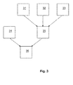
- Fig. 3 shows an example of how water content of a fuel for a combustion process may be determined according to the invention.
- Absolute water content ⁇ fwm of flue gases from a combustion process is measured in stage 31.
- the gauge metering the absolute water content ⁇ fwm is situated e.g. in the flue gas duct leading the flue gases out from a combustion chamber of a power station or similar.
- Absolute water content ⁇ am of combustion air is measured in stage 32 with a suitable instrument, situated e.g. in the combustion air duct leading to the combustion chamber.
- Absolute water content of the flue gases originating from the fuel and the combustion reaction i.e. the corrected water content ⁇ fwc is calculated in stage 35.
- Fig. 4 shows an example of a method for operating a combustion process according to the invention.
- Arrow 41 illustrates the fuel fed into the combustion process, i.e. into combustion chamber 55.
- Arrow 43 illustrates combustion air
- 45 is the energy produced by the combustion.
- Arrow 47 depicts the flue gases.
- Arrow 49 describes how part of the flue gases are recirculated into the combustion chamber as circulation gas.
- Arrow 51 describes the chemicals for reducing NOx from the combustion gases.
- Arrow 53 depicts the various means for affecting to the temperature in the combustion chamber. Boxes on the arrows describe means and devices, such as instruments, gauges, meters, indicators and valves for measuring and controlling the parameters of the arrows.
- Box 42 indicates e.g.
- Box 44 indicates instruments to measure and regulate e.g. amount of combustion air fed into the combustion chamber, and possibly amount and/or portions of one or more of primary, secondary and tertiary combustion air. Box 44 also includes instrument for metering absolute water content of the combustion air.
- Box 46 depicts instruments measuring the amount of energy produced in the combustion chamber 55.
- Box 48 depicts instruments measuring absolute water content and oxygen content of the flue gases.
- Box 50 indicates instruments to measure and regulate the amount of circulation gas.
- Box 52 indicates instruments to regulate the amount of chemicals fed to the combustion process to reduce NOx in the flue gases.
- Box 54 indicates instruments to measure and regulate the temperature in the combustion chamber.
- the method depicted in Fig. 4 functions in the following way. Fuel and combustion air are fed into the combustion chamber 55 at 41 and 43 respectively. Heat 45 and flue gases are produced. The flue gases are transported out of the combustion chamber 55 through a flue gas duct at 47. A plurality of measured variables are measured, including absolute water content of the flue gases at box 48, absolute water content of the combustion air at box 44, oxygen content of the flue gases at box 48.
- a plurality of operating parameters are regulated as a function of the measured variables.
- the operating parameters include amount of fuel fed into the combustion chamber at box 42, amount of combustion air fed into the combustion chamber at box 44, amount and/or portions of one or more of primary, secondary and tertiary combustion air at box 44, amount of circulation gas at box 50, amount of chemicals to reduce NOx in the flue gases at box 52 and combustion temperature at box 54.
- One of the measured variables in the method depicted in Fig. 4 is the water content of the fuel, which is determined according to the invention, e.g. in the way explained in Fig. 3 .
Landscapes
- Engineering & Computer Science (AREA)
- Chemical & Material Sciences (AREA)
- Health & Medical Sciences (AREA)
- Life Sciences & Earth Sciences (AREA)
- Biochemistry (AREA)
- Medicinal Chemistry (AREA)
- Physics & Mathematics (AREA)
- Analytical Chemistry (AREA)
- Food Science & Technology (AREA)
- General Health & Medical Sciences (AREA)
- General Physics & Mathematics (AREA)
- Immunology (AREA)
- Pathology (AREA)
- Combustion & Propulsion (AREA)
- Mechanical Engineering (AREA)
- General Engineering & Computer Science (AREA)
- Regulation And Control Of Combustion (AREA)
Abstract

Description
- The invention relates to operating combustion processes, e.g. in power plants. The invention especially relates to a new method of determining water content of a fuel for a combustion process.
- Many fuels, such as wood or peat, include moisture, i.e. water. The moisture content or water content of a fuel affects its heat value. Therefore, the price of the fuel for power plants, such as thermal power stations and combined heat and power stations is based on the heat value of the fuel. Water content of the fuel fed into a combustion process may vary significantly with time. In power plants and thermal power stations the water content of the fuel is usually determined by manually analyzing samples of the fuel. The sample is weighed, dried and weighed again, the difference between the two masses indicating the amount of water in the fuel.
- The manual methods are slow. There is no real possibility to notice variations in the water content with a reasonable accuracy. As a consequence, the price paid for the fuel is normally wrong. Also, the effect of the variable amount of water fed into the combustion chamber may not be adequately taken into account when operating the combustion process.
- Patent publication
US 6,752,093 B2 describes a refuse incineration plant, where moisture content of the flue gases is used as measure for the calorific value of the refuse. But it does not present a solution for determining water content of a fuel, let alone one that would take into account all the important factors in an adequate way. - It is an object of the present invention to reduce or even eliminate the above-mentioned problems appearing in prior art.
- The present invention has an object of providing a method of determining water content of a fuel for a combustion process, which method is not based on individual samples of the fuel but a continuous measuring of the process.
- An object of the present invention is to reduce the influence of variable water content, composition, grain size or temperature of the fuel on the determination of the water content of the fuel.
- An object of the present invention is to allow the determination of the water content of the fuel after the combustion of the fuel.
- An object of the present invention is to allow accurate determination of water content of an icy fuel.
- An object of the present invention is to allow accurate and swift regulating of operating parameters of a combustion process, especially in power plants, such as thermal power stations and combined heat and power stations.
- Among others, in order to realize the objects mentioned above, method of determining water content of a fuel and other objects according to the invention are characterized by what is presented in the enclosed independent claims.
- The embodiments, examples and advantages mentioned in this text relate, where applicable, to the methods, the apparatuses and the power plants according to the invention, even though it is not always specifically mentioned.
- The embodiments of the invention are suitable to be used in different kinds of energy producing facilities with combustion processes. The invention is suitable for many kinds of combustion chambers, e.g. for Fluidized Bed Combustion (FBC), grate fired boilers and rotary-kiln incinerators.
- The invention is especially suitable for combustion processes using only one fuel type or grade.
- The embodiments of the invention are especially suitable to be used with different kinds of biofuels such as wood and peat. Other fuels, such as coal, are also suitable. Especially suitable are fuels having a relatively homogenous chemical composition, e.g. wood, peat and coal.
- It has now been found that water content of a fuel can be determined with an indirect method in which the water content of the unburned fuel is not measured from the fuel itself. The idea is based on the fact that the water in the fuel will be present in flue gases, the water content of which is easily measured. Water in the flue gases originates from either:
- water in the combustion air,
- water in the fuel, or
- water from the combustion process, i.e. the chemical reaction.
- According to the invention the determination of the water content of a fuel is based on measuring water content of the combustion air and water content of the flue gases. Assuming that the fuel has a chemically homogenous composition this measured data may be converted into water content of the fuel with a small number of mathematical equations presented below.
- In a typical method of determining water content of a fuel for a combustion process according to the invention the water content y of a fuel is calculated from

where ωfwm is measured absolute water content of the flue gases, ωam is measured absolute water content of the combustion air, and d is a coefficient for absolute water content of combustion air. d may be obtained e.g. from a database. Coefficients a, b and c are specific for a specific fuel. They may be obtained from e.g. a database. - In an embodiment of the invention the determination of the water content of a fuel is also based on measuring oxygen content in the flue gases.
- In an embodiment of the invention the coefficients a, b and c are obtained from


where a1, a2, b1, b2, c1 and c2 are empirically determined coefficients for the specific fuel, obtained e.g. from a database. z is measured oxygen content of the flue gases in %-vol. - In an embodiment of the invention d is obtained from

where d1 and d2 are empirically determined coefficients for the specific fuel, obtained e.g. from a database. z is measured oxygen content of the flue gases in %-vol. - When the coefficients a1, a2, b1, b2, c1, c2, d1 and d2 are known, the water content of a fuel can be determined by solving simple mathematical equations. The computing power needed to solve such equations is very small. Thus e.g. a small logic circuit is enough for the computing.
- The invention is easily realized and requires only minor investments. The measurements needed may be done with instruments, gauges or sensors readily available in prior art. The water content of the combustion air and the flue gases may be measured e.g. with a normal humidity sensor for gases, sold e.g. by Vaisala. An oxygen content sensor for flue gases is already normally installed in power plants for determination of air fuel ratio of the combustion process. Simple wiring or some other data-communication means are needed between the sensors and the logic. The flue gases may need a cooler before being measured. Some new piping and control valves may be required.
- The coefficients a1, a2, b1, b2, c1, c2, d1 and d2 are specific for any fuel used. Usually one set of coefficients can be used for same fuel. Naturally, the fuel composition may vary significantly e.g. between different geographical sources of the fuel. Therefore, sometimes even different batches of the same fuel may require use of different coefficients. In practise, the user of the fuel, such as the power plant operator, may acquire these coefficients e.g. from a database. Also the supplier of the fuel may give the coefficients for the fuel purchased.
- In an embodiment of the invention the coefficients a1, a2, b1, b2, c1, c2, d1 and d2 are determined based on combustion calculations. Each fuel has its own chemical composition and therefore specific values for the coefficients. One embodiment of such determination process for the coefficients is depicted with the following steps 1-6. All the calculations needed are known prior art as such and not discussed in more detail in this text.
- Step 1: Water content of flue gas is calculated with several values for residual oxygen (02) content in flue gases and several fuel water contents. The result is a matrix of values of flue gas water content in kg/kgdg (kg water per kg dry gas). Relative humidity of the combustion air can be assumed as 0 %.
- Step 2: A group of quadratic curves is formed from the values of the matrix in Step 1. Each quadratic curve is representing fuel water content as function of absolute water content of the flue gases with certain residual oxygen (02) content; i.e a group of curves with different residual 02 content is formed.
- Step 3: A mathematical equation is formed for each individual curve in Step 2 so that group of quadratic equations is formed. The form of the equation is shown in equation [1] above.
- Step 4: In the equation [1] a, b and c are varying depending on the residual 02 content of the flue gas. From each quadratic curve in Step 3 values for a, b and c can be obtained. Values for a, b and c are forming linear equations as a function of residual oxygen (02) in flue gases. The form is shown in equations [2], [3] and [4] above.
- Step 5: Values a1, a2, b1, b2, c1 and c2 are obtained as constants in each linear equation obtained in
Step 4. - Step 6: Values d1 and d2 represent affection of combustion air humidity in equation [5]. Values are calculated as a function of residual oxygen (02) content in flue gases.
- Each fuel with a certain chemical composition has its own specific coefficients a1, a2, b1, b2, c1, c2, d1 and d2.
- The invention also relates to an apparatus for determining water content of a fuel for a combustion process, which apparatus comprises a computer or a logic circuit which is capable of calculating, according to the invention, the water content of the fuel when it is fed with certain measurement values from the process. A typical apparatus of this kind comprises at least:
- a first device for metering oxygen content of the flue gases,
- a second device for metering absolute water content of the flue gases,
- a third device for metering water content of the combustion air,
- a computer with a memory, a processor and a program code runnable on the processor for determining water content of the fuel according to the invention.
- The invention also relates to a power plant comprising an apparatus according to the invention for determining the water content of a fuel fed into a combustion chamber. A typical power plant of this kind comprises at least:
- a combustion chamber,
- feeding means for feeding fuel and combustion air into the combustion chamber in a controlled manner,
- a flue gas duct for transporting flue gases out of the combustion chamber,
- energy recovery system for recovering energy produced in the combustion chamber.
- The invention also relates to a method for operating a combustion process in which the water content of the fuel is determined according to the invention and used as one of the measured variables when regulating one or more operating parameters of the combustion process. One typical method of this kind comprises at least the following steps:
- feeding a fuel and combustion air into a combustion chamber,
- producing heat and flue gases in the combustion chamber,
- transporting the flue gases out of the combustion chamber through a flue gas duct,
- regulating a plurality of operating parameters, including at least one operating parameter from the group of
- amount of fuel fed into the combustion chamber
- amount of combustion air fed into the combustion chamber,
- amount and/or portions of one or more of primary, secondary and tertiary combustion air,
- amount of circulation gas,
- amount of chemicals to reduce NOx, i.e. nitrogen oxides in the flue gases,
- combustion temperature, especially to reduce NOx in the flue gases, as a function of a plurality of measured variables, including at least the following measured variables:
- absolute water content of the flue gases,
- absolute water content of the combustion air,
- oxygen content of the flue gases,
- water content of the fuel.
- A method for operating a combustion process of this type can be used e.g. in a power plant according to the invention.
- The invention is described in more detail below with reference to the enclosed schematic drawing, in which
- Figure 1
- shows quadratic equations and values for peat water content as a function of absolute water content of the flue gases at certain residual oxygen content in flue gases,
- Figure 2
- shows linear equations and values for coefficients a, b and c as a function of residual oxygen content in flue gases,
- Figure 3
- shows an example of a method according to the invention, and
- Figure 4
- shows an example of method for operating a combustion process according to the invention.
- In the following we describe a calculation process with 6 steps for defining coefficients a1, a2, b1, b2, c1, c2, d1 and d2 to be used in calculations according to the invention for a certain type of Finnish peat.
- Step 1: Moisture i.e. water content of flue gas is calculated with several values (2 to 5 %-vol.) for residual oxygen (02) content in flue gases and several different values (34 to 52 %) for fuel water content. The result is a matrix (Table 1) of values of flue gas water content in kg/kgdg (kg water per kg dry gas). Relative humidity of the combustion air can be assumed as 0 %.
- Step 2: A group of quadratic curves is formed from the values of the matrix i.e. Table 1. Each quadratic curve is representing fuel water content as function of absolute water content of the flue gas with certain residual 02 content; i.e a group of curves with different residual 02 content is formed. In
Fig. 1 are shown three curves, i.e. for residual 02 content of 3 %, 4 % and 5 %.Table 1: Fuel moisture content % Water content in flue gas [kg/kg] for typical Finnish peat 5,00 %- vol 4,00 %-vol 3,000 %-vol 2,000 %- vol 34 0,1074 0,1136 0,1199 0,1262 36 0,1124 0,1190 0,1255 0,1321 38 0,1178 0,1247 0,1316 0,1384 40 0,1235 0,1307 0,1380 0,1451 42 0,1297 0,1372 0,1448 0,1523 44 0,1362 0,1442 0,1521 0,1601 46 0,1433 0,1516 0,1600 0,1683 48 0,1509 0,1597 0,1685 0,1773 50 0,1591 0,1684 0,1777 0,1869 52 0,1680 0,1778 0,1876 0,1974 - Step 3: A mathematical equation is formed for each individual curve from step 2 so that group of quadratic equations is formed. The form of the equation is shown in equation [1] above. The three equations for the three curves in
Fig. 1 are shown inFig. 1 . - Step 4: In the equation [1] a, b and c are varying depending on the residual 02 content of the flue gas. From each quadratic curve values for a, b and c can be obtained. Values for a, b and c are forming linear equations as a function of residual oxygen (02) in flue gases. The form of these equations is shown in equations [2], [3] and [4] above. The equations for a, b and c are shown in
Fig. 2 . - Step 5: Values a1, a2, b1, b2, c1 and c2 are obtained as constants in each equation mentioned in
Step 4 and shown inFig. 2 . - Step 6: Values d1 and d2 represent affection of combustion air humidity in equation [5]. Values are calculated as a function of residual oxygen (02) content in flue gases.
- In the embodiment described above the coefficients have following values:
- a1 is -156.85
- a2 is -769.87
- b1 is 38.595
- b2 is 530.3
- c1 is -0.057
- c2 is -25.417
- d1 is 0.0028
- d2 is 0.9369.
- When these coefficients are fed into equations [1] to [5] the water content of the peat used as a fuel can be calculated continuously in the power plant. Coefficients for a number of different fuels may be stored e.g. in a database or similar, from where the computer program calculating the water content y of the fuel obtains them when needed. One possibility is to input the coefficients manually to the computer program, if the chemical composition of the fuel changes.
-
Fig. 3 shows an example of how water content of a fuel for a combustion process may be determined according to the invention. Absolute water content ωfwm of flue gases from a combustion process is measured instage 31. The gauge metering the absolute water content ωfwm is situated e.g. in the flue gas duct leading the flue gases out from a combustion chamber of a power station or similar. Absolute water content ωam of combustion air is measured instage 32 with a suitable instrument, situated e.g. in the combustion air duct leading to the combustion chamber. Absolute water content of the flue gases originating from the fuel and the combustion reaction, i.e. the corrected water content ωfwc is calculated instage 35. It is obtained from equation ωfwc = ωfwm - d·ωam, where d is coefficient for absolute water content of the combustion air. Coefficient d is specific for the fuel used and obtained e.g. from a database instage 33. The water content y of the fuel is calculated instage 36 from y= a·ωfwc 2 + b·ωfwc + c or as it is written in equation [1]: y= a·(ωfwm - d·ωam)2 + b·(ωfwm - d·ωam) + c. Coefficients a, b and c are specific for the fuel used and obtained e.g. from a database instage 34. -
Fig. 4 shows an example of a method for operating a combustion process according to the invention.Arrow 41 illustrates the fuel fed into the combustion process, i.e. intocombustion chamber 55.Arrow 43 illustrates combustion air, 45 is the energy produced by the combustion.Arrow 47 depicts the flue gases.Arrow 49 describes how part of the flue gases are recirculated into the combustion chamber as circulation gas.Arrow 51 describes the chemicals for reducing NOx from the combustion gases.Arrow 53 depicts the various means for affecting to the temperature in the combustion chamber. Boxes on the arrows describe means and devices, such as instruments, gauges, meters, indicators and valves for measuring and controlling the parameters of the arrows.Box 42 indicates e.g. the regulator for the fuel flow into the combustion process and the instrument metering the amount of fuel fed into the combustion chamber.Box 44 indicates instruments to measure and regulate e.g. amount of combustion air fed into the combustion chamber, and possibly amount and/or portions of one or more of primary, secondary and tertiary combustion air.Box 44 also includes instrument for metering absolute water content of the combustion air.Box 46 depicts instruments measuring the amount of energy produced in thecombustion chamber 55.Box 48 depicts instruments measuring absolute water content and oxygen content of the flue gases.Box 50 indicates instruments to measure and regulate the amount of circulation gas.Box 52 indicates instruments to regulate the amount of chemicals fed to the combustion process to reduce NOx in the flue gases.Box 54 indicates instruments to measure and regulate the temperature in the combustion chamber. - The method depicted in
Fig. 4 functions in the following way. Fuel and combustion air are fed into thecombustion chamber 55 at 41 and 43 respectively.Heat 45 and flue gases are produced. The flue gases are transported out of thecombustion chamber 55 through a flue gas duct at 47. A plurality of measured variables are measured, including absolute water content of the flue gases atbox 48, absolute water content of the combustion air atbox 44, oxygen content of the flue gases atbox 48. - A plurality of operating parameters are regulated as a function of the measured variables. The operating parameters include amount of fuel fed into the combustion chamber at
box 42, amount of combustion air fed into the combustion chamber atbox 44, amount and/or portions of one or more of primary, secondary and tertiary combustion air atbox 44, amount of circulation gas atbox 50, amount of chemicals to reduce NOx in the flue gases atbox 52 and combustion temperature atbox 54. - One of the measured variables in the method depicted in
Fig. 4 is the water content of the fuel, which is determined according to the invention, e.g. in the way explained inFig. 3 . - The figures show only a few preferred embodiments according to the invention. Facts of secondary importance with regards to the main idea of the invention, facts known as such or evident for a person skilled in the art are not necessarily separately shown in the figures. It is apparent to a person skilled in the art that the invention is not limited exclusively to the examples described above, but that the invention can vary within the scope of the claims presented below. The dependent claims present some possible embodiments of the invention, and they are not to be considered to restrict the scope of protection of the invention as such.
Claims (11)
- A method of determining water content of a fuel for a combustion process, the method comprising at least the following steps:- measuring absolute water content ωfwm of flue gases from the combustion process,- measuring absolute water content ωam of combustion air,characterized in calculating the water content y of the fuel from

where a, b and c are coefficients for the fuel, and d is coefficient for absolute water content of the combustion air. - Method according to claim 1, characterized in- measuring oxygen content z of the flue gases from the combustion process in %-vol.
- Method according to claim 2, characterized in that d is obtained from

where d1 and d2 are empirically determined coefficients for the fuel. - Method according to claim 2 or 3, characterized in that a is obtained from

where a1 and a2 are empirically determined coefficients for the fuel. - Method according to any of claima 2 to 4, characterized in that b is obtained from

where b1 and b2 are empirically determined coefficients for the fuel. - Method according to any of claims 2 to 5, characterized in that c is obtained from

where c1 and c2 are empirically determined coefficients for the fuel. - Method according to claim 1, characterized in that the coefficients a, b and c are determined based on combustion calculations with at least the following steps:- creating a matrix of values of flue gas water content as a function of several values for oxygen content z in flue gases and several fuel water contents y;- forming a group of quadratic curves from the values of the matrix, where each quadratic curve is representing fuel water content y as a function of absolute corrected water content ωfwc of the flue gases with certain oxygen content z in the flue gases, where ωfwc = ωfwm - d·ωam, i.e. a group of quadratic curves each with a different oxygen content is formed;- forming a mathematical equation in form y= a·(ωfwc)2 + b·(ωfwc) + c for each said quadratic curve;- obtaining values for a, b and c for each said quadratic curve.
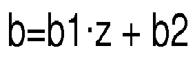
- Method according to claim 7, characterized in that further, coefficients a, b and c are determined from said values for a, b and c for each said quadratic curve by:- forming linear equations for a, b and c as a function of the oxygen content z in flue gases, i.e.

 - obtaining coefficients a1, a2, b1, b2, c1 and c2 from these linear equations.
 - Method for operating a combustion process, the method comprising at least- feeding a fuel and combustion air into a combustion chamber,- producing heat and flue gases in the combustion chamber,- transporting the flue gases out of the combustion chamber through a flue gas duct,- regulating a plurality of operating parameters, including at least one operating parameter from the group of- amount of fuel fed into the combustion chamber,- amount of combustion air fed into the combustion chamber,- amount and/or portions of one or more of primary, secondary and tertiary combustion air,- amount of circulation gas,- amount of chemicals to reduce NOx in the flue gases,- combustion temperature, especially to reduce NOx in the flue gases, as a function of a plurality of measured variables, including at least one measured variable from the group ofcharacterized in that water content of the fuel is determined according to any of the methods of claims 1 to 8.- absolute water content of the flue gases,- absolute water content of the combustion air,- oxygen content of the flue gases,- water content of the fuel,
- Apparatus for determining water content of a fuel for a combustion process, which apparatus comprises:- a first device for metering oxygen content z of the flue gases,- a second device for metering absolute water content ωfwm of flue gases,- a third device for metering water content ωam of the combustion air, characterized in that the apparatus further comprises- a computer with a memory, a processor and a program code runnable on the processor for determining water content of the fuel according to any of the methods of claims 1 to 8.
- A power plant comprising at least- a combustion chamber,- feeding means for feeding fuel and combustion air into the combustion chamber in a controlled manner,- a flue gas duct for transporting flue gases out of the combustion chamber,- energy recovery system for recovering energy produced in the combustion chamber,
characterized in that the power plant further comprises an apparatus according to claim 10 for determining water content of the fuel fed into the combustion chamber.
Priority Applications (1)
| Application Number | Priority Date | Filing Date | Title |
|---|---|---|---|
| EP12189579.1A EP2725354B1 (en) | 2012-10-23 | 2012-10-23 | Post-combustion determination of the water content of a solid fuel |
Applications Claiming Priority (1)
| Application Number | Priority Date | Filing Date | Title |
|---|---|---|---|
| EP12189579.1A EP2725354B1 (en) | 2012-10-23 | 2012-10-23 | Post-combustion determination of the water content of a solid fuel |
Publications (2)
| Publication Number | Publication Date |
|---|---|
| EP2725354A1 true EP2725354A1 (en) | 2014-04-30 |
| EP2725354B1 EP2725354B1 (en) | 2018-05-09 |
Family
ID=47325825
Family Applications (1)
| Application Number | Title | Priority Date | Filing Date |
|---|---|---|---|
| EP12189579.1A Active EP2725354B1 (en) | 2012-10-23 | 2012-10-23 | Post-combustion determination of the water content of a solid fuel |
Country Status (1)
| Country | Link |
|---|---|
| EP (1) | EP2725354B1 (en) |
Cited By (1)
| Publication number | Priority date | Publication date | Assignee | Title |
|---|---|---|---|---|
| CN106990105A (en) * | 2017-05-11 | 2017-07-28 | 中国民用航空总局第二研究所 | Test paper of Aviation Fuel micro-water content and preparation method thereof |
Citations (2)
| Publication number | Priority date | Publication date | Assignee | Title |
|---|---|---|---|---|
| US6752093B2 (en) | 2000-12-08 | 2004-06-22 | Von Roll Umwelttechnik Ag | Method for operating a refuse incineration plant |
| EP1832809A1 (en) * | 2006-03-09 | 2007-09-12 | ABB Technology AG | Controlling a waste combustion process |
-
2012
- 2012-10-23 EP EP12189579.1A patent/EP2725354B1/en active Active
Patent Citations (2)
| Publication number | Priority date | Publication date | Assignee | Title |
|---|---|---|---|---|
| US6752093B2 (en) | 2000-12-08 | 2004-06-22 | Von Roll Umwelttechnik Ag | Method for operating a refuse incineration plant |
| EP1832809A1 (en) * | 2006-03-09 | 2007-09-12 | ABB Technology AG | Controlling a waste combustion process |
Non-Patent Citations (1)
| Title |
|---|
| SVEN HERMANSSON ET AL: "On-line monitoring of fuel moisture-content in biomass-fired furnaces by measuring relative humidity of the flue gases", CHEMICAL ENGINEERING RESEARCH AND DESIGN, PART A, INSTITUTION OF CHEMICAL ENGINEERS, XX, vol. 89, no. 11, 29 March 2011 (2011-03-29), pages 2470 - 2476, XP028307244, ISSN: 0263-8762, [retrieved on 20110416], DOI: 10.1016/J.CHERD.2011.03.018 * |
Cited By (1)
| Publication number | Priority date | Publication date | Assignee | Title |
|---|---|---|---|---|
| CN106990105A (en) * | 2017-05-11 | 2017-07-28 | 中国民用航空总局第二研究所 | Test paper of Aviation Fuel micro-water content and preparation method thereof |
Also Published As
| Publication number | Publication date |
|---|---|
| EP2725354B1 (en) | 2018-05-09 |
Similar Documents
| Publication | Publication Date | Title |
|---|---|---|
| Iliyas et al. | RBF neural network inferential sensor for process emission monitoring | |
| Peisheng et al. | Prediction of grindability with multivariable regression and neural network in Chinese coal | |
| EP3265791B1 (en) | Determination of fluid parameters | |
| KR100416114B1 (en) | Method and apparatus for the incineration of waste materials | |
| Rashidian et al. | Effect of freeboard deflectors in the fixed bed combustion of biomass | |
| US7862227B2 (en) | Method and apparatus for testing building materials | |
| CN1315659A (en) | Method for predetecting combustible limiting value of complicated mixture | |
| CN104807500B (en) | The warehouse separated type air preheater method for testing performance of large-sized station boiler three | |
| Kortela et al. | Fuel moisture soft-sensor and its validation for the industrial BioPower 5 CHP plant | |
| Stanisławski et al. | Reduction of the CO emission from wood pellet small-scale boiler using model-based control | |
| de Freitas et al. | Optimization method for pneumatic conveying parameters and energy consumption performance analysis of a compact blow tank | |
| US20140047899A1 (en) | Device for determining a composition of fuel in a combustion chamber of a power station | |
| EP2725354A1 (en) | Post-combustion determination of the water content of a solid fuel | |
| Cremona et al. | Application of the Kragten method in order to evaluate the uncertainty of the heat release rate determination using of the cone calorimeter | |
| CN115575337A (en) | High precision atmospheric CO 2 Concentration observation data calibration method, system and equipment | |
| Majanne et al. | EU emission trading related CO2 monitoring in power plants | |
| Salo et al. | Emission measurements with gravimetric impactors and electrical devices: An aerosol instrument comparison | |
| CN116879513B (en) | Verification method, device, equipment and storage medium of gas analysis system | |
| Saramud et al. | A new approach to multi-version decision-making to improve the reliability of environmental monitoring parameters | |
| US20190257808A1 (en) | Chemo-Metrical Prediction of Methane Index for the Natural Gas | |
| Ren et al. | Concentration-independent unburnt carbon content metering in fly ash using a waveguide | |
| US20110287372A1 (en) | Method and Device for Monitoring the Combustion Process in a Power Station on the Basis of an Actual Concentration Distribution of a Material | |
| JPS5616024A (en) | Inspecting method of combustion of combusting apparatus | |
| Ropp et al. | XyloChips–Continuous measurement of woodchips energy content | |
| Brundish et al. | Measurement of smoke particle size and distribution within a gas turbine combustor |
Legal Events
| Date | Code | Title | Description |
|---|---|---|---|
| PUAI | Public reference made under article 153(3) epc to a published international application that has entered the european phase |
Free format text: ORIGINAL CODE: 0009012 |
|
| 17P | Request for examination filed |
Effective date: 20121023 |
|
| AK | Designated contracting states |
Kind code of ref document: A1 Designated state(s): AL AT BE BG CH CY CZ DE DK EE ES FI FR GB GR HR HU IE IS IT LI LT LU LV MC MK MT NL NO PL PT RO RS SE SI SK SM TR |
|
| AX | Request for extension of the european patent |
Extension state: BA ME |
|
| 17P | Request for examination filed |
Effective date: 20141030 |
|
| RBV | Designated contracting states (corrected) |
Designated state(s): AL AT BE BG CH CY CZ DE DK EE ES FI FR GB GR HR HU IE IS IT LI LT LU LV MC MK MT NL NO PL PT RO RS SE SI SK SM TR |
|
| 17Q | First examination report despatched |
Effective date: 20171204 |
|
| GRAP | Despatch of communication of intention to grant a patent |
Free format text: ORIGINAL CODE: EPIDOSNIGR1 |
|
| INTG | Intention to grant announced |
Effective date: 20180209 |
|
| GRAS | Grant fee paid |
Free format text: ORIGINAL CODE: EPIDOSNIGR3 |
|
| GRAA | (expected) grant |
Free format text: ORIGINAL CODE: 0009210 |
|
| AK | Designated contracting states |
Kind code of ref document: B1 Designated state(s): AL AT BE BG CH CY CZ DE DK EE ES FI FR GB GR HR HU IE IS IT LI LT LU LV MC MK MT NL NO PL PT RO RS SE SI SK SM TR |
|
| REG | Reference to a national code |
Ref country code: GB Ref legal event code: FG4D |
|
| REG | Reference to a national code |
Ref country code: CH Ref legal event code: EP Ref country code: AT Ref legal event code: REF Ref document number: 998042 Country of ref document: AT Kind code of ref document: T Effective date: 20180515 |
|
| REG | Reference to a national code |
Ref country code: IE Ref legal event code: FG4D |
|
| REG | Reference to a national code |
Ref country code: DE Ref legal event code: R096 Ref document number: 602012046115 Country of ref document: DE |
|
| REG | Reference to a national code |
Ref country code: SE Ref legal event code: TRGR |
|
| REG | Reference to a national code |
Ref country code: NL Ref legal event code: MP Effective date: 20180509 |
|
| REG | Reference to a national code |
Ref country code: LT Ref legal event code: MG4D |
|
| REG | Reference to a national code |
Ref country code: FR Ref legal event code: PLFP Year of fee payment: 7 |
|
| PG25 | Lapsed in a contracting state [announced via postgrant information from national office to epo] |
Ref country code: ES Free format text: LAPSE BECAUSE OF FAILURE TO SUBMIT A TRANSLATION OF THE DESCRIPTION OR TO PAY THE FEE WITHIN THE PRESCRIBED TIME-LIMIT Effective date: 20180509 Ref country code: LT Free format text: LAPSE BECAUSE OF FAILURE TO SUBMIT A TRANSLATION OF THE DESCRIPTION OR TO PAY THE FEE WITHIN THE PRESCRIBED TIME-LIMIT Effective date: 20180509 Ref country code: BG Free format text: LAPSE BECAUSE OF FAILURE TO SUBMIT A TRANSLATION OF THE DESCRIPTION OR TO PAY THE FEE WITHIN THE PRESCRIBED TIME-LIMIT Effective date: 20180809 Ref country code: NO Free format text: LAPSE BECAUSE OF FAILURE TO SUBMIT A TRANSLATION OF THE DESCRIPTION OR TO PAY THE FEE WITHIN THE PRESCRIBED TIME-LIMIT Effective date: 20180809 |
|
| PG25 | Lapsed in a contracting state [announced via postgrant information from national office to epo] |
Ref country code: LV Free format text: LAPSE BECAUSE OF FAILURE TO SUBMIT A TRANSLATION OF THE DESCRIPTION OR TO PAY THE FEE WITHIN THE PRESCRIBED TIME-LIMIT Effective date: 20180509 Ref country code: HR Free format text: LAPSE BECAUSE OF FAILURE TO SUBMIT A TRANSLATION OF THE DESCRIPTION OR TO PAY THE FEE WITHIN THE PRESCRIBED TIME-LIMIT Effective date: 20180509 Ref country code: RS Free format text: LAPSE BECAUSE OF FAILURE TO SUBMIT A TRANSLATION OF THE DESCRIPTION OR TO PAY THE FEE WITHIN THE PRESCRIBED TIME-LIMIT Effective date: 20180509 Ref country code: GR Free format text: LAPSE BECAUSE OF FAILURE TO SUBMIT A TRANSLATION OF THE DESCRIPTION OR TO PAY THE FEE WITHIN THE PRESCRIBED TIME-LIMIT Effective date: 20180810 Ref country code: NL Free format text: LAPSE BECAUSE OF FAILURE TO SUBMIT A TRANSLATION OF THE DESCRIPTION OR TO PAY THE FEE WITHIN THE PRESCRIBED TIME-LIMIT Effective date: 20180509 |
|
| REG | Reference to a national code |
Ref country code: AT Ref legal event code: MK05 Ref document number: 998042 Country of ref document: AT Kind code of ref document: T Effective date: 20180509 |
|
| PG25 | Lapsed in a contracting state [announced via postgrant information from national office to epo] |
Ref country code: CZ Free format text: LAPSE BECAUSE OF FAILURE TO SUBMIT A TRANSLATION OF THE DESCRIPTION OR TO PAY THE FEE WITHIN THE PRESCRIBED TIME-LIMIT Effective date: 20180509 Ref country code: SK Free format text: LAPSE BECAUSE OF FAILURE TO SUBMIT A TRANSLATION OF THE DESCRIPTION OR TO PAY THE FEE WITHIN THE PRESCRIBED TIME-LIMIT Effective date: 20180509 Ref country code: PL Free format text: LAPSE BECAUSE OF FAILURE TO SUBMIT A TRANSLATION OF THE DESCRIPTION OR TO PAY THE FEE WITHIN THE PRESCRIBED TIME-LIMIT Effective date: 20180509 Ref country code: RO Free format text: LAPSE BECAUSE OF FAILURE TO SUBMIT A TRANSLATION OF THE DESCRIPTION OR TO PAY THE FEE WITHIN THE PRESCRIBED TIME-LIMIT Effective date: 20180509 Ref country code: DK Free format text: LAPSE BECAUSE OF FAILURE TO SUBMIT A TRANSLATION OF THE DESCRIPTION OR TO PAY THE FEE WITHIN THE PRESCRIBED TIME-LIMIT Effective date: 20180509 Ref country code: AT Free format text: LAPSE BECAUSE OF FAILURE TO SUBMIT A TRANSLATION OF THE DESCRIPTION OR TO PAY THE FEE WITHIN THE PRESCRIBED TIME-LIMIT Effective date: 20180509 Ref country code: EE Free format text: LAPSE BECAUSE OF FAILURE TO SUBMIT A TRANSLATION OF THE DESCRIPTION OR TO PAY THE FEE WITHIN THE PRESCRIBED TIME-LIMIT Effective date: 20180509 |
|
| REG | Reference to a national code |
Ref country code: DE Ref legal event code: R097 Ref document number: 602012046115 Country of ref document: DE |
|
| PG25 | Lapsed in a contracting state [announced via postgrant information from national office to epo] |
Ref country code: SM Free format text: LAPSE BECAUSE OF FAILURE TO SUBMIT A TRANSLATION OF THE DESCRIPTION OR TO PAY THE FEE WITHIN THE PRESCRIBED TIME-LIMIT Effective date: 20180509 Ref country code: IT Free format text: LAPSE BECAUSE OF FAILURE TO SUBMIT A TRANSLATION OF THE DESCRIPTION OR TO PAY THE FEE WITHIN THE PRESCRIBED TIME-LIMIT Effective date: 20180509 |
|
| PLBE | No opposition filed within time limit |
Free format text: ORIGINAL CODE: 0009261 |
|
| STAA | Information on the status of an ep patent application or granted ep patent |
Free format text: STATUS: NO OPPOSITION FILED WITHIN TIME LIMIT |
|
| 26N | No opposition filed |
Effective date: 20190212 |
|
| REG | Reference to a national code |
Ref country code: DE Ref legal event code: R119 Ref document number: 602012046115 Country of ref document: DE |
|
| PG25 | Lapsed in a contracting state [announced via postgrant information from national office to epo] |
Ref country code: SI Free format text: LAPSE BECAUSE OF FAILURE TO SUBMIT A TRANSLATION OF THE DESCRIPTION OR TO PAY THE FEE WITHIN THE PRESCRIBED TIME-LIMIT Effective date: 20180509 |
|
| REG | Reference to a national code |
Ref country code: CH Ref legal event code: PL |
|
| GBPC | Gb: european patent ceased through non-payment of renewal fee |
Effective date: 20181023 |
|
| REG | Reference to a national code |
Ref country code: BE Ref legal event code: MM Effective date: 20181031 |
|
| PG25 | Lapsed in a contracting state [announced via postgrant information from national office to epo] |
Ref country code: LU Free format text: LAPSE BECAUSE OF NON-PAYMENT OF DUE FEES Effective date: 20181023 Ref country code: MC Free format text: LAPSE BECAUSE OF FAILURE TO SUBMIT A TRANSLATION OF THE DESCRIPTION OR TO PAY THE FEE WITHIN THE PRESCRIBED TIME-LIMIT Effective date: 20180509 |
|
| REG | Reference to a national code |
Ref country code: IE Ref legal event code: MM4A |
|
| PG25 | Lapsed in a contracting state [announced via postgrant information from national office to epo] |
Ref country code: DE Free format text: LAPSE BECAUSE OF NON-PAYMENT OF DUE FEES Effective date: 20190501 |
|
| PG25 | Lapsed in a contracting state [announced via postgrant information from national office to epo] |
Ref country code: LI Free format text: LAPSE BECAUSE OF NON-PAYMENT OF DUE FEES Effective date: 20181031 Ref country code: BE Free format text: LAPSE BECAUSE OF NON-PAYMENT OF DUE FEES Effective date: 20181031 Ref country code: CH Free format text: LAPSE BECAUSE OF NON-PAYMENT OF DUE FEES Effective date: 20181031 |
|
| PG25 | Lapsed in a contracting state [announced via postgrant information from national office to epo] |
Ref country code: GB Free format text: LAPSE BECAUSE OF NON-PAYMENT OF DUE FEES Effective date: 20181023 Ref country code: IE Free format text: LAPSE BECAUSE OF NON-PAYMENT OF DUE FEES Effective date: 20181023 |
|
| PG25 | Lapsed in a contracting state [announced via postgrant information from national office to epo] |
Ref country code: AL Free format text: LAPSE BECAUSE OF FAILURE TO SUBMIT A TRANSLATION OF THE DESCRIPTION OR TO PAY THE FEE WITHIN THE PRESCRIBED TIME-LIMIT Effective date: 20180509 |
|
| PG25 | Lapsed in a contracting state [announced via postgrant information from national office to epo] |
Ref country code: MT Free format text: LAPSE BECAUSE OF NON-PAYMENT OF DUE FEES Effective date: 20181023 |
|
| PG25 | Lapsed in a contracting state [announced via postgrant information from national office to epo] |
Ref country code: TR Free format text: LAPSE BECAUSE OF FAILURE TO SUBMIT A TRANSLATION OF THE DESCRIPTION OR TO PAY THE FEE WITHIN THE PRESCRIBED TIME-LIMIT Effective date: 20180509 |
|
| PG25 | Lapsed in a contracting state [announced via postgrant information from national office to epo] |
Ref country code: PT Free format text: LAPSE BECAUSE OF FAILURE TO SUBMIT A TRANSLATION OF THE DESCRIPTION OR TO PAY THE FEE WITHIN THE PRESCRIBED TIME-LIMIT Effective date: 20180509 |
|
| PG25 | Lapsed in a contracting state [announced via postgrant information from national office to epo] |
Ref country code: MK Free format text: LAPSE BECAUSE OF NON-PAYMENT OF DUE FEES Effective date: 20180509 Ref country code: HU Free format text: LAPSE BECAUSE OF FAILURE TO SUBMIT A TRANSLATION OF THE DESCRIPTION OR TO PAY THE FEE WITHIN THE PRESCRIBED TIME-LIMIT; INVALID AB INITIO Effective date: 20121023 Ref country code: CY Free format text: LAPSE BECAUSE OF FAILURE TO SUBMIT A TRANSLATION OF THE DESCRIPTION OR TO PAY THE FEE WITHIN THE PRESCRIBED TIME-LIMIT Effective date: 20180509 |
|
| PG25 | Lapsed in a contracting state [announced via postgrant information from national office to epo] |
Ref country code: IS Free format text: LAPSE BECAUSE OF FAILURE TO SUBMIT A TRANSLATION OF THE DESCRIPTION OR TO PAY THE FEE WITHIN THE PRESCRIBED TIME-LIMIT Effective date: 20180909 |
|
| PGFP | Annual fee paid to national office [announced via postgrant information from national office to epo] |
Ref country code: FI Payment date: 20241017 Year of fee payment: 13 |
|
| PGFP | Annual fee paid to national office [announced via postgrant information from national office to epo] |
Ref country code: FR Payment date: 20241017 Year of fee payment: 13 |
|
| PGFP | Annual fee paid to national office [announced via postgrant information from national office to epo] |
Ref country code: SE Payment date: 20241018 Year of fee payment: 13 |