EP2725185A2 - Outil de fraisage d'ébavurage pour nettoyage de puits de forage - Google Patents
Outil de fraisage d'ébavurage pour nettoyage de puits de forage Download PDFInfo
- Publication number
- EP2725185A2 EP2725185A2 EP13189644.1A EP13189644A EP2725185A2 EP 2725185 A2 EP2725185 A2 EP 2725185A2 EP 13189644 A EP13189644 A EP 13189644A EP 2725185 A2 EP2725185 A2 EP 2725185A2
- Authority
- EP
- European Patent Office
- Prior art keywords
- tool
- piston
- mandrel
- blades
- cutting member
- Prior art date
- Legal status (The legal status is an assumption and is not a legal conclusion. Google has not performed a legal analysis and makes no representation as to the accuracy of the status listed.)
- Withdrawn
Links
- 238000004140 cleaning Methods 0.000 title abstract description 4
- 239000012530 fluid Substances 0.000 claims description 54
- 238000000034 method Methods 0.000 claims description 16
- 238000004891 communication Methods 0.000 claims description 8
- 238000003801 milling Methods 0.000 description 9
- 230000000712 assembly Effects 0.000 description 4
- 238000000429 assembly Methods 0.000 description 4
- 230000002028 premature Effects 0.000 description 4
- 230000005540 biological transmission Effects 0.000 description 3
- 238000012856 packing Methods 0.000 description 2
- 239000004215 Carbon black (E152) Substances 0.000 description 1
- 230000008878 coupling Effects 0.000 description 1
- 238000010168 coupling process Methods 0.000 description 1
- 238000005859 coupling reaction Methods 0.000 description 1
- 230000005484 gravity Effects 0.000 description 1
- 229930195733 hydrocarbon Natural products 0.000 description 1
- 150000002430 hydrocarbons Chemical class 0.000 description 1
- 238000003780 insertion Methods 0.000 description 1
- 230000037431 insertion Effects 0.000 description 1
- 238000009434 installation Methods 0.000 description 1
- 239000000463 material Substances 0.000 description 1
- 238000011084 recovery Methods 0.000 description 1
- 238000007789 sealing Methods 0.000 description 1
- 230000000087 stabilizing effect Effects 0.000 description 1
Images


Classifications
-
- E—FIXED CONSTRUCTIONS
- E21—EARTH OR ROCK DRILLING; MINING
- E21B—EARTH OR ROCK DRILLING; OBTAINING OIL, GAS, WATER, SOLUBLE OR MELTABLE MATERIALS OR A SLURRY OF MINERALS FROM WELLS
- E21B37/00—Methods or apparatus for cleaning boreholes or wells
-
- E—FIXED CONSTRUCTIONS
- E21—EARTH OR ROCK DRILLING; MINING
- E21B—EARTH OR ROCK DRILLING; OBTAINING OIL, GAS, WATER, SOLUBLE OR MELTABLE MATERIALS OR A SLURRY OF MINERALS FROM WELLS
- E21B10/00—Drill bits
- E21B10/26—Drill bits with leading portion, i.e. drill bits with a pilot cutter; Drill bits for enlarging the borehole, e.g. reamers
- E21B10/32—Drill bits with leading portion, i.e. drill bits with a pilot cutter; Drill bits for enlarging the borehole, e.g. reamers with expansible cutting tools
- E21B10/322—Drill bits with leading portion, i.e. drill bits with a pilot cutter; Drill bits for enlarging the borehole, e.g. reamers with expansible cutting tools cutter shifted by fluid pressure
-
- E—FIXED CONSTRUCTIONS
- E21—EARTH OR ROCK DRILLING; MINING
- E21B—EARTH OR ROCK DRILLING; OBTAINING OIL, GAS, WATER, SOLUBLE OR MELTABLE MATERIALS OR A SLURRY OF MINERALS FROM WELLS
- E21B10/00—Drill bits
- E21B10/26—Drill bits with leading portion, i.e. drill bits with a pilot cutter; Drill bits for enlarging the borehole, e.g. reamers
- E21B10/32—Drill bits with leading portion, i.e. drill bits with a pilot cutter; Drill bits for enlarging the borehole, e.g. reamers with expansible cutting tools
- E21B10/325—Drill bits with leading portion, i.e. drill bits with a pilot cutter; Drill bits for enlarging the borehole, e.g. reamers with expansible cutting tools the cutter being shifted by a spring mechanism
-
- E—FIXED CONSTRUCTIONS
- E21—EARTH OR ROCK DRILLING; MINING
- E21B—EARTH OR ROCK DRILLING; OBTAINING OIL, GAS, WATER, SOLUBLE OR MELTABLE MATERIALS OR A SLURRY OF MINERALS FROM WELLS
- E21B29/00—Cutting or destroying pipes, packers, plugs or wire lines, located in boreholes or wells, e.g. cutting of damaged pipes, of windows; Deforming of pipes in boreholes or wells; Reconditioning of well casings while in the ground
- E21B29/002—Cutting, e.g. milling, a pipe with a cutter rotating along the circumference of the pipe
- E21B29/005—Cutting, e.g. milling, a pipe with a cutter rotating along the circumference of the pipe with a radially-expansible cutter rotating inside the pipe, e.g. for cutting an annular window
-
- E—FIXED CONSTRUCTIONS
- E21—EARTH OR ROCK DRILLING; MINING
- E21B—EARTH OR ROCK DRILLING; OBTAINING OIL, GAS, WATER, SOLUBLE OR MELTABLE MATERIALS OR A SLURRY OF MINERALS FROM WELLS
- E21B37/00—Methods or apparatus for cleaning boreholes or wells
- E21B37/02—Scrapers specially adapted therefor
Definitions
- Embodiments of the invention generally relate to a wellbore cleaning tool.
- a wellbore tool that comprises a top sub; a cutting assembly that comprises a mandrel in fluid communication with the top sub; a piston disposed external to the mandrel; and a cutting member selectively movable into at least one of a retracted position, an extended position, and a deactivated position using the piston; and a bottom sub operable to close fluid flow through the tool.
- a method of operating a wellbore tool that comprises lowering the tool into a tubular using a work string; rotating a cutting assembly of the tool to remove irregularities from an inner surface of the tubular, wherein the cutting assembly includes a mandrel, a piston, and a cutting member; and actuating the cutting member into at least one of a retracted position, an extended position, and a deactivated position using the piston, wherein the piston is disposed external to the mandrel.
- Embodiments of the invention comprise a wellbore tool for cleaning the inner surfaces of wellbore tubulars.
- the wellbore tool may include a (360 degree circumferential) cutting mill operable to mill out and remove burrs from protruding inside a casing that are formed during a perforation job.
- the wellbore tool may be operable to create a smooth, clean casing inner diameter for running completion tools.
- a milling tool to remove burrs embodiments of the invention are applicable to removing debris, burrs, jagged edges, and/or other irregularities formed along the inner surface of any wellbore tubulars.
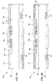
- Figure 1 illustrates a sectional view of a wellbore tool 10.
- the wellbore tool 10 may include a top sub 110, a cutting assembly 100, an intermediate sub 120, and a bottom sub 130.
- the top sub 110 may include a cylindrical mandrel having a flow bore for fluid communication with the cutting assembly 100.
- the top sub 110 may be coupled at its upper end to a work string for running the tool 10 into and out of a well, and may be coupled at its lower end to the cutting assembly 100.
- the intermediate sub 120 and the bottom sub 130 may be formed as a single, integral bottom sub member for coupling to the cutting assembly 100.
- the cutting assembly 100, the intermediate sub 120, and the bottom sub 130 may each include cylindrical mandrels coupled together and having flow bores in fluid communication with each other to establish fluid flow through the entire tool 10.
- the intermediate sub 120 and/or the bottom sub 130 may be operable to selectively open and close fluid flow through the tool 10.
- the intermediate sub 120 may include a seat (such as seat 595 illustrated in Figure 20B ) for receiving a closure member (such as closure member 590 illustrated in Figure 20B ) to close fluid flow through the end of the tool 10 for pressurization and actuation of the cutting assembly 100.
- the closure member may include an extrudable ball or dart as known in the art.
- the closure member may be removed, such as extruded, from the seat and directed to a closure member housing, such as a ball or dart catcher as known in the art to reestablish fluid circulation through the tool 10.
- a closure member housing such as a ball or dart catcher as known in the art to reestablish fluid circulation through the tool 10.
- the top sub 110, the cutting assembly 100, the intermediate sub 120, and the bottom sub 130 may be threadedly coupled and sealed together, and may be secured with anti-rotation screws to prevent inadvertent uncoupling of the tool 10 during operation.
- One or more seals such as o-rings, may be used to seal fluid flow through one or more components of the tool 10 as known in the art.
- FIGS 2 and 3 illustrate sectional views of the cutting assembly 100 on different planes, respectively.
- the cutting assembly 100 includes a mandrel 105 coupled at opposite ends to the top sub 110 and the intermediate sub 120.
- Upper and lower housings 115 are secured to the outer surface of the mandrel 105 by set screws 117 for stabilizing the tool 10.
- the outer diameters of the housings 115 may be about equal to the drift inner diameter of any wellbore tubular to centralize the cutting assembly 100 and to prevent or minimize vibrations during operation.
- the housings 115 may support upper and lower pistons 140 that are operable to retract one or more cutting members, referred to herein as blades 150.
- the pistons 140 may be secured to the housings 115 and/or mandrel 105 using releasable members 145, such as shear pins, to prevent inadvertent actuation of the pistons 140.
- the pistons 140 may be disposed external to the mandrel 105, and/or may be movable relative to and/or along the outer surface of the mandrel 105.
- the blades 150 may be located on the mandrel 105 using a ring or protrusion 107 that is integral with or coupled to the mandrel 105, and that engages a groove on the rear surface of the blades 150 to prevent longitudinal movement of the blades 150.
- One or more biasing members 155 are disposed between the mandrel 105 and the blades 150 for biasing the blades 150 radially outward into an extended position.
- the pistons 140 transmit torque from the mandrel 105 to the blades 105 from both sides through one or more keys 147 and/or through one or more arms 157 of the blades 150.
- the keys 147 may transmit torque from the mandrel to the pistons 140.
- the keys 147 and/or the arms 157 may be disposed between the mandrel 105 and the pistons 140, and may be seated in one or more grooves or slots formed in the mandrel 105 and/or the pistons 140.
- the cutting assembly 100 includes three segmented blades 150 positioned about 120 degrees apart on the mandrel 105.
- Each blade 150 may include one or more rows of replaceable or fixed carbide inserts.
- the blades 150 provide one or more cutting edges on the tool 10 for milling burrs, and which cover 360 degrees about the inner surface of any wellbore tubular when the tool 10 is rotated.
- Figure 4A illustrates the cutting assembly 100 in a run-in, extended position.
- the blades 150 are fully extended by the biasing members 155 for contacting the inner surface of a wellbore tubular when the tool 10 is run-in.
- the blades 150 are supported by the biasing members 155 such that they do not wedge inside the wellbore tubular but exert enough outward (radial) contact force against the wellbore tubular for milling when the tool 10 is rotated.
- the tool 10 may be rotated while being run-in or may be lowered to a desired position and then rotated. Fluid may be circulated through the tool 10 during run-in and/or while being rotated to flush out any debris from the wellbore tubular and the well.
- the tool 10 may be rotated via a work string coupled to the top sub 110. As stated above, torque is transmitted from the mandrel 105 to the blades 105 via the pistons 140 and keys 147 and/or directly to the arms 157 of the blades 150.
- Figure 4B illustrates the cutting assembly 100 in a retrieval, retracted position.
- the blades 150 are retracted by actuation of the pistons 140.
- the ends of the blades 150 engage the pistons 140 at interface 149.
- tapered surfaces at the ends of the pistons 140 contact taper surfaces on the arms 157 of the blades 150 at interface 149.
- Pressurization of the tool 10 moves the pistons 140 longitudinally toward the blades 150 such that the tapered surfaces engage and force the blades 150 radially inward toward the mandrel 105 against the bias of the biasing members 155.
- a closure member such as an extrudable ball or dart
- Fluid flow out the end of the tool 10 is prevented to internally pressurize the cutting assembly 100.
- Pressurized fluid is communicated to the pistons 140 through one or more ports 109 in the mandrel 105.
- One or more seals such as o-rings, may be used to seal fluid flow through the tool 10 and to the pistons 140 as known in the art.
- the releasable members 145 may be sheared to release the pistons 140 for axial movement.
- the pistons 140 may then move axially with enough force to retract the blades 150 by the tapered surface engagement at interface 149 simultaneously from top and bottom.
- Figures 5A and 5B illustrate the blades 150 extended and retracted, respectively.
- Figure 5A illustrates one of the pistons 140 prior to actuation in a first position.
- FIG 5B after the piston 140 has moved a predetermined distance or stroke to a second position, one or more locking elements 142 coupled to the piston 140 are moved out of one or more (dovetail shaped) grooves 141 on the housing 115.
- the locking elements 142 may include flexible portions that can deflect radially inward when being moved out of the grooves 141.
- the grooves 141 may be formed at an end of the housing 115 and spaced around the circumference.
- the grooves 141 may be recesses, slots, and/or other types of openings formed in the housing 115 for housing the locking elements 142 in one position.
- One or more deflectable portions of the locking elements 142 may extend radially outward and engage the housing 115 when removed from the grooves 141 to prevent the piston 140 from moving back into the housing 115, such as by gravity or vibration forces. After the internal pressure in the tool 10 is released, the blades 150 are thereby maintained in the retracted position.
- This locking feature permits continued operation of other tools on the same work string without any potential for damage to the wellbore tubular from the blades 150.
- the closure member may be extruded through the intermediate sub 120 using pressurized fluid to open fluid flow through the tool 10 for conducting other operations.
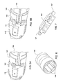
- Figures 6 and 7 illustrate a piston 140 and a blade 150, respectively.
- One or more grooves 143 are disposed along the inner diameter of the piston 140 for receiving the keys 147 and/or the arms 157 of the blades 150 for transmitting torque from the mandrel 105 to the blades 150.
- the one or more grooves 143 also permit longitudinal movement of the piston 140 relative to the keys 147 and/or the arms 157 of the blades 150.
- Each blade 150 may include one arm 157 at opposite ends, the arms 157 being integral with or coupled to the blades 150.
- the longitudinal edges of the blades 150 may be chamfered, and one or more helical grooves may be formed on the outer diameter of the blades 150 so that debris can be flushed out easily.
- One or more holes may also be formed on the inner diameter of the blades 150 and/or the outer diameter of the mandrel 105 for supporting and preventing longitudinal movement of the biasing members 155.
- Figures 8 and 9 illustrate sectional views of a cutting assembly 200 on different planes, respectively.
- the cutting assembly 200 may be used with the embodiments of the tool 10 described above.
- the components of the cutting assembly 200 that are substantially similar to the components of the cutting assembly 100 are identified with "200" series reference numbers and full descriptions of such components will not be repeated for brevity.
- the pistons 240 are releasably coupled to the housings 215 via one or more releasable members 245 to prevent premature actuation of the pistons 240 and retraction of the blades 250.
- the blades 250 may be located on the mandrel 205 using one or more rings or protrusions 207.
- the rings or protrusions 207 may be integral with or coupled to the blades 250, and may engage a groove or slot on the outer surface of the mandrel 205 to prevent longitudinal movement of the blades 250 and/or for transmitting torque to the blades 250.
- Torque may be transmitted from the mandrel 205 to the blades 250 via the pistons 240 and keys 247 and/or directly to the arms 257 of the blades 250.
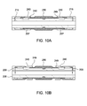
- Figure 10A illustrates the cutting assembly 200 in a run-in, extended position.
- the blades 250 are fully extended by the biasing members 255.
- the tool 10 may be rotated via a work string coupled to the top sub 110, which is coupled to the mandrel 205.
- Figure 10B illustrates the cutting assembly 200 in a retrieval, retracted position.
- the blades 250 are retracted by actuation of the pistons 240.
- Tapered surfaces at the ends of the pistons 240 contact taper surfaces on the blades 250 at interface 249.
- pressurized fluid is applied to the pistons 240 through one or more ports 209 in the mandrel 205 with enough force to shear the releasable members 245.
- One or more seals such as o-rings, may be used to seal fluid flow through the tool 10 and to the pistons 240 as known in the art.
- the pistons 240 are then moved longitudinally toward the blades 250 such that the tapered surfaces at interface 249 engage and force the blades 250 radially inward toward the mandrel 205 against the bias of the biasing members 255.
- the pistons 240 may be locked from movement in the opposite direction using the locking feature described above with respect to Figures 5A and 5B .
- Figures 11 and 12 illustrate a piston 240 and a blade 250, respectively.
- One or more grooves 243 are disposed along the inner diameter of the piston 240 for receiving the keys 247 and/or the arms 257 of the blades 250 for transmitting torque from the mandrel 205 to the blades 250.
- Each blade 250 may include two arms 257 at opposite ends, the arms 257 being integral with or coupled to the blades 250.
- one or more windows may be formed in the pistons 240 so that debris can be flushed out easily.
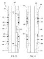
- Figures 13 and 14 illustrate sectional views of a cutting assembly 300 on different planes, respectively.
- the cutting assembly 300 may be used with the embodiments of the tool 10 described above.
- the components of the cutting assembly 300 that are substantially similar to the components of the cutting assembly 100 are identified with "300" series reference numbers and full descriptions of such components will not be repeated for brevity.
- the cutting assembly 300 is initially run-in with the blades 350 retracted, then actuated to move the blades 350 radially outward into an extended position, and then actuated again to move the blades 350 radially inward into a retracted position.
- the blades 350 are retracted in the run-in position.
- the biasing members 355 are positioned between the housings 315 and the blades 350 to bias the blades 350 radially inward toward the mandrel 305 into the retracted position.
- the pistons 340 are releasably coupled to the housings 315 via one or more first releasable members 345 to prevent premature actuation of the pistons 340 and outward actuation of the blades 350 into the extended position.
- the pistons 340 are temporarily prevented from movement toward the blades 350 by one or more second releasable members 344, after the first releasable members 345 are sheared, to prevent premature actuation of the pistons 340 and retraction of the blades 350 into the retracted position.
- the blades 350 may be located on the mandrel 305 using one or more rings or protrusions 307.
- the rings or protrusions 307 may be integral with or coupled to the blades 350, and may engage a groove or slot on the outer surface of the mandrel 305 to prevent longitudinal movement of the blades 350. Torque may be transmitted from the mandrel 305 to the blades 350 via the rings or protrusions 307.
- Figure 15A illustrates the cutting assembly 300 in an actuated, extended position.
- tapered surfaces at the ends of the pistons 340 contact taper surfaces on the arms 357 of the blades 350 at interface 349.
- a first closure member such as an extrudable ball or dart
- pressurized fluid is applied to the pistons 340 through one or more ports 309 in the mandrel 305 with enough force to shear the first releasable members 345 (but not the second releasable members 344).
- One or more seals such as o-rings, may be used to seal fluid flow through the tool 10 and to the pistons 340 as known in the art.
- the pistons 340 are then moved longitudinally toward the blades 350 such that the tapered surfaces at interface 349 engage and force the blades 350 radially outward away from the mandrel 305 and against the bias of the biasing members 355.
- the travel of the pistons 340 is limited by contacting the second releasable members 344.
- the tapered surfaces between the pistons 340 and the blades 350 are engaged such that the blades 350 are forced radially outward into contact with the wellbore tubular.
- Pressurized fluid may be used to extrude the first closure member and reestablish fluid circulation through the tool 10.
- the tool 10 may be rotated via a work string coupled to the top sub 110, which is coupled to the mandrel 305 for conducting a milling operation.
- Figure 15B illustrates the cutting assembly 300 in a retracted position.
- the blades 350 are retracted by further actuation of the pistons 340.
- a second closure member such as an extrudable ball or dart
- pressurized fluid is applied to the pistons 340 through one or more ports 309 in the mandrel 305 with enough force to shear the second releasable members 344.
- the pistons 340 then continue to move longitudinally toward the blades 350 such that the tapered surfaces on the arms 357 of the blades 350 drop into a groove or slot on the outer diameter of the piston 340.
- the biasing members 355 assist in forcing the blades 350 radially inward toward the mandrel 305.
- the pistons 340 may be locked from movement in the opposite direction by engagement with the arms 357 of the blades 350, and/or by using the locking feature described above with respect to Figures 5A and 5B .
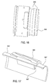
- Figures 16 and 17 illustrate a piston 340 and a blade 350, respectively,.
- One or more grooves 343 are disposed along the outer diameter of the piston 340 for engagement with the arms 357 of the blades 350 for actuation and retraction.
- Each blade 350 may include arms 357 at opposite ends, the arms 357 being integral with or coupled to the blades 350.
- Torque may be transmitted from the mandrel 305 to the blades 350 via the rings or protrusions 307.
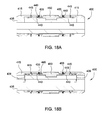
- Figures 18A and 18B illustrate sectional views of a cutting assembly 400 in a retracted position and an extended position, respectively.
- the cutting assembly 400 may be used with the embodiments of the tool 10 described above.
- the components of the cutting assembly 400 that are substantially similar to the components of the cutting assembly 100 are identified with "400" series reference numbers and full descriptions of such components will not be repeated for brevity.
- the blades 450 are retracted in the run-in position.
- the biasing members 455 are positioned between the housings 415 and the blades 450 to bias the blades 450 radially inward toward the mandrel 405 into the retracted position.
- the pistons 440 are releasably coupled to the housings 415 via one or more releasable members 445 to prevent premature actuation of the pistons 440 and outward actuation of the blades 450.
- tapered surfaces at the ends of the pistons 440 contact taper surfaces on the arms 457 of the blades 450 at interface 449.
- a closure member such as an extrudable ball or dart
- pressurized fluid is applied to the pistons 440 through one or more ports 409 in the mandrel 405 with enough force to shear the releasable members 445.
- seals such as o-rings, may be used to seal fluid flow through the tool 10 and to the pistons 440 as known in the art.
- the pistons 440 are then moved longitudinally toward the blades 450 such that the tapered surfaces at interface 349 engage and force the blades 450 radially outward away from the mandrel 405 against the bias of the biasing members 455 into the extended position for contact with the surrounding wellbore tubular.
- Torque may be transmitted from the mandrel 405 to the blades 450 via the rings or protrusions 407 that are integral with or coupled to the blades 450.
- the tool 10 may be rotated via a work string coupled to the top sub 110, which is coupled to the mandrel 405 for conducting a milling operation. After the milling operation is complete, fluid pressure in the tool 10 may be released, and the blades 450 may be retracted by the force of the biasing members 455. The force of the biasing members 455 on the blades 450 also move the pistons 440 back in the opposite direction into the retracted position for subsequent operation of the tool 10 and/or other wellbore operations.
- Figure 19 illustrates a sectional view of a cutting assembly 500.
- the cutting assembly 500 may be used with the embodiments of the tool 10 described above.
- the components of the cutting assembly 500 that are substantially similar to the components of the cutting assembly 100 are identified with "500" series reference numbers and full descriptions of such components will not be repeated for brevity.
- the top sub 110 may be coupled to housing 515 and mandrel 505.
- the top sub 110 and the housing 515 may be integral with each other and formed as a unitary sub.
- the top sub 110 and/or housing 515 may engage and transmit torque to the blades 550.
- An inner sleeve 520 may be disposed internal to the mandrel 505, in the flow bore of the mandrel 505 for receiving a closure member 590, such as an extrudable ball or dart.
- the inner sleeve 520 may be connected to an outer sleeve 540, disposed external to the mandrel 505, by one or more keys 597.
- the keys 597 may be axially movable within one or more slots 509 of the mandrel 505 and may axially couple the inner sleeve 520 to the outer sleeve 540.
- the keys 597 may permit rotation of the inner sleeve 520 and the mandrel 505 relative to the outer sleeve 540.
- the outer sleeve 540 may be coupled to the blades 550 via one or more set screws 517.
- FIG 20A illustrates the cutting assembly 500 in a run-in, activated position.
- the blades 550 may be fully extended outward and ready for conducting a milling operation by rotation of a work string supporting the tool 10.
- Rotation of the top sub 110 via the work string rotates the housing 515, which rotates the blades 550.
- closure member 590 may be dropped onto seat 595 of the inner sleeve 520 to close fluid flow through the end of the tool 10 and move the cutting assembly 500 to a deactivated position.
- Figure 20B illustrates the cutting assembly 500 in a deactivated position.
- Pressurized fluid is applied to the closure member 590 and the inner sleeve 520 with enough force to move the inner sleeve 520 in a downward direction, away from the top sub 110.
- One or more seals such as o-rings, may be used to seal fluid flow through the tool 10 and the inner sleeve 520 as known in the art.
- the axial force applied to the inner sleeve 520 pushes or forces the outer sleeve 540 away from the top sub 110 via the key 597 connection.
- the outer sleeve 540 pulls or forces the blades 550 away from the top sub 110 via the set screw 517 connection, which moves the blades 550 out of engagement with the housing 515. Travel of the outer sleeve 540 may be limited by the key 597 contacting the end of the slot 509 in the mandrel 505. Fluid circulation may be reestablished by extruding the closure member 590 through the seat 595, and/or flowing fluid around the closure member 590 and through one or more ports in the inner sleeve 520 for flow out the end of the tool 10.
- the blades 550 are deactivated by being rotationally decoupled from the housing 515, the top sub 110, and the mandrel 505. Rotation of the top sub 110 rotates the housing 515 but not the blades 550, which are no longer engaged with the housing 515. Rotation of the top sub 110 rotates the mandrel 505, the inner sleeve 520, and the keys 597, but not the outer sleeve 540 or the blades 550 since the keys 590 move within a circumferential groove or slot in the outer sleeve 540.
- the outer sleeve 540 may be locked from movement in the opposite direction using the locking feature described above with respect to Figures 5A and 5B .
- the torque transmission to the blades 550 may be provided by the inner and outer sleeves 520, 540 via keys 597; and the outer sleeve 540 may be moved out of engagement with the blades 550 (e.g. a spline engagement as opposed to set screws 517) by the closure member 590 and pressurized fluid operation described above to decouple torque transmission to the blades 550.
- Figures 21 and 22 illustrate the housing 515 and a blade 550, respectively, according to one embodiment.
- One or more grooves 543 are disposed along the inner diameter of the housing 515 for engagement with one or more rings or protrusions 507 that are coupled to or integral with the arm 557A of the blades 550 for torque transmission.
- Each blade 550 may include arm 557B at an opposite end having a shoulder for engagement with set screws 517 and connection to the outer sleeve 540.
- the embodiments of the cutting assemblies 100, 200, 300, 400, and 500 described herein may be combined and/or interchanged (in whole or part) with each other to form one or more additional embodiments, all of which may be used with the tool 10.
- One or more of the components of the cutting assemblies 100, 200, 300, 400, and 500, and tool 10 may be formed from metallic and/or drillable materials as known in the art.
- One or more of the components of the cutting assemblies 100, 200, 300, 400, and 500, and tool 10 may be sealed using o-rings or other types of seals as known in the art.
- One or more of the components of the cutting assemblies 100, 200, 300, 400, and 500, and tool 10 may be formed integral with each other or coupled together using one or more connections as known in the art.
- a wellbore tool comprising a top sub and a cutting assembly.
- the cutting assembly comprises: a mandrel in fluid communication with the top sub; a piston disposed external to the mandrel; a cutting member selectively movable into at least one of a retracted position and an extended position using the piston; and a bottom sub operable to close fluid flow through the tool.
- the mandrel may include one or more ports to provide fluid communication between a flow bore of the mandrel and the piston.
- the piston may be coupled to the mandrel using one or more releasable members.
- the piston may include a tapered surface movable into engagement with a tapered surface of the cutting member to move the cutting member into at least one of the retracted position and the extended position.
- the bottom sub may include a seat for receiving an extrudable closure member for closing fluid flow through the tool.
- the tool may further comprise one or more keys for transmitting torque from the mandrel to at least one of the piston and the cutting member, and/or a locking member operable to prevent movement of the piston in an opposite direction after the piston moves in a first direction to actuate the cutting member into at least one of the retracted position and the extended position.
- the tool may further comprise one or more biasing members for biasing the cutting member into at least one of the retracted position and the extended position.
- the method comprises: lowering the tool into a tubular using a work string; rotating a cutting assembly of the tool to remove irregularities from an inner surface of the tubular, wherein the cutting assembly comprises a mandrel, a piston, and a cutting member; and actuating the cutting member into at least one of a retracted position and an extended position using the piston, wherein the piston is disposed external to the mandrel.
- the method may further comprise one or more of the following features: supplying pressurized fluid through one or more ports of the mandrel to actuate the piston; releasing one or more releasable members to move the piston relative to the mandrel and actuate the cutting member; moving a tapered surface of the piston into engagement with a tapered surface of the cutting member to move the cutting member into at least one of the retracted position and the extended position; transmitting torque from the mandrel to at least one of the piston and the cutting member using one or more keys; using a locking member to prevent movement of the piston in an opposite direction after the piston moves in a first direction to actuate the cutting member into at least one of the retracted position and the extended position; flowing a closure member into engagement with a seat of the bottom sub to close fluid flow through the tool; extruding the closure member through the seat to open fluid flow through the tool; and biasing the cutting member into at least one of the retracted position and the extended position.
- a wellbore tool comprising a top sub and a cutting assembly.
- the cutting assembly comprises: a mandrel in fluid communication with the top sub; a sleeve coupled to the mandrel; and a cutting member selectively movable into a rotationally decoupled position using the sleeve.
- the top sub may be in engagement with the cutting member to transmit torque from the top sub to the cutting member.
- the sleeve may be disposed in a bore of the mandrel, and include a seat for receiving a closure member to close fluid flow through the bore of the mandrel.
- An outer sleeve may be axially coupled to the sleeve by one or more keys, wherein the outer sleeve is coupled to the cutting member.
- the cutting member may be movable out of engagement with the top sub using the outer sleeve to rotationally decouple the cutting member from the top sub.
- the sleeve may be movable using pressurized fluid to move the outer sleeve via the one or more keys to move the cutting member out of engagement with the top sub.
- a method of operating a well bore tool comprising: lowering the tool into a tubular using a work string; rotating a cutting assembly of the tool to remove irregularities from an inner surface of the tubular, wherein the cutting assembly comprises a mandrel, a sleeve, and a cutting member; and rotationally decoupling the cutting member from the mandrel using the sleeve.
- the tool may include a top sub for transmitting torque to the cutting member.
- the cutting assembly may further comprise an outer sleeve axially coupled to the sleeve by one or more keys, wherein the outer sleeve is coupled to the cutting member
- the method may further comprise one or more of the following features: flowing a closure member onto a seat of the sleeve to close fluid flow through the bore of the mandrel; moving the cutting member out of engagement with the top sub using the outer sleeve to rotationally decouple the cutting member from the top sub; and moving the sleeve using pressurized fluid to move the outer sleeve via the one or more keys to move the cutting member out of engagement with the top sub
- a wellbore tool locking assembly comprising a housing having a groove, a piston movable relative to the housing, and a locking element coupled to the piston.
- the piston is movable in one direction from a first position where the locking element is disposed in the groove to a second position where the locking element is removed from the groove, and wherein the locking element prevents movement of the piston in an opposite direction when removed from the groove.
- the locking element may be a flexible member that deflects radially inward when being moved out of the groove.
- the flexible member may extend radially outward when removed from the groove.
- the flexible member may engage the housing when removed from the groove to prevent movement of the piston in the opposite direction.
- the groove may be formed at an end of the housing.
- the groove may be a dovetail shaped groove.
Landscapes
- Engineering & Computer Science (AREA)
- Geology (AREA)
- Life Sciences & Earth Sciences (AREA)
- Mining & Mineral Resources (AREA)
- Environmental & Geological Engineering (AREA)
- Fluid Mechanics (AREA)
- Physics & Mathematics (AREA)
- General Life Sciences & Earth Sciences (AREA)
- Geochemistry & Mineralogy (AREA)
- Mechanical Engineering (AREA)
- Milling Processes (AREA)
- Milling, Broaching, Filing, Reaming, And Others (AREA)
- Turning (AREA)
- Auxiliary Devices For Machine Tools (AREA)
- Processing And Handling Of Plastics And Other Materials For Molding In General (AREA)
Applications Claiming Priority (1)
| Application Number | Priority Date | Filing Date | Title |
|---|---|---|---|
| US13/662,120 US9435176B2 (en) | 2012-10-26 | 2012-10-26 | Deburring mill tool for wellbore cleaning |
Publications (2)
| Publication Number | Publication Date |
|---|---|
| EP2725185A2 true EP2725185A2 (fr) | 2014-04-30 |
| EP2725185A3 EP2725185A3 (fr) | 2015-11-04 |
Family
ID=49448012
Family Applications (1)
| Application Number | Title | Priority Date | Filing Date |
|---|---|---|---|
| EP13189644.1A Withdrawn EP2725185A3 (fr) | 2012-10-26 | 2013-10-22 | Outil de fraisage d'ébavurage pour nettoyage de puits de forage |
Country Status (5)
| Country | Link |
|---|---|
| US (1) | US9435176B2 (fr) |
| EP (1) | EP2725185A3 (fr) |
| AU (1) | AU2013245515B2 (fr) |
| BR (1) | BR102013027615A8 (fr) |
| CA (2) | CA2830233C (fr) |
Cited By (1)
| Publication number | Priority date | Publication date | Assignee | Title |
|---|---|---|---|---|
| CN106639983A (zh) * | 2016-11-30 | 2017-05-10 | 中国海洋石油总公司 | 一种可变径套管刮管器 |
Families Citing this family (24)
| Publication number | Priority date | Publication date | Assignee | Title |
|---|---|---|---|---|
| GB2524788A (en) | 2014-04-02 | 2015-10-07 | Odfjell Partners Invest Ltd | Downhole cleaning apparatus |
| US9988878B2 (en) * | 2015-04-21 | 2018-06-05 | Baker Hughes, A Ge Company, Llc | One trip cleaning and tool setting in the cleaned location |
| US10641069B2 (en) | 2015-04-28 | 2020-05-05 | Thru Tubing Solutions, Inc. | Flow control in subterranean wells |
| US10233719B2 (en) | 2015-04-28 | 2019-03-19 | Thru Tubing Solutions, Inc. | Flow control in subterranean wells |
| US10513653B2 (en) | 2015-04-28 | 2019-12-24 | Thru Tubing Solutions, Inc. | Flow control in subterranean wells |
| US9567825B2 (en) | 2015-04-28 | 2017-02-14 | Thru Tubing Solutions, Inc. | Flow control in subterranean wells |
| US10655427B2 (en) * | 2015-04-28 | 2020-05-19 | Thru Tubing Solutions, Inc. | Flow control in subterranean wells |
| US11851611B2 (en) | 2015-04-28 | 2023-12-26 | Thru Tubing Solutions, Inc. | Flow control in subterranean wells |
| US9745820B2 (en) | 2015-04-28 | 2017-08-29 | Thru Tubing Solutions, Inc. | Plugging device deployment in subterranean wells |
| US9567826B2 (en) | 2015-04-28 | 2017-02-14 | Thru Tubing Solutions, Inc. | Flow control in subterranean wells |
| US10851615B2 (en) | 2015-04-28 | 2020-12-01 | Thru Tubing Solutions, Inc. | Flow control in subterranean wells |
| US10774612B2 (en) | 2015-04-28 | 2020-09-15 | Thru Tubing Solutions, Inc. | Flow control in subterranean wells |
| US9816341B2 (en) | 2015-04-28 | 2017-11-14 | Thru Tubing Solutions, Inc. | Plugging devices and deployment in subterranean wells |
| US9567824B2 (en) | 2015-04-28 | 2017-02-14 | Thru Tubing Solutions, Inc. | Fibrous barriers and deployment in subterranean wells |
| GB2538742B (en) * | 2015-05-27 | 2021-05-12 | Odfjell Partners Invest Ltd | Downhole milling tool |
| US11761295B2 (en) | 2015-07-21 | 2023-09-19 | Thru Tubing Solutions, Inc. | Plugging device deployment |
| WO2017014820A1 (fr) | 2015-07-21 | 2017-01-26 | Thru Tubing Solutions, Inc. | Déploiement de dispositif de colmatage |
| US10107077B2 (en) | 2015-12-08 | 2018-10-23 | Troy Settle | Well cleaning system |
| WO2018226237A1 (fr) * | 2017-06-09 | 2018-12-13 | Weatherford Technology Holdings, Llc | Racleur de tubage activé et désactivé en fond de trou |
| GB201802223D0 (en) | 2018-02-12 | 2018-03-28 | Odfjell Partners Invest Ltd | Downhole cleaning apparatus |
| GB2591644B (en) * | 2018-10-30 | 2022-08-31 | Halliburton Energy Services Inc | Rotating/non-rotating casing cleaning tool |
| US11047210B2 (en) | 2018-10-31 | 2021-06-29 | Weatherford Technology Holdings, Llc | Bottom hole assembly with a cleaning tool |
| RU2701401C1 (ru) * | 2019-02-06 | 2019-09-26 | Общество с ограниченной ответственностью "Научно-производственная фирма Завод "Измерон"" | Устройство очистки и промывки скважины с механическим преобразованием поступательного перемещения во вращательное движение |
| CN116927722B (zh) * | 2023-08-05 | 2024-05-10 | 东北石油大学 | 油管清蜡除垢方法以及用于实施该方法的组件和装置 |
Citations (3)
| Publication number | Priority date | Publication date | Assignee | Title |
|---|---|---|---|---|
| US20030079913A1 (en) * | 2000-06-27 | 2003-05-01 | Halliburton Energy Services, Inc. | Apparatus and method for drilling and reaming a borehole |
| US20100025116A1 (en) * | 2006-08-10 | 2010-02-04 | Richard Hutton | Steerable rotary directional drilling tool for drilling boreholes |
| EP2467555A2 (fr) * | 2009-08-21 | 2012-06-27 | Paul Bernard Lee | Appareil formant roulement à rouleaux expansible pour fond de trou |
Family Cites Families (33)
| Publication number | Priority date | Publication date | Assignee | Title |
|---|---|---|---|---|
| US2857141A (en) | 1957-04-25 | 1958-10-21 | Frank H Carpenter | Well tool |
| US4479538A (en) | 1981-06-22 | 1984-10-30 | Bilco Tools, Inc. | Casing scraper and method for making the same |
| US4693316A (en) * | 1985-11-20 | 1987-09-15 | Halliburton Company | Round mandrel slip joint |
| US5253714A (en) | 1992-08-17 | 1993-10-19 | Baker Hughes Incorporated | Well service tool |
| US5351758A (en) * | 1993-02-22 | 1994-10-04 | Pacific Well Services Ltd. | Tubing and profile reaming tool |
| GB9517829D0 (en) | 1995-09-01 | 1995-11-01 | Oiltools Int Bv | Tool for cleaning or conditioning tubular structures such as well casings |
| US5829521A (en) | 1997-02-21 | 1998-11-03 | Brown, Jr.; Billy L. | Down hole cleaning device and method |
| US6209647B1 (en) | 1997-02-21 | 2001-04-03 | Billy L. Brown, Jr. | Down hole casing string cleaning device and method |
| GB9803824D0 (en) | 1998-02-24 | 1998-04-22 | Specialised Petroleum Serv Ltd | Compact well clean-up tool with multi-functional cleaning apparatus |
| GB9813422D0 (en) | 1998-06-23 | 1998-08-19 | Specialised Petroleum Serv Ltd | Down-hole tool with detachable cleaning pads |
| GB2340150B (en) | 1998-08-03 | 2002-09-18 | Smith International | Downhole scraper assembly |
| US6464010B1 (en) | 1998-08-13 | 2002-10-15 | Global Completion Services, Inc. | Apparatus and method for cleaning a tubular member with a brush |
| GB9902595D0 (en) | 1999-02-08 | 1999-03-24 | Specialised Petroleum Serv Ltd | Apparatus with retractable cleaning members |
| GB2347442B (en) | 1999-03-03 | 2003-03-26 | Pilot Drilling Control Ltd | Casing scraper |
| US6347667B1 (en) | 1999-10-26 | 2002-02-19 | Specialized Petroleum Services Ltd. | Well clean-up tool with improved cleaning member |
| GB0125306D0 (en) | 2001-10-20 | 2001-12-12 | Sps Afos Group Ltd | Disengagable burr mill |
| US6851472B2 (en) | 2002-03-13 | 2005-02-08 | Baker Hughes Incorporated | Convertible tubular scraper |
| GB0210286D0 (en) | 2002-05-04 | 2002-06-12 | Sps Afos Group Ltd | Selectively operational cleaning tool |
| US6883605B2 (en) | 2002-11-27 | 2005-04-26 | Offshore Energy Services, Inc. | Wellbore cleanout tool and method |
| CA2507778A1 (fr) | 2002-12-12 | 2004-07-01 | Albert Augustus Mullins | Nettoyage de puits de forage et circulation de tubage et appareil de reflux |
| GB0306821D0 (en) | 2003-03-25 | 2003-04-30 | Specialised Petroleum Serv Ltd | Dual function cleaning tool |
| MXPA05011451A (es) | 2003-04-25 | 2005-12-12 | Regent Technologies Ltd | Aparato y metodo para desbarbado termico de revestimientos ranurados de pozos. |
| GB0309906D0 (en) * | 2003-04-30 | 2003-06-04 | Andergauge Ltd | Downhole tool |
| CA2499532C (fr) | 2004-03-11 | 2012-11-20 | Smith International, Inc. | Gratte-paroi |
| GB0513645D0 (en) | 2005-07-02 | 2005-08-10 | Specialised Petroleum Serv Ltd | Wellbore cleaning method and apparatus |
| MX2009006399A (es) | 2006-12-12 | 2009-11-26 | Wellbore Energy Solutions Llc | Herramienta mejorada de cepillado y/o raspadura de fondo del pozo y metodos relacionados. |
| NO347018B1 (no) | 2007-07-06 | 2023-04-11 | Halliburton Energy Services Inc | Flerbruks brønnserviceanordning |
| US8826986B2 (en) | 2007-10-03 | 2014-09-09 | M-I L.L.C. | Downhole scraper |
| US8141628B2 (en) | 2007-12-31 | 2012-03-27 | Precision Energy Services, Inc. | Downhole deburring tool |
| US8540035B2 (en) | 2008-05-05 | 2013-09-24 | Weatherford/Lamb, Inc. | Extendable cutting tools for use in a wellbore |
| US8905126B2 (en) * | 2009-03-26 | 2014-12-09 | Baker Hughes Incorporated | Expandable mill and methods of use |
| US8141627B2 (en) | 2009-03-26 | 2012-03-27 | Baker Hughes Incorporated | Expandable mill and methods of use |
| EP2483510A2 (fr) | 2009-09-30 | 2012-08-08 | Baker Hughes Incorporated | Appareil telecommande pour applications de fond de puits et procedes d'exploitation |
-
2012
- 2012-10-26 US US13/662,120 patent/US9435176B2/en active Active
-
2013
- 2013-10-16 CA CA2830233A patent/CA2830233C/fr not_active Expired - Fee Related
- 2013-10-16 CA CA2938243A patent/CA2938243C/fr not_active Expired - Fee Related
- 2013-10-17 AU AU2013245515A patent/AU2013245515B2/en not_active Ceased
- 2013-10-22 EP EP13189644.1A patent/EP2725185A3/fr not_active Withdrawn
- 2013-10-25 BR BR102013027615A patent/BR102013027615A8/pt not_active IP Right Cessation
Patent Citations (3)
| Publication number | Priority date | Publication date | Assignee | Title |
|---|---|---|---|---|
| US20030079913A1 (en) * | 2000-06-27 | 2003-05-01 | Halliburton Energy Services, Inc. | Apparatus and method for drilling and reaming a borehole |
| US20100025116A1 (en) * | 2006-08-10 | 2010-02-04 | Richard Hutton | Steerable rotary directional drilling tool for drilling boreholes |
| EP2467555A2 (fr) * | 2009-08-21 | 2012-06-27 | Paul Bernard Lee | Appareil formant roulement à rouleaux expansible pour fond de trou |
Non-Patent Citations (1)
| Title |
|---|
| None |
Cited By (2)
| Publication number | Priority date | Publication date | Assignee | Title |
|---|---|---|---|---|
| CN106639983A (zh) * | 2016-11-30 | 2017-05-10 | 中国海洋石油总公司 | 一种可变径套管刮管器 |
| CN106639983B (zh) * | 2016-11-30 | 2018-12-14 | 中国海洋石油集团有限公司 | 一种可变径套管刮管器 |
Also Published As
| Publication number | Publication date |
|---|---|
| CA2830233C (fr) | 2018-01-02 |
| AU2013245515A1 (en) | 2014-05-15 |
| US20140116712A1 (en) | 2014-05-01 |
| CA2830233A1 (fr) | 2014-04-26 |
| CA2938243A1 (fr) | 2014-04-26 |
| CA2938243C (fr) | 2017-02-07 |
| US9435176B2 (en) | 2016-09-06 |
| BR102013027615A8 (pt) | 2016-03-08 |
| AU2013245515B2 (en) | 2016-02-25 |
| BR102013027615A2 (pt) | 2014-12-23 |
| EP2725185A3 (fr) | 2015-11-04 |
Similar Documents
| Publication | Publication Date | Title |
|---|---|---|
| CA2830233C (fr) | Outil de fraisage et d'ebavurage pour nettoyage de puits de forage | |
| CA2924287C (fr) | Outil de fond de trou recuperable | |
| US10513901B2 (en) | Downhole tool for removing a casing portion | |
| EP2094934B1 (fr) | Tête de coupe élargisseur avec dispositif de réception d'élément d'étranglement et élément de déclenchement et procédé d'activation | |
| US10526849B2 (en) | Cutting structure with blade having multiple cutting edges | |
| US20150354306A1 (en) | Downhole tool with expandable stabilizer and underreamer | |
| US10648289B2 (en) | Downhole milling tool | |
| DK180668B1 (en) | Expandable seal | |
| WO2013028946A1 (fr) | Stabilisateur hydraulique destiné à être utilisé avec un dispositif de coupe de tubage de fond de trou | |
| EP3014046B1 (fr) | Stabilisateur | |
| US10458196B2 (en) | Downhole casing pulling tool | |
| US10815745B2 (en) | Thru-casing section mill | |
| US11619100B2 (en) | Expandable cutting tool | |
| US20240093561A1 (en) | Milling Tool |
Legal Events
| Date | Code | Title | Description |
|---|---|---|---|
| PUAI | Public reference made under article 153(3) epc to a published international application that has entered the european phase |
Free format text: ORIGINAL CODE: 0009012 |
|
| 17P | Request for examination filed |
Effective date: 20131022 |
|
| AK | Designated contracting states |
Kind code of ref document: A2 Designated state(s): AL AT BE BG CH CY CZ DE DK EE ES FI FR GB GR HR HU IE IS IT LI LT LU LV MC MK MT NL NO PL PT RO RS SE SI SK SM TR |
|
| AX | Request for extension of the european patent |
Extension state: BA ME |
|
| RAP1 | Party data changed (applicant data changed or rights of an application transferred) |
Owner name: WEATHERFORD/LAMB, INC. |
|
| RAP1 | Party data changed (applicant data changed or rights of an application transferred) |
Owner name: WEATHERFORD TECHNOLOGY HOLDINGS, LLC |
|
| PUAL | Search report despatched |
Free format text: ORIGINAL CODE: 0009013 |
|
| AK | Designated contracting states |
Kind code of ref document: A3 Designated state(s): AL AT BE BG CH CY CZ DE DK EE ES FI FR GB GR HR HU IE IS IT LI LT LU LV MC MK MT NL NO PL PT RO RS SE SI SK SM TR |
|
| AX | Request for extension of the european patent |
Extension state: BA ME |
|
| RIC1 | Information provided on ipc code assigned before grant |
Ipc: E21B 10/32 20060101AFI20150928BHEP Ipc: E21B 23/04 20060101ALI20150928BHEP Ipc: E21B 37/02 20060101ALI20150928BHEP Ipc: E21B 37/00 20060101ALI20150928BHEP Ipc: E21B 29/00 20060101ALI20150928BHEP |
|
| STAA | Information on the status of an ep patent application or granted ep patent |
Free format text: STATUS: EXAMINATION IS IN PROGRESS |
|
| 17Q | First examination report despatched |
Effective date: 20181108 |
|
| STAA | Information on the status of an ep patent application or granted ep patent |
Free format text: STATUS: THE APPLICATION IS DEEMED TO BE WITHDRAWN |
|
| 18D | Application deemed to be withdrawn |
Effective date: 20190319 |