EP2724327B1 - Security system tag magnetic clutch and method - Google Patents
Security system tag magnetic clutch and method Download PDFInfo
- Publication number
- EP2724327B1 EP2724327B1 EP12732752.6A EP12732752A EP2724327B1 EP 2724327 B1 EP2724327 B1 EP 2724327B1 EP 12732752 A EP12732752 A EP 12732752A EP 2724327 B1 EP2724327 B1 EP 2724327B1
- Authority
- EP
- European Patent Office
- Prior art keywords
- magnetic
- clamp
- keyed
- tag
- magnet
- Prior art date
- Legal status (The legal status is an assumption and is not a legal conclusion. Google has not performed a legal analysis and makes no representation as to the accuracy of the status listed.)
- Active
Links
Images

Classifications
-
- E—FIXED CONSTRUCTIONS
- E05—LOCKS; KEYS; WINDOW OR DOOR FITTINGS; SAFES
- E05B—LOCKS; ACCESSORIES THEREFOR; HANDCUFFS
- E05B73/00—Devices for locking portable objects against unauthorised removal; Miscellaneous locking devices
- E05B73/0017—Anti-theft devices, e.g. tags or monitors, fixed to articles, e.g. clothes, and to be removed at the check-out of shops
- E05B73/0047—Unlocking tools; Decouplers
- E05B73/0052—Unlocking tools; Decouplers of the magnetic type
-
- G—PHYSICS
- G08—SIGNALLING
- G08B—SIGNALLING OR CALLING SYSTEMS; ORDER TELEGRAPHS; ALARM SYSTEMS
- G08B13/00—Burglar, theft or intruder alarms
- G08B13/02—Mechanical actuation
- G08B13/14—Mechanical actuation by lifting or attempted removal of hand-portable articles
- G08B13/1445—Mechanical actuation by lifting or attempted removal of hand-portable articles with detection of interference with a cable tethering an article, e.g. alarm activated by detecting detachment of article, breaking or stretching of cable
- G08B13/1463—Physical arrangements, e.g. housings
-
- G—PHYSICS
- G08—SIGNALLING
- G08B—SIGNALLING OR CALLING SYSTEMS; ORDER TELEGRAPHS; ALARM SYSTEMS
- G08B13/00—Burglar, theft or intruder alarms
- G08B13/22—Electrical actuation
- G08B13/24—Electrical actuation by interference with electromagnetic field distribution
- G08B13/2402—Electronic Article Surveillance [EAS], i.e. systems using tags for detecting removal of a tagged item from a secure area, e.g. tags for detecting shoplifting
- G08B13/2428—Tag details
- G08B13/2434—Tag housing and attachment details
-
- G—PHYSICS
- G08—SIGNALLING
- G08B—SIGNALLING OR CALLING SYSTEMS; ORDER TELEGRAPHS; ALARM SYSTEMS
- G08B13/00—Burglar, theft or intruder alarms
- G08B13/22—Electrical actuation
- G08B13/24—Electrical actuation by interference with electromagnetic field distribution
- G08B13/2402—Electronic Article Surveillance [EAS], i.e. systems using tags for detecting removal of a tagged item from a secure area, e.g. tags for detecting shoplifting
- G08B13/2451—Specific applications combined with EAS
- G08B13/246—Check out systems combined with EAS, e.g. price information stored on EAS tag
-
- Y—GENERAL TAGGING OF NEW TECHNOLOGICAL DEVELOPMENTS; GENERAL TAGGING OF CROSS-SECTIONAL TECHNOLOGIES SPANNING OVER SEVERAL SECTIONS OF THE IPC; TECHNICAL SUBJECTS COVERED BY FORMER USPC CROSS-REFERENCE ART COLLECTIONS [XRACs] AND DIGESTS
- Y10—TECHNICAL SUBJECTS COVERED BY FORMER USPC
- Y10T—TECHNICAL SUBJECTS COVERED BY FORMER US CLASSIFICATION
- Y10T70/00—Locks
- Y10T70/50—Special application
- Y10T70/5009—For portable articles
Definitions
- the present invention relates generally to security systems and more specifically to a security tag having a magnetic clamp where the security tag may only be unlocked using a detacher that supplies a magnetic field with a specific polarity pattern.
- EAS Electronic article surveillance
- EAS tags are designed to interact with an electromagnetic field located at the exits of the controlled area, such as a retail store. These EAS tags are attached to the articles to be protected. If an activated EAS tag is brought into the electromagnetic field or "detection zone,” the presence of the tag is detected and appropriate action is taken, such as generating an alarm. For authorized removal of the article, the EAS tag can be deactivated, removed or passed around the electromagnetic field to prevent detection by the EAS system.
- Radio-frequency identification (“RFID”) systems are also generally known in the art and may be used for a number of applications, such as managing inventory, electronic access control, security systems, and automatic identification of cars on toll roads.
- An RFID system typically includes an RFID reader and an RFID device.
- the RFID reader may transmit a radio-frequency (“RF") carrier signal to the RFID device.
- the RFID device may respond to the carrier signal with a data signal encoded with information stored by the RFID device.
- Reusable tags whether they are EAS, RFID, combination EAS/RFID, or other types of security tags, are typically removed from their articles before the customer exits the store.
- the security tags are affixed to their article by a locking mechanism such as a clamp that retains an attachment element such as a pin, which prevents the article from unauthorized removal from the store.
- a locking mechanism such as a clamp that retains an attachment element such as a pin, which prevents the article from unauthorized removal from the store.
- One type of clamp is a magnetic clamp that can be unlocked by a permanent magnet in a detacher unit. This disengages the attachment pin in the tag to allow the article to be removed.
- the locking mechanism (such as a moving clamp or pin) is usually made with a magnetic material such as carbon steel. Upon exposure to a magnetic field from a detacher unit, part of the clamp is attracted to the detacher. This magnetic force is used to unlock the pin from the tag housing thus allowing the item to which the tag was attached to be removed from the store without setting off an alarm.
- the tag's clamp is typically designed such that it can only be opened when exposed to an unusually high magnetic field.
- detacher designers have created detacher units having a magnetic structure that are capable of producing high field strength.
- the present invention advantageously provides a magnetic security tag for use in securing an item in order to prevent the unauthorized removal of the item.
- the magnetic tag includes a clamp having a locking region that secures an attachment element such that the item cannot be separated from the tag.
- a keyed magnetic element situated on the clamp includes a plurality of hard magnets, where each hard magnet has either an outward-facing north or south polarity.
- the arrangement of magnets operates as a "key" and only a detacher unit with a corresponding attracting or repelling keyed magnetic pattern can apply the requisite magnetic force to the clamp magnets to disengage the attachment element from the item. By applying a magnetic force on the magnets, the locking region moves away from the attachment element thus allowing the tag to be removed from the item.
- a magnetic clamping device for securing an attachment element to an item is provided, according to claim 1.
- the magnetic clamping device includes a clamp movable between a locked position and an unlocked position and a keyed magnetic element affixed to the clamp. The clamp moves from the locked position to the unlocked position when a keyed magnetic force corresponding to the keyed magnetic element is applied to the keyed magnetic element.
- a security tag in another aspect, is provided, according to claim 8, where the security tag includes an attachment element.
- a housing has an attachment region and a clamping region.
- the attachment region is adapted to receive at least a portion of the attachment element.
- a clamp is within the clamping region.
- the clamp is movable between a locked position and an unlocked position.
- a keyed magnetic element is affixed to the clamp. The clamp moves from the locked position to the unlocked position when a keyed magnetic force corresponding to the keyed magnetic element is applied to the keyed magnetic element.
- a security system in which the security system includes a security tag and a tag detacher.
- the security tag includes a clamping device.
- the clamping device has a clamp movable between a locked position and an unlocked position.
- a keyed magnetic element is affixed to the clamp.
- the keyed magnetic element having a magnetic polarity pattern.
- the tag detacher includes a magnetic region. The magnetic region applies, to the keyed magnetic element, a keyed magnetic force corresponding to that keyed magnetic element. The magnetic force moves the clamp from the locked position to the unlocked position.
- the embodiments reside primarily in combinations of apparatus components related to providing a tag having a magnetic clamp for use in securing an item in order to prevent the unauthorized removal of the item.
- relational terms such as “first” and “second,” “top” and “bottom,” and the like, may be used solely to distinguish one entity or element from another entity or element without necessarily requiring or implying any physical or logical relationship or order between such entities or elements.
- the magnetic tag advantageously provides a magnetic tag for use in securing an item, such as an article of clothing, in order to prevent the unauthorized removal of the item from, for example, a retail store.
- the magnetic tag includes an attachment element, such as a pin, or lanyard, that secures the item to the tag.
- a clamp having a pivoting or sliding portion secures the attachment element such that the item cannot be separated from the tag.
- a magnetic element is affixed to the clamp, and includes one or more hard magnets, where each hard magnet has either a north or south polarity.
- the arrangement of magnets operates as a "key" and only a detacher unit with a corresponding magnetic pattern can apply the magnetic attracting or repelling force to the magnets to disengage the attachment element from the tag.
- the pivoting or sliding portion moves away from the attachment element thus allowing the attachment element to be removed from the tag.
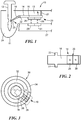
- FIG. 1 an exemplary configuration of a magnetic tag 10 used in accordance with the principles of the present invention.
- Tag 10 can be any security tag including a tag having electronic article surveillance (“EAS”), alarming, and/or radio frequency identification (“RFID”) elements.
- FIG. 1 shows tag 10 having an attachment element 12 which is shown in FIG. 1 as a pin. Attachment element 12 secures tag 10 to an item, such as an article of clothing (not shown). If the item is removed from within a specified region, such as a retail store, without removal of tag 10, an alarm will be actuated signaling the unauthorized removal of the item.
- EAS electronic article surveillance
- RFID radio frequency identification
- Attachment element 12 need not be a pin but can be any type of attachment device, such as a lanyard, a plunger or a plastic strap.
- Tag 10 includes a housing 11, and also includes a clamp 14 situated within a clamping region 13 in housing 11. EAS, RFID and/or alarming elements can be enclosed within the housing 11.
- Clamp 14 may be made of a magnetic material such as carbon steel or can be made of a non-magnetic material.
- Clamp 14 acts as a magnetic clutch and secures attachment element 12 within an attachment region 24, thus preventing the unauthorized separation of tag 10 from its item.
- Clamp 14 includes a locking region 16, a magnet location region 18, and a magnetic element 20.
- Spring 21 biases clamp 14 to allow retention of attachment element 12 and to allow return of clamp 14 to the locked position once the clamp has been unlocked.
- spring 21 is shown above clamp 14 so that operation of clamp 14 causes compression of spring 21, the invention is not limited to such.
- spring 21 can be placed below clamp 14 such that operation of claim 14 causes an expansion of spring 21.
- Locking region 16 and magnet location region 18 pivot about a pivot point 22, which allows locking region 16 to move between a first position and a second position.
- locking region 16 engages a circumferential détente 25 in attachment element 12, thus locking attachment element 12 in place within attachment region 24 of tag 10.
- attachment element 12 in this instance a pin, pierces the item, i.e., an article of clothing sandwiching the item between attachment element 12 and tag 10, which prevents the unauthorized separation of the item from tag 10.
- magnet location region 18 moves in the direction of the arrow in FIG.
- Magnetic element 20 includes at least one hard magnet affixed to one side of magnet location region 18 as shown in FIG. 1 .
- FIG. 1 also shows a detaching unit 27 used to detach tag 10 from its article.
- Detaching unit 27 includes one or more magnets 29 and 31 such that when detaching unit 27 is placed proximate tag 10, magnets 29 and 31 are aligned with the magnets of magnetic element 20 of tag 10. Due to the repelling force between magnets having identical outwards-facing poles, magnet location region 18 is forced in the direction of the arrow which in turn forces locking region 16 to pivot about pivot point 22. This disengages locking region 16 from within circumferential détente 25, which allows attachment element 12 to be removed from tag 10.
- magnetic element 20 of tag 10 has a magnetic arrangement forming a "key”.
- Detaching unit 27 must include magnets having the corresponding magnetic "key” in order to release attachment element 12 from tag 10.
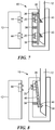
- FIG. 2 is a bottom view of clamp 14 and shows an exemplary magnetic element 20.
- magnet element 20 includes two magnets, a first magnet 26 having an outward-facing north magnet polarity and a second magnet 28 having an outward-facing south magnetic polarity.
- magnetic element 20 used with clamp 14 includes two magnets 26 and 28 arranged with opposite poles in a side-by-side, coplanar fashion, as shown. Magnets 26 and 28 can be physically separate magnets which thereby form two magnet domains, e.g. a north pole and a south pole, or a single physical magnet having two magnet domains, e.g., the north pole and south pole orientation shown in FIG. 1 is established on a single physical magnet.
- magnets of magnet element 20 can be made of bonded or sintered ceramic.
- the arrangement of magnets 26 and 28 shown in FIG. 2 is exemplary only and magnetic element 20 can include any number of magnets, arranged in any magnetic polarity pattern.
- the arrangement of magnets of magnetic element 20 forms a specific magnetic pattern or "key”.
- Introduction of an identical magnetic pattern in a magnetic detacher will repel magnets 26 and 28 of magnetic element 20.
- this repelling force will move body 18 in such a fashion that movable element 16 will pivot about pivot point 22 and will be dislodged from engagement with attachment element 12, thus allowing removal of attachment element 12 and freeing tag 10 from its item.
- magnetic detaching unit 27 may be used to detach magnetic tag 10 from its item.
- Magnetic detaching unit 27 has one or more magnets forming a magnetic region. The magnets are arranged such that they form a specific keyed magnetic polarity pattern or combination.
- FIG. 3 shows an exemplary magnetic pattern 30 formed from a magnetic detaching unit 27 using concentric ring magnets.
- An inner ring magnet 32 has its magnetic north pole facing up, i.e., toward a tag placement region, while an outer ring 34 has its magnetic the south pole pointing facing up.
- tag 10 is placed above the magnetic detaching unit 27 in the tag placement region.
- detaching unit 27 In order to detach tag 10, magnets in detaching unit 27 are aligned with magnets in tag 10 such that identical poles are aligned. In this fashion, a repelling force is generated upon magnets 26 and 28, which forces body 18 of clamp 14 upwards, as shown in FIG. 1 . This results in disengaging locking region 16 from attachment element 12 by moving the tip of locking region 16 away from circumferential détente 25 in attachment element 12. This will allow attachment element 12 to be removed from tag10.
- the length of clamp 14 can vary according to preferred design thus allowing the amount of necessary detaching force and torque to be controlled.
- the polarity arrangement shown in FIG. 3 is exemplary only.
- the outer ring may have an upward facing north magnetic polarity and the inner ring may have an upwards facing south magnetic polarity.
- the magnetic pattern of the detacher is designed to apply the requisite repelling force needed to unlock clamp 14. Further, since the number of magnets in magnetic element 20 can be greater than two, additional rings may be needed in the detacher's magnetic pattern.
- the present invention is not limited to a specific number of magnets used in clamp 14 or to a specific magnetic ring pattern formed by the magnetic detacher. In this fashion, the present invention advantageously prevents a shoplifter from detaching tag 10 from its item by simply using a large enough magnet upon tag 10. The shoplifter would have to know the precise magnetic pattern formed by magnetic element 20 and design a detacher having this exact pattern.
- tag 10 includes magnetic element 20 having two or more magnets sized in a fashion such that the housing of tag detacher 27 can be designed so tag 10 can only fit within detacher 27 in one way in order to assure the proper alignment of the magnets.
- tag 10 includes magnetic element 20 having two or more magnets sized in a fashion such that the housing of tag detacher 27 can be designed so tag 10 can only fit within detacher 27 in one way in order to assure the proper alignment of the magnets.
- a shoplifter uses his or her own detacher 27 in an attempt to detach tag 10 from its item, the necessary unlocking force or torque cannot be generated, since the force created from one-magnet will be cancelled by the other due to opposing poles.
- such a magnetic configuration provides a repelling force that is responsible for unlocking clamp 14. This is different from typical magnetic detaching mechanisms, which rely on the magnetic attraction between the detacher and the locking mechanism. Further, even if a shoplifter was clever, could obtain and assemble concentric
- FIG. 4 shows a magnetic tag detacher pattern 30 having two concentric ring magnets where the inner ring magnet 32 has an upward facing north magnetic polarity and the outer ring magnet 34 has an upward facing south magnetic polarity.
- FIG. 4 shows two magnets 26 and 28 within clamp 14 of tag 10. Clamp 14 is placed over the concentric ring configuration 30 of the magnetic detacher. In this instance, since the north magnetic polarity of magnet 26 is directly above the south magnetic polarity of inner ring 32 and the south magnetic polarity of magnet 28 is directly above the north magnetic polarity of outer ring 34, there is an attraction force that pulls clamp 14 in a downward direction, i.e., toward the tag placement region of detaching unit 27.
- FIG. 5 illustrates how the magnets of detaching unit 27 and the magnets of magnetic element 20 of tag 10 can be arranged to provide attractive forces to unlock clamp 14.
- FIG. 5 is a side view of the embodiment discussed above and shown in FIG. 4 .
- a repelling force is applied to magnets 26 and 28 of magnet element 20 and serves to pull clamp 14 downward in the direction shown in FIG. 5 , i.e., toward the tag placement region of detaching unit 27.
- pivot point 22 is now located at one end of clamp 20 rather than between locking region 16 and magnet location region 18 as in the configuration shown in FIG. 1 , and the magnets 26 and 28 or magnetic element 20 are reversed.
- spring 21 is situated proximate the point where locking region 16 joins magnet location region 18.
- magnet location region 18 is pulled downward as shown by the arrow in FIG. 5 .
- This force compresses spring 21, which moves locking region 16 away from attachment element 12 as shown by the arrow, thereby allowing tag 10 to be detached from the protected item.
- FIG. 6 illustrates another embodiment of the present invention where two clamps 14 are placed on either side of the attachment element 12.
- Affixed to one of the clamps 14 is a magnet 26 with an outward-facing southern polarity and affixed to the other clamp 14 is a magnet 28 with an outward-facing northern polarity, as shown.
- a detacher having uniform pole magnetization is used, e.g., two magnets having the same polarity, only one of clamps 14 is disengaged from attachment element 12 while the other clamp remains engaged with attachment element 12. The result is that attachment element 12 remains locked within tag 10.
- a detacher having an identical magnetization configuration as shown in FIG. 6 applies an upward force upon clamps 14 as shown by the arrows.
- FIG. 6 is exemplary only and only serves to illustrate that multiple clamps 14 and multiple magnetic patterns can be designed such that only a detacher having an identical magnetic pattern arrangement can successfully unlock tag 10.
- the present invention can utilize either repelling or attractive magnetic forces, and can incorporate one or more clamps 14 in order to design a tag detaching system that prevents unauthorized unlocking of magnetic tag 10.
- FIG. 7 shows another embodiment of the tag detacher system of the present invention.
- tag 10 includes a spring-loaded locking mechanism 36 with two sets of magnet elements 20.
- magnetic element 20 includes two magnets, although the number of magnets used can vary.
- Three springs 38 apply force upon locking mechanism 36. This force secures attachment element 12 within tag 10 due to the engagement of two prongs 40 within corresponding grooves within attachment element 12, as shown.
- a detacher 42 that includes magnet assembly 44, is positioned under tag 10 such that magnet assembly 44 are aligned with magnet elements 20.
- the polarities of the magnets of magnet assembly 44 are opposite the polarities of the magnets of magnet elements 20.
- the attractive force between the magnets of magnet assembly 44 and the magnets of magnet elements 20 withdraw prongs 40 of locking mechanism 36 from within corresponding grooves of attachment element 12, compresses springs 38, and allows attachment element 12 to be withdrawn from tag 10.
- FIG. 8 illustrates yet another embodiment of the present invention.
- locking mechanism 36 includes a hinge 46 in locking mechanism 36.
- Magnetic element 20 is situated toward one end of locking mechanism 36.
- magnets of magnet assembly 44 having identical polarities to the magnets of magnetic element 20 generate a repelling force that forces the top end of locking mechanism 36 toward attachment element 12. This allows locking mechanism 36 to pivot about hinge 46, which compresses spring 38. As spring 38 is compressed, prong 40 is withdrawn from within the groove 39 of attachment element 12 thus releasing attachment element 12 from tag 10.
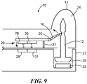
- FIG. 9 illustrates yet another embodiment of the present invention.
- the operator puts tag 10 on detaching unit 27 and has to manually remove attachment element 12, e.g., a pin or lanyard, with one hand while holding tag 10 with another.
- attachment element 12 e.g., a pin or lanyard
- both tasks can be accomplished with a single hand.
- a mechanism to capture the attachment element, e.g., pin 12 is integrated into detaching unit 27.
- clamp 14 is unlocked before pin 12 is captured. Otherwise, the locking mechanism may jam.
- detaching unit 27 includes an unlocking mechanism, which is supported by a spring loaded platform (not shown).
- Detaching unit 27 also includes a pin capturing magnet 33 which is located within a recess 35 of detacher unit 27.
- tag 10 is placed, pin-down, into detaching unit 27.
- Clamp 14 is unlocked as tag 10 is positioned in the manner described above in earlier embodiments, i.e., positioned to align magnets 26 and 28 in tag 10 with corresponding magnets 29 and 31 in detaching unit 27.
- the operator activates detaching until 27, causing pin 12 to be captured by pin capturing magnet 33. It is presumed that a portion of pin 12 has magnetic properties which allow it to be attracted to capturing magnet 33. Then, tag 10 can be removed from the protected article.
Description
- The present invention relates generally to security systems and more specifically to a security tag having a magnetic clamp where the security tag may only be unlocked using a detacher that supplies a magnetic field with a specific polarity pattern.
- Electronic article surveillance ("EAS") systems are generally known in the art for the prevention or deterrence of unauthorized removal of articles from a controlled area. In a typical EAS system, EAS tags, markers and labels (collectively "tags") are designed to interact with an electromagnetic field located at the exits of the controlled area, such as a retail store. These EAS tags are attached to the articles to be protected. If an activated EAS tag is brought into the electromagnetic field or "detection zone," the presence of the tag is detected and appropriate action is taken, such as generating an alarm. For authorized removal of the article, the EAS tag can be deactivated, removed or passed around the electromagnetic field to prevent detection by the EAS system.
- Radio-frequency identification ("RFID") systems are also generally known in the art and may be used for a number of applications, such as managing inventory, electronic access control, security systems, and automatic identification of cars on toll roads. An RFID system typically includes an RFID reader and an RFID device. The RFID reader may transmit a radio-frequency ("RF") carrier signal to the RFID device. The RFID device may respond to the carrier signal with a data signal encoded with information stored by the RFID device.
- The market need for combining EAS and RFID functions in the retail environment is rapidly emerging. Many retail stores that now have EAS for shoplifting protection rely on bar code information for inventory control. RFID offers faster and more detailed inventory control over bar coding. Retail stores already pay a considerable amount for hard tags that are re-useable. Adding RFID technology to EAS hard tags can easily pay for the added cost due to improved productivity in inventory control as well as loss prevention. Thus, the emergence of combination EAS/RFID tags.
- Reusable tags, whether they are EAS, RFID, combination EAS/RFID, or other types of security tags, are typically removed from their articles before the customer exits the store. The security tags are affixed to their article by a locking mechanism such as a clamp that retains an attachment element such as a pin, which prevents the article from unauthorized removal from the store. One type of clamp is a magnetic clamp that can be unlocked by a permanent magnet in a detacher unit. This disengages the attachment pin in the tag to allow the article to be removed.
- The locking mechanism (such as a moving clamp or pin) is usually made with a magnetic material such as carbon steel. Upon exposure to a magnetic field from a detacher unit, part of the clamp is attracted to the detacher. This magnetic force is used to unlock the pin from the tag housing thus allowing the item to which the tag was attached to be removed from the store without setting off an alarm. In order to prevent illegitimate tag detachment using a commonly available magnet, the tag's clamp is typically designed such that it can only be opened when exposed to an unusually high magnetic field. Thus, many detacher designers have created detacher units having a magnetic structure that are capable of producing high field strength. However, with the advancement of magnet technology, magnets possessing significant magnetic field strength can be obtained if the shoplifter puts his or her mind to the task. This allows shoplifters to conceal a high powered magnet, enter a store, and use the magnet to detach the tag. Prior art magnetic clamp and detaching arrangements are disclosed by
US 5979 196 ,WO 2009/146455 ,WO 2010/005584 andEP 1 857 622 . - Therefore, what is needed is a magnetic clamp and detaching arrangement that overcomes the above-described challenges.
- The present invention advantageously provides a magnetic security tag for use in securing an item in order to prevent the unauthorized removal of the item. The magnetic tag includes a clamp having a locking region that secures an attachment element such that the item cannot be separated from the tag. A keyed magnetic element situated on the clamp includes a plurality of hard magnets, where each hard magnet has either an outward-facing north or south polarity. The arrangement of magnets operates as a "key" and only a detacher unit with a corresponding attracting or repelling keyed magnetic pattern can apply the requisite magnetic force to the clamp magnets to disengage the attachment element from the item. By applying a magnetic force on the magnets, the locking region moves away from the attachment element thus allowing the tag to be removed from the item.
- In one aspect of the invention, a magnetic clamping device for securing an attachment element to an item is provided, according to claim 1. The magnetic clamping device includes a clamp movable between a locked position and an unlocked position and a keyed magnetic element affixed to the clamp. The clamp moves from the locked position to the unlocked position when a keyed magnetic force corresponding to the keyed magnetic element is applied to the keyed magnetic element.
- In another aspect, a security tag is provided, according to claim 8, where the security tag includes an attachment element. A housing has an attachment region and a clamping region. The attachment region is adapted to receive at least a portion of the attachment element. A clamp is within the clamping region. The clamp is movable between a locked position and an unlocked position. A keyed magnetic element is affixed to the clamp. The clamp moves from the locked position to the unlocked position when a keyed magnetic force corresponding to the keyed magnetic element is applied to the keyed magnetic element.
- Also, a security system is provided in which the security system includes a security tag and a tag detacher. The security tag includes a clamping device. The clamping device has a clamp movable between a locked position and an unlocked position. A keyed magnetic element is affixed to the clamp. The keyed magnetic element having a magnetic polarity pattern. The tag detacher includes a magnetic region. The magnetic region applies, to the keyed magnetic element, a keyed magnetic force corresponding to that keyed magnetic element. The magnetic force moves the clamp from the locked position to the unlocked position.
- A more complete understanding of the present invention, and the attendant advantages and features thereof, will be more readily understood by reference to the following detailed description when considered in conjunction with the accompanying drawings wherein:
-
FIG. 1 is a side view of an exemplary magnetic tag constructed in accordance with the principles of the present invention; -
FIG. 2 is a bottom view of the clamp portion of the magnetic tag ofFIG. 1 ; -
FIG. 3 is a top view showing the magnetic pattern of a magnetic tag detacher unit used to detach the magnetic tag ofFIG. 1 ; -
FIG. 4 is a top view of an alternate embodiment of the present invention; -
FIG. 5 is a side view of the alternate embodiment ofFIG. 4 ; -
FIG. 6 is side view of yet another embodiment of the present invention; -
FIG. 7 is a cut away view of a spring loaded magnetic clamp incorporated into a magnetic tag; -
FIG. 8 is an alternate embodiment of the spring loaded magnetic clamp ofFIG. 7 ; and -
FIG. 9 is yet another embodiment of a magnetic tag constructed in accordance with the principles of the present invention. - Before describing in detail exemplary embodiments that are in accordance with the present invention, it is noted that the embodiments reside primarily in combinations of apparatus components related to providing a tag having a magnetic clamp for use in securing an item in order to prevent the unauthorized removal of the item.
- Accordingly, the system and method components have been represented where appropriate by conventional symbols in the drawings, showing only those specific details that are pertinent to understanding the embodiments of the present invention so as not to obscure the disclosure with details that will be readily apparent to those of ordinary skill in the art having the benefit of the description herein.
- As used herein, relational terms, such as "first" and "second," "top" and "bottom," and the like, may be used solely to distinguish one entity or element from another entity or element without necessarily requiring or implying any physical or logical relationship or order between such entities or elements.
- One embodiment of the present invention advantageously provides a magnetic tag for use in securing an item, such as an article of clothing, in order to prevent the unauthorized removal of the item from, for example, a retail store. The magnetic tag includes an attachment element, such as a pin, or lanyard, that secures the item to the tag. A clamp having a pivoting or sliding portion secures the attachment element such that the item cannot be separated from the tag. A magnetic element is affixed to the clamp, and includes one or more hard magnets, where each hard magnet has either a north or south polarity. The arrangement of magnets operates as a "key" and only a detacher unit with a corresponding magnetic pattern can apply the magnetic attracting or repelling force to the magnets to disengage the attachment element from the tag. By applying a magnetic force to the magnets, the pivoting or sliding portion moves away from the attachment element thus allowing the attachment element to be removed from the tag.
- The present disclosure will be understood more fully from the detailed description given below and from the accompanying drawings of particular embodiments of the invention which, however, should not be taken to limit the invention to a specific embodiment but are for explanatory purposes.
- Numerous specific details may be set forth herein to provide a thorough understanding of a number of possible embodiments of a magnetic tag having one or more magnets arranged such that a specific magnetic polarity pattern is created. A detacher unit having the identical magnetic attracting or repelling polarity pattern is used to unlock the tag. It will be understood by those skilled in the art, however, that the embodiments may be practiced without these specific details. In other instances, well-known methods, procedures, components and circuits have not been described in detail so as not to obscure the embodiments. It can be appreciated that the specific structural and functional details disclosed herein may be representative and do not necessarily limit the scope of the embodiments.
- Referring now to the drawing figures in which like reference designators refer to like elements, there is shown in
FIG. 1 an exemplary configuration of amagnetic tag 10 used in accordance with the principles of the present invention.Tag 10 can be any security tag including a tag having electronic article surveillance ("EAS"), alarming, and/or radio frequency identification ("RFID") elements.FIG. 1 shows tag 10 having anattachment element 12 which is shown inFIG. 1 as a pin.Attachment element 12 securestag 10 to an item, such as an article of clothing (not shown). If the item is removed from within a specified region, such as a retail store, without removal oftag 10, an alarm will be actuated signaling the unauthorized removal of the item.Attachment element 12 need not be a pin but can be any type of attachment device, such as a lanyard, a plunger or a plastic strap.Tag 10 includes ahousing 11, and also includes aclamp 14 situated within a clampingregion 13 inhousing 11. EAS, RFID and/or alarming elements can be enclosed within thehousing 11.Clamp 14 may be made of a magnetic material such as carbon steel or can be made of a non-magnetic material.Clamp 14 acts as a magnetic clutch and securesattachment element 12 within anattachment region 24, thus preventing the unauthorized separation oftag 10 from its item.Clamp 14 includes a lockingregion 16, amagnet location region 18, and amagnetic element 20.Spring 21 biases clamp 14 to allow retention ofattachment element 12 and to allow return ofclamp 14 to the locked position once the clamp has been unlocked. Althoughspring 21 is shown aboveclamp 14 so that operation ofclamp 14 causes compression ofspring 21, the invention is not limited to such. For example, it is contemplated thatspring 21 can be placed belowclamp 14 such that operation ofclaim 14 causes an expansion ofspring 21. - Locking
region 16 andmagnet location region 18 pivot about apivot point 22, which allows lockingregion 16 to move between a first position and a second position. When in the first position, lockingregion 16 engages acircumferential détente 25 inattachment element 12, thus lockingattachment element 12 in place withinattachment region 24 oftag 10. When lockingregion 16 is in the first position,attachment element 12, in this instance a pin, pierces the item, i.e., an article of clothing sandwiching the item betweenattachment element 12 andtag 10, which prevents the unauthorized separation of the item fromtag 10. Whenmagnet location region 18 moves in the direction of the arrow inFIG. 1 , lockingregion 16 moves to a second position in the direction of the arrow and disengages withattachment element 12 thus allowingattachment element 12 to be withdrawn fromattachment region 24 and the item separated fromtag 10.Magnetic element 20 includes at least one hard magnet affixed to one side ofmagnet location region 18 as shown inFIG. 1 . -
FIG. 1 also shows a detachingunit 27 used to detachtag 10 from its article. Detachingunit 27 includes one ormore magnets unit 27 is placedproximate tag 10,magnets magnetic element 20 oftag 10. Due to the repelling force between magnets having identical outwards-facing poles,magnet location region 18 is forced in the direction of the arrow which in turnforces locking region 16 to pivot aboutpivot point 22. This disengages lockingregion 16 from withincircumferential détente 25, which allowsattachment element 12 to be removed fromtag 10. Thus,magnetic element 20 oftag 10 has a magnetic arrangement forming a "key". Detachingunit 27 must include magnets having the corresponding magnetic "key" in order to releaseattachment element 12 fromtag 10. -
FIG. 2 is a bottom view ofclamp 14 and shows an exemplarymagnetic element 20. In one embodiment,magnet element 20 includes two magnets, afirst magnet 26 having an outward-facing north magnet polarity and asecond magnet 28 having an outward-facing south magnetic polarity. Thus, in one embodiment,magnetic element 20 used withclamp 14 includes twomagnets Magnets FIG. 1 is established on a single physical magnet. By way of example, magnets ofmagnet element 20 can be made of bonded or sintered ceramic. The arrangement ofmagnets FIG. 2 is exemplary only andmagnetic element 20 can include any number of magnets, arranged in any magnetic polarity pattern. Thus, the arrangement of magnets ofmagnetic element 20 forms a specific magnetic pattern or "key". Introduction of an identical magnetic pattern in a magnetic detacher will repelmagnets magnetic element 20. In the embodiment ofFIGS. 2 and 3 , this repelling force will movebody 18 in such a fashion thatmovable element 16 will pivot aboutpivot point 22 and will be dislodged from engagement withattachment element 12, thus allowing removal ofattachment element 12 and freeingtag 10 from its item. - As discussed above, magnetic detaching
unit 27 may be used to detachmagnetic tag 10 from its item.Magnetic detaching unit 27 has one or more magnets forming a magnetic region. The magnets are arranged such that they form a specific keyed magnetic polarity pattern or combination.FIG. 3 shows an exemplarymagnetic pattern 30 formed from amagnetic detaching unit 27 using concentric ring magnets. Aninner ring magnet 32 has its magnetic north pole facing up, i.e., toward a tag placement region, while anouter ring 34 has its magnetic the south pole pointing facing up. In order to detachtag 10 from its item,tag 10 is placed above themagnetic detaching unit 27 in the tag placement region. In order to detachtag 10, magnets in detachingunit 27 are aligned with magnets intag 10 such that identical poles are aligned. In this fashion, a repelling force is generated uponmagnets body 18 ofclamp 14 upwards, as shown inFIG. 1 . This results in disengaging lockingregion 16 fromattachment element 12 by moving the tip of lockingregion 16 away fromcircumferential détente 25 inattachment element 12. This will allowattachment element 12 to be removed from tag10. The length ofclamp 14 can vary according to preferred design thus allowing the amount of necessary detaching force and torque to be controlled. - The polarity arrangement shown in
FIG. 3 is exemplary only. For example, in certain instances, e.g., when the magnet arrangement oftag 10 is different than what is shown inFIGS. 1 and 2 , the outer ring may have an upward facing north magnetic polarity and the inner ring may have an upwards facing south magnetic polarity. The magnetic pattern of the detacher is designed to apply the requisite repelling force needed to unlockclamp 14. Further, since the number of magnets inmagnetic element 20 can be greater than two, additional rings may be needed in the detacher's magnetic pattern. For example, ifclamp 14 included amagnetic element 20 having 5 magnets having a keyed magnetic pattern or "key" of N-N-S-N-S, then the keyed magnetic pattern formed by the magnetic detacher would have an identical magnetic pattern in order to repel the magnets ofclamp 14 andforce locking region 16 to move away fromattachment element 12. Thus, the present invention is not limited to a specific number of magnets used inclamp 14 or to a specific magnetic ring pattern formed by the magnetic detacher. In this fashion, the present invention advantageously prevents a shoplifter from detachingtag 10 from its item by simply using a large enough magnet upontag 10. The shoplifter would have to know the precise magnetic pattern formed bymagnetic element 20 and design a detacher having this exact pattern. - In an alternate embodiment,
tag 10 includesmagnetic element 20 having two or more magnets sized in a fashion such that the housing oftag detacher 27 can be designed so tag 10 can only fit withindetacher 27 in one way in order to assure the proper alignment of the magnets. In this fashion, if a shoplifter uses his or herown detacher 27 in an attempt to detachtag 10 from its item, the necessary unlocking force or torque cannot be generated, since the force created from one-magnet will be cancelled by the other due to opposing poles. In addition, such a magnetic configuration provides a repelling force that is responsible for unlockingclamp 14. This is different from typical magnetic detaching mechanisms, which rely on the magnetic attraction between the detacher and the locking mechanism. Further, even if a shoplifter was clever, could obtain and assemble concentric ring magnets and knew there was a ring arrangement, the shoplifter would still have to know the exact arrangement of the magnets in order to successfully removeattachment element 12 fromtag 10. - As discussed above, a large number of magnetic pole configurations can be incorporated into
clamp 14 oftag 10 based on the number, size, and location of the poles. By varying the magnetic pole configuration, it makes it extremely difficult for a shoplifter to unlocktag 10 without prior knowledge of the magnet configuration. Further, the present invention allowstag 10 to be substantially co-planar (0 degrees) withclamp 14. This will provide maximum torque and allow tag designers to designtags 10 having a more stream-lined, aesthetic appearance.
FIG. 4 shows a magnetictag detacher pattern 30 having two concentric ring magnets where theinner ring magnet 32 has an upward facing north magnetic polarity and theouter ring magnet 34 has an upward facing south magnetic polarity. A detacher having this magnetic polarity pattern can be used to detachmagnetic tag 10 through mutual attraction rather than by a repelling force as described above and shown inFIGS. 1-3 .FIG. 4 shows twomagnets clamp 14 oftag 10.Clamp 14 is placed over theconcentric ring configuration 30 of the magnetic detacher. In this instance, since the north magnetic polarity ofmagnet 26 is directly above the south magnetic polarity ofinner ring 32 and the south magnetic polarity ofmagnet 28 is directly above the north magnetic polarity ofouter ring 34, there is an attraction force that pullsclamp 14 in a downward direction, i.e., toward the tag placement region of detachingunit 27. -
FIG. 5 illustrates how the magnets of detachingunit 27 and the magnets ofmagnetic element 20 oftag 10 can be arranged to provide attractive forces to unlockclamp 14.FIG. 5 is a side view of the embodiment discussed above and shown inFIG. 4 . In the embodiment shown inFIGS. 1 and 2 , a repelling force is applied tomagnets magnet element 20 and serves to pullclamp 14 downward in the direction shown inFIG. 5 , i.e., toward the tag placement region of detachingunit 27. In the embodiment shown inFIGS. 4 and 5 ,pivot point 22 is now located at one end ofclamp 20 rather than between lockingregion 16 andmagnet location region 18 as in the configuration shown inFIG. 1 , and themagnets magnetic element 20 are reversed. Further,spring 21 is situated proximate the point where lockingregion 16 joinsmagnet location region 18. Thus, when attractive forces act uponclamp 14 due to the magnet arrangement shown inFIG. 4 , e.g., the attraction of opposite poles,magnet location region 18 is pulled downward as shown by the arrow inFIG. 5 . This force compressesspring 21, which moves lockingregion 16 away fromattachment element 12 as shown by the arrow, thereby allowingtag 10 to be detached from the protected item. -
FIG. 6 illustrates another embodiment of the present invention where two clamps 14 are placed on either side of theattachment element 12. Affixed to one of theclamps 14 is amagnet 26 with an outward-facing southern polarity and affixed to theother clamp 14 is amagnet 28 with an outward-facing northern polarity, as shown. If a detacher having uniform pole magnetization is used, e.g., two magnets having the same polarity, only one ofclamps 14 is disengaged fromattachment element 12 while the other clamp remains engaged withattachment element 12. The result is thatattachment element 12 remains locked withintag 10. On the other hand, a detacher having an identical magnetization configuration as shown inFIG. 6 applies an upward force uponclamps 14 as shown by the arrows. This, in turn, swingsmovable elements 16 down, which disengagesmovable elements 16 from their engagement withattachment element 12. The configuration ofFIG. 6 is exemplary only and only serves to illustrate thatmultiple clamps 14 and multiple magnetic patterns can be designed such that only a detacher having an identical magnetic pattern arrangement can successfully unlocktag 10. Thus, the present invention can utilize either repelling or attractive magnetic forces, and can incorporate one ormore clamps 14 in order to design a tag detaching system that prevents unauthorized unlocking ofmagnetic tag 10. -
FIG. 7 shows another embodiment of the tag detacher system of the present invention. In this embodiment,tag 10 includes a spring-loadedlocking mechanism 36 with two sets ofmagnet elements 20. In this embodiment,magnetic element 20 includes two magnets, although the number of magnets used can vary. Three springs 38 apply force upon lockingmechanism 36. This force securesattachment element 12 withintag 10 due to the engagement of twoprongs 40 within corresponding grooves withinattachment element 12, as shown. In order to secure engagement ofattachment element 12 withintag 10, adetacher 42 that includesmagnet assembly 44, is positioned undertag 10 such thatmagnet assembly 44 are aligned withmagnet elements 20. The polarities of the magnets ofmagnet assembly 44 are opposite the polarities of the magnets ofmagnet elements 20. The attractive force between the magnets ofmagnet assembly 44 and the magnets ofmagnet elements 20 withdrawprongs 40 of lockingmechanism 36 from within corresponding grooves ofattachment element 12, compresses springs 38, and allowsattachment element 12 to be withdrawn fromtag 10. -
FIG. 8 illustrates yet another embodiment of the present invention. In this embodiment, lockingmechanism 36 includes ahinge 46 in lockingmechanism 36.Magnetic element 20 is situated toward one end of lockingmechanism 36. Whentag 10 is positioned overdetacher 42, magnets ofmagnet assembly 44 having identical polarities to the magnets ofmagnetic element 20 generate a repelling force that forces the top end of lockingmechanism 36 towardattachment element 12. This allows lockingmechanism 36 to pivot abouthinge 46, which compressesspring 38. Asspring 38 is compressed,prong 40 is withdrawn from within thegroove 39 ofattachment element 12 thus releasingattachment element 12 fromtag 10. -
FIG. 9 illustrates yet another embodiment of the present invention. In a typical retail operation, once a transaction is completed, the operator putstag 10 on detachingunit 27 and has to manually removeattachment element 12, e.g., a pin or lanyard, with one hand while holdingtag 10 with another. In the embodiment shown inFIG. 9 , both tasks can be accomplished with a single hand. To accomplish this, a mechanism to capture the attachment element, e.g.,pin 12, is integrated into detachingunit 27. In addition,clamp 14 is unlocked beforepin 12 is captured. Otherwise, the locking mechanism may jam. To accomplish this, detachingunit 27 includes an unlocking mechanism, which is supported by a spring loaded platform (not shown). Detachingunit 27 also includes apin capturing magnet 33 which is located within arecess 35 ofdetacher unit 27. In operation, tag 10 is placed, pin-down, into detachingunit 27.Clamp 14 is unlocked astag 10 is positioned in the manner described above in earlier embodiments, i.e., positioned to alignmagnets tag 10 with correspondingmagnets unit 27. The operator activates detaching until 27, causingpin 12 to be captured bypin capturing magnet 33. It is presumed that a portion ofpin 12 has magnetic properties which allow it to be attracted to capturingmagnet 33. Then, tag 10 can be removed from the protected article. - While certain features of the embodiments have been illustrated as described herein, many modifications, substitutions, changes and equivalents will now occur to those skilled in the art. It is therefore to be understood that the appended claims are intended to cover all such modifications and changes as fall within the true spirit of the embodiments.
- It will be appreciated by persons skilled in the art that the present invention is not limited to what has been particularly shown and described herein above. In addition, unless mention was made above to the contrary, it should be noted that all of the accompanying drawings are not to scale. A variety of modifications and variations are possible in light of the above teachings without departing from the scope of the invention, which is limited only by the following claims.
Claims (18)
- A magnetic clamping device for securing an attachment element (12) to an item, the clamping device comprising:a clamp (14) movable between a locked position and an unlocked position; anda keyed magnetic element (20) affixed to the clamp (14), the magnetic element (20) including a plurality of hard magnets, where each hard magnet has either an outward-facing north or south polarity,the plurality of hard magnets being arranged so as to form a specific magnetic polarity pattern, the clamp (14) moving from the locked position to the unlocked position when a keyed magnetic force corresponding to the keyed magnetic element (20) is applied to the keyed magnetic element (20), wherebyonly a detacher unit (27) with an identical attracting or repelling keyed magnetic polarity pattern (30) corresponding to the specific magnetic polarity pattern of the keyed magnetic element (20) can apply the requisite magnetic force to the clamp (14) to disengage the attachment element (12) from the item.
- The magnetic clamping device of Claim 1, wherein the clamp (14) is movable about a pivot point (22) such that when the keyed magnetic element (20) is exposed to the keyed magnetic force, the clamp (14) pivots about the pivot point (22) from the locked position to the unlocked position.
- The magnetic clamping device of Claim 2, wherein the clamp (14) further comprises a locking region (16) such that when the keyed magnetic element (20) is exposed to the keyed magnetic force, the locking region (16) pivots about the pivot point (22) from the locked position to the unlocked position.
- The magnetic clamping device of Claim 1, wherein the clamp (14) is maintained in the locked position by at least one spring (21).
- The magnetic clamping device of Claim 1, wherein the clamp (14) is made of a magnetic material.
- The magnetic clamping device of Claim 1, wherein the clamp (14) is made of carbon steel.
- The magnetic clamping device of Claim 1, where the keyed magnetic element (20) comprises at least two magnet domains.
- A security tag (10) comprising:an attachment element (12);a housing (11) having an attachment region (24) and a clamping region, the attachment region (24) adapted to receive at least a portion of the attachment element (12);a clamp (14) within the clamping region, the clamp (14) movable between a locked position and an unlocked position; anda keyed magnetic element (20) disposed within the housing (11) and affixed to the clamp (14), the magnetic element (20) including a plurality of hard magnets, where each hard magnet has either an outward-facing north or south polarity,the plurality of hard magnets being arranged so as to form a specific magnetic polarity pattern,the clamp (14) moving from the locked position to the unlocked position when a keyed magnetic force corresponding to the keyed magnetic element (20) is applied to the keyed magnetic element (20), wherebyonly a detacher unit (27) with an identical attracting or repelling keyed magnetic polarity pattern (30) corresponding to the specific magnetic polarity pattern of the keyed magnetic element (20) can apply the requisite magnetic force to the clamp (14) to disengage the attachment element (12) from the item.
- The security tag of Claim 8, wherein the clamp (14) is movable about a pivot point (22) such that when the keyed magnetic element (20) is exposed to the keyed magnetic force, the clamp (14) pivots about the pivot point (22) from the locked position to the unlocked position.
- The security tag of Claim 9, wherein the clamp (14) further comprises a locking region (16) such that when the keyed magnetic element (20) is exposed to the keyed magnetic force, the locking region (16) pivots about the pivot point (22) from the locked position to the unlocked position.
- The security tag of Claim 8, further comprising at least one spring, wherein the clamp (14) is maintained in the locked position by the at least one spring (21).
- The security tag of Claim 8, wherein the clamp (14) is made of a magnetic material.
- The security tag of Claim 8, where the keyed magnetic element (20) comprises at least two magnet domains.
- The security tag of Claim 8, further comprising an electronic article surveillance ("EAS") component enclosed within the housing (11).
- The security tag of Claim 8, further comprising a radio frequency identification ("RFID") component enclosed within the housing (11).
- The security tag of Claim 8, further comprising an alarming element enclosed within the housing (11).
- A security system comprising:a security tag (10) according to one of the Claims 9 - 16, anda clamping device according to one of the Claims 1 - 8.
- The security system of Claim 17, wherein:the security tag (10) further includes an attachment element, at least a portion of the attachment element (12) being comprised of a magnetic material, the attachment element (12) being removably lockable by the clamp (14); andthe tag (10) detacher further includes:a recess; anda capture magnet proximate the recess, the capture magnet arranged to attract the portion of the attachment element (12) to retain at least a portion of the attachment element (12) within the recess.
Applications Claiming Priority (2)
| Application Number | Priority Date | Filing Date | Title |
|---|---|---|---|
| US13/167,211 US8847762B2 (en) | 2011-06-23 | 2011-06-23 | Security system tag magnetic clutch and method |
| PCT/US2012/043120 WO2012177621A1 (en) | 2011-06-23 | 2012-06-19 | Security system tag magnetic clutch and method |
Publications (2)
| Publication Number | Publication Date |
|---|---|
| EP2724327A1 EP2724327A1 (en) | 2014-04-30 |
| EP2724327B1 true EP2724327B1 (en) | 2020-01-15 |
Family
ID=46458608
Family Applications (1)
| Application Number | Title | Priority Date | Filing Date |
|---|---|---|---|
| EP12732752.6A Active EP2724327B1 (en) | 2011-06-23 | 2012-06-19 | Security system tag magnetic clutch and method |
Country Status (10)
| Country | Link |
|---|---|
| US (1) | US8847762B2 (en) |
| EP (1) | EP2724327B1 (en) |
| JP (1) | JP6153926B2 (en) |
| KR (1) | KR101905170B1 (en) |
| CN (1) | CN103843042B (en) |
| AU (1) | AU2012273179B2 (en) |
| CA (1) | CA2839878C (en) |
| ES (1) | ES2784155T3 (en) |
| HK (1) | HK1198264A1 (en) |
| WO (1) | WO2012177621A1 (en) |
Families Citing this family (22)
| Publication number | Priority date | Publication date | Assignee | Title |
|---|---|---|---|---|
| US8752406B2 (en) * | 2010-12-08 | 2014-06-17 | Checkpoint Systems, Inc. | Security device for products on a display card |
| CN102903299B (en) * | 2011-07-29 | 2017-06-13 | 泰科消防及安全有限公司 | Can magnetic release safety label |
| EP2800855B1 (en) | 2011-12-06 | 2018-07-11 | Tyco Fire & Security GmbH | Security tag having magnetically releasable latch |
| FR2984388B1 (en) * | 2011-12-14 | 2015-02-20 | Exaqtworld | FLIGHT PROTECTION ASSEMBLY AND DEVICE FOR MAGNETIC UNLOCKING OF SUCH AN ASSEMBLY |
| US9353552B1 (en) * | 2013-02-27 | 2016-05-31 | Vanguard Products Group, Inc. | Anti-theft device for merchandise displays |
| ITVE20130031A1 (en) * | 2013-06-21 | 2014-12-22 | Dba Lab Spa | ELECTRONIC LABEL APPLICABLE ON METALLIC SURFACES |
| US9293020B2 (en) | 2014-03-11 | 2016-03-22 | Tyco Fire & Security Gmbh | Electronic article surveillance tag with tamper resistant magnetic lock |
| GB201413101D0 (en) * | 2014-07-23 | 2014-09-03 | Aprium Tech Ltd | Security Tag |
| US10092057B2 (en) | 2014-08-01 | 2018-10-09 | Carter J. Kovarik | Helmet for reducing concussive forces during collision and facilitating rapid facemask removal |
| US11178930B2 (en) | 2014-08-01 | 2021-11-23 | Carter J. Kovarik | Helmet for reducing concussive forces during collision and facilitating rapid facemask removal |
| AU2016276959B2 (en) * | 2015-06-12 | 2021-01-28 | Sensormatic Electronics Llc | Self-detaching anti-theft device with power removal station |
| CN105513239B (en) * | 2016-01-21 | 2018-01-12 | 南京博航电子有限公司 | The new burglary protection system for commodities from ring label and based on this from the label that rings |
| US20180040219A1 (en) | 2016-08-04 | 2018-02-08 | Tyco Fire & Security Gmbh | Tag detection using waveform radiating devices |
| WO2018073064A1 (en) * | 2016-10-19 | 2018-04-26 | Axel Tietz | Magnetic key lock, magnetic key, and combination of same |
| CN106730924B (en) * | 2016-12-05 | 2023-09-08 | 华强方特(芜湖)文化科技有限公司 | Movable prop with locking buckle |
| CN111727465B (en) * | 2017-12-15 | 2022-11-08 | 传感电子有限责任公司 | Hard tag applicator |
| WO2019224575A1 (en) | 2018-05-22 | 2019-11-28 | Tyco Fire & Security Gmbh | Elongate flexible tag |
| US20210271159A1 (en) | 2018-07-04 | 2021-09-02 | Asml Netherland B.V. | Apparatus for positioning and clamped curing |
| CN109801464A (en) * | 2019-03-19 | 2019-05-24 | 杭州申迪电子科技有限公司 | Heavy anti-deformation one anti-theft tag |
| EP3997289B1 (en) * | 2019-07-08 | 2023-12-13 | Sensormatic Electronics, LLC | Security tag with 3-ball clutch releasable by unlocking assembly |
| USD1016893S1 (en) * | 2020-03-09 | 2024-03-05 | Johnson Controls Tyco Ip Holdings | Mount |
| FR3137140A1 (en) * | 2022-06-24 | 2023-12-29 | A. Raymond Et Cie | Magnetic fixing device |
Family Cites Families (21)
| Publication number | Priority date | Publication date | Assignee | Title |
|---|---|---|---|---|
| JPS5415892Y2 (en) * | 1974-09-14 | 1979-06-25 | ||
| AU3760995A (en) | 1995-07-28 | 1997-02-26 | Arthur Vanmoor | Security tag and key/latch combination |
| CN2515749Y (en) * | 2001-12-19 | 2002-10-09 | 深圳蓉华电子有限公司 | Strong lockneedle theft-proof label and lock operner for open-shelf goods |
| JP4301361B2 (en) * | 2002-08-30 | 2009-07-22 | 株式会社エスケイ工機 | Security alarm |
| US20050044387A1 (en) * | 2003-08-18 | 2005-02-24 | Ozolins Helmars E. | Portable access device |
| US7536884B2 (en) * | 2004-11-05 | 2009-05-26 | Sensormatic Electronics Corporation | Identification/surveillance device with removable tack button |
| US7821403B2 (en) * | 2004-11-17 | 2010-10-26 | Sensormatic Electronics, LLC | Magnetically releasable grooved tack clutch for reusable and non-reusable applications |
| US7724146B2 (en) * | 2004-11-17 | 2010-05-25 | Sensormatic Electronics, LLC | Magnetically releasable electronic article surveillance tag |
| US20080266111A1 (en) | 2005-12-28 | 2008-10-30 | Checkpoint Systems, Inc. | Merchandise tag with alarming features for securing tag to merchandise |
| US7633396B2 (en) * | 2006-02-07 | 2009-12-15 | Sensormatic Electronics, LLC | Electronic article surveillance tag having an expulsion detrimental substance system with substance routing system |
| JP4134205B2 (en) | 2006-05-19 | 2008-08-20 | 株式会社和真 | Retainer |
| CN200947228Y (en) * | 2006-09-11 | 2007-09-12 | 赵沛字 | Novel burglar-proof label |
| US7703308B2 (en) | 2007-01-11 | 2010-04-27 | Invue Security Products Inc. | Display hook assembly having a secure free end |
| US7961100B2 (en) * | 2007-08-03 | 2011-06-14 | Checkpoint Systems, Inc. | Theft deterrent device |
| ATE492892T1 (en) * | 2007-10-01 | 2011-01-15 | Albert Maurer | RELEASING DEVICE FOR RELEASING MAGNETICALLY RELEASABLE ANTI-THEFT DETECTIONS |
| US7973661B2 (en) * | 2008-03-06 | 2011-07-05 | Sensomatic Electronics, LLC | Detacher system and method having an RFID antenna for a combination EAS and RFID tag |
| US7800471B2 (en) * | 2008-04-04 | 2010-09-21 | Cedar Ridge Research, Llc | Field emission system and method |
| US7868721B2 (en) * | 2008-04-04 | 2011-01-11 | Cedar Ridge Research, Llc | Field emission system and method |
| EP2315890B1 (en) | 2008-05-30 | 2012-05-16 | Checkpoint Systems, Inc. | Cable lock closure with defeat prevention |
| US8054185B2 (en) * | 2008-12-17 | 2011-11-08 | Sensormatic Electronics, LLC | Optimization of the field profile on a high field strength magnetic detacher |
| EP2800855B1 (en) * | 2011-12-06 | 2018-07-11 | Tyco Fire & Security GmbH | Security tag having magnetically releasable latch |
-
2011
- 2011-06-23 US US13/167,211 patent/US8847762B2/en active Active
-
2012
- 2012-06-19 EP EP12732752.6A patent/EP2724327B1/en active Active
- 2012-06-19 AU AU2012273179A patent/AU2012273179B2/en active Active
- 2012-06-19 CA CA2839878A patent/CA2839878C/en active Active
- 2012-06-19 KR KR1020147001667A patent/KR101905170B1/en active IP Right Grant
- 2012-06-19 ES ES12732752T patent/ES2784155T3/en active Active
- 2012-06-19 WO PCT/US2012/043120 patent/WO2012177621A1/en unknown
- 2012-06-19 CN CN201280036474.0A patent/CN103843042B/en active Active
- 2012-06-19 JP JP2014517084A patent/JP6153926B2/en active Active
-
2014
- 2014-11-21 HK HK14111800A patent/HK1198264A1/en unknown
Non-Patent Citations (1)
| Title |
|---|
| None * |
Also Published As
| Publication number | Publication date |
|---|---|
| KR101905170B1 (en) | 2018-11-28 |
| WO2012177621A1 (en) | 2012-12-27 |
| EP2724327A1 (en) | 2014-04-30 |
| CA2839878A1 (en) | 2012-12-27 |
| KR20140040824A (en) | 2014-04-03 |
| US20120326871A1 (en) | 2012-12-27 |
| AU2012273179A1 (en) | 2014-01-16 |
| HK1198264A1 (en) | 2015-03-20 |
| JP2014525074A (en) | 2014-09-25 |
| JP6153926B2 (en) | 2017-06-28 |
| CN103843042A (en) | 2014-06-04 |
| CA2839878C (en) | 2019-11-05 |
| AU2012273179B2 (en) | 2016-02-11 |
| ES2784155T3 (en) | 2020-09-22 |
| US8847762B2 (en) | 2014-09-30 |
| CN103843042B (en) | 2017-05-17 |
Similar Documents
| Publication | Publication Date | Title |
|---|---|---|
| EP2724327B1 (en) | Security system tag magnetic clutch and method | |
| US10385591B2 (en) | EAS tag with shackle | |
| EP2800855B1 (en) | Security tag having magnetically releasable latch | |
| WO2000032487A1 (en) | Versatile attachment mechanism for theft deterrent tags | |
| US20120103031A1 (en) | Security system for merchandise shelf | |
| US20180197391A1 (en) | Security Tag | |
| US8054185B2 (en) | Optimization of the field profile on a high field strength magnetic detacher | |
| US20150061872A1 (en) | Security tag with an anti-defeat mechanism | |
| US11055977B2 (en) | Expanding security tag | |
| US8631546B2 (en) | Security system hard tag clamp and clamping method | |
| WO2012155989A1 (en) | Antitheft device and unlocking device for the antitheft device | |
| NL1013251C2 (en) | Fastening device. | |
| EP3539098B1 (en) | Hard tag locking clamp with energy harvesting element | |
| AU2009327526B2 (en) | Optimization of the field profile on a high field strength magnetic detacher |
Legal Events
| Date | Code | Title | Description |
|---|---|---|---|
| PUAI | Public reference made under article 153(3) epc to a published international application that has entered the european phase |
Free format text: ORIGINAL CODE: 0009012 |
|
| 17P | Request for examination filed |
Effective date: 20131217 |
|
| AK | Designated contracting states |
Kind code of ref document: A1 Designated state(s): AL AT BE BG CH CY CZ DE DK EE ES FI FR GB GR HR HU IE IS IT LI LT LU LV MC MK MT NL NO PL PT RO RS SE SI SK SM TR |
|
| RIN1 | Information on inventor provided before grant (corrected) |
Inventor name: LIAN, MING-REN Inventor name: STEWART, JUSTIN Inventor name: PATTERSON, HUBERT, A. |
|
| DAX | Request for extension of the european patent (deleted) | ||
| STAA | Information on the status of an ep patent application or granted ep patent |
Free format text: STATUS: EXAMINATION IS IN PROGRESS |
|
| 17Q | First examination report despatched |
Effective date: 20180315 |
|
| RAP1 | Party data changed (applicant data changed or rights of an application transferred) |
Owner name: SENSORMATIC ELECTRONICS, LLC |
|
| GRAP | Despatch of communication of intention to grant a patent |
Free format text: ORIGINAL CODE: EPIDOSNIGR1 |
|
| STAA | Information on the status of an ep patent application or granted ep patent |
Free format text: STATUS: GRANT OF PATENT IS INTENDED |
|
| INTG | Intention to grant announced |
Effective date: 20190801 |
|
| GRAS | Grant fee paid |
Free format text: ORIGINAL CODE: EPIDOSNIGR3 |
|
| GRAA | (expected) grant |
Free format text: ORIGINAL CODE: 0009210 |
|
| STAA | Information on the status of an ep patent application or granted ep patent |
Free format text: STATUS: THE PATENT HAS BEEN GRANTED |
|
| AK | Designated contracting states |
Kind code of ref document: B1 Designated state(s): AL AT BE BG CH CY CZ DE DK EE ES FI FR GB GR HR HU IE IS IT LI LT LU LV MC MK MT NL NO PL PT RO RS SE SI SK SM TR |
|
| REG | Reference to a national code |
Ref country code: CH Ref legal event code: EP Ref country code: GB Ref legal event code: FG4D |
|
| REG | Reference to a national code |
Ref country code: IE Ref legal event code: FG4D |
|
| REG | Reference to a national code |
Ref country code: DE Ref legal event code: R096 Ref document number: 602012067270 Country of ref document: DE |
|
| REG | Reference to a national code |
Ref country code: AT Ref legal event code: REF Ref document number: 1225826 Country of ref document: AT Kind code of ref document: T Effective date: 20200215 |
|
| REG | Reference to a national code |
Ref country code: NL Ref legal event code: MP Effective date: 20200115 |
|
| REG | Reference to a national code |
Ref country code: LT Ref legal event code: MG4D |
|
| PG25 | Lapsed in a contracting state [announced via postgrant information from national office to epo] |
Ref country code: RS Free format text: LAPSE BECAUSE OF FAILURE TO SUBMIT A TRANSLATION OF THE DESCRIPTION OR TO PAY THE FEE WITHIN THE PRESCRIBED TIME-LIMIT Effective date: 20200115 Ref country code: NO Free format text: LAPSE BECAUSE OF FAILURE TO SUBMIT A TRANSLATION OF THE DESCRIPTION OR TO PAY THE FEE WITHIN THE PRESCRIBED TIME-LIMIT Effective date: 20200415 Ref country code: FI Free format text: LAPSE BECAUSE OF FAILURE TO SUBMIT A TRANSLATION OF THE DESCRIPTION OR TO PAY THE FEE WITHIN THE PRESCRIBED TIME-LIMIT Effective date: 20200115 Ref country code: PT Free format text: LAPSE BECAUSE OF FAILURE TO SUBMIT A TRANSLATION OF THE DESCRIPTION OR TO PAY THE FEE WITHIN THE PRESCRIBED TIME-LIMIT Effective date: 20200607 Ref country code: NL Free format text: LAPSE BECAUSE OF FAILURE TO SUBMIT A TRANSLATION OF THE DESCRIPTION OR TO PAY THE FEE WITHIN THE PRESCRIBED TIME-LIMIT Effective date: 20200115 |
|
| PG25 | Lapsed in a contracting state [announced via postgrant information from national office to epo] |
Ref country code: HR Free format text: LAPSE BECAUSE OF FAILURE TO SUBMIT A TRANSLATION OF THE DESCRIPTION OR TO PAY THE FEE WITHIN THE PRESCRIBED TIME-LIMIT Effective date: 20200115 Ref country code: GR Free format text: LAPSE BECAUSE OF FAILURE TO SUBMIT A TRANSLATION OF THE DESCRIPTION OR TO PAY THE FEE WITHIN THE PRESCRIBED TIME-LIMIT Effective date: 20200416 Ref country code: BG Free format text: LAPSE BECAUSE OF FAILURE TO SUBMIT A TRANSLATION OF THE DESCRIPTION OR TO PAY THE FEE WITHIN THE PRESCRIBED TIME-LIMIT Effective date: 20200415 Ref country code: LV Free format text: LAPSE BECAUSE OF FAILURE TO SUBMIT A TRANSLATION OF THE DESCRIPTION OR TO PAY THE FEE WITHIN THE PRESCRIBED TIME-LIMIT Effective date: 20200115 Ref country code: SE Free format text: LAPSE BECAUSE OF FAILURE TO SUBMIT A TRANSLATION OF THE DESCRIPTION OR TO PAY THE FEE WITHIN THE PRESCRIBED TIME-LIMIT Effective date: 20200115 Ref country code: IS Free format text: LAPSE BECAUSE OF FAILURE TO SUBMIT A TRANSLATION OF THE DESCRIPTION OR TO PAY THE FEE WITHIN THE PRESCRIBED TIME-LIMIT Effective date: 20200515 |
|
| REG | Reference to a national code |
Ref country code: ES Ref legal event code: FG2A Ref document number: 2784155 Country of ref document: ES Kind code of ref document: T3 Effective date: 20200922 |
|
| REG | Reference to a national code |
Ref country code: DE Ref legal event code: R097 Ref document number: 602012067270 Country of ref document: DE |
|
| PG25 | Lapsed in a contracting state [announced via postgrant information from national office to epo] |
Ref country code: RO Free format text: LAPSE BECAUSE OF FAILURE TO SUBMIT A TRANSLATION OF THE DESCRIPTION OR TO PAY THE FEE WITHIN THE PRESCRIBED TIME-LIMIT Effective date: 20200115 Ref country code: SK Free format text: LAPSE BECAUSE OF FAILURE TO SUBMIT A TRANSLATION OF THE DESCRIPTION OR TO PAY THE FEE WITHIN THE PRESCRIBED TIME-LIMIT Effective date: 20200115 Ref country code: CZ Free format text: LAPSE BECAUSE OF FAILURE TO SUBMIT A TRANSLATION OF THE DESCRIPTION OR TO PAY THE FEE WITHIN THE PRESCRIBED TIME-LIMIT Effective date: 20200115 Ref country code: DK Free format text: LAPSE BECAUSE OF FAILURE TO SUBMIT A TRANSLATION OF THE DESCRIPTION OR TO PAY THE FEE WITHIN THE PRESCRIBED TIME-LIMIT Effective date: 20200115 Ref country code: LT Free format text: LAPSE BECAUSE OF FAILURE TO SUBMIT A TRANSLATION OF THE DESCRIPTION OR TO PAY THE FEE WITHIN THE PRESCRIBED TIME-LIMIT Effective date: 20200115 Ref country code: SM Free format text: LAPSE BECAUSE OF FAILURE TO SUBMIT A TRANSLATION OF THE DESCRIPTION OR TO PAY THE FEE WITHIN THE PRESCRIBED TIME-LIMIT Effective date: 20200115 Ref country code: EE Free format text: LAPSE BECAUSE OF FAILURE TO SUBMIT A TRANSLATION OF THE DESCRIPTION OR TO PAY THE FEE WITHIN THE PRESCRIBED TIME-LIMIT Effective date: 20200115 |
|
| REG | Reference to a national code |
Ref country code: AT Ref legal event code: MK05 Ref document number: 1225826 Country of ref document: AT Kind code of ref document: T Effective date: 20200115 |
|
| PLBE | No opposition filed within time limit |
Free format text: ORIGINAL CODE: 0009261 |
|
| STAA | Information on the status of an ep patent application or granted ep patent |
Free format text: STATUS: NO OPPOSITION FILED WITHIN TIME LIMIT |
|
| 26N | No opposition filed |
Effective date: 20201016 |
|
| PG25 | Lapsed in a contracting state [announced via postgrant information from national office to epo] |
Ref country code: AT Free format text: LAPSE BECAUSE OF FAILURE TO SUBMIT A TRANSLATION OF THE DESCRIPTION OR TO PAY THE FEE WITHIN THE PRESCRIBED TIME-LIMIT Effective date: 20200115 Ref country code: MC Free format text: LAPSE BECAUSE OF FAILURE TO SUBMIT A TRANSLATION OF THE DESCRIPTION OR TO PAY THE FEE WITHIN THE PRESCRIBED TIME-LIMIT Effective date: 20200115 Ref country code: IT Free format text: LAPSE BECAUSE OF FAILURE TO SUBMIT A TRANSLATION OF THE DESCRIPTION OR TO PAY THE FEE WITHIN THE PRESCRIBED TIME-LIMIT Effective date: 20200115 |
|
| REG | Reference to a national code |
Ref country code: CH Ref legal event code: PL |
|
| PG25 | Lapsed in a contracting state [announced via postgrant information from national office to epo] |
Ref country code: PL Free format text: LAPSE BECAUSE OF FAILURE TO SUBMIT A TRANSLATION OF THE DESCRIPTION OR TO PAY THE FEE WITHIN THE PRESCRIBED TIME-LIMIT Effective date: 20200115 Ref country code: SI Free format text: LAPSE BECAUSE OF FAILURE TO SUBMIT A TRANSLATION OF THE DESCRIPTION OR TO PAY THE FEE WITHIN THE PRESCRIBED TIME-LIMIT Effective date: 20200115 |
|
| PG25 | Lapsed in a contracting state [announced via postgrant information from national office to epo] |
Ref country code: LU Free format text: LAPSE BECAUSE OF NON-PAYMENT OF DUE FEES Effective date: 20200619 |
|
| REG | Reference to a national code |
Ref country code: BE Ref legal event code: MM Effective date: 20200630 |
|
| PG25 | Lapsed in a contracting state [announced via postgrant information from national office to epo] |
Ref country code: IE Free format text: LAPSE BECAUSE OF NON-PAYMENT OF DUE FEES Effective date: 20200619 Ref country code: LI Free format text: LAPSE BECAUSE OF NON-PAYMENT OF DUE FEES Effective date: 20200630 Ref country code: CH Free format text: LAPSE BECAUSE OF NON-PAYMENT OF DUE FEES Effective date: 20200630 |
|
| PG25 | Lapsed in a contracting state [announced via postgrant information from national office to epo] |
Ref country code: BE Free format text: LAPSE BECAUSE OF NON-PAYMENT OF DUE FEES Effective date: 20200630 |
|
| PG25 | Lapsed in a contracting state [announced via postgrant information from national office to epo] |
Ref country code: TR Free format text: LAPSE BECAUSE OF FAILURE TO SUBMIT A TRANSLATION OF THE DESCRIPTION OR TO PAY THE FEE WITHIN THE PRESCRIBED TIME-LIMIT Effective date: 20200115 Ref country code: MT Free format text: LAPSE BECAUSE OF FAILURE TO SUBMIT A TRANSLATION OF THE DESCRIPTION OR TO PAY THE FEE WITHIN THE PRESCRIBED TIME-LIMIT Effective date: 20200115 Ref country code: CY Free format text: LAPSE BECAUSE OF FAILURE TO SUBMIT A TRANSLATION OF THE DESCRIPTION OR TO PAY THE FEE WITHIN THE PRESCRIBED TIME-LIMIT Effective date: 20200115 |
|
| PG25 | Lapsed in a contracting state [announced via postgrant information from national office to epo] |
Ref country code: MK Free format text: LAPSE BECAUSE OF FAILURE TO SUBMIT A TRANSLATION OF THE DESCRIPTION OR TO PAY THE FEE WITHIN THE PRESCRIBED TIME-LIMIT Effective date: 20200115 Ref country code: AL Free format text: LAPSE BECAUSE OF FAILURE TO SUBMIT A TRANSLATION OF THE DESCRIPTION OR TO PAY THE FEE WITHIN THE PRESCRIBED TIME-LIMIT Effective date: 20200115 |
|
| PGFP | Annual fee paid to national office [announced via postgrant information from national office to epo] |
Ref country code: FR Payment date: 20230622 Year of fee payment: 12 Ref country code: DE Payment date: 20230627 Year of fee payment: 12 |
|
| PGFP | Annual fee paid to national office [announced via postgrant information from national office to epo] |
Ref country code: GB Payment date: 20230620 Year of fee payment: 12 Ref country code: ES Payment date: 20230721 Year of fee payment: 12 |