EP2723436B1 - High strength balloon cover - Google Patents
High strength balloon cover Download PDFInfo
- Publication number
- EP2723436B1 EP2723436B1 EP12733332.6A EP12733332A EP2723436B1 EP 2723436 B1 EP2723436 B1 EP 2723436B1 EP 12733332 A EP12733332 A EP 12733332A EP 2723436 B1 EP2723436 B1 EP 2723436B1
- Authority
- EP
- European Patent Office
- Prior art keywords
- balloon
- cover
- portions
- diameter
- balloon cover
- Prior art date
- Legal status (The legal status is an assumption and is not a legal conclusion. Google has not performed a legal analysis and makes no representation as to the accuracy of the status listed.)
- Active
Links
Images


Classifications
-
- A—HUMAN NECESSITIES
- A61—MEDICAL OR VETERINARY SCIENCE; HYGIENE
- A61M—DEVICES FOR INTRODUCING MEDIA INTO, OR ONTO, THE BODY; DEVICES FOR TRANSDUCING BODY MEDIA OR FOR TAKING MEDIA FROM THE BODY; DEVICES FOR PRODUCING OR ENDING SLEEP OR STUPOR
- A61M25/00—Catheters; Hollow probes
- A61M25/10—Balloon catheters
- A61M25/1002—Balloon catheters characterised by balloon shape
-
- A—HUMAN NECESSITIES
- A61—MEDICAL OR VETERINARY SCIENCE; HYGIENE
- A61M—DEVICES FOR INTRODUCING MEDIA INTO, OR ONTO, THE BODY; DEVICES FOR TRANSDUCING BODY MEDIA OR FOR TAKING MEDIA FROM THE BODY; DEVICES FOR PRODUCING OR ENDING SLEEP OR STUPOR
- A61M25/00—Catheters; Hollow probes
- A61M25/10—Balloon catheters
- A61M25/104—Balloon catheters used for angioplasty
-
- A—HUMAN NECESSITIES
- A61—MEDICAL OR VETERINARY SCIENCE; HYGIENE
- A61M—DEVICES FOR INTRODUCING MEDIA INTO, OR ONTO, THE BODY; DEVICES FOR TRANSDUCING BODY MEDIA OR FOR TAKING MEDIA FROM THE BODY; DEVICES FOR PRODUCING OR ENDING SLEEP OR STUPOR
- A61M25/00—Catheters; Hollow probes
- A61M25/10—Balloon catheters
- A61M25/1027—Making of balloon catheters
- A61M25/1029—Production methods of the balloon members, e.g. blow-moulding, extruding, deposition or by wrapping a plurality of layers of balloon material around a mandril
- A61M2025/1031—Surface processing of balloon members, e.g. coating or deposition; Mounting additional parts onto the balloon member's surface
-
- A—HUMAN NECESSITIES
- A61—MEDICAL OR VETERINARY SCIENCE; HYGIENE
- A61M—DEVICES FOR INTRODUCING MEDIA INTO, OR ONTO, THE BODY; DEVICES FOR TRANSDUCING BODY MEDIA OR FOR TAKING MEDIA FROM THE BODY; DEVICES FOR PRODUCING OR ENDING SLEEP OR STUPOR
- A61M25/00—Catheters; Hollow probes
- A61M25/10—Balloon catheters
- A61M2025/1043—Balloon catheters with special features or adapted for special applications
- A61M2025/1075—Balloon catheters with special features or adapted for special applications having a balloon composed of several layers, e.g. by coating or embedding
-
- A—HUMAN NECESSITIES
- A61—MEDICAL OR VETERINARY SCIENCE; HYGIENE
- A61M—DEVICES FOR INTRODUCING MEDIA INTO, OR ONTO, THE BODY; DEVICES FOR TRANSDUCING BODY MEDIA OR FOR TAKING MEDIA FROM THE BODY; DEVICES FOR PRODUCING OR ENDING SLEEP OR STUPOR
- A61M25/00—Catheters; Hollow probes
- A61M25/10—Balloon catheters
- A61M2025/1043—Balloon catheters with special features or adapted for special applications
- A61M2025/1081—Balloon catheters with special features or adapted for special applications having sheaths or the like for covering the balloon but not forming a permanent part of the balloon, e.g. retractable, dissolvable or tearable sheaths
-
- A—HUMAN NECESSITIES
- A61—MEDICAL OR VETERINARY SCIENCE; HYGIENE
- A61M—DEVICES FOR INTRODUCING MEDIA INTO, OR ONTO, THE BODY; DEVICES FOR TRANSDUCING BODY MEDIA OR FOR TAKING MEDIA FROM THE BODY; DEVICES FOR PRODUCING OR ENDING SLEEP OR STUPOR
- A61M2205/00—General characteristics of the apparatus
- A61M2205/02—General characteristics of the apparatus characterised by a particular materials
-
- A—HUMAN NECESSITIES
- A61—MEDICAL OR VETERINARY SCIENCE; HYGIENE
- A61M—DEVICES FOR INTRODUCING MEDIA INTO, OR ONTO, THE BODY; DEVICES FOR TRANSDUCING BODY MEDIA OR FOR TAKING MEDIA FROM THE BODY; DEVICES FOR PRODUCING OR ENDING SLEEP OR STUPOR
- A61M2207/00—Methods of manufacture, assembly or production
Definitions
- This disclosure relates generally to a catheter balloon.
- Balloon angioplasty is a widely used procedure for expanding constricted body passageways, such as arteries and other blood vessels.
- an uninflated angioplasty balloon attached to a catheter is delivered to a constricted region of a body passageway. Once the balloon is in position at the constricted region, fluid is injected through a lumen of the catheter and into the balloon. The balloon consequently inflates and exerts pressure against the constricted region to expand the passageway. After use, the balloon is collapsed, and the catheter is withdrawn.
- Balloons have a number of critical design parameters.
- One is rated burst pressure, which is the statistically-determined maximum pressure to which a balloon may be inflated without rupturing.
- burst pressure is the statistically-determined maximum pressure to which a balloon may be inflated without rupturing.
- the balloon In order to expand hard, calcified lesions, it is desirable that the balloon have a rated burst pressure of at least 15 bar. It is also desirable that the balloon have a low wall thickness to minimize the profile of the delivery system. For a given balloon material, however, there is a trade-off between burst pressure and wall thickness, in that the burst pressure generally decreases when the wall thickness is reduced.
- WO2009149108 discloses inflatable medical devices and methods for making the same.
- the inflatable medical devices can be medical balloons and the balloons can be configured to have a through-lumen or no through-lumen and a wide variety of geometries.
- the device can have a high-strength, non-compliant, fiber-reinforced, multi-layered wall.
- An embodiment comprises a catheter balloon having a working length and an expanded and an unexpanded diameter. At least partially surrounding the balloon is a balloon cover having a length and an expanded and unexpanded diameter.
- the balloon cover comprises first and second portions, wherein the first and second portions each comprise a working length integrally connected to a tapered end having an aperture located at an apex of the tapered end and the tapered ends of the first and second portions are located at opposite ends of the balloon cover, and the first and second working lengths of the first and second cover portions overlap at least a substantial portion of the balloon working length.
- Another embodiment comprises a balloon cover having a length, an unexpanded and expanded diameter, and first and second portions, wherein the first and second portions each comprise a working length integrally connected to a tapered end having an aperture located at an apex of the tapered end, and wherein the tapered ends of the first and second portions are located at opposite ends of the balloon cover, and the first and second working lengths substantially overlap.
- Another embodiment comprises a balloon cover having a length, first and second portions, an unexpanded and expanded diameter, and an intermediate section comprising first and second ends, wherein the first and second portions each comprise a working length integrally connected to a tapered end having an aperture located at an apex of the tapered end, wherein the tapered ends of the first and second portions are located at opposite ends of the balloon cover and wherein the first end of the intermediate section overlaps with the working length of the first portion and the second end of the intermediate section overlaps with the working length of the second portion.
- proximal relates to a direction that is "closest to the heart"
- distal relates to a direction that is "furthest from the heart”.
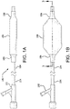
- Figure 1A is a side view of a catheter system 100 having a balloon 106 and a balloon cover 108 in accordance with an embodiment. Shown is a distal hub 102, a catheter shaft 104 and a balloon 106 that is shown deflated. The balloon cover 108 is shown surrounding a substantial portion of the balloon 106.
- Figure 1B is a side view of a balloon catheter system 100 having a hub 102, a catheter shaft 104 and a balloon 106 that is shown inflated. The balloon cover 108 is shown surrounding a substantial portion of the balloon 106. Also shown is a cross-sectional plane defined as "3 -3".
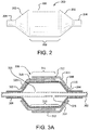
- FIG. 2 is a side view of a typical medical balloon 200. Shown is a balloon 200 having two opposed leg portions 204 that are integrally connected to shoulder/tapered portions 202.
- "working length" is defined as the length of the straight body section 206 of a balloon 200, which comprises the approximate length between the opposed shoulder/tapered portions202.
- the leg portions 204, shoulder/tapered portions 202 and the working length 208 define a balloon overall length.
- Figure 3A is a side-view cross-section taken along cross-sectional plane 3-3 of Figure 1B , showing the various portions of a balloon 304 and balloon cover 312 in accordance with an embodiment. Shown is a catheter shaft 302, inflation ports 325, and the balloon 304 coupled to the catheter shaft 302.
- the balloon cover 306 is positioned around balloon shoulder/tapered portions 308 and a working length 310 of the balloon 304.
- the balloon cover 306 comprises a first outer portion 312 that has a working length 311 approximating the balloon working length 310.
- the working length 311 of the first outer portion 312 of the balloon cover 306 is integrally connected to a tapered end 314 having an aperture 316 located at an apex of the tapered end 316.
- the balloon cover 306 further comprises a second inner portion 318 that has a working length 311 approximating the balloon working length 310.
- the working length 311 of the second inner portion 318 of the balloon cover 306 is integrally connected to a tapered end 320 having an aperture 322 located at an apex of the tapered end 320.
- the balloon cover 306 therefore has tapered ends (314, 320) of first outer and second inner portions (312, 318) that are located at opposite ends of the balloon cover 306.
- the working lengths 311 of the first outer and second inner portions (312, 318) overlap for a substantial portion of a balloon working length 310.
- substantially portion of the balloon working length means about over 50% to about 100% of the balloon working length 310.
- substantially portion of the balloon working length comprises over and/or about 60%, about 70%, about 80%, about 90%, about 95%, about 98% of the balloon working length 310.
- Shown in Figure 3B is a partial cross-sectional side view of a first outer portion 312 of a balloon cover 306, shown overlaying an inflated balloon 304.
- the additional layers shown in Figure 3A have been omitted for clarity.
- the aperture 316 is shown positioned about 20% "up along" the tapered shoulder portion 308 of the balloon 304.
- a position that is “zero %" up the tapered shoulder portion 308 is located at the junction of the balloon leg 321 and the balloon tapered shoulder 308.
- a position that is "100 % up the taper” is located at the junction of the balloon tapered shoulder 308 and the balloon working length 310, shown in Figure 3A .
- Figure 3C is an end view of a complete (non-cross-sectioned) balloon with a surrounding first cover portion 312. Shown is a cover aperture 316 positioned about 20% up the tapered shoulder portion 308 of the balloon 304. Also shown are inflated balloon diameter 324, balloon leg diameter 326 and first cover portion aperture diameter 328a. The position of the cover aperture 316 relative to the tapered shoulder portion 308 of the balloon 304 can be expressed as a ratio of cover aperture diameter 328a to the inflated balloon diameter 324. Similarly, the position of the cover aperture 3316 relative to the tapered shoulder portion 308 of the balloon 304 can be expressed as a ratio of cover aperture diameter 328a to the balloon leg diameter 326.
- Figures 3D and 3E are similar to previous Figures 3B and 3C .
- the cover aperture 316 is shown positioned about 75% "up along" the tapered shoulder portion 308 of the balloon 304.
- Figure 3E is an end view of a complete (non-cross-sectioned) balloon 304 with a surrounding first cover portion 312. Shown is a cover aperture 316 positioned about 75% up the tapered shoulder portion 308 of the balloon 304.
- inflated balloon diameter 324, balloon leg diameter 326 and first cover portion aperture diameter 328b are also shown. The position of the cover aperture 328b relative to the tapered shoulder portion 308 of the balloon 304 can be expressed as a ratio of cover aperture diameter 328b to the inflated balloon diameter 324.
- the position of the cover aperture 328b relative to the tapered shoulder portion 308 of the balloon 304 can be expressed as a ratio of cover aperture diameter 328b to the balloon leg diameter 326.
- Figures 3C and E are not drawn to scale, but are intended to illustrate a difference in the size of the cover aperture 304.
- the large cover aperture sizes are useful for many applications including for designing a balloon fail safe so that the balloon will fail only in the uncovered area such as the tapered shoulder portion 308 of the balloon 304 and/or for reducing pull through forces (see below) by reducing the amount of material in the tapered shoulder portion 308 and thus reducing profile in that area.
- Endoluminal balloons are typically blow molded from a uniform wall thickness tube. Once molded the tube is stretched and has varying wall thickness. The balloon is commonly thickest at the leg portions and becomes thinner up the tapered shoulder portion to the straight body section, which is the thinnest.
- Thickness is inverse to the stress on the balloon while under pressure.
- the thinnest wall of the blow molded balloon is under the greatest stress.
- the thick wall at the leg portions of the balloon introduces un-needed strength and extra mass. These thick leg portions reduce the minimum introducer size through which a balloon can be withdrawn.
- embodiment presented herein comprise a cover which provides additional strength to the balloon wall.
- the thinnest part of the balloon is the strongest part of the cover and vice versa.
- Balloon covers provided herein increase the rated burst pressure of a balloon with minimal addition to the withdrawal profile.
- Balloons and balloon covers can be fabricated from a variety of commonly known materials such as Amorphous Commodity Thermoplastics that include Polymethyl Methacrylate (PMMA or Acrylic), Polystyrene (PS), Acrylonitrile Butadiene Styrene (ABS), Polyvinyl Chloride (PVC), Modified Polyethylene Terephthalate Glycol (PETG), Cellulose Acetate Butyrate (CAB); Semi-Crystalline Commodity Plastics that include Polyethylene (PE), High Density Polyethylene (HDPE), Low Density Polyethylene (LDPE or LLDPE), Polypropylene (PP), Polymethylpentene (PMP); Amorphous Engineering Thermoplastics that include Polycarbonate (PC), Polyphenylene Oxide (PPO), Modified Polyphenylene Oxide (Mod PPO), Polyphenelyne Ether (PPE), Modified Polyphenelyne Ether (Mod PPE),Thermoplastic Polyurethane (TPU); Semi-Cry
- Balloon covers of embodiments provided herein can be fabricated by a variety of methods such as molding, vacuum/pressure forming, film-wrapping, film-layering, fiber winding or other methods known in the art.
- This method can comprise the following steps:
- balloon covers can incorporate additional balloon cover portions so that a balloon cover has more than two portions.
- a balloon cover in accordance with an embodiment can have two, three, four, five, six, seven, eight, nine, ten or more overlapping portions referred to as working lengths.
- Embodiments of balloon covers can also be formed to have tapered length portions and/or non-circular cross-sectional profiles.
- Balloon covers can also incorporate strengthening elements such as high strength fibers, braids or other elements to enhance the balloon cover strength or rigidity.
- Balloon covers can also incorporate surface treatments to provide drugs, therapeutic agents, lubricious coatings or radiopaque markings.
- a guidewire channel can also be provided between a balloon and a balloon cover resulting in an optional "rapid exchange" configuration.
- the balloon cover in accordance with examples presented herein is scalable to different size balloons.
- a 24 mm to 37 mm balloon with the cover of the invention may have a burst pressure of 9 Atm to 20 Atm.
- smaller diameter balloons e.g. a 5 mm diameter balloon can be converted to a high pressure balloon by the addition of the balloon cover in accordance with embodiments presented herein.
- an about 29 mm balloon with a rated burst pressure of 3 Atm is converted to a high pressure balloon with a burst pressure of about 11 Atm with the addition of the balloon cover in accordance with an embodiment.
- a 5 mm diameter balloon has a burst pressure of about 4,559625 MPa (45 Atm) with the addition of the balloon cover in accordance with an embodiment.
- a catheter balloon comprising an inflatable medical balloon having a balloon working length and an expanded and unexpanded diameter, and a balloon cover having a length and an expanded and unexpanded diameter, wherein the balloon cover comprises first and second portions, wherein the first and second portions each comprise a working length integrally connected to a tapered end having an aperture located at an apex of the tapered end, and wherein the tapered ends of the first and second portions are located at opposite ends of the balloon cover and the first and second working lengths of the first and second cover portions overlap for a substantial portion of the balloon working length.
- the medical balloon is a non-compliant balloon.
- the medical balloon is a compliant balloon.
- the balloon cover comprises a fibrillated material.
- the fibrillated material is ePTFE.
- fibrils in the ePTFE are oriented in a radial direction.
- the balloon cover is made from strips of ePTFE that are adhered to each other.
- the strips are laid in multiple angular orientations on the working length and the tapered ends of the balloon cover.
- the balloon cover is adhered to the medical balloon.
- working lengths that overlap for a substantial portion of the balloon working length also cover a portion of a balloon shoulder.
- the expanded diameter of the balloon cover is smaller than the expanded diameter of the medical balloon.
- Another embodiment comprises a balloon cover comprising a length, an unexpanded and expanded diameter, and first and second portions, wherein the first and second portions each comprise a working length integrally connected to a tapered end having an aperture located at an apex of the tapered end, and wherein the tapered ends of the first and second portions are located at opposite ends of the balloon cover and the first and second working lengths overlap for a substantial portion of the length of the balloon cover.
- Figures 12A through 12E show partial cross-sectional side views of first and second balloon cover portions (1212, 1218) along with various intermediate cover portions (1230, 1234, 1236, 1238, 1240). Shown in Figure 12A are first and second balloon cover portions (1212, 1218) and an intermediate cover portion 1230. The first and second balloon cover portions (1212, 1218) are shown closely abutted defining a small gap 1232.
- Figure 12B is similar to previous Figure 12A , showing first and second balloon cover portions (1212, 1218) and an intermediate cover portion 1234. The first and second balloon cover portions (1212, 1218) are shown spaced apart with a gap 1235, with the intermediate cover portion 1234 bridging the gap 1235, and overlapped by a portion of the first and second balloon cover portions (1212, 1218).
- Figure 12C shows first and second balloon cover portions (1212, 1218) and an intermediate cover portion 1236 having a stepped diameter that is smaller than the diameters of the first and second balloon cover portions.
- the first and second balloon cover portions (1212, 1218) are shown spaced apart with a gap 1235, with the intermediate cover portion 1234 bridging the gap 1235, and overlapped by a portion of the first and second balloon cover portions (1212, 1218).
- Figure 12D shows first and second balloon cover portions (1212, 1218) and an intermediate cover portion 1238 having a stepped diameter that is larger than the diameters of the first and second balloon cover portions.
- the first and second balloon cover portions (1212, 1218) are shown spaced apart with a gap 1235, with the intermediate cover portion 1236 bridging the gap 1235, and overlapped by a portion of the first and second balloon cover portions (1212, 1218).
- Figure 12E shows first and second balloon cover portions (1212, 1218) and an intermediate cover portion 1240 having a stepped diameter that is larger than the diameters of the first and second balloon cover portions.
- the larger stepped diameter 1240 incorporates a groove 1242 along the circumference of the stepped diameter.
- the first and second balloon cover portions (1212, 1218) are shown spaced apart with a gap 1235, with the intermediate cover portion 1240 bridging the gap 1235, and overlapped by a portion of the first and second balloon cover portions (1212, 1218).
- Balloon covers provided herein can incorporate one, two, three, four, five or more additional intermediate cover portions.
- the intermediate cover portions can have similar or dissimilar shapes or profiles and can be configured for a specific application.
- a stepped intermediate cover portion can be configured to expand and anchor a heart valve stent.
- a balloon cover comprises a length, first and second portions, an unexpanded and expanded diameter, and an intermediate section comprising first and second ends, wherein the first and second portions each comprises a working length integrally connected to a tapered end having an aperture located at an apex of the tapered end, wherein the tapered ends of the first and second portions are located at opposite ends of the balloon cover and wherein the first end of the intermediate section overlaps with the working length of the first portion and the second end of the intermediate section overlaps with the working length of the second portion.
- a balloon cover comprises a length, first and second portions, an unexpanded and expanded diameter, and an intermediate section comprising first and second ends, wherein the first and second portions each comprises a working length integrally connected to a tapered end having an aperture located at an apex of the tapered end, wherein the tapered ends of the first and second portions are located at opposite ends of the balloon cover and wherein the first end of the intermediate section overlaps with the working length of the first portion and the second end of the intermediate section overlaps with the working length of the second portion.
- the intermediate section when the balloon cover is in its expanded diameter, confers to the balloon cover a shape selected from the group consisting of an hourglass, triangular, square, rectangular, oval or other polygon.
- the intermediate section is made from a different material than the first and second portions.
- the intermediate section is made from ePTFE.
- first and second balloon cover portions (1300, 1310) having working lengths (1302, 1312), opposing apertures (1306, 1316) and essentially spherical tapered shoulder portions 1324.
- the tapered shoulder portions 1324 can be configured to match the inflated profile of a specific balloon.
- a balloon cover of the present invention was fabricated according to the previously described steps 1) through 20), with the following additional details:
- the balloon cover was undersized (relative to the balloon inflated diameter) by about 5%, allowing the balloon cover to absorb the load imparted to the cover by the inflated balloon.
- the balloon with attached balloon covers from EXAMPLE 1 was subjected to a pull through test.
- the pull through test was designed to measure the force required to pull a deflated balloon through a series of gage holes.
- the test was designed to emulate the force required to retract a deflated balloon back into an introducer sheath.
- a vertical universal mechanical testing system (Instron®, Model 5564, Norwood, MA, USA) with a 10.2kg tension load cell was configured to measure pull through forces.
- a water bath was aligned to the testing system and heated to about 37°C.
- a balloon catheter with balloon covers (from EXAMPLE 1) was provided. A distal portion of the balloon catheter shaft was clamped to the load cell head. The gage with a series of varying diameter pull through holes was "split open" to allow a proximal portion of the catheter shaft to be inserted into a first, large diameter hole (22F or about 0.29" with a chamfered/broken edge lead in). The gage halves were then aligned and clamped together, surrounding the proximal portion of the catheter shaft. The balloon was then inflated to about 2 ATM and then deflated with a vacuum. The vacuum was maintained with a stopcock located on the proximal end of the catheter. The deflated balloon was then pulled up through the gage hole at rate of about 254 mm/minute (10"/minute) while the instant pull force was recorded.
- the gage was then split open and the catheter shaft was positioned into the next smaller gage hole.
- the gage was reassembled, the balloon was re-inflated to about 2,0265 Bar (2 ATM) and deflated as previously described.
- the catheter/balloon was then pulled through the gage hole while the instant pull force was recorded.
- the test sequence was repeated using progressively smaller gage pull through holes. The test sequence was terminated if the balloon ruptured/leaked during inflation, or if the pull through force exceeded a pre-determined limit.
- the pull through hole diameters for a typical 29mm underlying balloon with balloon covers according to EXAMPLE 1, ranged from 22F (about 0.29") to 11F (about 0.145").
- the balloon with attached balloon covers from EXAMPLE 1 was subjected to a balloon compliance, inflation/burst test.
- the balloon compliance, inflation/burst test was designed to measure the balloon diameter vs. internal pressure along with determining the internal balloon pressure required to rupture/burst the balloon and attached covers from EXAMPLE 1.
- a balloon compliance/burst test system was provided (Interface Associates, Website Niguel, CA, USA, Model PT3070).
- the test system had a water bath heated to about 37°C, a pressurized water feed/pressure measurement system and a laser micrometer to measure the outer diameter of the expanded balloon and balloon covers.
- the balloon with attached balloon covers was purged of air by a series of vacuum air withdrawals followed by water inflations. The purging was repeated until no more air could be withdrawn from the balloon catheter. After air purging, the catheter was subjected to the compliance/burst test.
- Balloons with attached covers from EXAMPLE 1 were subjected to the pull through test (EXAMPLE 2) and to the balloon compliance, inflation/burst test (EXAMPLE 3). Additionally, underlying or'uncovered balloons were subjected to the pull through and compliance/burst test to generate comparative data.
- the test results are displayed in Figures 11A and 11B .
Landscapes
- Health & Medical Sciences (AREA)
- Life Sciences & Earth Sciences (AREA)
- Heart & Thoracic Surgery (AREA)
- Biomedical Technology (AREA)
- Animal Behavior & Ethology (AREA)
- Pulmonology (AREA)
- Engineering & Computer Science (AREA)
- Anesthesiology (AREA)
- Child & Adolescent Psychology (AREA)
- Hematology (AREA)
- Biophysics (AREA)
- General Health & Medical Sciences (AREA)
- Public Health (AREA)
- Veterinary Medicine (AREA)
- Vascular Medicine (AREA)
- Media Introduction/Drainage Providing Device (AREA)
- Materials For Medical Uses (AREA)
Description
- This disclosure relates generally to a catheter balloon.
- Balloon angioplasty is a widely used procedure for expanding constricted body passageways, such as arteries and other blood vessels. In an angioplasty procedure, an uninflated angioplasty balloon attached to a catheter is delivered to a constricted region of a body passageway. Once the balloon is in position at the constricted region, fluid is injected through a lumen of the catheter and into the balloon. The balloon consequently inflates and exerts pressure against the constricted region to expand the passageway. After use, the balloon is collapsed, and the catheter is withdrawn.
- Balloons have a number of critical design parameters. One is rated burst pressure, which is the statistically-determined maximum pressure to which a balloon may be inflated without rupturing. In order to expand hard, calcified lesions, it is desirable that the balloon have a rated burst pressure of at least 15 bar. It is also desirable that the balloon have a low wall thickness to minimize the profile of the delivery system. For a given balloon material, however, there is a trade-off between burst pressure and wall thickness, in that the burst pressure generally decreases when the wall thickness is reduced.
- Accordingly, there is a need for a means of increasing the strength of a balloon to attain a higher rated burst pressure while maintaining a low delivery profile.
-
WO2009149108 (A1 ) discloses inflatable medical devices and methods for making the same. The inflatable medical devices can be medical balloons and the balloons can be configured to have a through-lumen or no through-lumen and a wide variety of geometries. The device can have a high-strength, non-compliant, fiber-reinforced, multi-layered wall. - An embodiment comprises a catheter balloon having a working length and an expanded and an unexpanded diameter. At least partially surrounding the balloon is a balloon cover having a length and an expanded and unexpanded diameter. Wherein the balloon cover comprises first and second portions, wherein the first and second portions each comprise a working length integrally connected to a tapered end having an aperture located at an apex of the tapered end and the tapered ends of the first and second portions are located at opposite ends of the balloon cover, and the first and second working lengths of the first and second cover portions overlap at least a substantial portion of the balloon working length.
- Another embodiment comprises a balloon cover having a length, an unexpanded and expanded diameter, and first and second portions, wherein the first and second portions each comprise a working length integrally connected to a tapered end having an aperture located at an apex of the tapered end, and wherein the tapered ends of the first and second portions are located at opposite ends of the balloon cover, and the first and second working lengths substantially overlap.
- Another embodiment comprises a balloon cover having a length, first and second portions, an unexpanded and expanded diameter, and an intermediate section comprising first and second ends, wherein the first and second portions each comprise a working length integrally connected to a tapered end having an aperture located at an apex of the tapered end, wherein the tapered ends of the first and second portions are located at opposite ends of the balloon cover and wherein the first end of the intermediate section overlaps with the working length of the first portion and the second end of the intermediate section overlaps with the working length of the second portion.
- The accompanying drawings are included to provide a further understanding of the invention and are incorporated in and constitute a part of this specification, illustrate embodiments of the invention, and together with the description serve to explain the principles of the invention.
-
Figures 1A and 1B are top plane views of a balloon catheter and balloon cover in accordance with an embodiment; -
Figure 2 is a schematic drawing of a typical medical balloon; -
Figure 3A is a cross-sectional view of a catheter shaft, a balloon and a balloon cover in accordance with an embodiment; -
Figures 3B through 3E are partial cross-sectional and side views of balloon covers having different aperture locations relative to the balloon tapered portion, in accordance with embodiments; -
Figure 4 is a perspective view of a mandrel used to form balloon cover portions ; -
Figure 5 is a perspective view of a mandrel used to form balloon cover portions, further showing a manufacturing aid; -
Figures 6A through 6E are front, right, rear, left and top plane views of a mandrel and a film lay-up ; -
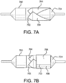
Figures 7A and 7B are top plane views of a mandrel with film lay-up straps and an additional radial film layer ; -
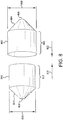
Figure 8 is a perspective view of first and second balloon cover portions in accordance with an embodiment; -
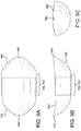
Figures 9A through 9C are top, front and right side plane views of a folded balloon cover in accordance with an embodiment; -
Figures 10A through 10C are perspective, front and right plane views of a folded balloon cover, depicting a bonding process ; -
Figure 11A and 11B are tabulations of burst and pull through test results for covered and uncovered balloons in accordance with embodiments; -
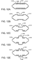
Figures 12A through 12E are cross-sectional side views of balloon covers in accordance with embodiments incorporating an additional intermediate cover portion; and -
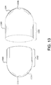
Figure 13 is a perspective view of first and second balloon cover portions in accordance with an embodiment having essentially spherical tapered portions. - It will be apparent to those skilled in the art that various modifications and variations can be made in the present invention without departing from the scope of the invention. Thus, it is intended that the present invention cover the modifications and variations of the invention provided they come within the scope of the appended claims and their equivalents.
- Described herein are examples of methods of making a reinforced medical balloon. The methods provide a high-strength, thin-walled medical balloon that can withstand high inflation pressures without rupturing. As used herein, the term "proximal" relates to a direction that is "closest to the heart", while "distal" relates to a direction that is "furthest from the heart".
-
Figure 1A is a side view of acatheter system 100 having aballoon 106 and aballoon cover 108 in accordance with an embodiment. Shown is adistal hub 102, acatheter shaft 104 and aballoon 106 that is shown deflated. Theballoon cover 108 is shown surrounding a substantial portion of theballoon 106.Figure 1B is a side view of aballoon catheter system 100 having ahub 102, acatheter shaft 104 and aballoon 106 that is shown inflated. Theballoon cover 108 is shown surrounding a substantial portion of theballoon 106. Also shown is a cross-sectional plane defined as "3 -3". -
Figure 2 is a side view of a typicalmedical balloon 200. Shown is aballoon 200 having twoopposed leg portions 204 that are integrally connected to shoulder/taperedportions 202. For the purposes of this disclosure, "working length" is defined as the length of thestraight body section 206 of aballoon 200, which comprises the approximate length between the opposed shoulder/tapered portions202. Theleg portions 204, shoulder/tapered portions 202 and the workinglength 208 define a balloon overall length. -
Figure 3A is a side-view cross-section taken along cross-sectional plane 3-3 ofFigure 1B , showing the various portions of aballoon 304 andballoon cover 312 in accordance with an embodiment. Shown is acatheter shaft 302,inflation ports 325, and theballoon 304 coupled to thecatheter shaft 302. Theballoon cover 306 is positioned around balloon shoulder/tapered portions 308 and a workinglength 310 of theballoon 304. Theballoon cover 306 comprises a firstouter portion 312 that has a workinglength 311 approximating theballoon working length 310. The workinglength 311 of the firstouter portion 312 of theballoon cover 306 is integrally connected to atapered end 314 having anaperture 316 located at an apex of thetapered end 316. Theballoon cover 306 further comprises a secondinner portion 318 that has a workinglength 311 approximating theballoon working length 310. The workinglength 311 of the secondinner portion 318 of theballoon cover 306 is integrally connected to atapered end 320 having anaperture 322 located at an apex of thetapered end 320. - The
balloon cover 306 therefore has tapered ends (314, 320) of first outer and second inner portions (312, 318) that are located at opposite ends of theballoon cover 306. In addition, theworking lengths 311 of the first outer and second inner portions (312, 318) overlap for a substantial portion of aballoon working length 310. For the purposes of this disclosure, "substantial portion of the balloon working length" means about over 50% to about 100% of theballoon working length 310. In specific embodiments, "substantial portion of the balloon working length" comprises over and/or about 60%, about 70%, about 80%, about 90%, about 95%, about 98% of theballoon working length 310. - Shown in
Figure 3B is a partial cross-sectional side view of a firstouter portion 312 of aballoon cover 306, shown overlaying aninflated balloon 304. The additional layers shown inFigure 3A have been omitted for clarity. Theaperture 316 is shown positioned about 20% "up along" the taperedshoulder portion 308 of theballoon 304. As indicated, a position that is "zero %" up the taperedshoulder portion 308 is located at the junction of theballoon leg 321 and the balloon taperedshoulder 308. A position that is "100 % up the taper" is located at the junction of the balloon taperedshoulder 308 and theballoon working length 310, shown inFigure 3A .Figure 3C is an end view of a complete (non-cross-sectioned) balloon with a surroundingfirst cover portion 312. Shown is acover aperture 316 positioned about 20% up the taperedshoulder portion 308 of theballoon 304. Also shown are inflatedballoon diameter 324,balloon leg diameter 326 and first coverportion aperture diameter 328a. The position of thecover aperture 316 relative to the taperedshoulder portion 308 of theballoon 304 can be expressed as a ratio ofcover aperture diameter 328a to theinflated balloon diameter 324. Similarly, the position of the cover aperture 3316 relative to the taperedshoulder portion 308 of theballoon 304 can be expressed as a ratio ofcover aperture diameter 328a to theballoon leg diameter 326. -
Figures 3D and 3E are similar to previousFigures 3B and 3C . As shown inFigure 3D , thecover aperture 316 is shown positioned about 75% "up along" the taperedshoulder portion 308 of theballoon 304.Figure 3E is an end view of a complete (non-cross-sectioned)balloon 304 with a surroundingfirst cover portion 312. Shown is acover aperture 316 positioned about 75% up the taperedshoulder portion 308 of theballoon 304. Also shown are inflatedballoon diameter 324,balloon leg diameter 326 and first coverportion aperture diameter 328b. The position of thecover aperture 328b relative to the taperedshoulder portion 308 of theballoon 304 can be expressed as a ratio ofcover aperture diameter 328b to theinflated balloon diameter 324. Similarly, the position of thecover aperture 328b relative to the taperedshoulder portion 308 of theballoon 304 can be expressed as a ratio ofcover aperture diameter 328b to theballoon leg diameter 326. Note thatFigures 3C and E are not drawn to scale, but are intended to illustrate a difference in the size of thecover aperture 304. - The large cover aperture sizes are useful for many applications including for designing a balloon fail safe so that the balloon will fail only in the uncovered area such as the
tapered shoulder portion 308 of theballoon 304 and/or for reducing pull through forces (see below) by reducing the amount of material in the taperedshoulder portion 308 and thus reducing profile in that area. - Endoluminal balloons are typically blow molded from a uniform wall thickness tube. Once molded the tube is stretched and has varying wall thickness. The balloon is commonly thickest at the leg portions and becomes thinner up the tapered shoulder portion to the straight body section, which is the thinnest.
- Thickness is inverse to the stress on the balloon while under pressure. The thinnest wall of the blow molded balloon is under the greatest stress. The thick wall at the leg portions of the balloon introduces un-needed strength and extra mass. These thick leg portions reduce the minimum introducer size through which a balloon can be withdrawn.
- Thus, embodiment presented herein comprise a cover which provides additional strength to the balloon wall. In particular, the thinnest part of the balloon is the strongest part of the cover and vice versa. Balloon covers provided herein increase the rated burst pressure of a balloon with minimal addition to the withdrawal profile.
- Balloons and balloon covers can be fabricated from a variety of commonly known materials such as Amorphous Commodity Thermoplastics that include Polymethyl Methacrylate (PMMA or Acrylic), Polystyrene (PS), Acrylonitrile Butadiene Styrene (ABS), Polyvinyl Chloride (PVC), Modified Polyethylene Terephthalate Glycol (PETG), Cellulose Acetate Butyrate (CAB); Semi-Crystalline Commodity Plastics that include Polyethylene (PE), High Density Polyethylene (HDPE), Low Density Polyethylene (LDPE or LLDPE), Polypropylene (PP), Polymethylpentene (PMP); Amorphous Engineering Thermoplastics that include Polycarbonate (PC), Polyphenylene Oxide (PPO), Modified Polyphenylene Oxide (Mod PPO), Polyphenelyne Ether (PPE), Modified Polyphenelyne Ether (Mod PPE),Thermoplastic Polyurethane (TPU); Semi-Crystalline Engineering Thermoplastics that include Polyamide (PA or Nylon), Polyoxymethylene (POM or Acetal), Polyethylene Terephthalate (PET, Thermoplastic Polyester), Polybutylene Terephthalate (PBT, Thermoplastic Polyester), Ultra High Molecular Weight Polyethylene (UHMW-PE); High Performance Thermoplastics that include Polyimide (PI, Imidized Plastic), Polyamide Imide (PAI, Imidized Plastic), Polybenzimidazole (PBI, Imidized Plastic); Amorphous High Performance Thermoplastics that include Polysulfone (PSU), Polyetherimide (PEI), Polyether Sulfone (PES), Polyaryl Sulfone (PAS); Semi-Crystalline High Performance Thermoplastics that include Polyphenylene Sulfide (PPS), Polyetheretherketone (PEEK); and Semi-Crystalline High Performance Thermoplastics, Fluoropolymers that include Fluorinated Ethylene Propylene (FEP), Ethylene Chlorotrifluroethylene (ECTFE), Ethylene, Ethylene Tetrafluoroethylene (ETFE), Polychlortrifluoroethylene (PCTFE), Polytetrafluoroethylene (PTFE), Polyvinylidene Fluoride (PVDF), Perfluoroalkoxy (PFA). Other commonly known medical grade materials include elastomeric organosilicon polymers, polyether block amide or thermoplastic copolyether (PEBAX).
- Balloon covers of embodiments provided herein can be fabricated by a variety of methods such as molding, vacuum/pressure forming, film-wrapping, film-layering, fiber winding or other methods known in the art.
- The following describes one example of a method, utilizing thin, polymeric film lay-ups that can be used to fabricate various balloon covers according to the present invention. This method can comprise the following steps:
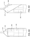
- 1) A stepped metallic, film lay-up mandrel can be fabricated according to
Figure 4 . Shown is ametallic mandrel 400 having a firstcylindrical portion 402. The firstcylindrical portion 402 has adiameter 404 and alength 406. Similarly, themetallic mandrel 400 has a secondcylindrical portion 408. The secondcylindrical portion 408 has adiameter 410 and alength 412. The first and secondcylindrical portions diameters 422. The lengths (406, 412), diameters (404, 410) and shoulder (414, 416) dimensions can be tailored to accommodate the dimensions of a subsequent underlying balloon. Lengths (406, 412) can range from about 1mm to more than 100mm, diameters (404, 410) can range from about 1mm to more than 100mm and shoulder angles can range from about 10° to about 90°. In one embodiment, the cover diameter is undersized by about at least 5% relative to the balloon diameter. Undersizing the balloon cover by at least 5% allows the balloon cover to bear the radial load, thus not allowing the balloon to fail, at least in the covered region of the balloon.
Themandrel 400 can be used to form two cover cup portions having overlapping working lengths. For the working lengths to overlap, a first cup is fabricated to have a working length inner diameter that is slightly larger than the working length outer diameter of the second cup. The difference between the working length diameters is dictated by the different diameters of the firstcylindrical portion 402 and the secondcylindrical portion 408. Forexample diameter 404 can be about 0.3048 mm (0.012") thandiameter 410, accommodating covers with a 0.1524 mm (0.006 ") wall thickness. - 2) One of the shafts (418, 420) can be mounted onto a rotatable collet to hold the mandrel and allow rotation of the mandrel during subsequent processing steps. As shown in
Figure 5 , a manufacturing aid, in the form of afilm 502 coated with a thermoplastic adhesive, can be added to the center portion of themandrel 500. For example, two to five circumferential wraps can be applied. The layers can be secured by reflowing the thermoplastic adhesive by the application of heat, such as by a soldering iron or other heating means. The width of the film and the location on the mandrel, can be selected to accommodate the dimensions of desired cover portions. A suitable film can comprise expanded polytetrafluoroethylene (ePTFE) imbibed or coated with a thermoplastic fluoroelastomer or other combinations of polymeric films and thermoplastics. - 3) As described in
Figures 6A through 6E , a series of film layers or straps can be applied onto the first cylindrical portion (larger diameter relative to the second cylindrical portion) and onto the integrally connected tapered shoulder portion of the mandrel. Shown inFigure 6A is a front plane view of amandrel 600 with a strap of athin polymeric film 604 positioned over atapered shoulder portion 614. Shown inFigure 6B is a right side plane view (ofFigure 6A ) of amandrel 600 with a strap of athin polymeric film 604 positioned over atapered shoulder portion 614. As shown, thefilm strap 604 is closely abutted against the base of theintegral shaft 618. Similarly,Figure 6C is a rear side plane view (ofFigure 6A ) of amandrel 600 with a strap of athin polymeric film 604 positioned over atapered shoulder portion 614.Figure 6D is a left side plane view (ofFigure 6A ) of amandrel 600 with a strap of athin polymeric film 604 positioned over atapered shoulder portion 614. Note that the width and size of the straps can vary depending on the application. - 4) The portions of the
film strap 604 overlying the film/thermoplastic manufacturing aid 602 can be smoothed out and heat tacked to themanufacturing aid 602, resulting in one film strap formed onto themandrel 600. - 5)
Figure 6E is a top plane view (ofFigure 6A ) showing thefilm 604 closely abutted against theintegral shaft 618. For reference, the film shown is oriented (relative to the mandrel 600) at a "zero degree" position. Two additional film straps can be added in a "clocked" fashion whereby the point where the film strap abuts theintegral shaft 618 is oriented about 120° relative to the previous film strap. The two additional film straps can be heat tacked to themanufacturing aid 602, resulting in three film straps formed onto themandrel 600. - 6) The polymeric film used as a film strap can comprise an expanded polytetrafluoroethylene (ePTFE) film, coated on one side with a thermoplastic (or thermoset) adhesive. The three film straps of
Figures 6A through 6E can have the adhesive side oriented out and away from the mandrel.
ePTFE may be made as taught byU.S. Pat. Nos. 3,953,566 and4,187,390 . In another embodiment, the ePTFE is impregnated with a thermoplastic (or thermoset) adhesive, silicone adhesive, silicone elastomer, silicone dispersion, polyurethane or another suitable elastomeric material. Impregnation involves at least partially filling the pores of the porous ePTFE.U.S. Pat. No. 5,519,172 teaches in detail the impregnation of porous ePTFE with elastomers, such as the one taught inU.S. Pat. 7,462,675 . In one example, the film comprises an elastomer so that when formed into a balloon cover in accordance with the present invention, the cover will expand and contract, thus also contracting and/or refolding the balloon. - 7) A circumferentially wrapped film layer can be added to the wrapped mandrel from step 5). Shown in
Figure 7A is amandrel 700 having a wrappedfilm manufacturing aid 702 and three polymeric film straps 704 wrapped according to step 5). As shown inFigure 7B , afilm layer 706 can be circumferentially wrapped about the first cylindrical portion (Figure 4 , 402). The circumferentially wrappedfilm layer 706 can have an end-to-end (708, 710) overlap as shown. The polymeric film used as acircumferential wrap 706 can comprise an ePTFE film, coated on one side with a thermoplastic (or thermoset) adhesive. Thecircumferential wrap 706 can have the adhesive side oriented out and away from the mandrel. The overlapping ends of the film can be heat tacked and bonded together. - 8) Three additional film straps can be added to the first cylindrical portion (
Figure 4 , 402) according to the method of step 5). The first additional film strap can be added in "clocked" fashion whereby the point where the film strap abuts the integral shaft 618 (Figure 6 ) is oriented about 60° relative to the previous film strap. The second and third additional film straps can then be added in a "clocked" fashion whereby the point where the film strap abuts the integral shaft 618 (Figure 6 ) is oriented about 120° relative to the previous film strap. - 9) The portions of the film straps overlying the film/thermoplastic manufacturing aid 602 (
Figure 6 ) can be smoothed out and heat tacked to the manufacturing aid. - 10) The polymeric film used as a film strap can comprise an ePTFE film, coated on one side with a thermoplastic (or thermoset) adhesive. The three additional film straps of step 8) can have the adhesive side oriented inward and towards the mandrel.
- 11) A circumferentially wrapped film layer can be added to the wrapped mandrel from step 8), similar to that of step 7). The polymeric film used as a circumferential wrap can comprise an ePTFE film, coated on one side with a thermoplastic (or thermoset) adhesive. The circumferential wrap can have the adhesive side oriented inward and towards the mandrel.
- 12) Using a process as similar to that described in
Figures 6A through 6E , a series of film layers or straps can be applied onto the second cylindrical portion (smaller diameter relative to the first cylindrical portion) and onto the integrally connected tapered shoulder portion of the mandrel. - 13) Six film straps can be applied according to the process of steps 3-6, 8-9). The adhesive side of the film straps can be oriented out and away from the mandrel.
- 14) Two layers of a circumferentially wrapped film can be added to the wrapped mandrel from step 13). The circumferentially wrapped film can be applied according to the process of step 7) and can have the adhesive side of the film straps oriented out and away from the mandrel.
- 15) The mandrel with film wrapped first and second cylindrical portions and integrally connected tapered shoulder portions can then be heat treated in an air convection (e.g. in an over set of 250° C for about 30 minutes). The heat treatment reflows the thermoplastic adhesive and bonds the various film layers together. The mandrel and films can then be ambient, forced air cooled for about 30 minutes.
- 16) The bonded films on the first and second cylindrical portions and integrally connected tapered shoulder portions can then be circumferentially cut and removed from the mandrel. The location of the circumferential cut can determine the desired working lengths of the first and second cylindrical cup portions. Shown in
Figure 8 is a first, large diameter outerballoon cover portion 800 having a workinglength 802 integrally connected to a tapered end orshoulder portion 804. The tapered end orshoulder portion 804 has anaperture 806 located at an apex of thetapered end 804. Also shown inFigure 8 is a second, small diameter outerballoon cover portion 810 having a workinglength 812 integrally connected to a tapered end orshoulder portion 814. The tapered end orshoulder portion 814 has anaperture 816 located at an apex of thetapered end 814. - 17) As further shown in
Figure 8 , the second, small diameter outerballoon cover portion 810 can be inserted into the first, large diameter outerballoon cover portion 800 by translating the second and first cylindrical cup portions as indicated by direction arrows (820, 822), so that the working lengths (812, 802) are substantially overlapped. For the purposes of this embodiment "substantially overlapped" means that about over 50% to about 100% of the working lengths (812, 802) of the first and second cylindrical cup portions, which correspond to thecover working lengths 311 shown inFigure 3A , overlap. In specific embodiments, "substantially overlapped" comprises about 60%, about 70%, about 80%, about 90%, about 95%, about 98% of the cover working length. - 18) In preparation for bonding the working lengths (802, 812) together, the first and second cover portions (800, 810) are flattened-out to form a cup-shaped assembly as generally depicted in
Figures 9A through 9C. Figure 9A is a top plane view of flattened first 900 and second 910 cover portions. As shown, the working lengths (902, 912) are substantially overlapped. Also shown are apertures (906, 916) located at the apexes of the tapered ends of the first balloon and second balloon cover portions.Figure 9B is a front plane view of the cup-shaped assembly shown inFigure 9A , whileFigure 9C is a right side plane view of the cup-shaped assembly shown inFigure 9A . - 19)
Figures 10A through 10C describe a process used to bond the first and second cover portion working lengths together. Shown inFigure 10A is ametallic ring 1000 having a length (1002, 1012) that approximates the first and second cover portion working lengths (1002, 1012). As shown inFigure 10B and 10C , thering 1000 can be inserted into the cup-shaped assembly ofFigures 9A through 9C . As shown inFigure 10C , thering 1000 has adiameter 1010 dimensioned to mate into the cup-shaped assembly ofFigures 9A through 9C . A layer of high temperature polymeric film, such as Kapton® can then be wrapped around the ring and cup-shaped assembly. A high temperature fiber can be wrapped about the high temperature polymeric film, the ring and cup-shaped assembly. When heated, the high temperature fiber can shrink and contract about the high temperature polymeric film and the ring and cup-shaped assembly, and therefore apply pressure onto the overlapped working lengths of the balloon cover portions. After securing the high temperature fiber, the components can be heated in an air convection oven to about 250°C for about 30 minutes. The pressure applied by the contracting high temperature fiber causes the thermoplastic layers within the overlapped working lengths to reflow and form a bond between the layers. - 20) The components from step 20) can then be ambient forced air cooled for about 30 minutes. The high temperature fiber, high temperature film and the metallic ring can be removed and the two bonded balloon cover portions can be expanded. A compacted balloon, mounted onto a catheter, can be inserted into the expanded balloon cover portions, thereby forming a covered balloon as previously described in
Figure 3 . The balloon can be inflated to conform to the balloon cover and then be partially deflated. While the balloon is partially deflated, an adhesive can be injected into the balloon cover apertures (906, 916 ofFigure 9A ) to bond the opposing ends of the balloon cover to the underlying balloon. The adhesive can be cured, forming a catheter system having a proximal balloon and a balloon cover according to the present invention, as depicted inFigures 1A and 1B . In one embodiment, the balloon cover does not cover theleg portions 204, as shown inFigure 2 , of a balloon. In another embodiment, the balloon cover is not attached to a catheter, or any other structure that a balloon is mounted. In another embodiment, the balloon cover does not have leg portions (in accordance withFigure 2 ). - Various alternative examples of the ballon cover can be fabricated. For example, balloon covers can incorporate additional balloon cover portions so that a balloon cover has more than two portions. A balloon cover in accordance with an embodiment can have two, three, four, five, six, seven, eight, nine, ten or more overlapping portions referred to as working lengths. Embodiments of balloon covers can also be formed to have tapered length portions and/or non-circular cross-sectional profiles. Balloon covers can also incorporate strengthening elements such as high strength fibers, braids or other elements to enhance the balloon cover strength or rigidity. Balloon covers can also incorporate surface treatments to provide drugs, therapeutic agents, lubricious coatings or radiopaque markings. A guidewire channel can also be provided between a balloon and a balloon cover resulting in an optional "rapid exchange" configuration.
- The balloon cover in accordance with examples presented herein is scalable to different size balloons. Thus, a 24 mm to 37 mm balloon with the cover of the invention may have a burst pressure of 9 Atm to 20 Atm. Similarly smaller diameter balloons, e.g. a 5 mm diameter balloon can be converted to a high pressure balloon by the addition of the balloon cover in accordance with embodiments presented herein. In one example, an about 29 mm balloon with a rated burst pressure of 3 Atm is converted to a high pressure balloon with a burst pressure of about 11 Atm with the addition of the balloon cover in accordance with an embodiment. In another example, a 5 mm diameter balloon has a burst pressure of about 4,559625 MPa (45 Atm) with the addition of the balloon cover in accordance with an embodiment.
- Thus one embodiment comprises a catheter balloon comprising an inflatable medical balloon having a balloon working length and an expanded and unexpanded diameter, and a balloon cover having a length and an expanded and unexpanded diameter, wherein the balloon cover comprises first and second portions, wherein the first and second portions each comprise a working length integrally connected to a tapered end having an aperture located at an apex of the tapered end, and wherein the tapered ends of the first and second portions are located at opposite ends of the balloon cover and the first and second working lengths of the first and second cover portions overlap for a substantial portion of the balloon working length. In another embodiment, the medical balloon is a non-compliant balloon. In another embodiment, the medical balloon is a compliant balloon. In another embodiment, the balloon cover comprises a fibrillated material. In another embodiment, the fibrillated material is ePTFE. In another embodiment, fibrils in the ePTFE are oriented in a radial direction. In another embodiment, wherein the balloon cover is made from strips of ePTFE that are adhered to each other. In another embodiment, the strips are laid in multiple angular orientations on the working length and the tapered ends of the balloon cover. In another embodiment, the balloon cover is adhered to the medical balloon. In another embodiment, working lengths that overlap for a substantial portion of the balloon working length also cover a portion of a balloon shoulder. In another embodiment, the expanded diameter of the balloon cover is smaller than the expanded diameter of the medical balloon.
- Another embodiment comprises a balloon cover comprising a length, an unexpanded and expanded diameter, and first and second portions, wherein the first and second portions each comprise a working length integrally connected to a tapered end having an aperture located at an apex of the tapered end, and wherein the tapered ends of the first and second portions are located at opposite ends of the balloon cover and the first and second working lengths overlap for a substantial portion of the length of the balloon cover.
- In another embodiment,
Figures 12A through 12E show partial cross-sectional side views of first and second balloon cover portions (1212, 1218) along with various intermediate cover portions (1230, 1234, 1236, 1238, 1240). Shown inFigure 12A are first and second balloon cover portions (1212, 1218) and anintermediate cover portion 1230. The first and second balloon cover portions (1212, 1218) are shown closely abutted defining asmall gap 1232.Figure 12B is similar to previousFigure 12A , showing first and second balloon cover portions (1212, 1218) and anintermediate cover portion 1234. The first and second balloon cover portions (1212, 1218) are shown spaced apart with agap 1235, with theintermediate cover portion 1234 bridging thegap 1235, and overlapped by a portion of the first and second balloon cover portions (1212, 1218). -
Figure 12C shows first and second balloon cover portions (1212, 1218) and anintermediate cover portion 1236 having a stepped diameter that is smaller than the diameters of the first and second balloon cover portions. The first and second balloon cover portions (1212, 1218) are shown spaced apart with agap 1235, with theintermediate cover portion 1234 bridging thegap 1235, and overlapped by a portion of the first and second balloon cover portions (1212, 1218). -
Figure 12D shows first and second balloon cover portions (1212, 1218) and anintermediate cover portion 1238 having a stepped diameter that is larger than the diameters of the first and second balloon cover portions. The first and second balloon cover portions (1212, 1218) are shown spaced apart with agap 1235, with theintermediate cover portion 1236 bridging thegap 1235, and overlapped by a portion of the first and second balloon cover portions (1212, 1218). -
Figure 12E shows first and second balloon cover portions (1212, 1218) and anintermediate cover portion 1240 having a stepped diameter that is larger than the diameters of the first and second balloon cover portions. The larger steppeddiameter 1240 incorporates agroove 1242 along the circumference of the stepped diameter. The first and second balloon cover portions (1212, 1218) are shown spaced apart with agap 1235, with theintermediate cover portion 1240 bridging thegap 1235, and overlapped by a portion of the first and second balloon cover portions (1212, 1218). - Balloon covers provided herein can incorporate one, two, three, four, five or more additional intermediate cover portions. The intermediate cover portions can have similar or dissimilar shapes or profiles and can be configured for a specific application. For example, a stepped intermediate cover portion can be configured to expand and anchor a heart valve stent.
- Thus, in another embodiment, a balloon cover comprises a length, first and second portions, an unexpanded and expanded diameter, and an intermediate section comprising first and second ends, wherein the first and second portions each comprises a working length integrally connected to a tapered end having an aperture located at an apex of the tapered end, wherein the tapered ends of the first and second portions are located at opposite ends of the balloon cover and wherein the first end of the intermediate section overlaps with the working length of the first portion and the second end of the intermediate section overlaps with the working length of the second portion.
- Another embodiment, a balloon cover comprises a length, first and second portions, an unexpanded and expanded diameter, and an intermediate section comprising first and second ends, wherein the first and second portions each comprises a working length integrally connected to a tapered end having an aperture located at an apex of the tapered end, wherein the tapered ends of the first and second portions are located at opposite ends of the balloon cover and wherein the first end of the intermediate section overlaps with the working length of the first portion and the second end of the intermediate section overlaps with the working length of the second portion. In another embodiment, when the balloon cover is in its expanded diameter, the intermediate section confers to the balloon cover a shape selected from the group consisting of an hourglass, triangular, square, rectangular, oval or other polygon. In another embodiment, the intermediate section is made from a different material than the first and second portions. In another embodiment, the intermediate section is made from ePTFE.
- In another embodiment as shown in
Figure 13 is similar to the embodiment ofFigure 8 . Shown inFigure 13 are first and second balloon cover portions (1300, 1310) having working lengths (1302, 1312), opposing apertures (1306, 1316) and essentially sphericaltapered shoulder portions 1324. The taperedshoulder portions 1324 can be configured to match the inflated profile of a specific balloon. - Without intending to limit the scope of the invention, the following examples illustrate how various embodiments of the invention may be made and/or used
- A balloon cover of the present invention was fabricated according to the previously described steps 1) through 20), with the following additional details:
- In step 1), the mandrel had the following dimensions: first cylindrical portion diameter was 29,0068 mm (1,142"), first cylindrical portion length was 28,9052 mm (1,378") second cylindrical portion diameter was 28,702 mm (1,130") second cylindrical portion length was 28,9052 mm (1,378") the opposing tapered shoulders had 90° included angles and the opposing shafts had diameters of 3,9878 mm (0,157"). The mandrel was fabricated from 300 series stainless steel.
- In step 2), the manufacturing aid (film) was about 19,05 mm (0,75") wide and about 203,2 mm (8") long. The film strap comprised a densified fluoropolymer as described in
US Patent 7,521,010 to Kennedy et al. , laminated with a fluoroelastomer thermoplastic adhesive, as described inUS Patent 7,462,675 to Chang et al . The film had the following properties:- Composite thickness = 5µm
- Composite mass per area = 11.1 g/m2
- Machine Direction Matrix Tensile Strength = 356 MPa.
Three full circumferential wraps were layered onto the mandrel. The heat-tacking soldering iron was set to about 343,(3)°C (650 F). - In steps 3) through 15) the film straps were about 19,05 mm (0,75") wide and were of the same film as the manufacturing aid described above. The circumferential wrapped film was about 25,4 mm (1") wide and was of the same film as the manufacturing aid described above.
- In step 15) the heat treat temperature was about 250°C and the heat treatment time was about 30 minutes.
- In step 16), the first and second cylindrical cup portions were cut to have working lengths of about 25mm.
- In step 19) the metallic ring had a length of about 24mm, an outer diameter of about 38mm, an inner diameter of about 35mm and was fabricated from 300 series stainless steel. The high temperature polymeric film was 0,1016 mm (0,004") thick, 40mm wide Kapton®. The high temperature fiber was a heat shrinkable fluoropolymer. The heat treat temperature was about 250°C and the heat treatment time was about 30 minutes.
- In step 20), the balloon was fabricated from Polyethylene Terephthalate (PET, Thermoplastic Polyester) and had a nominal outer diameter of about 29mm, a nominal working length of about 26mm, a nominal wall thickness (along the working length) of about 0,07112 mm (0,0028") included cone angles of about 90° and opposing leg outer diameters of about 3.4mm. The balloon cover was bonded to the underlying balloon with LockTite® adhesive part number 495 and was then ambient cured.
- The balloon cover was undersized (relative to the balloon inflated diameter) by about 5%, allowing the balloon cover to absorb the load imparted to the cover by the inflated balloon.
- The balloon with attached balloon covers from EXAMPLE 1 was subjected to a pull through test. The pull through test was designed to measure the force required to pull a deflated balloon through a series of gage holes. The test was designed to emulate the force required to retract a deflated balloon back into an introducer sheath.
- A vertical universal mechanical testing system (Instron®, Model 5564, Norwood, MA, USA) with a 10.2kg tension load cell was configured to measure pull through forces. A water bath was aligned to the testing system and heated to about 37°C. A longitudinally split gage, having a series of varying diameter pull through holes was fixed within the heated water bath.
- A balloon catheter with balloon covers (from EXAMPLE 1) was provided. A distal portion of the balloon catheter shaft was clamped to the load cell head. The gage with a series of varying diameter pull through holes was "split open" to allow a proximal portion of the catheter shaft to be inserted into a first, large diameter hole (22F or about 0.29" with a chamfered/broken edge lead in). The gage halves were then aligned and clamped together, surrounding the proximal portion of the catheter shaft. The balloon was then inflated to about 2 ATM and then deflated with a vacuum. The vacuum was maintained with a stopcock located on the proximal end of the catheter. The deflated balloon was then pulled up through the gage hole at rate of about 254 mm/minute (10"/minute) while the instant pull force was recorded.
- The gage was then split open and the catheter shaft was positioned into the next smaller gage hole. The gage was reassembled, the balloon was re-inflated to about 2,0265 Bar (2 ATM) and deflated as previously described. The catheter/balloon was then pulled through the gage hole while the instant pull force was recorded.
- The test sequence was repeated using progressively smaller gage pull through holes. The test sequence was terminated if the balloon ruptured/leaked during inflation, or if the pull through force exceeded a pre-determined limit. The pull through hole diameters, for a typical 29mm underlying balloon with balloon covers according to EXAMPLE 1, ranged from 22F (about 0.29") to 11F (about 0.145").
- Underlying PET balloons, without the covers of the present invention were also evaluated on the pull through test to generate comparative data.
- The balloon with attached balloon covers from EXAMPLE 1 was subjected to a balloon compliance, inflation/burst test. The balloon compliance, inflation/burst test was designed to measure the balloon diameter vs. internal pressure along with determining the internal balloon pressure required to rupture/burst the balloon and attached covers from EXAMPLE 1.
- A balloon compliance/burst test system was provided (Interface Associates, Laguna Niguel, CA, USA, Model PT3070). The test system had a water bath heated to about 37°C, a pressurized water feed/pressure measurement system and a laser micrometer to measure the outer diameter of the expanded balloon and balloon covers. The balloon compliance/burst test parameters are displayed in TABLE 1 below:
TABLE 1 Test Parameter Setting Pressurization Ramp Rate (ml/s) 1.0 Pressurization Alarm Drop 2.50 Pressurization Time* (sec) Pressurization Max Pressure (ATM) 50.00 Pressurization Max Volume (ml) 200.00 Pressurization Max Diameter (mm) 55.00 Start Up Position 0.10 Start Up Vacuum Pressure -0.50 Pressure Units ATM Diameter Units mm Ramp Target Offset Pressure (ATM) 0.00 Pre-Fill Volume (ml) 20.00 Pre-Fill Pressure (ATM) 1.00 Pre-Fill Rate (ml/s) 0.50 - The balloon with attached balloon covers was purged of air by a series of vacuum air withdrawals followed by water inflations. The purging was repeated until no more air could be withdrawn from the balloon catheter. After air purging, the catheter was subjected to the compliance/burst test.
- Underlying PET balloons, without the covers of the present invention were also evaluated on the compliance/burst test to generate comparative data.
- Balloons with attached covers from EXAMPLE 1 were subjected to the pull through test (EXAMPLE 2) and to the balloon compliance, inflation/burst test (EXAMPLE 3). Additionally, underlying or'uncovered balloons were subjected to the pull through and compliance/burst test to generate comparative data. The test results are displayed in
Figures 11A and 11B . - These data show that the presence of a balloon cover presenting accordance with embodiments presented herein significantly raises the burst strength of the covered balloon without significantly compromising the pull through force.
- Numerous characteristics and advantages of the present invention have been set forth in the preceding description, including preferred and alternate embodiments together with details of the structure and function of the invention. The disclosure is intended as illustrative only and as such is not intended to be exhaustive. It will be evident to those skilled in the art that various modifications may be made, especially in matters of structure, materials, elements, components, shape, size and arrangement of parts within the principals of the invention, to the full extent indicated by the broad, general meaning of the terms in which the appended claims are expressed. To the extent that these various modifications do not depart from the scope of the appended claims, they are intended to be encompassed therein.
Claims (16)
- A catheter balloon comprising:an inflatable medical balloon (304) having a balloon working length (310) and an expanded and unexpanded diameter; anda balloon cover (306) having a length and an expanded and unexpanded diameter; wherein the balloon cover includes first and second portions (312, 318), wherein the first and second portions each comprise a working length (311) integrally connected to a tapered end (314, 320) having an aperture (316, 322) located at an apex of the tapered end; andwherein the tapered ends (314, 320) of the first and second portions (312, 318) are located at opposite ends of the balloon cover (306) and the first and second working lengths (311) of the first and second cover portions (312, 318) overlap for at least 50% of the balloon working length (310).
- A balloon cover (306) comprising:
a length, an unexpanded and expanded diameter, and first and second portions (312,318), wherein the first and second portions each comprise a working length (311) integrally connected to a tapered end (314, 320) having an aperture (316, 322) located at an apex of the tapered end, and wherein the tapered ends of the first and second portions are located at opposite ends of the balloon cover (306) and the first and second working lengths (311) overlap for at least 50% of the length of the balloon cover (306). - A balloon cover comprising:a length;a first portion (1212);a second portion (1218);an unexpanded and expanded diameter; andan intermediate section (1230, 1234, 1236, 1238, 1240) comprising first and second ends, wherein the first and second portions (1212, 1218) each comprise a working length integrally connected to a tapered end having an aperture located at an apex of the tapered end, wherein the tapered ends of the first and second portions are located at opposite ends of the balloon cover and wherein the first end of the intermediate section overlaps with the working length of the first portion (1212) and the second end of the intermediate section overlaps with the working length of the second portion (1218).
- The catheter balloon of claim 1, further comprising one or more intermediate cover portions (1230, 1234, 1236, 1238, 1240), the first and second balloon cover portions defining a gap (1235) therebetween, the intermediate cover portion bridging the gap (1235) and overlapped by a portion of the first and second balloon cover portions.
- The catheter balloon of claim 4, wherein the intermediate cover portion (1236) defines a stepped diameter that is smaller than diameters of the first and second balloon cover portions, or
wherein the intermediate cover portion (1238) defines a stepped diameter that is larger than diameters of the first and second balloon cover portions, or
wherein the intermediate cover portion (1240) defines a stepped diameter that is larger than diameters of the first and second balloon cover portions, the larger stepped diameter defining a groove (1242) along the circumference of the stepped diameter. - The catheter balloon of claim 1, wherein the medical balloon (304) is a non-compliant balloon.
- The catheter balloon of claim 1, wherein the medical balloon (304) is a compliant balloon.
- The catheter balloon of claim 1, or the balloon cover of claims 2 or 3, wherein the balloon cover (306) comprises a fibrillated material.
- The catheter balloon or balloon cover of claim 8, wherein the fibrillated material is ePTFE.
- The catheter balloon or balloon cover of claim 9, wherein fibrils in the ePTFE are oriented in a radial direction.
- The catheter balloon or balloon cover of claim 9, wherein the balloon cover (306) is made from strips (604) of ePTFE that are adhered to each other, optionally
wherein the strips (604) are laid in multiple angular orientations on the working length and the tapered ends of the balloon cover. - The catheter balloon of claim 1, wherein the balloon cover (306) is adhered to the medical balloon (304), or
wherein the working lengths (311) that overlap for a substantial portion of the balloon working length (310) also cover a portion of balloon shoulder (308), or
wherein the expanded diameter of the balloon cover (306) is smaller than the expanded diameter of the medical balloon (304). - The balloon cover of claims 2 or 3, wherein the balloon cover (306) is adhered to a medical balloon (304) comprising an expanded and unexpanded diameter, optionally
wherein the expanded diameter of the balloon cover (306) is smaller than the expanded diameter of the medical balloon (304). - The balloon cover of claim 3, wherein the intermediate section (1230, 1234, 1236, 1238, 1240) is made from a different material than the first and second portions (1212, 1218).
- The balloon cover of claim 3, wherein the intermediate section (1230, 1234, 1236, 1238, 1240) is made from ePTFE.
- The balloon cover of claim 3, wherein when the balloon cover (306) is in its expanded diameter, the intermediate section confers to the balloon cover a shape selected from the group consisting of an hourglass triangular, square, rectangular, oval or other polygon.
Applications Claiming Priority (3)
| Application Number | Priority Date | Filing Date | Title |
|---|---|---|---|
| US201161500555P | 2011-06-23 | 2011-06-23 | |
| US13/529,896 US9370643B2 (en) | 2011-06-23 | 2012-06-21 | High strength balloon cover |
| PCT/US2012/043688 WO2012177966A1 (en) | 2011-06-23 | 2012-06-22 | High strength balloon cover and method of making |
Publications (2)
| Publication Number | Publication Date |
|---|---|
| EP2723436A1 EP2723436A1 (en) | 2014-04-30 |
| EP2723436B1 true EP2723436B1 (en) | 2020-11-11 |
Family
ID=47362518
Family Applications (1)
| Application Number | Title | Priority Date | Filing Date |
|---|---|---|---|
| EP12733332.6A Active EP2723436B1 (en) | 2011-06-23 | 2012-06-22 | High strength balloon cover |
Country Status (11)
| Country | Link |
|---|---|
| US (1) | US9370643B2 (en) |
| EP (1) | EP2723436B1 (en) |
| JP (2) | JP6228114B2 (en) |
| KR (1) | KR20140037157A (en) |
| CN (2) | CN106334251B (en) |
| AU (3) | AU2012272784A1 (en) |
| BR (1) | BR112013033054A2 (en) |
| CA (1) | CA2839280C (en) |
| ES (1) | ES2842452T3 (en) |
| RU (1) | RU2014102008A (en) |
| WO (1) | WO2012177966A1 (en) |
Families Citing this family (13)
| Publication number | Priority date | Publication date | Assignee | Title |
|---|---|---|---|---|
| US9622888B2 (en) | 2006-11-16 | 2017-04-18 | W. L. Gore & Associates, Inc. | Stent having flexibly connected adjacent stent elements |
| US8926688B2 (en) | 2008-01-11 | 2015-01-06 | W. L. Gore & Assoc. Inc. | Stent having adjacent elements connected by flexible webs |
| US10016579B2 (en) | 2011-06-23 | 2018-07-10 | W.L. Gore & Associates, Inc. | Controllable inflation profile balloon cover apparatus |
| US10179227B2 (en) * | 2013-03-12 | 2019-01-15 | Acclarent, Inc. | Resilient tube over dilator balloon |
| US11116947B2 (en) * | 2013-03-15 | 2021-09-14 | W. L. Gore & Associates, Inc. | Balloon seal stress reduction and related systems and methods |
| US10299948B2 (en) | 2014-11-26 | 2019-05-28 | W. L. Gore & Associates, Inc. | Balloon expandable endoprosthesis |
| JP6315707B2 (en) * | 2015-04-30 | 2018-04-25 | 日本ライフライン株式会社 | Balloon catheter |
| US10568752B2 (en) | 2016-05-25 | 2020-02-25 | W. L. Gore & Associates, Inc. | Controlled endoprosthesis balloon expansion |
| CA3047276A1 (en) | 2016-12-16 | 2018-06-21 | C.R. Bard, Inc. | Medical balloons, balloon catheters, and methods thereof |
| KR102072058B1 (en) * | 2018-01-02 | 2020-01-31 | 아이메디컴(주) | Balloon manufacturing jig for catheter and balloon manufacturing method using the same |
| BR112020015833A8 (en) * | 2018-02-05 | 2022-06-28 | Minoan Medical Pty Ltd | AIRWAY DILTATION DEVICE AND ASSOCIATED METHOD OF IMPLANTATION |
| US20190321593A1 (en) * | 2018-04-20 | 2019-10-24 | Daniel CRAWFORD | Systems and methods for a telescoping drainage catheter and associated locking mechanisms |
| TW202214198A (en) * | 2020-08-24 | 2022-04-16 | 美商愛德華生命科學公司 | Methods and systems for aligning a commissure of a prosthetic heart valve with a commissure of a native valve |
Family Cites Families (59)
| Publication number | Priority date | Publication date | Assignee | Title |
|---|---|---|---|---|
| SE392582B (en) | 1970-05-21 | 1977-04-04 | Gore & Ass | PROCEDURE FOR THE PREPARATION OF A POROST MATERIAL, BY EXPANDING AND STRETCHING A TETRAFLUORETENE POLYMER PREPARED IN AN PASTE-FORMING EXTENSION PROCEDURE |
| US5104376A (en) | 1985-05-02 | 1992-04-14 | C. R. Bard, Inc. | Torsionally rigid balloon dilatation probe |
| US4738666A (en) | 1985-06-11 | 1988-04-19 | Genus Catheter Technologies, Inc. | Variable diameter catheter |
| US5358486A (en) * | 1987-01-09 | 1994-10-25 | C. R. Bard, Inc. | Multiple layer high strength balloon for dilatation catheter |
| US5137512A (en) | 1989-03-17 | 1992-08-11 | Scimed Life Systems, Inc. | Multisegment balloon protector for dilatation catheter |
| US5116318A (en) | 1989-06-06 | 1992-05-26 | Cordis Corporation | Dilatation balloon within an elastic sleeve |
| US5290306A (en) * | 1989-11-29 | 1994-03-01 | Cordis Corporation | Puncture resistant balloon catheter |
| AU7524391A (en) * | 1990-05-15 | 1991-11-21 | C.R. Bard Inc. | Multiple layer high strength balloon for dilatation catheter |
| US5324261A (en) | 1991-01-04 | 1994-06-28 | Medtronic, Inc. | Drug delivery balloon catheter with line of weakness |
| CA2060067A1 (en) | 1991-01-28 | 1992-07-29 | Lilip Lau | Stent delivery system |
| US5348538A (en) | 1992-09-29 | 1994-09-20 | Scimed Life Systems, Inc. | Shrinking balloon catheter having nonlinear or hybrid compliance curve |
| US5458615A (en) | 1993-07-06 | 1995-10-17 | Advanced Cardiovascular Systems, Inc. | Stent delivery system |
| US5443495A (en) | 1993-09-17 | 1995-08-22 | Scimed Lifesystems Inc. | Polymerization angioplasty balloon implant device |
| US5545209A (en) | 1993-09-30 | 1996-08-13 | Texas Petrodet, Inc. | Controlled deployment of a medical device |
| US5358487A (en) | 1993-10-15 | 1994-10-25 | Cordis Corporation | Frangible balloon catheter |
| JPH0833720A (en) | 1994-07-22 | 1996-02-06 | Buaayu:Kk | Balloon catheter for giving medicine into blood vessel |
| US5519172A (en) | 1994-09-13 | 1996-05-21 | W. L. Gore & Associates, Inc. | Jacket material for protection of electrical conductors |
| WO1996040349A1 (en) | 1995-06-07 | 1996-12-19 | Advanced Cardiovascular Systems, Inc. | Sheath for an adjustable length balloon |
| US5868704A (en) * | 1995-09-18 | 1999-02-09 | W. L. Gore & Associates, Inc. | Balloon catheter device |
| US6746425B1 (en) | 1996-06-14 | 2004-06-08 | Futuremed Interventional | Medical balloon |
| US5868707A (en) | 1996-08-15 | 1999-02-09 | Advanced Cardiovascular Systems, Inc. | Protective sheath for catheter balloons |
| US5843027A (en) | 1996-12-04 | 1998-12-01 | Cardiovascular Dynamics, Inc. | Balloon sheath |
| WO1999038557A1 (en) * | 1998-01-30 | 1999-08-05 | Kaneka Corporation | Balloon catheter, catheter shaft used for the catheter and method of production of balloon |
| US7049380B1 (en) | 1999-01-19 | 2006-05-23 | Gore Enterprise Holdings, Inc. | Thermoplastic copolymer of tetrafluoroethylene and perfluoromethyl vinyl ether and medical devices employing the copolymer |
| US6756094B1 (en) * | 2000-02-28 | 2004-06-29 | Scimed Life Systems, Inc. | Balloon structure with PTFE component |
| SE522805C2 (en) | 2000-06-22 | 2004-03-09 | Jan Otto Solem | Stent Application System |
| US7169165B2 (en) | 2001-01-16 | 2007-01-30 | Boston Scientific Scimed, Inc. | Rapid exchange sheath for deployment of medical devices and methods of use |
| US6537247B2 (en) | 2001-06-04 | 2003-03-25 | Donald T. Shannon | Shrouded strain relief medical balloon device and method of use |
| US6749584B2 (en) | 2001-08-17 | 2004-06-15 | Reva Medical, Inc. | Balloon protector sleeve |
| US7037562B2 (en) | 2002-01-14 | 2006-05-02 | Vascon Llc | Angioplasty super balloon fabrication with composite materials |
| US6929768B2 (en) * | 2002-05-13 | 2005-08-16 | Advanced Cardiovascular Systems, Inc. | Method of making a catheter balloon by laser fusing wrapped material |
| US7195638B1 (en) * | 2002-12-30 | 2007-03-27 | Advanced Cardiovascular Systems, Inc. | Catheter balloon |
| CA2511759A1 (en) | 2003-01-02 | 2004-07-22 | Novoste Corporation | Drug delivery balloon catheter |
| US8016752B2 (en) * | 2003-01-17 | 2011-09-13 | Gore Enterprise Holdings, Inc. | Puncturable catheter |
| US6955658B2 (en) | 2003-01-23 | 2005-10-18 | Medtronic Vascular, Inc. | Mold for forming a medical balloon |
| US7300429B2 (en) | 2003-03-18 | 2007-11-27 | Catharos Medical Systems, Inc. | Methods and devices for retrieval of a medical agent from a physiological efferent fluid collection site |
| US20040236410A1 (en) * | 2003-05-22 | 2004-11-25 | Atrium Medical Corp. | Polymeric body formation |
| US20050238872A1 (en) | 2004-04-23 | 2005-10-27 | Kennedy Michael E | Fluoropolymer barrier material |
| JP2007534389A (en) | 2004-04-29 | 2007-11-29 | キューブ・メディカル・アクティーゼルスカブ | Balloon used for angiogenesis |
| DE102005007596A1 (en) | 2005-02-18 | 2006-08-24 | Breeze Medical, Inc., Boca Raton | Coating, manufacturing method and method for applying a coating to a medical instrument and medical instrument |
| US20070213759A1 (en) * | 2006-03-08 | 2007-09-13 | Osborne Thomas A | Puncture resistant balloon catheter |
| US20080033476A1 (en) | 2006-08-07 | 2008-02-07 | Greene Joel M | Catheter balloon with controlled failure sheath |
| US7785290B2 (en) * | 2006-08-07 | 2010-08-31 | Gore Enterprise Holdings, Inc. | Non-shortening high angle wrapped balloons |
| US8979886B2 (en) | 2006-08-07 | 2015-03-17 | W. L. Gore & Associates, Inc. | Medical balloon and method of making the same |
| US20080140173A1 (en) | 2006-08-07 | 2008-06-12 | Sherif Eskaros | Non-shortening wrapped balloon |
| US8460240B2 (en) * | 2006-08-07 | 2013-06-11 | W. L. Gore & Associates, Inc. | Inflatable toroidal-shaped balloons |
| US7641844B2 (en) | 2006-12-11 | 2010-01-05 | Cook Incorporated | Method of making a fiber-reinforced medical balloon |
| US20100241178A1 (en) | 2008-06-02 | 2010-09-23 | Loma Vista Medical, Inc. | Inflatable medical devices |
| EP2114260B1 (en) | 2007-02-08 | 2013-04-17 | Technion Research & Development Foundation Ltd. | Inflatable chamber device for motion through a passage |
| US20090112159A1 (en) | 2007-10-31 | 2009-04-30 | David Slattery | Delivery System With Profiled Sheath Having Balloon-Oriented Position |
| US20080319388A1 (en) | 2007-06-21 | 2008-12-25 | David Slattery | Device delivery system with balloon-relative sheath positioning |
| US8002744B2 (en) * | 2007-08-06 | 2011-08-23 | Bard Peripheral Vascular, Inc | Non-compliant medical balloon |
| US20090226502A1 (en) * | 2008-03-06 | 2009-09-10 | Boston Scientific Scimed, Inc. | Balloon catheter devices with solvent-swellable polymer |
| US20100010303A1 (en) | 2008-07-09 | 2010-01-14 | Ethicon Endo-Surgery, Inc. | Inflatable access device |
| US9265918B2 (en) | 2008-09-03 | 2016-02-23 | Boston Scientific Scimed, Inc. | Multilayer medical balloon |
| US20100228333A1 (en) | 2009-03-04 | 2010-09-09 | William Joseph Drasler | Drug eluting surface covering |
| US10493246B2 (en) | 2009-06-08 | 2019-12-03 | Trireme Medical, Inc. | Side branch balloon |
| US8900215B2 (en) | 2009-06-12 | 2014-12-02 | Bard Peripheral Vascular, Inc. | Semi-compliant medical balloon |
| US10016579B2 (en) * | 2011-06-23 | 2018-07-10 | W.L. Gore & Associates, Inc. | Controllable inflation profile balloon cover apparatus |
-
2012
- 2012-06-21 US US13/529,896 patent/US9370643B2/en active Active
- 2012-06-22 WO PCT/US2012/043688 patent/WO2012177966A1/en active Application Filing
- 2012-06-22 CN CN201610879516.7A patent/CN106334251B/en active Active
- 2012-06-22 EP EP12733332.6A patent/EP2723436B1/en active Active
- 2012-06-22 ES ES12733332T patent/ES2842452T3/en active Active
- 2012-06-22 BR BR112013033054A patent/BR112013033054A2/en not_active Application Discontinuation
- 2012-06-22 CN CN201280035533.2A patent/CN103687641B/en active Active
- 2012-06-22 CA CA2839280A patent/CA2839280C/en active Active
- 2012-06-22 AU AU2012272784A patent/AU2012272784A1/en not_active Abandoned
- 2012-06-22 KR KR1020137035166A patent/KR20140037157A/en not_active Application Discontinuation
- 2012-06-22 JP JP2014517196A patent/JP6228114B2/en active Active
- 2012-06-22 RU RU2014102008/14A patent/RU2014102008A/en not_active Application Discontinuation
-
2015
- 2015-07-28 AU AU2015207852A patent/AU2015207852B2/en active Active
-
2017
- 2017-01-04 AU AU2017200026A patent/AU2017200026A1/en not_active Abandoned
- 2017-06-20 JP JP2017120557A patent/JP2017164564A/en not_active Withdrawn
Non-Patent Citations (1)
| Title |
|---|
| None * |
Also Published As
| Publication number | Publication date |
|---|---|
| AU2012272784A1 (en) | 2014-01-09 |
| ES2842452T3 (en) | 2021-07-14 |
| WO2012177966A1 (en) | 2012-12-27 |
| CN103687641B (en) | 2016-10-05 |
| US9370643B2 (en) | 2016-06-21 |
| EP2723436A1 (en) | 2014-04-30 |
| US20120330232A1 (en) | 2012-12-27 |
| CN106334251A (en) | 2017-01-18 |
| CN103687641A (en) | 2014-03-26 |
| BR112013033054A2 (en) | 2017-02-07 |
| JP2017164564A (en) | 2017-09-21 |
| CA2839280A1 (en) | 2012-12-27 |
| CN106334251B (en) | 2021-10-29 |
| AU2015207852A1 (en) | 2015-08-20 |
| JP6228114B2 (en) | 2017-11-08 |
| RU2014102008A (en) | 2015-07-27 |
| CA2839280C (en) | 2017-07-11 |
| JP2014519957A (en) | 2014-08-21 |
| KR20140037157A (en) | 2014-03-26 |
| AU2015207852B2 (en) | 2016-10-06 |
| AU2017200026A1 (en) | 2017-02-02 |
Similar Documents
| Publication | Publication Date | Title |
|---|---|---|
| EP2723436B1 (en) | High strength balloon cover | |
| US11173286B2 (en) | Controllable inflation profile balloon cover methods | |
| US20220032015A1 (en) | Controllable inflation profile balloon cover methods | |
| US20210299415A1 (en) | Inflatable medical balloon with s-shaped fiber | |
| US20210001094A1 (en) | Inflatable medical balloon with continuous fiber |
Legal Events
| Date | Code | Title | Description |
|---|---|---|---|
| PUAI | Public reference made under article 153(3) epc to a published international application that has entered the european phase |
Free format text: ORIGINAL CODE: 0009012 |
|
| 17P | Request for examination filed |
Effective date: 20140116 |
|
| AK | Designated contracting states |
Kind code of ref document: A1 Designated state(s): AL AT BE BG CH CY CZ DE DK EE ES FI FR GB GR HR HU IE IS IT LI LT LU LV MC MK MT NL NO PL PT RO RS SE SI SK SM TR |
|
| DAX | Request for extension of the european patent (deleted) | ||
| REG | Reference to a national code |
Ref country code: HK Ref legal event code: DE Ref document number: 1197381 Country of ref document: HK |
|
| 17Q | First examination report despatched |
Effective date: 20150128 |
|
| RIC1 | Information provided on ipc code assigned before grant |
Ipc: A61M 25/10 20130101AFI20170704BHEP |
|
| STAA | Information on the status of an ep patent application or granted ep patent |
Free format text: STATUS: EXAMINATION IS IN PROGRESS |
|
| GRAP | Despatch of communication of intention to grant a patent |
Free format text: ORIGINAL CODE: EPIDOSNIGR1 |
|
| STAA | Information on the status of an ep patent application or granted ep patent |
Free format text: STATUS: GRANT OF PATENT IS INTENDED |
|
| INTG | Intention to grant announced |
Effective date: 20200605 |
|
| GRAS | Grant fee paid |
Free format text: ORIGINAL CODE: EPIDOSNIGR3 |
|
| GRAA | (expected) grant |
Free format text: ORIGINAL CODE: 0009210 |
|
| STAA | Information on the status of an ep patent application or granted ep patent |
Free format text: STATUS: THE PATENT HAS BEEN GRANTED |
|
| AK | Designated contracting states |
Kind code of ref document: B1 Designated state(s): AL AT BE BG CH CY CZ DE DK EE ES FI FR GB GR HR HU IE IS IT LI LT LU LV MC MK MT NL NO PL PT RO RS SE SI SK SM TR |
|
| REG | Reference to a national code |
Ref country code: GB Ref legal event code: FG4D |
|
| REG | Reference to a national code |
Ref country code: CH Ref legal event code: EP |
|
| REG | Reference to a national code |
Ref country code: AT Ref legal event code: REF Ref document number: 1332874 Country of ref document: AT Kind code of ref document: T Effective date: 20201115 |
|
| REG | Reference to a national code |
Ref country code: DE Ref legal event code: R096 Ref document number: 602012073183 Country of ref document: DE |
|
| REG | Reference to a national code |
Ref country code: IE Ref legal event code: FG4D |
|
| REG | Reference to a national code |
Ref country code: NL Ref legal event code: MP Effective date: 20201111 |
|
| REG | Reference to a national code |
Ref country code: AT Ref legal event code: MK05 Ref document number: 1332874 Country of ref document: AT Kind code of ref document: T Effective date: 20201111 |
|
| PG25 | Lapsed in a contracting state [announced via postgrant information from national office to epo] |
Ref country code: PT Free format text: LAPSE BECAUSE OF FAILURE TO SUBMIT A TRANSLATION OF THE DESCRIPTION OR TO PAY THE FEE WITHIN THE PRESCRIBED TIME-LIMIT Effective date: 20210311 Ref country code: NO Free format text: LAPSE BECAUSE OF FAILURE TO SUBMIT A TRANSLATION OF THE DESCRIPTION OR TO PAY THE FEE WITHIN THE PRESCRIBED TIME-LIMIT Effective date: 20210211 Ref country code: RS Free format text: LAPSE BECAUSE OF FAILURE TO SUBMIT A TRANSLATION OF THE DESCRIPTION OR TO PAY THE FEE WITHIN THE PRESCRIBED TIME-LIMIT Effective date: 20201111 Ref country code: FI Free format text: LAPSE BECAUSE OF FAILURE TO SUBMIT A TRANSLATION OF THE DESCRIPTION OR TO PAY THE FEE WITHIN THE PRESCRIBED TIME-LIMIT Effective date: 20201111 Ref country code: GR Free format text: LAPSE BECAUSE OF FAILURE TO SUBMIT A TRANSLATION OF THE DESCRIPTION OR TO PAY THE FEE WITHIN THE PRESCRIBED TIME-LIMIT Effective date: 20210212 |
|
| PG25 | Lapsed in a contracting state [announced via postgrant information from national office to epo] |
Ref country code: BG Free format text: LAPSE BECAUSE OF FAILURE TO SUBMIT A TRANSLATION OF THE DESCRIPTION OR TO PAY THE FEE WITHIN THE PRESCRIBED TIME-LIMIT Effective date: 20210211 Ref country code: AT Free format text: LAPSE BECAUSE OF FAILURE TO SUBMIT A TRANSLATION OF THE DESCRIPTION OR TO PAY THE FEE WITHIN THE PRESCRIBED TIME-LIMIT Effective date: 20201111 Ref country code: PL Free format text: LAPSE BECAUSE OF FAILURE TO SUBMIT A TRANSLATION OF THE DESCRIPTION OR TO PAY THE FEE WITHIN THE PRESCRIBED TIME-LIMIT Effective date: 20201111 Ref country code: SE Free format text: LAPSE BECAUSE OF FAILURE TO SUBMIT A TRANSLATION OF THE DESCRIPTION OR TO PAY THE FEE WITHIN THE PRESCRIBED TIME-LIMIT Effective date: 20201111 Ref country code: IS Free format text: LAPSE BECAUSE OF FAILURE TO SUBMIT A TRANSLATION OF THE DESCRIPTION OR TO PAY THE FEE WITHIN THE PRESCRIBED TIME-LIMIT Effective date: 20210311 Ref country code: LV Free format text: LAPSE BECAUSE OF FAILURE TO SUBMIT A TRANSLATION OF THE DESCRIPTION OR TO PAY THE FEE WITHIN THE PRESCRIBED TIME-LIMIT Effective date: 20201111 |
|
| REG | Reference to a national code |
Ref country code: LT Ref legal event code: MG9D |
|
| PG25 | Lapsed in a contracting state [announced via postgrant information from national office to epo] |
Ref country code: HR Free format text: LAPSE BECAUSE OF FAILURE TO SUBMIT A TRANSLATION OF THE DESCRIPTION OR TO PAY THE FEE WITHIN THE PRESCRIBED TIME-LIMIT Effective date: 20201111 |
|
| REG | Reference to a national code |
Ref country code: ES Ref legal event code: FG2A Ref document number: 2842452 Country of ref document: ES Kind code of ref document: T3 Effective date: 20210714 |
|
| PG25 | Lapsed in a contracting state [announced via postgrant information from national office to epo] |
Ref country code: RO Free format text: LAPSE BECAUSE OF FAILURE TO SUBMIT A TRANSLATION OF THE DESCRIPTION OR TO PAY THE FEE WITHIN THE PRESCRIBED TIME-LIMIT Effective date: 20201111 Ref country code: SK Free format text: LAPSE BECAUSE OF FAILURE TO SUBMIT A TRANSLATION OF THE DESCRIPTION OR TO PAY THE FEE WITHIN THE PRESCRIBED TIME-LIMIT Effective date: 20201111 Ref country code: LT Free format text: LAPSE BECAUSE OF FAILURE TO SUBMIT A TRANSLATION OF THE DESCRIPTION OR TO PAY THE FEE WITHIN THE PRESCRIBED TIME-LIMIT Effective date: 20201111 Ref country code: EE Free format text: LAPSE BECAUSE OF FAILURE TO SUBMIT A TRANSLATION OF THE DESCRIPTION OR TO PAY THE FEE WITHIN THE PRESCRIBED TIME-LIMIT Effective date: 20201111 Ref country code: CZ Free format text: LAPSE BECAUSE OF FAILURE TO SUBMIT A TRANSLATION OF THE DESCRIPTION OR TO PAY THE FEE WITHIN THE PRESCRIBED TIME-LIMIT Effective date: 20201111 Ref country code: SM Free format text: LAPSE BECAUSE OF FAILURE TO SUBMIT A TRANSLATION OF THE DESCRIPTION OR TO PAY THE FEE WITHIN THE PRESCRIBED TIME-LIMIT Effective date: 20201111 |
|
| REG | Reference to a national code |
Ref country code: DE Ref legal event code: R097 Ref document number: 602012073183 Country of ref document: DE |
|
| PG25 | Lapsed in a contracting state [announced via postgrant information from national office to epo] |
Ref country code: DK Free format text: LAPSE BECAUSE OF FAILURE TO SUBMIT A TRANSLATION OF THE DESCRIPTION OR TO PAY THE FEE WITHIN THE PRESCRIBED TIME-LIMIT Effective date: 20201111 |
|
| PLBE | No opposition filed within time limit |
Free format text: ORIGINAL CODE: 0009261 |
|
| STAA | Information on the status of an ep patent application or granted ep patent |
Free format text: STATUS: NO OPPOSITION FILED WITHIN TIME LIMIT |
|
| 26N | No opposition filed |
Effective date: 20210812 |
|
| PG25 | Lapsed in a contracting state [announced via postgrant information from national office to epo] |
Ref country code: AL Free format text: LAPSE BECAUSE OF FAILURE TO SUBMIT A TRANSLATION OF THE DESCRIPTION OR TO PAY THE FEE WITHIN THE PRESCRIBED TIME-LIMIT Effective date: 20201111 Ref country code: NL Free format text: LAPSE BECAUSE OF FAILURE TO SUBMIT A TRANSLATION OF THE DESCRIPTION OR TO PAY THE FEE WITHIN THE PRESCRIBED TIME-LIMIT Effective date: 20201111 |
|
| PG25 | Lapsed in a contracting state [announced via postgrant information from national office to epo] |
Ref country code: SI Free format text: LAPSE BECAUSE OF FAILURE TO SUBMIT A TRANSLATION OF THE DESCRIPTION OR TO PAY THE FEE WITHIN THE PRESCRIBED TIME-LIMIT Effective date: 20201111 |
|
| REG | Reference to a national code |
Ref country code: HK Ref legal event code: WD Ref document number: 1197381 Country of ref document: HK |
|
| PG25 | Lapsed in a contracting state [announced via postgrant information from national office to epo] |
Ref country code: MC Free format text: LAPSE BECAUSE OF FAILURE TO SUBMIT A TRANSLATION OF THE DESCRIPTION OR TO PAY THE FEE WITHIN THE PRESCRIBED TIME-LIMIT Effective date: 20201111 |
|
| REG | Reference to a national code |
Ref country code: CH Ref legal event code: PL |
|
| REG | Reference to a national code |
Ref country code: BE Ref legal event code: MM Effective date: 20210630 |
|
| PG25 | Lapsed in a contracting state [announced via postgrant information from national office to epo] |
Ref country code: LU Free format text: LAPSE BECAUSE OF NON-PAYMENT OF DUE FEES Effective date: 20210622 |
|
| PG25 | Lapsed in a contracting state [announced via postgrant information from national office to epo] |
Ref country code: LI Free format text: LAPSE BECAUSE OF NON-PAYMENT OF DUE FEES Effective date: 20210630 Ref country code: IE Free format text: LAPSE BECAUSE OF NON-PAYMENT OF DUE FEES Effective date: 20210622 Ref country code: CH Free format text: LAPSE BECAUSE OF NON-PAYMENT OF DUE FEES Effective date: 20210630 |
|
| PG25 | Lapsed in a contracting state [announced via postgrant information from national office to epo] |
Ref country code: IS Free format text: LAPSE BECAUSE OF FAILURE TO SUBMIT A TRANSLATION OF THE DESCRIPTION OR TO PAY THE FEE WITHIN THE PRESCRIBED TIME-LIMIT Effective date: 20210311 |
|
| PG25 | Lapsed in a contracting state [announced via postgrant information from national office to epo] |
Ref country code: BE Free format text: LAPSE BECAUSE OF NON-PAYMENT OF DUE FEES Effective date: 20210630 |
|
| PG25 | Lapsed in a contracting state [announced via postgrant information from national office to epo] |
Ref country code: HU Free format text: LAPSE BECAUSE OF FAILURE TO SUBMIT A TRANSLATION OF THE DESCRIPTION OR TO PAY THE FEE WITHIN THE PRESCRIBED TIME-LIMIT; INVALID AB INITIO Effective date: 20120622 Ref country code: CY Free format text: LAPSE BECAUSE OF FAILURE TO SUBMIT A TRANSLATION OF THE DESCRIPTION OR TO PAY THE FEE WITHIN THE PRESCRIBED TIME-LIMIT Effective date: 20201111 |
|
| P01 | Opt-out of the competence of the unified patent court (upc) registered |
Effective date: 20230516 |
|
| PGFP | Annual fee paid to national office [announced via postgrant information from national office to epo] |
Ref country code: IT Payment date: 20230523 Year of fee payment: 12 Ref country code: FR Payment date: 20230523 Year of fee payment: 12 Ref country code: DE Payment date: 20230523 Year of fee payment: 12 |
|
| PGFP | Annual fee paid to national office [announced via postgrant information from national office to epo] |
Ref country code: GB Payment date: 20230523 Year of fee payment: 12 Ref country code: ES Payment date: 20230703 Year of fee payment: 12 |