EP2722969A1 - Rotating electrical machine - Google Patents
Rotating electrical machine Download PDFInfo
- Publication number
- EP2722969A1 EP2722969A1 EP13164620.0A EP13164620A EP2722969A1 EP 2722969 A1 EP2722969 A1 EP 2722969A1 EP 13164620 A EP13164620 A EP 13164620A EP 2722969 A1 EP2722969 A1 EP 2722969A1
- Authority
- EP
- European Patent Office
- Prior art keywords
- air gap
- axial direction
- iron core
- rotor
- magnetic flux
- Prior art date
- Legal status (The legal status is an assumption and is not a legal conclusion. Google has not performed a legal analysis and makes no representation as to the accuracy of the status listed.)
- Granted
Links
Images



Classifications
-
- H—ELECTRICITY
- H02—GENERATION; CONVERSION OR DISTRIBUTION OF ELECTRIC POWER
- H02K—DYNAMO-ELECTRIC MACHINES
- H02K1/00—Details of the magnetic circuit
- H02K1/06—Details of the magnetic circuit characterised by the shape, form or construction
- H02K1/22—Rotating parts of the magnetic circuit
- H02K1/27—Rotor cores with permanent magnets
- H02K1/2706—Inner rotors
- H02K1/272—Inner rotors the magnetisation axis of the magnets being perpendicular to the rotor axis
- H02K1/274—Inner rotors the magnetisation axis of the magnets being perpendicular to the rotor axis the rotor consisting of two or more circumferentially positioned magnets
- H02K1/2753—Inner rotors the magnetisation axis of the magnets being perpendicular to the rotor axis the rotor consisting of two or more circumferentially positioned magnets the rotor consisting of magnets or groups of magnets arranged with alternating polarity
- H02K1/276—Magnets embedded in the magnetic core, e.g. interior permanent magnets [IPM]
- H02K1/2766—Magnets embedded in the magnetic core, e.g. interior permanent magnets [IPM] having a flux concentration effect
- H02K1/2773—Magnets embedded in the magnetic core, e.g. interior permanent magnets [IPM] having a flux concentration effect consisting of tangentially magnetized radial magnets
-
- H—ELECTRICITY
- H02—GENERATION; CONVERSION OR DISTRIBUTION OF ELECTRIC POWER
- H02K—DYNAMO-ELECTRIC MACHINES
- H02K1/00—Details of the magnetic circuit
- H02K1/06—Details of the magnetic circuit characterised by the shape, form or construction
-
- H—ELECTRICITY
- H02—GENERATION; CONVERSION OR DISTRIBUTION OF ELECTRIC POWER
- H02K—DYNAMO-ELECTRIC MACHINES
- H02K1/00—Details of the magnetic circuit
- H02K1/06—Details of the magnetic circuit characterised by the shape, form or construction
- H02K1/22—Rotating parts of the magnetic circuit
- H02K1/27—Rotor cores with permanent magnets
Definitions
- An embodiment disclosed relates to rotating electrical machines.
- an embedded-magnet type motor that includes a stator and a rotor which faces the stator through a gap in a radial direction.
- the embedded-magnet type motor includes magnetic pole portions in the centers of the poles of the rotor and permanent magnets which are radially arranged on both sides of the magnetic pole portions and which are equal in number to the poles.
- a polygonal air gap is provided that has a leakage magnetic flux limiting surface and a guide surface.
- the leakage magnetic flux limiting surface faces a side surface which is a magnetic flux generating surface of the permanent magnet and limits a leakage magnetic flux to an inner coupling portion of the rotor iron core.
- the guide surface guides the magnetic flux of the permanent magnet to the outer circumference of the rotor.
- An object of the present disclosure is to provide a rotating electrical machine that can enhance the rigidity of a rotor iron core while reducing a leakage magnetic flux.
- a rotating electrical machine comprising a stator and a rotor.
- the rotor includes a cylindrical iron core that is fixed to a shaft and comprises a radial direction and an axial direction, a plurality of permanent magnets that is embedded in the iron core, a plurality of air gaps that are respectively provided in a portion on an inner side of the iron core in the radial direction, a wedge portion that is provided along the axial direction so as to protrude within the air gap, and a non-magnetic reinforcing member that is filled in the air gap.
- the rotating electrical machine 1 is an inner rotor type motor in which a rotor 3 is provided inside a stator 2.
- the stator 2 and the rotor 3 are arranged facing each other in a radial direction of the rotor 3 (in other words, a radial direction of an iron core 10 described later; hereinafter referred simply to as a "radial direction" as necessary) through a magnetic air gap.
- the rotating electrical machine 1 is an IPM (Interior Permanent Magnet) motor in which a permanent magnet is provided within the rotor 3.
- IPM Interior Permanent Magnet
- the rotating electrical machine 1 includes: the stator 2; the rotor 3; a frame 4; a load-side bracket 5; a load-side bearing 6; an opposite load-side bracket 7; an opposite load-side bearing 8; a shaft 9; and holding plates 20.
- the frame 4 is provided on the above-described outer side of the stator 2 in the radial direction.
- the load-side bracket 5 is provided on a load side (on the right side in Fig. 1 ) end portion of the frame 4.
- An outer ring of the load-side bearing 6 is fitted to the load-side bracket 5.
- the opposite load-side bracket 7 is provided on the side opposite to the load side (on the left side in Fig. 1 ) end portion of the frame 4.
- An outer ring of the opposite load-side bearing 8 is fitted to the opposite load-side bracket 7.
- Both sides of the shaft 9 in an axial direction (in other words, an axial direction of the iron core 10 described later; hereinafter referred simply to as an "axial direction” as necessary) are rotatably supported by the load-side bearing 6 and the opposite load-side bearing 8, respectively.
- the holding plate 20 is fixed to the shaft 9 and is butted against one end side (in this example, the load side) of the iron core 10 in the above-described axial direction.
- two holding plates 20 may be used at the shaft 9 so as to be butted against one end side and the other end side of the iron core 10 in the above-described axial direction.
- the holding plate 20 is butted against one or both of the one end side and the other end side of the iron core 10 in the above-described axial direction, and thereby the iron core 10 is positioned.
- the configuration of the rotor 3 will now be described with reference to Figs. 2 and 3 .
- the rotor 3 is fixed to the outer circumferential surface of the shaft 9.
- the rotor 3 includes the cylindrical iron core 10 and a plurality of (in this example, ten) permanent magnets 11 embedded in the iron core 10.
- the iron core 10 integrally includes a cylindrical portion 12 and magnetic pole portions 13.
- the cylindrical portion 12 is fixed to the shaft 9.
- a plurality of (in this example, ten) magnetic pole portions 13 is radially provided on the outer side of the cylindrical portion 12 in the above-described radial direction, according to the number of poles.
- the iron core 10 is formed in a laminated body structure in which circular magnetic steel sheets are laminated in the above-described axial direction of the shaft 9. Between the laminated magnetic steel sheets, an insulating layer is inserted.
- the permanent magnet 11 is formed in the shape of a rectangular parallelepiped long in the above-described axial direction of the iron core 10.
- a cross section perpendicular to the above-described axial direction has a rectangular shape long in the above-described radial direction.
- the permanent magnet 11 is radially arranged within the iron core 10.
- the permanent magnet 11 is fitted into a through hole provided in the iron core 10 in the above-described axial direction and is provided to penetrate the iron core 10.
- narrow gaps are formed in the outer-side end and the inner-side end of the permanent magnet 11 in the above-described radial direction, and between the outer circumferential surface and the inner circumferential surface of the iron core 10.
- Each of the permanent magnets 11 is magnetized in a direction (substantially circumferential direction) perpendicular to the above-described radial direction and the above-described axial direction of the iron core 10.
- a plurality of permanent magnets 11 are arranged such that, in a certain magnetic pole portion 13, N poles face each other, and that in the next magnetic pole portion 13, S poles face each other.
- the magnetic pole portion 13 is formed on the outer-side of the cylindrical portion 12 in the above-described radial direction and between the adjacent permanent magnets 11.
- the magnetic pole portion 13 in the location where the N poles of the two adjacent permanent magnets 11 face each other becomes an N pole; the magnetic pole portion 13 in the location where the S poles of the two adjacent permanent magnets 11 face each other becomes an S pole.
- a magnetic flux travels from the magnetic pole portion 13 of the N pole to the magnetic pole portion 13 of the S pole is interlinked with the windings of the stator 2 to generate a rotary torque of the rotor 3.
- an air gap 16 penetrating the iron core 10 in the above-described axial direction is provided.
- the horizontal section of the air gap 16 perpendicular to the above-described axial direction is substantially pentagonal.
- the air gap 16 has magnet facing surfaces 16a that face the side surfaces of the permanent magnets 11, which are magnetic flux generating surfaces and that are in the above-described radial direction, and magnetic flux guide surfaces 16b that are connected to the magnet facing surfaces 16a and that are on the outer side in the above-described radial direction.
- the magnet facing surface 16a of the air gap 16 forms a narrow gap between the magnet facing surface 16a and the magnetic flux generating surface of the permanent magnet 11, and is substantially parallel to the magnetic flux generating surface.
- the air gap 16 guides, with the magnetic flux guide surface 16b, the magnetic flux of the permanent magnet 11 in the magnetic pole portion 13 of the N pole to the outer side of the rotor 3 in the above-described radial direction. Furthermore, the air gap 16 can reduce, with the magnet facing surface 16a, a leakage magnetic flux to the inner side of the rotor 3 in the above-described radial direction between the two adjacent permanent magnets 11.
- the air gap 16 is filled with a resin 17 (an adhesive may be used) as a reinforcing member of a non-magnetic material.
- a wedge portion 18 that protrudes to the inner side of the air gap 16 in the above-described radial direction is provided in a corner portion that is the above-described radial direction outer side of the above-described pentagon (that is, a corner portion on the outer side of the air gap 16 in the above-described radial direction, located between the magnetic flux guide surfaces 16b of the air gap 16).
- the cross section of the wedge portion 18 perpendicular to the above-described axial direction is substantially V-shaped. As shown in Fig. 3B , the wedge portion 18 is provided to extend along the above-described axial direction so as to have the same height, and the entire wedge portion 18 in the above-described axial direction is driven into the resin 17 filled in the air gap 16.
- the wedge portion 18 is obtained by individually forming a plurality of magnetic steel sheets so as to have wedge portions and laminating a plurality of magnetic steel sheets in the above-described axial direction.
- a plurality of air gaps 16 is formed in the portion on the inner side of the iron core 10 of the rotor 3above-described in the above-described radial direction, and the air gap 16 is filled with the resin 17. Since the resin 17 is non-magnetic, the air gap 16 filled with the resin 17 can be regarded as an air gap itself magnetically. Hence, the leakage magnetic flux to the inner side of the rotor 3 in the above-described radial direction is blocked by the air gap 16, and thus it is possible to reduce the leakage magnetic flux. Then, with the resin 17 filled in the air gap 16, it is possible to prevent the decrease in the rigidity of the iron core 10 caused by provision of the air gap 16.
- the wedge portion 18 whose cross section perpendicular to the above-described axial direction is substantially V-shaped is provided to protrude along the above-described axial direction.
- the wedge portion 18 is provided in the air gap 16, and thus its mechanical strength in the air gap 16 is enhanced.
- the joint between the iron core 10 and the resin 17 is strengthened by the wedge action resulting from the wedge portion 18 being driven into the resin 17 filled in the air gap 16 (that is, the effect that the resin 17 sandwiches and holds the wedge portion 18 from both sides thereof and the effect of increasing the contact area between the inner surface of the air gap 16 and the resin 17). Consequently, it is possible to enhance the rigidity of the iron core 10.
- the wedge portion 18 is provided in the position on the outer side of the air gap 16 in the above-described radial direction within the air gap 16.
- a centrifugal force resulting from the rotation acts on the iron core 10 of the rotor 3.
- a separation force acting between the filled resin 17 and the inner surface of the air gap 16 is increased in a position in the above-described radial direction outer side of the air gap 16.
- the wedge portion 18 is provided in the position on the outer side of the air gap 16 in the above-described radial direction, it is possible to obtain a high joint force between the iron core 10 and the resin 17 in the direction of the centrifugal force as a result of the wedge action. As a result, it is possible to prevent the resin 17 from being separated from the inner surface of the air gap 16, and thus it is possible to further increase the effect of enhancing the rigidity of the iron core 10.
- the cross section of the air gap 16 perpendicular to the above-described axial direction is pentagonal, and the wedge portion 18 is provided in the above-described pentagonal corner portion of the air gap 16.
- the cross section of the air gap 16 is polygonal, stress concentration is more likely to occur in the corner portion where the shape of the air gap 16 is uncontinous, and this may cause a crack or the like.
- the wedge portion 18 is provided in the corner portion of the air gap 16, it is possible to disperse the stress in the corner portion and alleviate the stress concentration. Hence, it is possible to further increase the effect of enhancing the rigidity of the iron core 10.
- the air gap 16 has the magnet facing surfaces 16a and the magnetic flux guide surfaces 16b.
- the wedge portion 18 is provided in the above-described corner portion located between the magnetic flux guide surfaces 16b of the air gap 16, and thus the following effects are obtained. Specifically, since the magnet facing surfaces 16a face the side surfaces of the permanent magnets 11, which are the magnetic flux generating surfaces, the direction of the magnetic flux is substantially perpendicular to the direction of the magnet facing surfaces 16a. Hence, when the wedge portion 18 is provided in the vicinity of the magnet facing surface 16a, there is a possibility that the magnetic flux passes through the interior of the air gap 16 through the wedge portion 18 and that this causes the leakage magnetic flux to be increased.
- the magnetic flux guide surface 16b is a surface that guides the magnetic flux of the permanent magnets 11, the direction of the magnetic flux is substantially parallel to the direction of the magnetic flux guide surface 16b.
- the wedge portion 18 is provided in the corner portion located between the magnetic flux guide surfaces 16b, and thus it is possible to enhance the rigidity of the iron core 10 without increasing the leakage magnetic flux.
- the wedge portion 18 is provided in only one corner portion of the air gap 16.
- the present disclosure is not limited to this configuration; the wedge portion 18 can be provided in the other corners of the air gap 16. Examples of such a variation are shown in Figs. 4A to 4C .
- the wedge portion 18 is provided not only in the corner portion in the position on the outer side of the air gap 16 having the above-described pentagonal cross section in the above-described radial direction but also in corner portions in positions on the inner side of the pentagon in the above-described radial direction (that is, in the two corner portions located between a shaft facing surface 16c of the air gap 16 that faces the shaft 9 and that is in the above-described radial direction and each of the magnet facing surfaces 16a).
- the cross section of each of the wedge portions 18 perpendicular to the above-described axial direction is substantially V-shaped.
- Each of the wedge portions 18 is provided to extend along the above-described axial direction.
- the air gap 16 is filled with the resin 17.
- the wedge portion 18 is provided not only in the corner portion in the position on the outer side of the above-described pentagonal cross section of the air gap 16 in the above-described radial direction but also in corner portions in positions on the side of the side surface of the pentagon (that is, in each of the corner portions located between the magnet facing surfaces 16a of the air gap 16 and the magnetic flux guide surfaces 16b of the air gap 16).
- the wedge portions 18 are provided in all the corner portions of the air gap 16 of the above-described pentagonal cross section.
- a plurality of wedge portions 18 is provided in the air gap 16, and thus it is possible to further enhance the mechanical strength of the iron core 10 in the air gap 16; moreover, the joint between the iron core 10 and the resin 17 is further strengthened by the wedge action resulting from a plurality of wedge portions 18 being driven into the resin 17 filled in the air gap 16. Consequently, it is possible to further enhance the rigidity of the iron core 10.
- the length (height) of the wedge portion 18 in the direction of protrusion is uniform along the above-described axial direction of the air gap 16.
- the present disclosure is not limited to this configuration; the length of the wedge portion 18 in the direction of protrusion may be changed in the above-described axial direction of the air gap 16. Examples of such a variation are shown in Figs. 5A to 5C .
- the length (the dimension in an up/down direction of each of the figures) of the wedge portion 18 in the direction of protrusion is exaggerated and shown.
- the length of the wedge portion 18 in the direction of protrusion is H1 at one end of the air gap 16 in the above-described axial direction (on the left side in Fig. 5A ), and is H2 at the other end of the air gap 16 in the above-described axial direction (on the right side in Fig. 5A ) that is longer than H1.
- the length of the wedge portion 18 in the direction of protrusion is continuously increased from H1 at one end of the air gap 16 in the above-described axial direction to H2 at the other end in the axial direction.
- the length of the wedge portion 18 in the direction of protrusion is H1 at the center portion of the air gap 16 in the above-described axial direction, and is H2 at one end and the other end in the above-described axial direction.
- the length of the wedge portion 18 in the direction of protrusion is continuously decreased from H2 at one end of the air gap 16 in the above-described axial direction to H1 at the center portion, and is then continuously increased from H1 at the center portion of the air gap 16 in the above-described axial direction to H2 at the other end in the above-described axial direction.
- the length of the wedge portion 18 in the direction of protrusion is H2 at the center portion of the air gap 16 in the above-described axial direction, and is H1 at one end and the other end in the above-described axial direction.
- the length of the wedge portion 18 in the direction of protrusion is continuously increased from H1 at one end of the air gap 16 in the above-described axial direction to H2 at the center portion, and is then continuously decreased from H2 at the center portion of the air gap 16 in the above-described axial direction to H1 at the other end in the above-described axial direction.
- the width of the wedge portion 18 (that is, the width of a base end of the V-shaped cross section of the wedge portion 18) is uniform along the above-described axial direction.
- the present disclosure is not limited to this configuration; the width of the wedge portion 18 may be changed in the above-described axial direction of the air gap 16. Examples of such a variation are shown in Figs. 6A to 6C . For ease of understanding, in Figs. 6A to 6C , only the wedge portion 18 is extracted and shown.
- the width of the wedge portion 18 is W1 at one end of the air gap 16 in the above-described axial direction (on the left side in Fig. 6A ), and is W2 at the other end of the air gap 16 in the above-described axial direction (on the right side in Fig. 6A ) that is longer than the W1.
- the width of the wedge portion 18 is continuously increased in the above-described axial direction from W1 at one end of the air gap 16 in the above-described axial direction to W2 at the other end.
- the width of the wedge portion 18 is W2 at the center portion of the air gap 16 in the above-described axial direction, and is W1 at one end and the other end in the above-described axial direction.
- the width of the wedge portion 18 is continuously increased from W1 at one end of the air gap 16 in the above-described axial direction to W2 at the center portion, and is then continuously decreased from W2 at the center portion of the air gap 16 in the above-described axial direction to W1 at the other end in the above-described axial direction.
- the width of the wedge portion 18 is W1 at the center portion of the air gap 16 in the above-described axial direction, and is W2 at one end and the other end in the above-described axial direction.
- the width of the wedge portion 18 is continuously decreased from W2 at one end of the air gap 16 in the above-described axial direction to W1 at the center portion, and is then continuously increased from W1 at the center portion of the air gap 16 in the above-described axial direction to W2 at the other end in the above-described axial direction.
- the cross section of the air gap 16 perpendicular to the above-described axial direction is pentagonal.
- the present disclosure is not limited to this configuration; the cross section of the air gap 16 may be formed in the shape of a polygon other than a pentagon. Examples of such a variation are shown in Figs. 7A to 7C .
- the cross section of the air gap 16 perpendicular to the above-described axial direction is formed in the shape of a triangle.
- the wedge portion 18 protruding inwardly is provided in the corner portion on the outer side of the triangle in the above-described radial direction, and the air gap 16 is filled with the resin 17.
- the above-described horizontal cross section of the air gap 16 is formed in the shape of a quadrangle.
- the wedge portion 18 protruding inwardly is provided in the corner portion on the outer side of the quadrangle in the above-described radial direction.
- the above-described horizontal cross section of the air gap 16 is formed in the shape of a hexagon.
- the wedge portion 18 protruding inwardly is provided in each of two corner portions on the outer side of the hexagon in the above-described radial direction.
- the rotor 3 is a so-called closed type in which the cylindrical outer circumferential portion of the iron core 10 is closed.
- the present disclosure is not limited to this configuration; a semi-open type configuration in which the cylindrical outer circumferential portion of the iron core is open at places of the permanent magnets 11 may be applied.
- An example of such a variation is shown in Fig. 8 .
- a rotor 3A of the present variation has opening portions 19 in portions on the outer side of the permanent magnets 11 of an iron core 10A in the above-described radial direction.
- the rotor 3A is configured to be a semi-open type in which the cylindrical outer circumferential portion of the iron core 10 is not closed.
- a magnetic field opposite to the magnetization of the magnet is applied from the stator 2 to the permanent magnet 11 of the rotor 3A, and thus so-called demagnetization occurs in the permanent magnets 11.
- demagnetization occurs in the permanent magnets 11.
- a portion to which the maximum magnetic flux is applied from the stator 2 at the time of the above-described energization is the outermost portion of the permanent magnet 11 of the iron core 10A in the above-described radial direction.
- the opening portion 19 is provided in the outermost portion of the permanent magnet 11 of the iron core 10A in the above-described radial direction, and thus the arrangement in which the demagnetization of the permanent magnet 11 occurs most significantly is avoided, with the result that the maximum magnetic flux is prevented from being applied from the stator 2 to the permanent magnet 11 at the time of the above-described energization and that it is possible to reduce the decrease in the rotational characteristic of the rotor 3.
- the present disclosure is not limited to this configuration. That is, the horizontal cross section of the air gap 16 can be formed in an arbitrary shape such as a circle or a sector.
- the rotating electrical machine has been described using the motor as an example, the present disclosure may be applied to a generator.
Landscapes
- Engineering & Computer Science (AREA)
- Power Engineering (AREA)
- Permanent Field Magnets Of Synchronous Machinery (AREA)
- Iron Core Of Rotating Electric Machines (AREA)
- Permanent Magnet Type Synchronous Machine (AREA)
Abstract
Description
- An embodiment disclosed relates to rotating electrical machines.
- In
WO 2008/078584 , an embedded-magnet type motor that includes a stator and a rotor which faces the stator through a gap in a radial direction, is disclosed. The embedded-magnet type motor includes magnetic pole portions in the centers of the poles of the rotor and permanent magnets which are radially arranged on both sides of the magnetic pole portions and which are equal in number to the poles. On the inner circumferential side of a rotor iron core between the respective permanent magnets, a polygonal air gap is provided that has a leakage magnetic flux limiting surface and a guide surface. The leakage magnetic flux limiting surface faces a side surface which is a magnetic flux generating surface of the permanent magnet and limits a leakage magnetic flux to an inner coupling portion of the rotor iron core. The guide surface guides the magnetic flux of the permanent magnet to the outer circumference of the rotor. - In the prior art described above, when a plurality of polygonal air gaps is provided between the permanent magnets of the rotor iron core, it is possible to reduce the leakage magnetic flux of the rotor; but the rigidity of the rotor iron core is more likely to be decreased. Hence, it is necessary to enhance the rigidity of the rotor iron core.
- An object of the present disclosure is to provide a rotating electrical machine that can enhance the rigidity of a rotor iron core while reducing a leakage magnetic flux.
- In order to achieve the above-described object, according to one aspect of the disclosure, there is provided a rotating electrical machine comprising a stator and a rotor. The rotor includes a cylindrical iron core that is fixed to a shaft and comprises a radial direction and an axial direction, a plurality of permanent magnets that is embedded in the iron core, a plurality of air gaps that are respectively provided in a portion on an inner side of the iron core in the radial direction, a wedge portion that is provided along the axial direction so as to protrude within the air gap, and a non-magnetic reinforcing member that is filled in the air gap.
- According to the rotating electrical machine of the present disclosure, it is possible to enhance the rigidity of a rotor iron core while reducing a leakage magnetic flux.
-
-
Fig. 1 is a vertical cross-sectional view showing the overall configuration of a rotating electrical machine of an embodiment; -
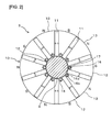
Fig. 2 is a cross-sectional view taken along II-II cross section ofFig. 1 ; -
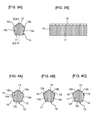
Fig. 3A is a horizontal cross-sectional view showing the shape of an air gap having a wedge portion formed on an inner side of an iron core of the rotor in the radial direction; -
Fig. 3B is a cross-sectional view taken along IIIB-IIIB cross section ofFig. 3A ; -
Fig. 4A is a horizontal cross-sectional view showing the shape of the air gap in a variation in which a plurality of wedge portions is provided; -
Fig. 4B is a horizontal cross-sectional view showing the shape of the air gap in a variation in which a plurality of wedge portions is provided; -
Fig. 4C is a horizontal cross-sectional view showing the shape of the air gap in a variation in which a plurality of wedge portions is provided; -
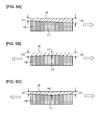
Fig. 5A is a horizontal cross-sectional view showing the shape of the air gap in a variation in which the length of the wedge portion in a direction of protrusion is changed in an axial direction; -
Fig. 5B is a horizontal cross-sectional view showing the shape of the air gap in a variation in which the length of the wedge portion in a direction of protrusion is changed in an axial direction; -
Fig. 5C is a horizontal cross-sectional view showing the shape of the air gap in a variation in which the length of the wedge portion in a direction of protrusion is changed in an axial direction; -
Fig. 6A is a perspective view obtained by extracting the shape of a wedge in a variation in which the width of the wedge portion is changed in the axial direction; -
Fig. 6B is a perspective view obtained by extracting the shape of the wedge in a variation in which the width of the wedge portion is changed in the axial direction; -
Fig. 6C is a perspective view obtained by extracting the shape of the wedge in a variation in which the width of the wedge portion is changed in the axial direction; -
Fig. 7A is a perspective view showing the shape of the air gap in a variation in which the air gap is formed in the shape of a polygon other than a pentagon; -
Fig. 7B is a perspective view showing the shape of the air gap in a variation in which the air gap is formed in the shape of a polygon other than a pentagon; -
Fig. 7C is a perspective view showing the shape of the air gap in a variation in which the air gap is formed in the shape of a polygon other than a pentagon; and -
Fig. 8 is an end surface view of a semi-open type rotor of a variation. - An embodiment will be described below with reference to accompanying drawings.
- An overall configuration of a rotating electrical machine 1 according to the present embodiment will first be described with reference to
Fig. 1 . As shown inFig. 1 , the rotating electrical machine 1 is an inner rotor type motor in which arotor 3 is provided inside astator 2. Thestator 2 and therotor 3 are arranged facing each other in a radial direction of the rotor 3 (in other words, a radial direction of aniron core 10 described later; hereinafter referred simply to as a "radial direction" as necessary) through a magnetic air gap. Specifically, the rotating electrical machine 1 is an IPM (Interior Permanent Magnet) motor in which a permanent magnet is provided within therotor 3.
The rotating electrical machine 1 includes: thestator 2; therotor 3; aframe 4; a load-side bracket 5; a load-side bearing 6; an opposite load-side bracket 7; an opposite load-side bearing 8; ashaft 9; andholding plates 20. Theframe 4 is provided on the above-described outer side of thestator 2 in the radial direction. The load-side bracket 5 is provided on a load side (on the right side inFig. 1 ) end portion of theframe 4. An outer ring of the load-side bearing 6 is fitted to the load-side bracket 5. The opposite load-side bracket 7 is provided on the side opposite to the load side (on the left side inFig. 1 ) end portion of theframe 4. An outer ring of the opposite load-side bearing 8 is fitted to the opposite load-side bracket 7. Both sides of theshaft 9 in an axial direction (in other words, an axial direction of theiron core 10 described later; hereinafter referred simply to as an "axial direction" as necessary) are rotatably supported by the load-side bearing 6 and the opposite load-side bearing 8, respectively. Theholding plate 20 is fixed to theshaft 9 and is butted against one end side (in this example, the load side) of theiron core 10 in the above-described axial direction.
Although one holdingplate 20 is used in this example, two holdingplates 20 may be used at theshaft 9 so as to be butted against one end side and the other end side of theiron core 10 in the above-described axial direction. The holdingplate 20 is butted against one or both of the one end side and the other end side of theiron core 10 in the above-described axial direction, and thereby theiron core 10 is positioned. - The configuration of the
rotor 3 will now be described with reference toFigs. 2 and3 . As shown inFig. 2 , therotor 3 is fixed to the outer circumferential surface of theshaft 9. Therotor 3 includes thecylindrical iron core 10 and a plurality of (in this example, ten)permanent magnets 11 embedded in theiron core 10. - The
iron core 10 integrally includes acylindrical portion 12 andmagnetic pole portions 13. Thecylindrical portion 12 is fixed to theshaft 9. A plurality of (in this example, ten)magnetic pole portions 13 is radially provided on the outer side of thecylindrical portion 12 in the above-described radial direction, according to the number of poles. Theiron core 10 is formed in a laminated body structure in which circular magnetic steel sheets are laminated in the above-described axial direction of theshaft 9. Between the laminated magnetic steel sheets, an insulating layer is inserted. Thepermanent magnet 11 is formed in the shape of a rectangular parallelepiped long in the above-described axial direction of theiron core 10. In thepermanent magnet 11, a cross section perpendicular to the above-described axial direction has a rectangular shape long in the above-described radial direction. Thepermanent magnet 11 is radially arranged within theiron core 10. Thepermanent magnet 11 is fitted into a through hole provided in theiron core 10 in the above-described axial direction and is provided to penetrate theiron core 10. In the outer-side end and the inner-side end of thepermanent magnet 11 in the above-described radial direction, and between the outer circumferential surface and the inner circumferential surface of theiron core 10, narrow gaps are formed. - Each of the
permanent magnets 11 is magnetized in a direction (substantially circumferential direction) perpendicular to the above-described radial direction and the above-described axial direction of theiron core 10. A plurality ofpermanent magnets 11 are arranged such that, in a certainmagnetic pole portion 13, N poles face each other, and that in the nextmagnetic pole portion 13, S poles face each other. Themagnetic pole portion 13 is formed on the outer-side of thecylindrical portion 12 in the above-described radial direction and between the adjacentpermanent magnets 11. Themagnetic pole portion 13 in the location where the N poles of the two adjacentpermanent magnets 11 face each other becomes an N pole; themagnetic pole portion 13 in the location where the S poles of the two adjacentpermanent magnets 11 face each other becomes an S pole. A magnetic flux travels from themagnetic pole portion 13 of the N pole to themagnetic pole portion 13 of the S pole is interlinked with the windings of thestator 2 to generate a rotary torque of therotor 3. - In a portion on the inner side of the
iron core 10 in the above-described radial direction, positioned between the adjacentpermanent magnets 11, anair gap 16 penetrating theiron core 10 in the above-described axial direction is provided. In this example, the horizontal section of theair gap 16 perpendicular to the above-described axial direction is substantially pentagonal. As shown inFigs. 2 and3A , theair gap 16 hasmagnet facing surfaces 16a that face the side surfaces of thepermanent magnets 11, which are magnetic flux generating surfaces and that are in the above-described radial direction, and magnetic flux guide surfaces 16b that are connected to themagnet facing surfaces 16a and that are on the outer side in the above-described radial direction. Themagnet facing surface 16a of theair gap 16 forms a narrow gap between themagnet facing surface 16a and the magnetic flux generating surface of thepermanent magnet 11, and is substantially parallel to the magnetic flux generating surface. Theair gap 16 guides, with the magneticflux guide surface 16b, the magnetic flux of thepermanent magnet 11 in themagnetic pole portion 13 of the N pole to the outer side of therotor 3 in the above-described radial direction. Furthermore, theair gap 16 can reduce, with themagnet facing surface 16a, a leakage magnetic flux to the inner side of therotor 3 in the above-described radial direction between the two adjacentpermanent magnets 11. - As shown in
Fig. 3A , in order for the rigidity of theiron core 10 to be enhanced, theair gap 16 is filled with a resin 17 (an adhesive may be used) as a reinforcing member of a non-magnetic material. Further, in theair gap 16, awedge portion 18 that protrudes to the inner side of theair gap 16 in the above-described radial direction is provided in a corner portion that is the above-described radial direction outer side of the above-described pentagon (that is, a corner portion on the outer side of theair gap 16 in the above-described radial direction, located between the magnetic flux guide surfaces 16b of the air gap 16). The cross section of thewedge portion 18 perpendicular to the above-described axial direction is substantially V-shaped. As shown inFig. 3B , thewedge portion 18 is provided to extend along the above-described axial direction so as to have the same height, and theentire wedge portion 18 in the above-described axial direction is driven into theresin 17 filled in theair gap 16. Thewedge portion 18 is obtained by individually forming a plurality of magnetic steel sheets so as to have wedge portions and laminating a plurality of magnetic steel sheets in the above-described axial direction. - As described above, in the rotating electrical machine 1 of the present embodiment, a plurality of
air gaps 16 is formed in the portion on the inner side of theiron core 10 of the rotor 3above-described in the above-described radial direction, and theair gap 16 is filled with theresin 17. Since theresin 17 is non-magnetic, theair gap 16 filled with theresin 17 can be regarded as an air gap itself magnetically. Hence, the leakage magnetic flux to the inner side of therotor 3 in the above-described radial direction is blocked by theair gap 16, and thus it is possible to reduce the leakage magnetic flux. Then, with theresin 17 filled in theair gap 16, it is possible to prevent the decrease in the rigidity of theiron core 10 caused by provision of theair gap 16. - Furthermore, in the inside of the
air gap 16, thewedge portion 18 whose cross section perpendicular to the above-described axial direction is substantially V-shaped is provided to protrude along the above-described axial direction. In theiron core 10, thewedge portion 18 is provided in theair gap 16, and thus its mechanical strength in theair gap 16 is enhanced. Moreover, the joint between theiron core 10 and theresin 17 is strengthened by the wedge action resulting from thewedge portion 18 being driven into theresin 17 filled in the air gap 16 (that is, the effect that theresin 17 sandwiches and holds thewedge portion 18 from both sides thereof and the effect of increasing the contact area between the inner surface of theair gap 16 and the resin 17). Consequently, it is possible to enhance the rigidity of theiron core 10. - In the present embodiment, in particular, the
wedge portion 18 is provided in the position on the outer side of theair gap 16 in the above-described radial direction within theair gap 16. With the arrangement, the following effects are obtained. Specifically, a centrifugal force resulting from the rotation acts on theiron core 10 of therotor 3. Hence, in each of theair gaps 16, a separation force acting between the filledresin 17 and the inner surface of theair gap 16 is increased in a position in the above-described radial direction outer side of theair gap 16. In the present embodiment, since thewedge portion 18 is provided in the position on the outer side of theair gap 16 in the above-described radial direction, it is possible to obtain a high joint force between theiron core 10 and theresin 17 in the direction of the centrifugal force as a result of the wedge action. As a result, it is possible to prevent theresin 17 from being separated from the inner surface of theair gap 16, and thus it is possible to further increase the effect of enhancing the rigidity of theiron core 10. - Moreover, in the present embodiment, in particular, the cross section of the
air gap 16 perpendicular to the above-described axial direction is pentagonal, and thewedge portion 18 is provided in the above-described pentagonal corner portion of theair gap 16. With the arrangement, the following effects are obtained. Specifically, when the cross section of theair gap 16 is polygonal, stress concentration is more likely to occur in the corner portion where the shape of theair gap 16 is uncontinous, and this may cause a crack or the like. In the present embodiment, since thewedge portion 18 is provided in the corner portion of theair gap 16, it is possible to disperse the stress in the corner portion and alleviate the stress concentration. Hence, it is possible to further increase the effect of enhancing the rigidity of theiron core 10. - Moreover, in the present embodiment, in particular, the
air gap 16 has themagnet facing surfaces 16a and the magnetic flux guide surfaces 16b. With the arrangement, it is possible to efficiently guide the magnetic flux of thepermanent magnets 11 to the outer side of therotor 3 in the above-described radial direction while effectively reducing the leakage magnetic flux to the inner side of therotor 3 in the above-described radial direction. Hence, it is possible to obtain a torque corresponding to the amount of usage of thepermanent magnets 11, and thus it is possible to enhance the motor characteristic of the rotating electrical machine 1. - Moreover, the
wedge portion 18 is provided in the above-described corner portion located between the magnetic flux guide surfaces 16b of theair gap 16, and thus the following effects are obtained. Specifically, since themagnet facing surfaces 16a face the side surfaces of thepermanent magnets 11, which are the magnetic flux generating surfaces, the direction of the magnetic flux is substantially perpendicular to the direction of themagnet facing surfaces 16a. Hence, when thewedge portion 18 is provided in the vicinity of themagnet facing surface 16a, there is a possibility that the magnetic flux passes through the interior of theair gap 16 through thewedge portion 18 and that this causes the leakage magnetic flux to be increased. On the other hand, since the magneticflux guide surface 16b is a surface that guides the magnetic flux of thepermanent magnets 11, the direction of the magnetic flux is substantially parallel to the direction of the magneticflux guide surface 16b. Hence, even when thewedge portion 18 is provided in the vicinity of the magneticflux guide surface 16b, there is little possibility that the magnetic flux passes through the interior of theair gap 16 through thewedge portion 18 and that this does not causes the leakage magnetic flux to be increased. Therefore, thewedge portion 18 is provided in the corner portion located between the magnetic flux guide surfaces 16b, and thus it is possible to enhance the rigidity of theiron core 10 without increasing the leakage magnetic flux. - The embodiment disclosed is not limited to what has been described above; many variations are possible without departing from the spirit and technical ideas thereof. Such variations will be described below.
- In the above-described embodiment, the
wedge portion 18 is provided in only one corner portion of theair gap 16. The present disclosure is not limited to this configuration; thewedge portion 18 can be provided in the other corners of theair gap 16. Examples of such a variation are shown inFigs. 4A to 4C . - In the example shown in
Fig. 4A , thewedge portion 18 is provided not only in the corner portion in the position on the outer side of theair gap 16 having the above-described pentagonal cross section in the above-described radial direction but also in corner portions in positions on the inner side of the pentagon in the above-described radial direction (that is, in the two corner portions located between ashaft facing surface 16c of theair gap 16 that faces theshaft 9 and that is in the above-described radial direction and each of themagnet facing surfaces 16a). As in the above-described embodiment, the cross section of each of thewedge portions 18 perpendicular to the above-described axial direction is substantially V-shaped. Each of thewedge portions 18 is provided to extend along the above-described axial direction. Theair gap 16 is filled with theresin 17. - In the example shown in
Fig. 4B , thewedge portion 18 is provided not only in the corner portion in the position on the outer side of the above-described pentagonal cross section of theair gap 16 in the above-described radial direction but also in corner portions in positions on the side of the side surface of the pentagon (that is, in each of the corner portions located between themagnet facing surfaces 16a of theair gap 16 and the magnetic flux guide surfaces 16b of the air gap 16). - In the example shown in
Fig. 4C , thewedge portions 18 are provided in all the corner portions of theair gap 16 of the above-described pentagonal cross section. - In each of the variations of
Figs. 4A to 4C , a plurality ofwedge portions 18 is provided in theair gap 16, and thus it is possible to further enhance the mechanical strength of theiron core 10 in theair gap 16; moreover, the joint between theiron core 10 and theresin 17 is further strengthened by the wedge action resulting from a plurality ofwedge portions 18 being driven into theresin 17 filled in theair gap 16. Consequently, it is possible to further enhance the rigidity of theiron core 10. - In the above-described embodiment, the length (height) of the
wedge portion 18 in the direction of protrusion is uniform along the above-described axial direction of theair gap 16. The present disclosure is not limited to this configuration; the length of thewedge portion 18 in the direction of protrusion may be changed in the above-described axial direction of theair gap 16. Examples of such a variation are shown inFigs. 5A to 5C . For ease of understanding, inFigs. 5A to 5C , the length (the dimension in an up/down direction of each of the figures) of thewedge portion 18 in the direction of protrusion is exaggerated and shown. - In the example shown in
Fig. 5A , the length of thewedge portion 18 in the direction of protrusion is H1 at one end of theair gap 16 in the above-described axial direction (on the left side inFig. 5A ), and is H2 at the other end of theair gap 16 in the above-described axial direction (on the right side inFig. 5A ) that is longer than H1. In other words, the length of thewedge portion 18 in the direction of protrusion is continuously increased from H1 at one end of theair gap 16 in the above-described axial direction to H2 at the other end in the axial direction. - In the example shown in
Fig. 5B , the length of thewedge portion 18 in the direction of protrusion is H1 at the center portion of theair gap 16 in the above-described axial direction, and is H2 at one end and the other end in the above-described axial direction. In other words, the length of thewedge portion 18 in the direction of protrusion is continuously decreased from H2 at one end of theair gap 16 in the above-described axial direction to H1 at the center portion, and is then continuously increased from H1 at the center portion of theair gap 16 in the above-described axial direction to H2 at the other end in the above-described axial direction. - In the example shown in
Fig. 5C , the length of thewedge portion 18 in the direction of protrusion is H2 at the center portion of theair gap 16 in the above-described axial direction, and is H1 at one end and the other end in the above-described axial direction. In other words, the length of thewedge portion 18 in the direction of protrusion is continuously increased from H1 at one end of theair gap 16 in the above-described axial direction to H2 at the center portion, and is then continuously decreased from H2 at the center portion of theair gap 16 in the above-described axial direction to H1 at the other end in the above-described axial direction. - In each of the variations of
Figs. 5A to 5C , the protrusion length of thewedge portion 18 of theair gap 16 is changed in the above-described axial direction. As a result, the movement of theresin 17 filled in theair gap 16 in the direction in which the protrusion length (height) of thewedge portion 18 is increased is limited. With the arrangement, for example, in the configuration shown inFig. 5A , theresin 17 within theair gap 16 is prevented from moving out to the other side (the right side inFig. 5A ) in the above-described axial direction indicated by a white arrow. In the configuration shown inFigs. 5B and 5C , theresin 17 within theair gap 16 is prevented from moving out to both of one side and the other side (both of the left and right sides inFigs. 5B and 5C ) in the above-described axial direction indicated by white arrows. Consequently, it is possible to stably obtain the effect of enhancing the rigidity of theiron core 10. - In the above-described embodiment, the width of the wedge portion 18 (that is, the width of a base end of the V-shaped cross section of the wedge portion 18) is uniform along the above-described axial direction. The present disclosure is not limited to this configuration; the width of the
wedge portion 18 may be changed in the above-described axial direction of theair gap 16. Examples of such a variation are shown inFigs. 6A to 6C . For ease of understanding, inFigs. 6A to 6C , only thewedge portion 18 is extracted and shown. - In the example shown in
Fig. 6A , the width of thewedge portion 18 is W1 at one end of theair gap 16 in the above-described axial direction (on the left side inFig. 6A ), and is W2 at the other end of theair gap 16 in the above-described axial direction (on the right side inFig. 6A ) that is longer than the W1. In other words, the width of thewedge portion 18 is continuously increased in the above-described axial direction from W1 at one end of theair gap 16 in the above-described axial direction to W2 at the other end. - In the example shown in
Fig. 6B , the width of thewedge portion 18 is W2 at the center portion of theair gap 16 in the above-described axial direction, and is W1 at one end and the other end in the above-described axial direction. In other words, the width of thewedge portion 18 is continuously increased from W1 at one end of theair gap 16 in the above-described axial direction to W2 at the center portion, and is then continuously decreased from W2 at the center portion of theair gap 16 in the above-described axial direction to W1 at the other end in the above-described axial direction. - In the example shown in
Fig. 6C , the width of thewedge portion 18 is W1 at the center portion of theair gap 16 in the above-described axial direction, and is W2 at one end and the other end in the above-described axial direction. In other words, the width of thewedge portion 18 is continuously decreased from W2 at one end of theair gap 16 in the above-described axial direction to W1 at the center portion, and is then continuously increased from W1 at the center portion of theair gap 16 in the above-described axial direction to W2 at the other end in the above-described axial direction. - In each of the variations of
Figs. 6A to 6C , the width of thewedge portion 18 of theair gap 16 is changed in the above-described axial direction. As a result, the movement of theresin 17 filled in theair gap 16 in the direction in which the width of thewedge portion 18 is increased is limited. With the arrangement, in the configuration shown inFig. 6A , theresin 17 within theair gap 16 is prevented from moving out to one side (the right side inFig. 6A ) in the above-described axial direction indicated by a white arrow whereas, in the configuration shown inFigs. 6B and 6C , theresin 17 within theair gap 16 is prevented from moving out to both of one side and the other side (both of the left and right sides inFigs. 6B and 6C ) in the above-described axial direction indicated by white arrows. Consequently, it is possible to stably obtain the effect of enhancing the rigidity of theiron core 10. - In the above-described embodiment, the cross section of the
air gap 16 perpendicular to the above-described axial direction is pentagonal. The present disclosure is not limited to this configuration; the cross section of theair gap 16 may be formed in the shape of a polygon other than a pentagon. Examples of such a variation are shown inFigs. 7A to 7C .
In the example shown inFig. 7A , the cross section of theair gap 16 perpendicular to the above-described axial direction is formed in the shape of a triangle. In theair gap 16, thewedge portion 18 protruding inwardly is provided in the corner portion on the outer side of the triangle in the above-described radial direction, and theair gap 16 is filled with theresin 17. - In the example shown in
Fig. 7B , the above-described horizontal cross section of theair gap 16 is formed in the shape of a quadrangle. In theair gap 16, thewedge portion 18 protruding inwardly is provided in the corner portion on the outer side of the quadrangle in the above-described radial direction. - In the example shown in
Fig. 7C , the above-described horizontal cross section of theair gap 16 is formed in the shape of a hexagon. In theair gap 16, thewedge portion 18 protruding inwardly is provided in each of two corner portions on the outer side of the hexagon in the above-described radial direction. - In the variations of
Figs. 7A to 7C , as in the embodiment described above, it is also possible to enhance the rigidity of theiron core 10. - In the above-described embodiment, the
rotor 3 is a so-called closed type in which the cylindrical outer circumferential portion of theiron core 10 is closed. The present disclosure is not limited to this configuration; a semi-open type configuration in which the cylindrical outer circumferential portion of the iron core is open at places of thepermanent magnets 11 may be applied. An example of such a variation is shown inFig. 8 . - As shown in
Fig. 8 , arotor 3A of the present variation has openingportions 19 in portions on the outer side of thepermanent magnets 11 of aniron core 10A in the above-described radial direction. With the arrangement, therotor 3A is configured to be a semi-open type in which the cylindrical outer circumferential portion of theiron core 10 is not closed. - When the
stator 2 is energized, a magnetic field opposite to the magnetization of the magnet is applied from thestator 2 to thepermanent magnet 11 of therotor 3A, and thus so-called demagnetization occurs in thepermanent magnets 11. Here, a portion to which the maximum magnetic flux is applied from thestator 2 at the time of the above-described energization is the outermost portion of thepermanent magnet 11 of theiron core 10A in the above-described radial direction. Hence, in the present variation, the openingportion 19 is provided in the outermost portion of thepermanent magnet 11 of theiron core 10A in the above-described radial direction, and thus the arrangement in which the demagnetization of thepermanent magnet 11 occurs most significantly is avoided, with the result that the maximum magnetic flux is prevented from being applied from thestator 2 to thepermanent magnet 11 at the time of the above-described energization and that it is possible to reduce the decrease in the rotational characteristic of therotor 3. - The other configurations of the
rotor 3A in the present variation are the same as in therotor 3 in the above-described embodiment. - In the present variation, as in the embodiment described above, it is possible to enhance the rigidity of the
iron core 10A. - Although in the above-described embodiment and each of the variations, the example where the horizontal cross section of the
air gap 16 is polygonal has been described, the present disclosure is not limited to this configuration. That is, the horizontal cross section of theair gap 16 can be formed in an arbitrary shape such as a circle or a sector. Although the rotating electrical machine has been described using the motor as an example, the present disclosure may be applied to a generator. - In addition to what has been described above, the methods of the above-described embodiment and each of the variations may be appropriately combined and utilized. In addition, although not illustrated, in the above-described embodiment and each of the variations, many modifications are possible without departing from the spirit thereof.
Claims (5)
- A rotating electrical machine (1) comprising:a stator (2); anda rotor (3; 3A), characterized in thatthe rotor (3; 3A) includes:a cylindrical iron core (10; 10A) that is fixed to a shaft (9) and comprises a radial direction and an axial direction;a plurality of permanent magnets (11) that is embedded in the iron core (10; 10A);a plurality of air gaps (16) that are respectively provided in a portion on an inner side of the iron core (10; 10A) in the radial direction;a wedge portion (18) that is provided along the axial direction so as to protrude within the air gap (16); anda non-magnetic reinforcing member (17) that is filled in the air gap (16).
- The rotating electrical machine (1) according to claim 1, wherein:the wedge portion (18) is provided in a position at least on an outer side of the air gap (16) in the radial direction within the air gap (16).
- The rotating electrical machine (1) according to claim 1 or 2, wherein:a cross sectional shape of the air gap (16) in a cross section perpendicular to the axial direction is a polygon, andthe wedge portion (18) is provided on a position of a corner portion of the polygon.
- The rotating electrical machine (1) according to claim 3, wherein:the air gap (16) includes:a magnet facing surface (16a) configured to face a side surface which is a magnetic flux generating surface of the permanent magnet (11) and to reduce a leakage magnetic flux to the inner side of the rotor (3; 3A) in the radial direction; anda magnetic flux guide surface (16b) configured to guide a magnetic flux of the permanent magnet (11) to the outer side of the rotor (3; 3A) in the radial direction, andthe wedge portion (18) is provided on the corner portion located between the two magnetic flux guide surfaces (16b).
- The rotating electrical machine (1) according to any one of claims 1 to 4, wherein:the wedge portion (18) is formed such that at least one of a length along a direction of protrusion and a length along a circumferential direction is changed in the axial direction.
Applications Claiming Priority (1)
| Application Number | Priority Date | Filing Date | Title |
|---|---|---|---|
| JP2012232599A JP5594492B2 (en) | 2012-10-22 | 2012-10-22 | Rotating electric machine |
Publications (2)
| Publication Number | Publication Date |
|---|---|
| EP2722969A1 true EP2722969A1 (en) | 2014-04-23 |
| EP2722969B1 EP2722969B1 (en) | 2016-01-06 |
Family
ID=48143505
Family Applications (1)
| Application Number | Title | Priority Date | Filing Date |
|---|---|---|---|
| EP13164620.0A Not-in-force EP2722969B1 (en) | 2012-10-22 | 2013-04-22 | Rotating electrical machine |
Country Status (6)
| Country | Link |
|---|---|
| US (1) | US9219390B2 (en) |
| EP (1) | EP2722969B1 (en) |
| JP (1) | JP5594492B2 (en) |
| KR (1) | KR101477904B1 (en) |
| CN (1) | CN103779986B (en) |
| BR (1) | BR102013011376A2 (en) |
Cited By (1)
| Publication number | Priority date | Publication date | Assignee | Title |
|---|---|---|---|---|
| US11522397B2 (en) * | 2018-08-09 | 2022-12-06 | Zhuhai Kaibang Motor Co., Ltd. | Motor rotor and permanent magnet motor |
Families Citing this family (10)
| Publication number | Priority date | Publication date | Assignee | Title |
|---|---|---|---|---|
| WO2015189896A1 (en) * | 2014-06-09 | 2015-12-17 | 株式会社安川電機 | Rotating electric machine, rotating electric machine control device, rotating electric machine control method |
| WO2017037840A1 (en) * | 2015-08-31 | 2017-03-09 | 圀博 三宅 | Power generation device and stator module |
| DE102015015337B4 (en) * | 2015-09-01 | 2018-06-21 | Abp Induction Systems Gmbh | Induction crucible furnace and magnetic conclusion for this |
| JP6673707B2 (en) * | 2016-02-03 | 2020-03-25 | 日本電産サンキョー株式会社 | Interior magnet type motor |
| DE102017218152A1 (en) * | 2017-10-11 | 2019-04-11 | Baumüller Nürnberg GmbH | Rotor of an electric machine |
| CN108768024B (en) * | 2018-08-15 | 2025-03-11 | 珠海格力节能环保制冷技术研究中心有限公司 | Motor rotors and permanent magnet motors |
| CN108768025B (en) * | 2018-08-15 | 2024-11-29 | 珠海格力节能环保制冷技术研究中心有限公司 | Motor rotor and permanent magnet motor |
| KR102321727B1 (en) * | 2019-11-07 | 2021-11-03 | 호남대학교 산학협력단 | Consequent pole motor |
| US12266977B2 (en) * | 2020-04-15 | 2025-04-01 | Panasonic Intellectual Property Management Co., Ltd. | Rotor and electric motor |
| CN115733265A (en) * | 2021-08-31 | 2023-03-03 | 无锡东精电微电机有限公司 | Rotating electrical machine |
Citations (4)
| Publication number | Priority date | Publication date | Assignee | Title |
|---|---|---|---|---|
| WO2008078584A1 (en) | 2006-12-27 | 2008-07-03 | Kabushiki Kaisha Yaskawa Denki | Buried magnet motor |
| WO2009153511A2 (en) * | 2008-06-16 | 2009-12-23 | Moteurs Leroy-Somer | Permanent magnet rotor, and rotating machine comprising such a rotor |
| WO2011114594A1 (en) * | 2010-03-15 | 2011-09-22 | 株式会社安川電機 | Permanent magnet-type rotary generator |
| US20120038237A1 (en) * | 2010-08-10 | 2012-02-16 | Yue Li | Brushless motor |
Family Cites Families (3)
| Publication number | Priority date | Publication date | Assignee | Title |
|---|---|---|---|---|
| JPH11103546A (en) * | 1997-09-29 | 1999-04-13 | Fujitsu General Ltd | Permanent magnet motor |
| JP2001359249A (en) * | 2000-06-13 | 2001-12-26 | Meidensha Corp | Rotating electric machine rotor |
| JP2012080607A (en) * | 2010-09-30 | 2012-04-19 | Aisin Aw Co Ltd | Rotor for rotary electric machine |
-
2012
- 2012-10-22 JP JP2012232599A patent/JP5594492B2/en not_active Expired - Fee Related
-
2013
- 2013-03-14 US US13/802,802 patent/US9219390B2/en not_active Expired - Fee Related
- 2013-04-22 EP EP13164620.0A patent/EP2722969B1/en not_active Not-in-force
- 2013-05-08 BR BR102013011376-0A patent/BR102013011376A2/en not_active IP Right Cessation
- 2013-05-16 KR KR1020130055901A patent/KR101477904B1/en not_active Expired - Fee Related
- 2013-05-17 CN CN201310184423.9A patent/CN103779986B/en not_active Expired - Fee Related
Patent Citations (4)
| Publication number | Priority date | Publication date | Assignee | Title |
|---|---|---|---|---|
| WO2008078584A1 (en) | 2006-12-27 | 2008-07-03 | Kabushiki Kaisha Yaskawa Denki | Buried magnet motor |
| WO2009153511A2 (en) * | 2008-06-16 | 2009-12-23 | Moteurs Leroy-Somer | Permanent magnet rotor, and rotating machine comprising such a rotor |
| WO2011114594A1 (en) * | 2010-03-15 | 2011-09-22 | 株式会社安川電機 | Permanent magnet-type rotary generator |
| US20120038237A1 (en) * | 2010-08-10 | 2012-02-16 | Yue Li | Brushless motor |
Cited By (1)
| Publication number | Priority date | Publication date | Assignee | Title |
|---|---|---|---|---|
| US11522397B2 (en) * | 2018-08-09 | 2022-12-06 | Zhuhai Kaibang Motor Co., Ltd. | Motor rotor and permanent magnet motor |
Also Published As
| Publication number | Publication date |
|---|---|
| JP5594492B2 (en) | 2014-09-24 |
| BR102013011376A2 (en) | 2014-11-04 |
| CN103779986A (en) | 2014-05-07 |
| EP2722969B1 (en) | 2016-01-06 |
| US20140111053A1 (en) | 2014-04-24 |
| CN103779986B (en) | 2016-08-03 |
| JP2014087117A (en) | 2014-05-12 |
| KR20140051759A (en) | 2014-05-02 |
| KR101477904B1 (en) | 2014-12-31 |
| US9219390B2 (en) | 2015-12-22 |
Similar Documents
| Publication | Publication Date | Title |
|---|---|---|
| EP2722969B1 (en) | Rotating electrical machine | |
| US9577483B2 (en) | Rotor for a permanent-magnet embedded motor having permanent magnets fitted into a plurality of magnet insertion holes formed in a circumferential direction | |
| JP5677584B2 (en) | Rotor, compressor and refrigeration air conditioner for embedded permanent magnet motor | |
| JP2008206308A (en) | Permanent-magnet rotating electric machine | |
| JP5208088B2 (en) | Permanent magnet embedded motor and blower | |
| JP2016174461A (en) | Rotor | |
| JP2014003841A (en) | Rotor and rotary electric machine using the same | |
| JP2008211934A (en) | Rotating electrical machine and rotator therefor | |
| JP5014364B2 (en) | Permanent magnet motor rotor | |
| CN108475972A (en) | Rotor, Magnitizing method, motor and screw compressor | |
| JP6156122B2 (en) | Rotor structure of embedded magnet motor | |
| EP3386075B1 (en) | Electric motor with permament magnet and compressor having the same | |
| JP6112970B2 (en) | Permanent magnet rotating electric machine | |
| JP2013132124A (en) | Core for field element | |
| JP5920025B2 (en) | Magnetizing apparatus for rotor and magnetizing method for rotor | |
| JP5959616B2 (en) | Rotor, compressor and refrigeration air conditioner for embedded permanent magnet motor | |
| JP2013051837A (en) | Rotary electric machine | |
| JP2014113033A (en) | Embedded magnet dynamo-electric machine | |
| JP2008187802A (en) | Rotor for rotary electrical machine, and electric machine | |
| JP6080734B2 (en) | Rotating electric machine and elevator hoisting machine | |
| JP2014143797A (en) | Magnet embedded rotary electric machine | |
| JP6330425B2 (en) | Rotating electrical machine | |
| CN105914998A (en) | Embedded double radial permanent magnetic and salient pole electromagnetic mixing excitation driving motor | |
| JP2014161206A (en) | Interior magnet type rotating electrical machine | |
| JP2014060821A (en) | Ipm motor |
Legal Events
| Date | Code | Title | Description |
|---|---|---|---|
| PUAI | Public reference made under article 153(3) epc to a published international application that has entered the european phase |
Free format text: ORIGINAL CODE: 0009012 |
|
| AK | Designated contracting states |
Kind code of ref document: A1 Designated state(s): AL AT BE BG CH CY CZ DE DK EE ES FI FR GB GR HR HU IE IS IT LI LT LU LV MC MK MT NL NO PL PT RO RS SE SI SK SM TR |
|
| AX | Request for extension of the european patent |
Extension state: BA ME |
|
| 17P | Request for examination filed |
Effective date: 20140519 |
|
| RBV | Designated contracting states (corrected) |
Designated state(s): AL AT BE BG CH CY CZ DE DK EE ES FI FR GB GR HR HU IE IS IT LI LT LU LV MC MK MT NL NO PL PT RO RS SE SI SK SM TR |
|
| GRAP | Despatch of communication of intention to grant a patent |
Free format text: ORIGINAL CODE: EPIDOSNIGR1 |
|
| INTG | Intention to grant announced |
Effective date: 20150619 |
|
| GRAR | Information related to intention to grant a patent recorded |
Free format text: ORIGINAL CODE: EPIDOSNIGR71 |
|
| GRAS | Grant fee paid |
Free format text: ORIGINAL CODE: EPIDOSNIGR3 |
|
| GRAA | (expected) grant |
Free format text: ORIGINAL CODE: 0009210 |
|
| INTG | Intention to grant announced |
Effective date: 20151109 |
|
| AK | Designated contracting states |
Kind code of ref document: B1 Designated state(s): AL AT BE BG CH CY CZ DE DK EE ES FI FR GB GR HR HU IE IS IT LI LT LU LV MC MK MT NL NO PL PT RO RS SE SI SK SM TR |
|
| REG | Reference to a national code |
Ref country code: GB Ref legal event code: FG4D |
|
| REG | Reference to a national code |
Ref country code: CH Ref legal event code: EP |
|
| REG | Reference to a national code |
Ref country code: IE Ref legal event code: FG4D |
|
| REG | Reference to a national code |
Ref country code: AT Ref legal event code: REF Ref document number: 769617 Country of ref document: AT Kind code of ref document: T Effective date: 20160215 |
|
| REG | Reference to a national code |
Ref country code: DE Ref legal event code: R096 Ref document number: 602013004426 Country of ref document: DE |
|
| REG | Reference to a national code |
Ref country code: LT Ref legal event code: MG4D |
|
| REG | Reference to a national code |
Ref country code: NL Ref legal event code: MP Effective date: 20160106 |
|
| REG | Reference to a national code |
Ref country code: AT Ref legal event code: MK05 Ref document number: 769617 Country of ref document: AT Kind code of ref document: T Effective date: 20160106 |
|
| PG25 | Lapsed in a contracting state [announced via postgrant information from national office to epo] |
Ref country code: NL Free format text: LAPSE BECAUSE OF FAILURE TO SUBMIT A TRANSLATION OF THE DESCRIPTION OR TO PAY THE FEE WITHIN THE PRESCRIBED TIME-LIMIT Effective date: 20160106 |
|
| PG25 | Lapsed in a contracting state [announced via postgrant information from national office to epo] |
Ref country code: NO Free format text: LAPSE BECAUSE OF FAILURE TO SUBMIT A TRANSLATION OF THE DESCRIPTION OR TO PAY THE FEE WITHIN THE PRESCRIBED TIME-LIMIT Effective date: 20160406 Ref country code: HR Free format text: LAPSE BECAUSE OF FAILURE TO SUBMIT A TRANSLATION OF THE DESCRIPTION OR TO PAY THE FEE WITHIN THE PRESCRIBED TIME-LIMIT Effective date: 20160106 Ref country code: FI Free format text: LAPSE BECAUSE OF FAILURE TO SUBMIT A TRANSLATION OF THE DESCRIPTION OR TO PAY THE FEE WITHIN THE PRESCRIBED TIME-LIMIT Effective date: 20160106 Ref country code: IT Free format text: LAPSE BECAUSE OF FAILURE TO SUBMIT A TRANSLATION OF THE DESCRIPTION OR TO PAY THE FEE WITHIN THE PRESCRIBED TIME-LIMIT Effective date: 20160106 Ref country code: ES Free format text: LAPSE BECAUSE OF FAILURE TO SUBMIT A TRANSLATION OF THE DESCRIPTION OR TO PAY THE FEE WITHIN THE PRESCRIBED TIME-LIMIT Effective date: 20160106 Ref country code: GR Free format text: LAPSE BECAUSE OF FAILURE TO SUBMIT A TRANSLATION OF THE DESCRIPTION OR TO PAY THE FEE WITHIN THE PRESCRIBED TIME-LIMIT Effective date: 20160407 |
|
| PG25 | Lapsed in a contracting state [announced via postgrant information from national office to epo] |
Ref country code: IS Free format text: LAPSE BECAUSE OF FAILURE TO SUBMIT A TRANSLATION OF THE DESCRIPTION OR TO PAY THE FEE WITHIN THE PRESCRIBED TIME-LIMIT Effective date: 20160506 Ref country code: BE Free format text: LAPSE BECAUSE OF NON-PAYMENT OF DUE FEES Effective date: 20160430 Ref country code: SE Free format text: LAPSE BECAUSE OF FAILURE TO SUBMIT A TRANSLATION OF THE DESCRIPTION OR TO PAY THE FEE WITHIN THE PRESCRIBED TIME-LIMIT Effective date: 20160106 Ref country code: RS Free format text: LAPSE BECAUSE OF FAILURE TO SUBMIT A TRANSLATION OF THE DESCRIPTION OR TO PAY THE FEE WITHIN THE PRESCRIBED TIME-LIMIT Effective date: 20160106 Ref country code: PL Free format text: LAPSE BECAUSE OF FAILURE TO SUBMIT A TRANSLATION OF THE DESCRIPTION OR TO PAY THE FEE WITHIN THE PRESCRIBED TIME-LIMIT Effective date: 20160106 Ref country code: AT Free format text: LAPSE BECAUSE OF FAILURE TO SUBMIT A TRANSLATION OF THE DESCRIPTION OR TO PAY THE FEE WITHIN THE PRESCRIBED TIME-LIMIT Effective date: 20160106 Ref country code: LV Free format text: LAPSE BECAUSE OF FAILURE TO SUBMIT A TRANSLATION OF THE DESCRIPTION OR TO PAY THE FEE WITHIN THE PRESCRIBED TIME-LIMIT Effective date: 20160106 Ref country code: PT Free format text: LAPSE BECAUSE OF FAILURE TO SUBMIT A TRANSLATION OF THE DESCRIPTION OR TO PAY THE FEE WITHIN THE PRESCRIBED TIME-LIMIT Effective date: 20160506 Ref country code: LT Free format text: LAPSE BECAUSE OF FAILURE TO SUBMIT A TRANSLATION OF THE DESCRIPTION OR TO PAY THE FEE WITHIN THE PRESCRIBED TIME-LIMIT Effective date: 20160106 |
|
| REG | Reference to a national code |
Ref country code: DE Ref legal event code: R097 Ref document number: 602013004426 Country of ref document: DE |
|
| PG25 | Lapsed in a contracting state [announced via postgrant information from national office to epo] |
Ref country code: EE Free format text: LAPSE BECAUSE OF FAILURE TO SUBMIT A TRANSLATION OF THE DESCRIPTION OR TO PAY THE FEE WITHIN THE PRESCRIBED TIME-LIMIT Effective date: 20160106 Ref country code: DK Free format text: LAPSE BECAUSE OF FAILURE TO SUBMIT A TRANSLATION OF THE DESCRIPTION OR TO PAY THE FEE WITHIN THE PRESCRIBED TIME-LIMIT Effective date: 20160106 |
|
| PLBE | No opposition filed within time limit |
Free format text: ORIGINAL CODE: 0009261 |
|
| STAA | Information on the status of an ep patent application or granted ep patent |
Free format text: STATUS: NO OPPOSITION FILED WITHIN TIME LIMIT |
|
| PG25 | Lapsed in a contracting state [announced via postgrant information from national office to epo] |
Ref country code: RO Free format text: LAPSE BECAUSE OF FAILURE TO SUBMIT A TRANSLATION OF THE DESCRIPTION OR TO PAY THE FEE WITHIN THE PRESCRIBED TIME-LIMIT Effective date: 20160106 Ref country code: CZ Free format text: LAPSE BECAUSE OF FAILURE TO SUBMIT A TRANSLATION OF THE DESCRIPTION OR TO PAY THE FEE WITHIN THE PRESCRIBED TIME-LIMIT Effective date: 20160106 Ref country code: SK Free format text: LAPSE BECAUSE OF FAILURE TO SUBMIT A TRANSLATION OF THE DESCRIPTION OR TO PAY THE FEE WITHIN THE PRESCRIBED TIME-LIMIT Effective date: 20160106 Ref country code: SM Free format text: LAPSE BECAUSE OF FAILURE TO SUBMIT A TRANSLATION OF THE DESCRIPTION OR TO PAY THE FEE WITHIN THE PRESCRIBED TIME-LIMIT Effective date: 20160106 |
|
| REG | Reference to a national code |
Ref country code: CH Ref legal event code: PL |
|
| 26N | No opposition filed |
Effective date: 20161007 |
|
| PG25 | Lapsed in a contracting state [announced via postgrant information from national office to epo] |
Ref country code: LU Free format text: LAPSE BECAUSE OF FAILURE TO SUBMIT A TRANSLATION OF THE DESCRIPTION OR TO PAY THE FEE WITHIN THE PRESCRIBED TIME-LIMIT Effective date: 20160422 Ref country code: BE Free format text: LAPSE BECAUSE OF FAILURE TO SUBMIT A TRANSLATION OF THE DESCRIPTION OR TO PAY THE FEE WITHIN THE PRESCRIBED TIME-LIMIT Effective date: 20160106 |
|
| REG | Reference to a national code |
Ref country code: IE Ref legal event code: MM4A |
|
| REG | Reference to a national code |
Ref country code: FR Ref legal event code: ST Effective date: 20161230 |
|
| PG25 | Lapsed in a contracting state [announced via postgrant information from national office to epo] |
Ref country code: FR Free format text: LAPSE BECAUSE OF NON-PAYMENT OF DUE FEES Effective date: 20160502 Ref country code: CH Free format text: LAPSE BECAUSE OF NON-PAYMENT OF DUE FEES Effective date: 20160430 Ref country code: LI Free format text: LAPSE BECAUSE OF NON-PAYMENT OF DUE FEES Effective date: 20160430 |
|
| PG25 | Lapsed in a contracting state [announced via postgrant information from national office to epo] |
Ref country code: BG Free format text: LAPSE BECAUSE OF FAILURE TO SUBMIT A TRANSLATION OF THE DESCRIPTION OR TO PAY THE FEE WITHIN THE PRESCRIBED TIME-LIMIT Effective date: 20160406 Ref country code: SI Free format text: LAPSE BECAUSE OF FAILURE TO SUBMIT A TRANSLATION OF THE DESCRIPTION OR TO PAY THE FEE WITHIN THE PRESCRIBED TIME-LIMIT Effective date: 20160106 |
|
| PG25 | Lapsed in a contracting state [announced via postgrant information from national office to epo] |
Ref country code: IE Free format text: LAPSE BECAUSE OF NON-PAYMENT OF DUE FEES Effective date: 20160422 |
|
| GBPC | Gb: european patent ceased through non-payment of renewal fee |
Effective date: 20170422 |
|
| PG25 | Lapsed in a contracting state [announced via postgrant information from national office to epo] |
Ref country code: GB Free format text: LAPSE BECAUSE OF NON-PAYMENT OF DUE FEES Effective date: 20170422 |
|
| PG25 | Lapsed in a contracting state [announced via postgrant information from national office to epo] |
Ref country code: HU Free format text: LAPSE BECAUSE OF FAILURE TO SUBMIT A TRANSLATION OF THE DESCRIPTION OR TO PAY THE FEE WITHIN THE PRESCRIBED TIME-LIMIT; INVALID AB INITIO Effective date: 20130422 |
|
| PG25 | Lapsed in a contracting state [announced via postgrant information from national office to epo] |
Ref country code: MK Free format text: LAPSE BECAUSE OF FAILURE TO SUBMIT A TRANSLATION OF THE DESCRIPTION OR TO PAY THE FEE WITHIN THE PRESCRIBED TIME-LIMIT Effective date: 20160106 Ref country code: MC Free format text: LAPSE BECAUSE OF FAILURE TO SUBMIT A TRANSLATION OF THE DESCRIPTION OR TO PAY THE FEE WITHIN THE PRESCRIBED TIME-LIMIT Effective date: 20160106 Ref country code: MT Free format text: LAPSE BECAUSE OF NON-PAYMENT OF DUE FEES Effective date: 20160430 Ref country code: TR Free format text: LAPSE BECAUSE OF FAILURE TO SUBMIT A TRANSLATION OF THE DESCRIPTION OR TO PAY THE FEE WITHIN THE PRESCRIBED TIME-LIMIT Effective date: 20160106 Ref country code: CY Free format text: LAPSE BECAUSE OF FAILURE TO SUBMIT A TRANSLATION OF THE DESCRIPTION OR TO PAY THE FEE WITHIN THE PRESCRIBED TIME-LIMIT Effective date: 20160106 |
|
| PG25 | Lapsed in a contracting state [announced via postgrant information from national office to epo] |
Ref country code: AL Free format text: LAPSE BECAUSE OF FAILURE TO SUBMIT A TRANSLATION OF THE DESCRIPTION OR TO PAY THE FEE WITHIN THE PRESCRIBED TIME-LIMIT Effective date: 20160106 |
|
| PGFP | Annual fee paid to national office [announced via postgrant information from national office to epo] |
Ref country code: DE Payment date: 20190410 Year of fee payment: 7 |
|
| REG | Reference to a national code |
Ref country code: DE Ref legal event code: R119 Ref document number: 602013004426 Country of ref document: DE |
|
| PG25 | Lapsed in a contracting state [announced via postgrant information from national office to epo] |
Ref country code: DE Free format text: LAPSE BECAUSE OF NON-PAYMENT OF DUE FEES Effective date: 20201103 |