EP2722964A2 - Double source battery charger - Google Patents
Double source battery charger Download PDFInfo
- Publication number
- EP2722964A2 EP2722964A2 EP13189776.1A EP13189776A EP2722964A2 EP 2722964 A2 EP2722964 A2 EP 2722964A2 EP 13189776 A EP13189776 A EP 13189776A EP 2722964 A2 EP2722964 A2 EP 2722964A2
- Authority
- EP
- European Patent Office
- Prior art keywords
- battery
- alternator
- external power
- output
- battery charger
- Prior art date
- Legal status (The legal status is an assumption and is not a legal conclusion. Google has not performed a legal analysis and makes no representation as to the accuracy of the status listed.)
- Withdrawn
Links
Images


Classifications
-
- F—MECHANICAL ENGINEERING; LIGHTING; HEATING; WEAPONS; BLASTING
- F02—COMBUSTION ENGINES; HOT-GAS OR COMBUSTION-PRODUCT ENGINE PLANTS
- F02N—STARTING OF COMBUSTION ENGINES; STARTING AIDS FOR SUCH ENGINES, NOT OTHERWISE PROVIDED FOR
- F02N11/00—Starting of engines by means of electric motors
- F02N11/08—Circuits or control means specially adapted for starting of engines
- F02N11/0862—Circuits or control means specially adapted for starting of engines characterised by the electrical power supply means, e.g. battery
-
- H—ELECTRICITY
- H02—GENERATION; CONVERSION OR DISTRIBUTION OF ELECTRIC POWER
- H02J—CIRCUIT ARRANGEMENTS OR SYSTEMS FOR SUPPLYING OR DISTRIBUTING ELECTRIC POWER; SYSTEMS FOR STORING ELECTRIC ENERGY
- H02J5/00—Circuit arrangements for transfer of electric power between ac networks and dc networks
-
- H—ELECTRICITY
- H02—GENERATION; CONVERSION OR DISTRIBUTION OF ELECTRIC POWER
- H02J—CIRCUIT ARRANGEMENTS OR SYSTEMS FOR SUPPLYING OR DISTRIBUTING ELECTRIC POWER; SYSTEMS FOR STORING ELECTRIC ENERGY
- H02J7/00—Circuit arrangements for charging or depolarising batteries or for supplying loads from batteries
- H02J7/02—Circuit arrangements for charging or depolarising batteries or for supplying loads from batteries for charging batteries from ac mains by converters
-
- H—ELECTRICITY
- H02—GENERATION; CONVERSION OR DISTRIBUTION OF ELECTRIC POWER
- H02J—CIRCUIT ARRANGEMENTS OR SYSTEMS FOR SUPPLYING OR DISTRIBUTING ELECTRIC POWER; SYSTEMS FOR STORING ELECTRIC ENERGY
- H02J7/00—Circuit arrangements for charging or depolarising batteries or for supplying loads from batteries
- H02J7/14—Circuit arrangements for charging or depolarising batteries or for supplying loads from batteries for charging batteries from dynamo-electric generators driven at varying speed, e.g. on vehicle
- H02J7/1415—Circuit arrangements for charging or depolarising batteries or for supplying loads from batteries for charging batteries from dynamo-electric generators driven at varying speed, e.g. on vehicle with a generator driven by a prime mover other than the motor of a vehicle
-
- F—MECHANICAL ENGINEERING; LIGHTING; HEATING; WEAPONS; BLASTING
- F02—COMBUSTION ENGINES; HOT-GAS OR COMBUSTION-PRODUCT ENGINE PLANTS
- F02N—STARTING OF COMBUSTION ENGINES; STARTING AIDS FOR SUCH ENGINES, NOT OTHERWISE PROVIDED FOR
- F02N11/00—Starting of engines by means of electric motors
- F02N11/08—Circuits or control means specially adapted for starting of engines
- F02N11/0862—Circuits or control means specially adapted for starting of engines characterised by the electrical power supply means, e.g. battery
- F02N11/0866—Circuits or control means specially adapted for starting of engines characterised by the electrical power supply means, e.g. battery comprising several power sources, e.g. battery and capacitor or two batteries
-
- F—MECHANICAL ENGINEERING; LIGHTING; HEATING; WEAPONS; BLASTING
- F02—COMBUSTION ENGINES; HOT-GAS OR COMBUSTION-PRODUCT ENGINE PLANTS
- F02N—STARTING OF COMBUSTION ENGINES; STARTING AIDS FOR SUCH ENGINES, NOT OTHERWISE PROVIDED FOR
- F02N11/00—Starting of engines by means of electric motors
- F02N11/14—Starting of engines by means of electric starters with external current supply
-
- H—ELECTRICITY
- H02—GENERATION; CONVERSION OR DISTRIBUTION OF ELECTRIC POWER
- H02J—CIRCUIT ARRANGEMENTS OR SYSTEMS FOR SUPPLYING OR DISTRIBUTING ELECTRIC POWER; SYSTEMS FOR STORING ELECTRIC ENERGY
- H02J2207/00—Indexing scheme relating to details of circuit arrangements for charging or depolarising batteries or for supplying loads from batteries
- H02J2207/10—Control circuit supply, e.g. means for supplying power to the control circuit
-
- H—ELECTRICITY
- H02—GENERATION; CONVERSION OR DISTRIBUTION OF ELECTRIC POWER
- H02J—CIRCUIT ARRANGEMENTS OR SYSTEMS FOR SUPPLYING OR DISTRIBUTING ELECTRIC POWER; SYSTEMS FOR STORING ELECTRIC ENERGY
- H02J2207/00—Indexing scheme relating to details of circuit arrangements for charging or depolarising batteries or for supplying loads from batteries
- H02J2207/40—Indexing scheme relating to details of circuit arrangements for charging or depolarising batteries or for supplying loads from batteries adapted for charging from various sources, e.g. AC, DC or multivoltage
Definitions
- the invention relates to battery chargers and engine-generators.
- Engine-generators also referred to as gen-sets, generally include an internal combustion engine that drives an alternator to generate electricity.
- the alternator includes a rotor and a stator.
- a drive shaft of the engine rotationally drives the rotor, which induces current in the stator.
- the induced current forms the output of the generator.
- the invention provides a double source battery charger for an engine-generator having an electric starter and a battery.
- the electric starter for the engine-generator is selectively energized by the battery to start an engine of the engine-generator.
- the double source charger maintains the battery at a desired charge such that the battery has sufficient charge to energize the electric starter.
- the double source battery charger is selectively coupled to two power sources to charge the battery: an alternator of the engine-generator and an external AC source, such as a standard 120 Volt or 240 Volt wall outlet. As a result, the battery is charged by either a wall outlet or, if the generator is running, by power provided from the alternator.
- the invention provides a method of charging a battery in a generator having a double source battery charger, an electric starter motor, an internal combustion engine, and an external power connector.
- the method includes coupling the battery to the electric starter motor to start the internal combustion engine and driving an alternator, by the internal combustion engine, to produce alternator output power.
- the method further includes detecting at least one of a presence of the alternator output power and an absence of external power from the external power source connector and, in response, controlling a switch to connect the alternator to the double source battery charger.
- the battery is then charged by the double source battery charger using the alternator output power from the alternator.
- the method also includes detecting at least one of an absence of the alternator output power and a presence of external power from the external power connector, and, in response, controlling the switch to connect the external power source connector to the double source battery charger.
- the battery is then charged by the double source battery charger using the external power from the external power connector.
- the invention provides a generator having a double source battery charger, a battery, an internal combustion engine, and an electric starter motor selectively coupled to the battery to start the internal combustion engine.
- the generator further includes an alternator having a rotor driven by the internal combustion engine and a stator in which alternator output power is induced when the rotor is driven.
- the alternator output power is provided at an alternator output.
- the generator also includes an external power source connector, a switch, and a battery charger.
- the external power source connector is operable to be coupled to an external power source and to provide external power at a connector output.
- the switch has a first input coupled to the alternator output, a second input coupled to the connector output, and a switch output.
- the battery charger is coupled to the battery and operable to charge the battery.
- the battery charger further has a power input coupled to the switch output such that the battery charger is selectively coupled, via the switch, to one of the alternator output and connector output to charge the battery using one of the alternator output power and the
- the invention provides a method of charging a battery in a generator having a double source battery charger, an internal combustion engine, an electric starter motor selectively coupled to the battery to start the internal combustion engine, an alternator driven by the internal combustion engine to produce alternator output power, and an external power source connector operable to be coupled to an external power source to provide external power.
- the method includes detecting whether at least one of the alternator is producing alternator output power and the external power source connector is providing external power.
- the method further includes connecting one of the alternator and the external power source connector to an input of the double source battery charger based on the detection.
- the method also includes charging the battery, by the double source battery charger, using power received at the input from the connected one of the alternator and the external power source connector.
- Figs. 1A-E depict a generator with a double source battery charger according to an embodiment of the invention.
- FIG. 2 depicts a block diagram of the generator system.
- FIG. 3 depicts a double source battery charger circuit.
- FIG. 4 illustrates a charging profile of the double source battery charger with three modes of operation.
- Figs. 5A-B depict flow charts for the double source battery charger input source.
- embodiments of the invention may include hardware, software, and electronic components or modules that, for purposes of discussion, may be illustrated and described as if the majority of the components were implemented solely in hardware.
- the electronic based aspects of the invention may be implemented in software (e.g., stored on non-transitory computer-readable medium) executable by one or more processors.
- controllers can include standard processing components, such as one or more processors, one or more computer-readable medium modules, one or more input/output interfaces, and various connections (e.g., a system bus) connecting the components.
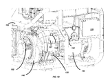
- a generator 100 including a frame 105 having a folding handle 110 pivotable about hinge 115 to fold forward and down to meet the top side of the generator 100.
- the generator 100 further includes a fuel tank 120 with a fuel cap 122, a rechargeable battery 125, a main panel 130, an electric starter motor 135, an internal combustion engine 140, and an alternator 145.
- two or more wheels are secured to the bottom of the frame 105 to ease in the transport of the generator 100.
- the generator 100 also includes a socket 150 for coupling to a wall outlet connector to charge the battery 125.
- the generator 100 further includes a pull starter cord 155 (shown without a grip handle) to optionally start the engine 140 without the use of the battery 125 and electric starter 135.
- the generator 100 includes a starter switch 156 to couple the electric starter 135 to the battery 125, and a fuel valve 158 to open/close a fuel supply line connecting the fuel tank 120 to the engine 140.
- the generator 100 also includes an idle control switch 157 to alter an idle control mode of the generator 100.
- the main panel 130 is positioned adjacent to the fuel tank 120 and above the electric starter 135 and engine 140.
- the main panel 130 includes four AC outlets 160, each having terminals for connecting to a three prong plug of an AC load.
- the AC outlets 160 are ground fault circuit interrupter (GFCI) outlets, although other outlet types may be included.
- the main panel 130 further includes a 120/240 Volt AC outlet 165.
- the AC outlets 160 and 165 are protected from water and contaminant (e.g., dust) infiltration via covers (not shown), which may be made of rubber or another suitable material.
- DC outlets are also provided on the main panel 130 or elsewhere on the generator 100.
- the generator 100 further includes a double source battery charger 225, a generator output module 230, and a controller 235.
- the engine 140 rotates an output shaft 240 when enabled, which rotates a rotor (not shown) of the alternator 145.
- the rotating rotor induces an AC output from a stator (not shown) of the alternator 145.
- the AC output by the alternator 145 is received by the generator output module 230 and the double source battery charger 225.
- the generator output module 230 conditions the AC power received from the alternator 145 to output to one or more AC loads 255 and/or DC loads (not shown).
- the generator output module 230 includes a rectifier, inverter, and filtering components (not shown).
- the rectifier receives and rectifies the AC power output from the alternator 145 and outputs DC power to the inverter.
- the inverter then inverts the DC power and outputs the AC power to the filtering components.
- the filtering components assist in removing ripple, noise, etc. from the AC output by the inverter to provide a clean AC power signal to one or more AC loads 255.
- the generator output module 230 filters the AC signal from the alternator 145 and provides the filtered AC signal to the AC loads 255 without the additional rectifier and inverter stages.
- the AC loads 255 are coupled to the generator 100 via, for instance, a two or three-prong AC outlet (e.g., AC outlets 160) of the generator 100.
- Rectifier circuitry within the generator output module 230 rectifies the AC output from the alternator 145 and provides DC power, which may also be filtered, to one or more DC loads (not shown).
- the one or more DC loads are coupled to the generator output module 230 via DC sockets (not shown) on the generator 100.
- the generator 100 includes more or fewer than four AC outlets 160 and the AC outlet 165.
- the controller 235 controls the generator output module 230 by, for instance, controlling high-speed switching elements and/or other components in a rectifier, an inverter, or both.
- the controller 235 controls and is coupled to the engine 140 and the electric starter 135.
- the controller 235 is operable to adjust a throttle 260 of the engine 140 to control the speed thereof.
- the controller 235 is operable to control additional operating properties of the engine 140.
- the dashed lines represent control and signal lines on which information or commands are passed.
- the controller 235 controls the electric starter 135 for the engine 140 during start up.
- the electric starter 135 is a DC motor energized by the battery 125 to provide initial rotation of the output shaft 240 during start up. Rotation of the output shaft 240 along with opening the throttle 260 to provide fuel to the engine 140 enables starting of the engine 140.
- the electric starter 135 is selectively coupled to the battery 125, for instance, by the user-activated starter switch 156.
- the double source battery charger 225 maintains the charge of the battery 125 such that the battery 125 is operable to provide power to the electric starter 135 sufficient to start the engine 140.
- the double source battery charger 225 includes a battery monitoring module 265 that senses information about the battery 125 (e.g., battery temperature, battery voltage, polarity) and relays the battery status information to the controller 235.
- the controller 235 may use the battery status information to control charging of the battery 125.
- the double source battery charger 225 receives and uses the battery status information to control charging directly, rather than relying on the controller 235.
- the double source battery charger 225 is operable to receive power from two power sources: the alternator 145 and an external AC source (not shown), such as a 120 Volt or 240 Volt wall outlet via a wall outlet connector 270.
- the double source battery charger 225 selectively connects battery charger circuitry to one of the alternator 145 and the external AC source to supply power to the battery charger circuitry.
- the battery charger circuitry uses the power to provide charging current to the battery 125, as needed.
- the double source battery charger 225 uses power from the alternator 145 to charge the battery 125.
- the double source battery charger 225 uses power from the external AC source, assuming that the wall outlet connector 270 is coupled to the external AC source.
- the wall outlet connector 270 is coupled to an external DC source (not shown) to provide DC power to the double source battery charger 225, which is used to selectively charge the battery 125. Additionally, in some instances, the double source battery charger 225 receives DC power from a rectifier of the generator output module 230, rather than receiving AC power from the alternator 145.
- FIG. 3 illustrates the double source battery charger 225 in greater detail.
- the double source battery charger 225 is shown coupled to the battery 125 and includes a double pole relay 275, a coil 277, switches 280, and a battery charger 285 (i.e. the battery charger circuitry).
- the double source battery charger power sources are selectively connected by the relay 275 to the battery charger 285.
- the relay 275 is controlled based on the presence of AC power produced by the alternator 145.
- the coil 277 is energized by current from the alternator 145, causing the switches 280 to break electrical connections with the wall outlet connector 270 and to make electrical connections with the alternator 145.
- the coil 277 When the generator 100 is not running or the alternator 145 is otherwise not outputting power, the coil 277 is de-energized, causing the switches 280 to break electrical connections with the alternator 145 and to make electrical connections with the wall outlet connector 270. In some instances, rather than triggering based on the presence of alternator power, the coil 277 is coupled to the wall outlet connector 270 and triggers based on the presence of AC power from the external AC source via the wall outlet connector 270. Thus, the relay 275 automatically connects the battery charger 285 to one of the power sources of the double source battery charger 225 depending on the presence of the power sources.
- the battery charger 285 input voltage may range from 90 to 144 Volts and 44 to 63 Hertz, or may be approximately 240 Volts and 50 Hz.
- the battery charger 285 includes, for instance, a rectifier and other filtering elements (not shown) to condition the received AC power and produce charging current for charging the battery 125.
- the battery charger 285 is operated in different charging modes to charge the battery 125 depending on the state of charge of the battery 125.
- FIG. 4 illustrates a plot of a charging profile of the battery 125 over time as controlled by the battery charger 285. As shown, at various stages, the battery charger 285 charges the battery 125 in a constant current mode, a constant voltage mode, and a float mode.
- the battery charger 285 provides a constant current mode where the charging voltage during the constant current mode is 11 to 14 Volt DC and the charging current during the constant current mode is 0.5 to 0.75 Amps DC.
- the battery charger 285 provides a constant voltage mode where the charging voltage during constant voltage mode is 14.65 to 14.75 Volts DC, and the charging current during the constant voltage mode is 0.5 to 0.75 Amps temporally decreasing to 0.05 to 0.1 Amps.
- the battery charger 285 provides a float mode where the charging voltage is maintained between 13.85 to 13.95 Volts DC.
- the battery monitoring module 265 provides battery information (e.g., battery voltage) to the controller 235 or battery charger 285.
- the controller 235 controls the battery charger 285, or the battery charger controls itself, to operate in the appropriate modes during the charging process.
- the battery charger 285 begins in the constant current mode until the battery 125 reaches approximately 14 Volts, at which point the battery charger 285 enters to the constant voltage mode.
- the battery charger 285 remains in the constant voltage mode until the battery 125 reaches 14.6 Volts, at which point the battery charger 285 enters the float mode.
- other battery charging techniques are implemented by the battery charger 285.
- different charging thresholds and current levels are used by the battery charger 285, particularly for different types of batteries (e.g., 12-Volt, 18-Volt, or 28-Volt batteries).
- the battery charger 285 also includes protection (not shown) that achieves dielectric protection between the input and output of the battery charger 285 of at least 1500 Volts, short circuit protection, and reverse polarity protection against connecting the battery 125 in reverse polarity.
- FIG. 5A illustrates a method 300 for selecting the input to the double source battery charger 225 according to an embodiment of the invention.
- the relay 275 senses whether the alternator 145 is outputting power. If the alternator 145 is outputting power, the relay 275 makes (or maintains) an electrical connection between the alternator 145 and the battery charger 285 and breaks (or keeps broken) an electrical connection between the wall outlet connector 270 and the battery charger 285 (step 310). If the alternator 145 is not outputting power, the relay 275 makes (or maintains) an electrical connection between the wall outlet connector 270 and the battery charger 285, and breaks (or keeps broken) an electrical connection between the alternator 145 and the battery charger 285 (step 315).
- step 320 the controller 235 determines whether the battery 125 requires charging based on information provided by the battery monitoring module 265. For instance, if the battery 125 is below a certain voltage threshold, the controller 235 determines that the battery 125 requires charging, and proceeds to step 325. In step 325, the battery charger 285 charges the battery 125. While charging, the method 300 continues to be executed such that, if the alternator 145 ceases providing power or begins providing power, the relay 275 will switch accordingly (steps 305, 310, and 315) and the battery charger 285 will continue to charge the battery 125 (step 325), but use the alternate power source. If charging is not needed or the battery charging is completed, the battery charger 285 ceases to charge the battery 125 and the method returns to step 305.
- the controller 235 may monitor the presence of power from the alternator 145 and wall outlet connector 270 and selectively make and break connections accordingly.
- FIG. 5B illustrates a method 350 for the double source battery charger 225 according to an embodiment of the invention.
- the user determines whether to store the generator. If the user stores the generator, in step 360, the user connects the generator 100 to a wall outlet, which supplies AC power to the double source battery charger 225. Thereafter, while in storage, the battery 125 of the generator 100 is charged to and/or maintained at a generally full charge state by the double source battery charger 225 (step 365). If the user does not store the generator 100 in step 355, the user determines whether to start and run the generator 100 in step 370. If not, the method 350 loops back and continues to cycle through steps 355 and 370 until the generator 100 is either stored or started by the user.
- the double source battery charger 225 Upon starting of the generator 100 in step 375, the double source battery charger 225 is connected to the output of the alternator 145. Thereafter, while running, the battery 125 of the generator 100 is charged to and/or maintained at a generally full charge state by the double source battery charger 225 (step 365).
- the battery 125 and the double source battery charger 225 are included on the generator 100.
- the battery 125 is able to be kept at full charge even when stored for extended periods of time. That is, the battery 125 does not have a gradual charge loss due to extended storage periods, the resulting low charge of which could inhibit an electric start. Additionally, the user does not need to purchase and connect a separate, external battery charger for the generator 100.
- the double source battery charger 225 is a regulated charger that is specifically configured to not overcharge the battery 125 (see, e.g., FIG. 4 ).
- the battery 125 could be overcharged in instances where the generator 100 is run for long periods of time, or could be undercharged in other instances. Overcharging and undercharging the battery 125 would reduce the life expectancy thereof. Accordingly, use of the regulated charger 225 extends the life of the battery 125.
- embodiments of the invention provide a generator having a double source battery charger and methods for the same.
Landscapes
- Engineering & Computer Science (AREA)
- Power Engineering (AREA)
- Chemical & Material Sciences (AREA)
- Combustion & Propulsion (AREA)
- Mechanical Engineering (AREA)
- General Engineering & Computer Science (AREA)
- Charge And Discharge Circuits For Batteries Or The Like (AREA)
- Secondary Cells (AREA)
- Control Of Charge By Means Of Generators (AREA)
Abstract
Description
- The application claims priority to
U.S. Provisional Patent Application No. 61/716,959, filed October 22, 2012 - The invention relates to battery chargers and engine-generators.
- Engine-generators, also referred to as gen-sets, generally include an internal combustion engine that drives an alternator to generate electricity. The alternator includes a rotor and a stator. A drive shaft of the engine rotationally drives the rotor, which induces current in the stator. The induced current forms the output of the generator.
- In one embodiment, the invention provides a double source battery charger for an engine-generator having an electric starter and a battery. The electric starter for the engine-generator is selectively energized by the battery to start an engine of the engine-generator. The double source charger maintains the battery at a desired charge such that the battery has sufficient charge to energize the electric starter. The double source battery charger is selectively coupled to two power sources to charge the battery: an alternator of the engine-generator and an external AC source, such as a standard 120 Volt or 240 Volt wall outlet. As a result, the battery is charged by either a wall outlet or, if the generator is running, by power provided from the alternator.
- In another embodiment, the invention provides a method of charging a battery in a generator having a double source battery charger, an electric starter motor, an internal combustion engine, and an external power connector. The method includes coupling the battery to the electric starter motor to start the internal combustion engine and driving an alternator, by the internal combustion engine, to produce alternator output power. The method further includes detecting at least one of a presence of the alternator output power and an absence of external power from the external power source connector and, in response, controlling a switch to connect the alternator to the double source battery charger. The battery is then charged by the double source battery charger using the alternator output power from the alternator. The method also includes detecting at least one of an absence of the alternator output power and a presence of external power from the external power connector, and, in response, controlling the switch to connect the external power source connector to the double source battery charger. The battery is then charged by the double source battery charger using the external power from the external power connector.
- In another embodiment, the invention provides a generator having a double source battery charger, a battery, an internal combustion engine, and an electric starter motor selectively coupled to the battery to start the internal combustion engine. The generator further includes an alternator having a rotor driven by the internal combustion engine and a stator in which alternator output power is induced when the rotor is driven. The alternator output power is provided at an alternator output. The generator also includes an external power source connector, a switch, and a battery charger. The external power source connector is operable to be coupled to an external power source and to provide external power at a connector output. The switch has a first input coupled to the alternator output, a second input coupled to the connector output, and a switch output. The battery charger is coupled to the battery and operable to charge the battery. The battery charger further has a power input coupled to the switch output such that the battery charger is selectively coupled, via the switch, to one of the alternator output and connector output to charge the battery using one of the alternator output power and the external power.
- In another embodiment, the invention provides a method of charging a battery in a generator having a double source battery charger, an internal combustion engine, an electric starter motor selectively coupled to the battery to start the internal combustion engine, an alternator driven by the internal combustion engine to produce alternator output power, and an external power source connector operable to be coupled to an external power source to provide external power. The method includes detecting whether at least one of the alternator is producing alternator output power and the external power source connector is providing external power. The method further includes connecting one of the alternator and the external power source connector to an input of the double source battery charger based on the detection. The method also includes charging the battery, by the double source battery charger, using power received at the input from the connected one of the alternator and the external power source connector.
- Other aspects of the invention will become apparent by consideration of the detailed description and accompanying drawings.
-
Figs. 1A-E depict a generator with a double source battery charger according to an embodiment of the invention. -
FIG. 2 depicts a block diagram of the generator system. -
FIG. 3 depicts a double source battery charger circuit. -
FIG. 4 illustrates a charging profile of the double source battery charger with three modes of operation. -
Figs. 5A-B depict flow charts for the double source battery charger input source. - Before any embodiments of the invention are explained in detail, it is to be understood that the invention is not limited in its application to the details of construction and the arrangement of components set forth in the following description or illustrated in the following drawings. The invention is capable of other embodiments and of being practiced or of being carried out in various ways.
- It should also be noted that a plurality of hardware and software based devices, as well as a plurality of different structural components may be used to implement the invention. In addition, it should be understood that embodiments of the invention may include hardware, software, and electronic components or modules that, for purposes of discussion, may be illustrated and described as if the majority of the components were implemented solely in hardware. However, one of ordinary skill in the art, and based on a reading of this detailed description, would recognize that, in at least one embodiment, the electronic based aspects of the invention may be implemented in software (e.g., stored on non-transitory computer-readable medium) executable by one or more processors. As such, it should be noted that a plurality of hardware and software based devices, as well as a plurality of different structural components may be utilized to implement the invention. Furthermore, and as described in subsequent paragraphs, the specific mechanical configurations illustrated in the drawings are intended to exemplify embodiments of the invention and that other alternative mechanical configurations are possible. For example, "controllers" described in the specification can include standard processing components, such as one or more processors, one or more computer-readable medium modules, one or more input/output interfaces, and various connections (e.g., a system bus) connecting the components.
- With reference to
Figs. 1A-E , agenerator 100 is shown including aframe 105 having afolding handle 110 pivotable abouthinge 115 to fold forward and down to meet the top side of thegenerator 100. Thegenerator 100 further includes afuel tank 120 with afuel cap 122, arechargeable battery 125, amain panel 130, anelectric starter motor 135, aninternal combustion engine 140, and analternator 145. Although not shown, in some instances, two or more wheels are secured to the bottom of theframe 105 to ease in the transport of thegenerator 100. Thegenerator 100 also includes asocket 150 for coupling to a wall outlet connector to charge thebattery 125. Thegenerator 100 further includes a pull starter cord 155 (shown without a grip handle) to optionally start theengine 140 without the use of thebattery 125 andelectric starter 135. Thegenerator 100 includes astarter switch 156 to couple theelectric starter 135 to thebattery 125, and afuel valve 158 to open/close a fuel supply line connecting thefuel tank 120 to theengine 140. Thegenerator 100 also includes anidle control switch 157 to alter an idle control mode of thegenerator 100. - The
main panel 130 is positioned adjacent to thefuel tank 120 and above theelectric starter 135 andengine 140. In the illustrated embodiment, themain panel 130 includes fourAC outlets 160, each having terminals for connecting to a three prong plug of an AC load. TheAC outlets 160 are ground fault circuit interrupter (GFCI) outlets, although other outlet types may be included. Themain panel 130 further includes a 120/240Volt AC outlet 165. TheAC outlets main panel 130 or elsewhere on thegenerator 100. - With reference to
FIG. 2 , thegenerator 100 further includes a doublesource battery charger 225, agenerator output module 230, and acontroller 235. Theengine 140 rotates anoutput shaft 240 when enabled, which rotates a rotor (not shown) of thealternator 145. The rotating rotor induces an AC output from a stator (not shown) of thealternator 145. The AC output by thealternator 145 is received by thegenerator output module 230 and the doublesource battery charger 225. - The
generator output module 230 conditions the AC power received from thealternator 145 to output to one or more AC loads 255 and/or DC loads (not shown). For example, in some constructions, thegenerator output module 230 includes a rectifier, inverter, and filtering components (not shown). The rectifier receives and rectifies the AC power output from thealternator 145 and outputs DC power to the inverter. The inverter then inverts the DC power and outputs the AC power to the filtering components. The filtering components assist in removing ripple, noise, etc. from the AC output by the inverter to provide a clean AC power signal to one or more AC loads 255. In some constructions, thegenerator output module 230 filters the AC signal from thealternator 145 and provides the filtered AC signal to the AC loads 255 without the additional rectifier and inverter stages. The AC loads 255 are coupled to thegenerator 100 via, for instance, a two or three-prong AC outlet (e.g., AC outlets 160) of thegenerator 100. Rectifier circuitry within thegenerator output module 230 rectifies the AC output from thealternator 145 and provides DC power, which may also be filtered, to one or more DC loads (not shown). The one or more DC loads are coupled to thegenerator output module 230 via DC sockets (not shown) on thegenerator 100. In some instances, thegenerator 100 includes more or fewer than fourAC outlets 160 and theAC outlet 165. Thecontroller 235 controls thegenerator output module 230 by, for instance, controlling high-speed switching elements and/or other components in a rectifier, an inverter, or both. - With continued reference to
FIG. 2 , thecontroller 235 controls and is coupled to theengine 140 and theelectric starter 135. Thecontroller 235 is operable to adjust athrottle 260 of theengine 140 to control the speed thereof. In addition, thecontroller 235 is operable to control additional operating properties of theengine 140. InFIG. 2 , the dashed lines represent control and signal lines on which information or commands are passed. Additionally, thecontroller 235 controls theelectric starter 135 for theengine 140 during start up. Theelectric starter 135 is a DC motor energized by thebattery 125 to provide initial rotation of theoutput shaft 240 during start up. Rotation of theoutput shaft 240 along with opening thethrottle 260 to provide fuel to theengine 140 enables starting of theengine 140. Theelectric starter 135 is selectively coupled to thebattery 125, for instance, by the user-activatedstarter switch 156. - The double
source battery charger 225 maintains the charge of thebattery 125 such that thebattery 125 is operable to provide power to theelectric starter 135 sufficient to start theengine 140. The doublesource battery charger 225 includes abattery monitoring module 265 that senses information about the battery 125 (e.g., battery temperature, battery voltage, polarity) and relays the battery status information to thecontroller 235. Thecontroller 235, in turn, may use the battery status information to control charging of thebattery 125. In some embodiments, the doublesource battery charger 225 receives and uses the battery status information to control charging directly, rather than relying on thecontroller 235. - The double
source battery charger 225 is operable to receive power from two power sources: thealternator 145 and an external AC source (not shown), such as a 120 Volt or 240 Volt wall outlet via awall outlet connector 270. The doublesource battery charger 225 selectively connects battery charger circuitry to one of thealternator 145 and the external AC source to supply power to the battery charger circuitry. The battery charger circuitry, in turn, uses the power to provide charging current to thebattery 125, as needed. When thegenerator 100 is operating, the doublesource battery charger 225 uses power from thealternator 145 to charge thebattery 125. However, when thegenerator 100 is not operating, the doublesource battery charger 225 uses power from the external AC source, assuming that thewall outlet connector 270 is coupled to the external AC source. In some instances, thewall outlet connector 270 is coupled to an external DC source (not shown) to provide DC power to the doublesource battery charger 225, which is used to selectively charge thebattery 125. Additionally, in some instances, the doublesource battery charger 225 receives DC power from a rectifier of thegenerator output module 230, rather than receiving AC power from thealternator 145. -
FIG. 3 illustrates the doublesource battery charger 225 in greater detail. The doublesource battery charger 225 is shown coupled to thebattery 125 and includes adouble pole relay 275, acoil 277, switches 280, and a battery charger 285 (i.e. the battery charger circuitry). The double source battery charger power sources are selectively connected by therelay 275 to thebattery charger 285. For instance, therelay 275 is controlled based on the presence of AC power produced by thealternator 145. When thegenerator 100 is running and thealternator 145 is providing AC output, thecoil 277 is energized by current from thealternator 145, causing theswitches 280 to break electrical connections with thewall outlet connector 270 and to make electrical connections with thealternator 145. When thegenerator 100 is not running or thealternator 145 is otherwise not outputting power, thecoil 277 is de-energized, causing theswitches 280 to break electrical connections with thealternator 145 and to make electrical connections with thewall outlet connector 270. In some instances, rather than triggering based on the presence of alternator power, thecoil 277 is coupled to thewall outlet connector 270 and triggers based on the presence of AC power from the external AC source via thewall outlet connector 270. Thus, therelay 275 automatically connects thebattery charger 285 to one of the power sources of the doublesource battery charger 225 depending on the presence of the power sources. - The
battery charger 285 input voltage may range from 90 to 144 Volts and 44 to 63 Hertz, or may be approximately 240 Volts and 50 Hz. Thebattery charger 285 includes, for instance, a rectifier and other filtering elements (not shown) to condition the received AC power and produce charging current for charging thebattery 125. Thebattery charger 285 is operated in different charging modes to charge thebattery 125 depending on the state of charge of thebattery 125.FIG. 4 illustrates a plot of a charging profile of thebattery 125 over time as controlled by thebattery charger 285. As shown, at various stages, thebattery charger 285 charges thebattery 125 in a constant current mode, a constant voltage mode, and a float mode. At t = 0, thebattery charger 285 provides a constant current mode where the charging voltage during the constant current mode is 11 to 14 Volt DC and the charging current during the constant current mode is 0.5 to 0.75 Amps DC. At t = A, thebattery charger 285 provides a constant voltage mode where the charging voltage during constant voltage mode is 14.65 to 14.75 Volts DC, and the charging current during the constant voltage mode is 0.5 to 0.75 Amps temporally decreasing to 0.05 to 0.1 Amps. At t = B, thebattery charger 285 provides a float mode where the charging voltage is maintained between 13.85 to 13.95 Volts DC. - The
battery monitoring module 265 provides battery information (e.g., battery voltage) to thecontroller 235 orbattery charger 285. In turn, thecontroller 235 controls thebattery charger 285, or the battery charger controls itself, to operate in the appropriate modes during the charging process. For instance, thebattery charger 285 begins in the constant current mode until thebattery 125 reaches approximately 14 Volts, at which point thebattery charger 285 enters to the constant voltage mode. Thebattery charger 285 remains in the constant voltage mode until thebattery 125 reaches 14.6 Volts, at which point thebattery charger 285 enters the float mode. In some embodiments, other battery charging techniques are implemented by thebattery charger 285. Additionally, in some embodiments, different charging thresholds and current levels are used by thebattery charger 285, particularly for different types of batteries (e.g., 12-Volt, 18-Volt, or 28-Volt batteries). Thebattery charger 285 also includes protection (not shown) that achieves dielectric protection between the input and output of thebattery charger 285 of at least 1500 Volts, short circuit protection, and reverse polarity protection against connecting thebattery 125 in reverse polarity. -
FIG. 5A illustrates amethod 300 for selecting the input to the doublesource battery charger 225 according to an embodiment of the invention. Instep 305, therelay 275 senses whether thealternator 145 is outputting power. If thealternator 145 is outputting power, therelay 275 makes (or maintains) an electrical connection between thealternator 145 and thebattery charger 285 and breaks (or keeps broken) an electrical connection between thewall outlet connector 270 and the battery charger 285 (step 310). If thealternator 145 is not outputting power, therelay 275 makes (or maintains) an electrical connection between thewall outlet connector 270 and thebattery charger 285, and breaks (or keeps broken) an electrical connection between thealternator 145 and the battery charger 285 (step 315). - In
step 320, thecontroller 235 determines whether thebattery 125 requires charging based on information provided by thebattery monitoring module 265. For instance, if thebattery 125 is below a certain voltage threshold, thecontroller 235 determines that thebattery 125 requires charging, and proceeds to step 325. Instep 325, thebattery charger 285 charges thebattery 125. While charging, themethod 300 continues to be executed such that, if thealternator 145 ceases providing power or begins providing power, therelay 275 will switch accordingly (steps battery charger 285 will continue to charge the battery 125 (step 325), but use the alternate power source. If charging is not needed or the battery charging is completed, thebattery charger 285 ceases to charge thebattery 125 and the method returns to step 305. - Alternatively, in place of the
relay 275, thecontroller 235 may monitor the presence of power from thealternator 145 andwall outlet connector 270 and selectively make and break connections accordingly. -
FIG. 5B illustrates amethod 350 for the doublesource battery charger 225 according to an embodiment of the invention. Instep 355, the user determines whether to store the generator. If the user stores the generator, instep 360, the user connects thegenerator 100 to a wall outlet, which supplies AC power to the doublesource battery charger 225. Thereafter, while in storage, thebattery 125 of thegenerator 100 is charged to and/or maintained at a generally full charge state by the double source battery charger 225 (step 365). If the user does not store thegenerator 100 instep 355, the user determines whether to start and run thegenerator 100 instep 370. If not, themethod 350 loops back and continues to cycle throughsteps generator 100 is either stored or started by the user. Upon starting of thegenerator 100 instep 375, the doublesource battery charger 225 is connected to the output of thealternator 145. Thereafter, while running, thebattery 125 of thegenerator 100 is charged to and/or maintained at a generally full charge state by the double source battery charger 225 (step 365). - As described in detail above, the
battery 125 and the doublesource battery charger 225 are included on thegenerator 100. Thus, by coupling thegenerator 100 to a standard wall outlet, thebattery 125 is able to be kept at full charge even when stored for extended periods of time. That is, thebattery 125 does not have a gradual charge loss due to extended storage periods, the resulting low charge of which could inhibit an electric start. Additionally, the user does not need to purchase and connect a separate, external battery charger for thegenerator 100. Moreover, the doublesource battery charger 225 is a regulated charger that is specifically configured to not overcharge the battery 125 (see, e.g.,FIG. 4 ). With an unregulated charger, thebattery 125 could be overcharged in instances where thegenerator 100 is run for long periods of time, or could be undercharged in other instances. Overcharging and undercharging thebattery 125 would reduce the life expectancy thereof. Accordingly, use of theregulated charger 225 extends the life of thebattery 125. - Accordingly, embodiments of the invention provide a generator having a double source battery charger and methods for the same.
Claims (15)
- A method of charging a battery in a generator having a double source battery charger, an electric starter motor, an internal combustion engine, and an external power connector, the method comprising:coupling the battery to the electric starter motor to start the internal combustion engine;driving an alternator, by the internal combustion engine, to produce alternator output power;detecting at least one of a presence of the alternator output power and an absence of external power from the external power source connector and, in response, controlling a switch to connect the alternator to the double source battery charger;charging the battery, by the double source battery charger, using the alternator output power from the alternator;detecting at least one of an absence of the alternator output power and a presence of external power from the external power connector, and, in response, controlling the switch to connect the external power source connector to the double source battery charger; andcharging the battery, by the double source battery charger, using the external power from the external power connector.
- The method of claim 1, wherein the step of detecting at least one of the presence of the alternator output power and the absence of external power from the external power source connector includes energizing a coil of a relay by the alternator output power,
and, optionally, wherein, in the step of controlling the switch to connect the alternator to the double source battery charger, the energized coil controls the switch. - The method of claim 1,
wherein the step of detecting at least one of the presence of the alternator output power and the absence of external power from the external power source connector includes monitoring, by a controller, at least one of the alternator output and the external power connector,
wherein, in the step of controlling the switch to connect the alternator to the double source battery charger, the controller controls the switch. - The method of claim 1, further comprising:determining a voltage level of the battery; andcontrolling the double source battery charger to charge the battery based on the voltage level.
- The method of claim 1, wherein charging the battery includes
charging the battery in a constant current charging mode initially, and
subsequently, charging the battery in a constant voltage charging mode. - A generator having a double source battery charger, the generator comprising:a battery;an internal combustion engine;an electric starter motor selectively coupled to the battery to start the internal combustion engine;an alternator having a rotor driven by the internal combustion engine and a stator in which alternator output power is induced when the rotor is driven, the alternator output power provided at an alternator output;an external power source connector operable to be coupled to an external power source and to provide external power at a connector output; anda switch having a first input coupled to the alternator output, a second input coupled to the connector output, and a switch output;a battery charger coupled to the battery and operable to charge the battery, the battery charger having a power input coupled to the switch output such that the battery charger is selectively coupled, via the switch, to one of the alternator output and connector output to charge the battery using one of the alternator output power and the external power.
- The generator of claim 6, further comprising:a coil coupled to the alternator output, wherein the switch and coil form a relay such that,
when the coil is energized by the alternator output power, the switch couples the alternator output to the switch output, and
when the coil is not energized by the alternator output power, the switch couples the connector output to the switch output. - The generator of claim 6, further comprising:a coil coupled to the connector output, wherein the switch and coil form a relay such that,
when the coil is energized by the external power, the switch couples the connector output to the switch output, and
when the coil is not energized by the external power, the switch couples the alternator output to the switch output. - The generator of claim 6,
further comprising a controller having a sensor operable to monitor at least one of the alternator output and the connector output, and to control the switch based on the monitoring;
or
further comprising a battery monitoring module operable to determine a voltage level of the battery and provide the voltage level to a controller, and, optionally, wherein the controller is operable to control the battery charger to charge the battery based on the voltage level;
or
further comprising a controller operable to control the battery charger to charge the battery in at least one of a constant current charging mode, a constant voltage charging mode, and a float mode. - The generator of claim 6, further comprising
a starter switch to control the electric starter motor selectively coupled to the battery to start the internal combustion engine;
a fuel tank coupled to the internal combustion engine to supply fuel thereto;
a generator output module coupled to the alternator output; and
an alternating current (AC) outlet coupled to generator output module, the AC outlet configured to connect to an external AC load. - The generator of claim 10, further comprising
a frame supporting the battery, the internal combustion engine, the electric starter motor, the alternator, the fuel tank, and the battery charger; and
a folding handle coupled to the frame via a hinge. - A method of charging a battery in a generator having a double source battery charger, the generator further including an internal combustion engine, an electric starter motor selectively coupled to the battery to start the internal combustion engine, an alternator driven by the internal combustion engine to produce alternator output power, and an external power source connector operable to be coupled to an external power source to provide external power, the method comprising:detecting whether at least one of the alternator is producing alternator output power and the external power source connector is providing external power;connecting one of the alternator and the external power source connector to an input of the double source battery charger based on the detection; andcharging the battery, by the double source battery charger, using power received at the input from the connected one of the alternator and the external power source connector.
- The method of claim 12, wherein the step of detecting includes energizing a coil of a relay by one of the alternator output power and the external power, and optionally, wherein, in the step of connecting, the energized coil controls a switch of the relay to connect the one of the alternator and the external power source connector to the input of the double source battery charger.
- The method of claim 12,
wherein the step of detecting includes monitoring, by a controller, at least one of the alternator output and the external power source connector,
wherein, in the step of connecting, the controller controls a switch to connect the one of the alternator and the external power source connector to the input of the double source battery charger. - The method of claim 12, wherein the step of charging further comprises:charging the battery in a constant current charging mode initially, andsubsequently, charging the battery in a constant voltage charging mode.
Applications Claiming Priority (1)
| Application Number | Priority Date | Filing Date | Title |
|---|---|---|---|
| US201261716959P | 2012-10-22 | 2012-10-22 |
Publications (2)
| Publication Number | Publication Date |
|---|---|
| EP2722964A2 true EP2722964A2 (en) | 2014-04-23 |
| EP2722964A3 EP2722964A3 (en) | 2015-11-11 |
Family
ID=49447476
Family Applications (1)
| Application Number | Title | Priority Date | Filing Date |
|---|---|---|---|
| EP13189776.1A Withdrawn EP2722964A3 (en) | 2012-10-22 | 2013-10-22 | Double source battery charger |
Country Status (6)
| Country | Link |
|---|---|
| US (1) | US9651014B2 (en) |
| EP (1) | EP2722964A3 (en) |
| CN (1) | CN103779887B (en) |
| AU (1) | AU2013101388A4 (en) |
| CA (1) | CA2830695C (en) |
| MX (1) | MX2013012343A (en) |
Families Citing this family (11)
| Publication number | Priority date | Publication date | Assignee | Title |
|---|---|---|---|---|
| US20190113014A1 (en) * | 2016-04-01 | 2019-04-18 | Aldelano Ip Holdings, Llc | Automatic generator start system for a portable generator having electric start |
| WO2017173438A2 (en) * | 2016-04-01 | 2017-10-05 | Aldelano Ip Holdings, Llc | Automatic generator start system for a portable generator having electric start |
| USD834517S1 (en) | 2016-11-08 | 2018-11-27 | Briggs & Stratton Corporation | Portable generator |
| US20180219406A1 (en) * | 2017-01-30 | 2018-08-02 | Jonathan Prieto | Electrical charging systems and method |
| CN108630879A (en) * | 2017-03-21 | 2018-10-09 | 创科(澳门离岸商业服务)有限公司 | Battery pack, group charger and the combination of battery packs for electric tool |
| CN107040033B (en) * | 2017-05-25 | 2023-04-07 | 沈阳清能院清洁能源有限公司 | Charging circuit |
| US10763660B2 (en) | 2017-11-14 | 2020-09-01 | Ford Global Technologies, Llc | Dual use vehicular AC generator |
| CA3027957A1 (en) * | 2017-12-20 | 2019-06-20 | Tti (Macao Commercial Offshore) Limited | Portable power generator with power monitor and control |
| CN214045084U (en) * | 2020-11-09 | 2021-08-24 | 深圳市大疆创新科技有限公司 | Charging device |
| CA3152680A1 (en) | 2021-03-17 | 2022-09-17 | Dupray Ventures Inc. | Spot cleaner apparatus |
| USD1017156S1 (en) | 2022-05-09 | 2024-03-05 | Dupray Ventures Inc. | Cleaner |
Family Cites Families (41)
| Publication number | Priority date | Publication date | Assignee | Title |
|---|---|---|---|---|
| US3307097A (en) * | 1964-04-29 | 1967-02-28 | Motorola Inc | Polarity responsive battery charger |
| US5397991A (en) * | 1988-07-13 | 1995-03-14 | Electronic Development Inc. | Multi-battery charging system for reduced fuel consumption and emissions in automotive vehicles |
| DE69202172T2 (en) * | 1991-02-20 | 1995-11-30 | Hitachi Automotive Eng | Catalyst control unit. |
| US5842534A (en) | 1995-05-31 | 1998-12-01 | Frank; Andrew A. | Charge depletion control method and apparatus for hybrid powered vehicles |
| JPH09327103A (en) | 1996-06-06 | 1997-12-16 | Isuzu Ceramics Kenkyusho:Kk | Control apparatus for hybrid vehicle |
| US6084313A (en) * | 1998-08-13 | 2000-07-04 | Coleman Powermate, Inc. | Generator system with vertically shafted engine |
| US6326765B1 (en) | 2000-10-04 | 2001-12-04 | Vectrix Corporation | Electric scooter with on-board charging system |
| AUPR418901A0 (en) * | 2001-04-04 | 2001-05-03 | Applidyne Pty Ltd | Control system for cogeneration unit |
| FR2847523B1 (en) | 2002-11-27 | 2005-09-02 | Peugeot Citroen Automobiles Sa | HYBRID TRACTION VEHICLE HAVING A DEVICE FOR CONTROLLING THE CHARGE OF THE BATTERY |
| JP3823926B2 (en) * | 2003-02-10 | 2006-09-20 | 株式会社デンソー | Vehicle power generation control device |
| US6833683B2 (en) | 2003-04-07 | 2004-12-21 | Harry L. Winkler | Universal battery charger apparatus |
| US20050141154A1 (en) | 2003-12-03 | 2005-06-30 | Atwood Industries, Inc. | Power averaging and power load management system |
| US8080761B2 (en) | 2004-08-17 | 2011-12-20 | Lincoln Global, Inc. | Hybrid powered welder |
| US7830117B2 (en) | 2005-01-10 | 2010-11-09 | Odyne Systems, Llc | Vehicle charging, monitoring and control systems for electric and hybrid electric vehicles |
| US8042631B2 (en) | 2005-04-04 | 2011-10-25 | Delphi Technologies, Inc. | Electric vehicle having multiple-use APU system |
| US10099308B2 (en) | 2006-02-09 | 2018-10-16 | Illinois Tool Works Inc. | Method and apparatus for welding with battery power |
| JP4232785B2 (en) | 2006-02-23 | 2009-03-04 | トヨタ自動車株式会社 | Hybrid vehicle |
| US20080034773A1 (en) | 2006-08-14 | 2008-02-14 | Vahe Karapetian | System and method for automatic control of catering truck refrigeration |
| GB2442345B (en) * | 2006-09-29 | 2011-07-06 | Milwaukee Electric Tool Corp | Power-generating apparatus, such as a generator |
| US20080084182A1 (en) * | 2006-10-06 | 2008-04-10 | Aai Corporation | Lithium battery system |
| US7746026B2 (en) * | 2006-12-22 | 2010-06-29 | Chrysler Group Llc | Controlling state of charge of a vehicle battery |
| US7769505B2 (en) | 2007-05-03 | 2010-08-03 | Gm Global Technology Operations, Inc. | Method of operating a plug-in hybrid electric vehicle |
| US20080272733A1 (en) * | 2007-05-04 | 2008-11-06 | Huang Arthur C | Dual Mode Portable Charger |
| JP2009148073A (en) * | 2007-12-14 | 2009-07-02 | Mazda Motor Corp | Method and device for charging battery |
| US8159078B2 (en) * | 2008-04-21 | 2012-04-17 | Black & Decker Inc. | Portable power driven equipment with internal combustion engine combined battery charging and starting circuit where the battery is a removable battery pack |
| US20090284074A1 (en) | 2008-05-19 | 2009-11-19 | Ming-Hsiang Yeh | Inverter |
| FR2933647B1 (en) | 2008-07-10 | 2010-08-20 | Peugeot Citroen Automobiles Sa | ENERGY STORAGE SYSTEM FOR MOTOR VEHICLE OF ELECTRIC OR HYBRID TYPE AND RECHARGE SYSTEM COMPRISING SUCH A STORAGE SYSTEM |
| US7911180B2 (en) | 2008-07-31 | 2011-03-22 | GM Global Technology Operations LLC | Single-phase phase locked loop suitable for use in a hybrid vehicle charging system and method for charging a hybrid vehicle from a single-phase power source |
| US9689598B2 (en) | 2009-03-10 | 2017-06-27 | Thermo King Corporation | Systems and methods of powering a refrigeration unit of a hybrid vehicle |
| WO2010132443A1 (en) | 2009-05-11 | 2010-11-18 | Advanced Power Technologies, Inc. | Systems and methods for providing electric grid services and charge stations for electric vehicles |
| CN101549652B (en) | 2009-05-15 | 2011-05-11 | 奇瑞汽车股份有限公司 | Pure electric automobile power-driven system with a power-generation charging device |
| WO2010140253A1 (en) | 2009-06-05 | 2010-12-09 | トヨタ自動車株式会社 | Electric car, and wholly allowable discharge electric energy setting method in the electric car |
| US8490593B2 (en) | 2009-06-19 | 2013-07-23 | Tai-Her Yang | Split-type auxiliary power combustion and emergency starting system |
| US7938092B2 (en) | 2009-06-19 | 2011-05-10 | Tai-Her Yang | Combustion and emergency starting control system with auxiliary power |
| WO2011014593A2 (en) * | 2009-07-31 | 2011-02-03 | Thermo King Corporation | Bi-directional battery voltage converter |
| CN102092301B (en) * | 2009-12-09 | 2012-10-10 | 财团法人工业技术研究院 | Charging/startup system and electric vehicle using same |
| US20110198141A1 (en) | 2010-02-16 | 2011-08-18 | Genie Industries, Inc. | Hydraulic electric hybrid drivetrain |
| US8924057B2 (en) | 2010-03-19 | 2014-12-30 | GM Global Technology Operations LLC | Method for starting a hybrid vehicle |
| DE102010040239A1 (en) | 2010-09-03 | 2012-03-08 | Bayerische Motoren Werke Aktiengesellschaft | System for charging a rechargeable battery of an electric vehicle |
| US8860250B2 (en) * | 2010-09-23 | 2014-10-14 | Advanced Power Concepts Llc | Portable power devices and methods of supplying power |
| CN102431547A (en) | 2011-10-28 | 2012-05-02 | 奇瑞汽车股份有限公司 | Control method of rechargeable hybrid electric vehicle |
-
2013
- 2013-10-22 CA CA2830695A patent/CA2830695C/en active Active
- 2013-10-22 EP EP13189776.1A patent/EP2722964A3/en not_active Withdrawn
- 2013-10-22 AU AU2013101388A patent/AU2013101388A4/en not_active Expired
- 2013-10-22 CN CN201310500683.2A patent/CN103779887B/en active Active
- 2013-10-22 MX MX2013012343A patent/MX2013012343A/en not_active Application Discontinuation
- 2013-10-22 US US14/060,269 patent/US9651014B2/en active Active
Non-Patent Citations (1)
| Title |
|---|
| None |
Also Published As
| Publication number | Publication date |
|---|---|
| US9651014B2 (en) | 2017-05-16 |
| AU2013101388A4 (en) | 2013-11-28 |
| CN103779887A (en) | 2014-05-07 |
| CN103779887B (en) | 2018-11-30 |
| EP2722964A3 (en) | 2015-11-11 |
| CA2830695C (en) | 2020-09-08 |
| US20140110951A1 (en) | 2014-04-24 |
| MX2013012343A (en) | 2015-01-08 |
| CA2830695A1 (en) | 2015-04-22 |
Similar Documents
| Publication | Publication Date | Title |
|---|---|---|
| US9651014B2 (en) | Double source battery charger | |
| US8159078B2 (en) | Portable power driven equipment with internal combustion engine combined battery charging and starting circuit where the battery is a removable battery pack | |
| CN102343877B (en) | Low voltage bus stability | |
| EP2497677B1 (en) | Electric vehicle | |
| US8237416B2 (en) | More electric engine with regulated permanent magnet machines | |
| CN102235253B (en) | Automatic start/stop device for engine-driven power generator | |
| US4868480A (en) | Electric power generator | |
| AU2010241243A1 (en) | Battery charging coaction and output system wth current limit supply | |
| CN110281901B (en) | Vehicle with a steering wheel | |
| JPWO2017154778A1 (en) | Control device for hybrid vehicle | |
| CN107695483B (en) | Dual battery hybrid engine driven welder and method and system for controlling same | |
| US10913365B2 (en) | Railroad vehicle control device | |
| BE1015619A5 (en) | INDEPENDENT FULLY AUTOMATED AND PORTABLE DEVICE FOR CHARGING WET BATTERIES characterized in that using a FOR BY AN ELECTRIC MACHINE TO SUPPLY CHARGE CURRENT NEEDS impetus SUPPLYING THE ENGINE START AND STOP OF LISTED MOTOR AUTOMATIC CAN HAPPEN. | |
| CN106026810A (en) | Black start control system and method for excitation system of pumped storage power station | |
| EP0616409A2 (en) | Portable electrical power supply | |
| WO2015068596A1 (en) | Charging device, vehicle, vehicle charging system, charging method, and program | |
| KR102602928B1 (en) | Power converter system for vehicle and control method of the same | |
| CN109955846B (en) | Hybrid electric vehicle and control method and device of motor of hybrid electric vehicle | |
| FR2945899A1 (en) | SYSTEM FOR RECHARGING A POWER SUPPLY BATTERY OF AN ELECTRIC MOTOR AND VEHICLE EQUIPPED WITH SUCH A SYSTEM. | |
| CN212766706U (en) | Charging circuit of storage battery and unmanned ship | |
| EP2595309B1 (en) | Systems and methods involving electrical start and power generation | |
| US20220131487A1 (en) | Generator control system and method of controlling the same | |
| JP6460335B2 (en) | Control device for hybrid vehicle | |
| JPH05176552A (en) | Engine-type generator with built-in battery | |
| US7932629B2 (en) | Method for controlling a generation of an alternating current in a vehicle |
Legal Events
| Date | Code | Title | Description |
|---|---|---|---|
| PUAI | Public reference made under article 153(3) epc to a published international application that has entered the european phase |
Free format text: ORIGINAL CODE: 0009012 |
|
| AK | Designated contracting states |
Kind code of ref document: A2 Designated state(s): AL AT BE BG CH CY CZ DE DK EE ES FI FR GB GR HR HU IE IS IT LI LT LU LV MC MK MT NL NO PL PT RO RS SE SI SK SM TR |
|
| AX | Request for extension of the european patent |
Extension state: BA ME |
|
| PUAL | Search report despatched |
Free format text: ORIGINAL CODE: 0009013 |
|
| AK | Designated contracting states |
Kind code of ref document: A3 Designated state(s): AL AT BE BG CH CY CZ DE DK EE ES FI FR GB GR HR HU IE IS IT LI LT LU LV MC MK MT NL NO PL PT RO RS SE SI SK SM TR |
|
| AX | Request for extension of the european patent |
Extension state: BA ME |
|
| RIC1 | Information provided on ipc code assigned before grant |
Ipc: H02J 7/00 20060101AFI20151007BHEP Ipc: H02J 7/14 20060101ALI20151007BHEP |
|
| 17P | Request for examination filed |
Effective date: 20160125 |
|
| RBV | Designated contracting states (corrected) |
Designated state(s): AL AT BE BG CH CY CZ DE DK EE ES FI FR GB GR HR HU IE IS IT LI LT LU LV MC MK MT NL NO PL PT RO RS SE SI SK SM TR |
|
| 17Q | First examination report despatched |
Effective date: 20170828 |
|
| GRAP | Despatch of communication of intention to grant a patent |
Free format text: ORIGINAL CODE: EPIDOSNIGR1 |
|
| INTG | Intention to grant announced |
Effective date: 20180919 |
|
| STAA | Information on the status of an ep patent application or granted ep patent |
Free format text: STATUS: THE APPLICATION IS DEEMED TO BE WITHDRAWN |
|
| 18D | Application deemed to be withdrawn |
Effective date: 20190130 |