EP2722860A1 - Electronic device - Google Patents
Electronic device Download PDFInfo
- Publication number
- EP2722860A1 EP2722860A1 EP13188964.4A EP13188964A EP2722860A1 EP 2722860 A1 EP2722860 A1 EP 2722860A1 EP 13188964 A EP13188964 A EP 13188964A EP 2722860 A1 EP2722860 A1 EP 2722860A1
- Authority
- EP
- European Patent Office
- Prior art keywords
- opening
- wall part
- reinforcer
- electronic device
- enclosure
- Prior art date
- Legal status (The legal status is an assumption and is not a legal conclusion. Google has not performed a legal analysis and makes no representation as to the accuracy of the status listed.)
- Granted
Links
Images


Classifications
-
- H—ELECTRICITY
- H05—ELECTRIC TECHNIQUES NOT OTHERWISE PROVIDED FOR
- H05K—PRINTED CIRCUITS; CASINGS OR CONSTRUCTIONAL DETAILS OF ELECTRIC APPARATUS; MANUFACTURE OF ASSEMBLAGES OF ELECTRICAL COMPONENTS
- H05K5/00—Casings, cabinets or drawers for electric apparatus
- H05K5/06—Hermetically-sealed casings
- H05K5/069—Other details of the casing, e.g. wall structure, passage for a connector, a cable, a shaft
-
- H—ELECTRICITY
- H01—ELECTRIC ELEMENTS
- H01H—ELECTRIC SWITCHES; RELAYS; SELECTORS; EMERGENCY PROTECTIVE DEVICES
- H01H13/00—Switches having rectilinearly-movable operating part or parts adapted for pushing or pulling in one direction only, e.g. push-button switch
- H01H13/02—Details
- H01H13/04—Cases; Covers
- H01H13/06—Dustproof, splashproof, drip-proof, waterproof or flameproof casings
- H01H13/063—Casings hermetically closed by a diaphragm through which passes an actuating member
-
- H—ELECTRICITY
- H01—ELECTRIC ELEMENTS
- H01H—ELECTRIC SWITCHES; RELAYS; SELECTORS; EMERGENCY PROTECTIVE DEVICES
- H01H13/00—Switches having rectilinearly-movable operating part or parts adapted for pushing or pulling in one direction only, e.g. push-button switch
- H01H13/02—Details
- H01H13/04—Cases; Covers
- H01H13/06—Dustproof, splashproof, drip-proof, waterproof or flameproof casings
-
- H—ELECTRICITY
- H01—ELECTRIC ELEMENTS
- H01H—ELECTRIC SWITCHES; RELAYS; SELECTORS; EMERGENCY PROTECTIVE DEVICES
- H01H13/00—Switches having rectilinearly-movable operating part or parts adapted for pushing or pulling in one direction only, e.g. push-button switch
- H01H13/02—Details
- H01H13/12—Movable parts; Contacts mounted thereon
- H01H13/14—Operating parts, e.g. push-button
-
- H—ELECTRICITY
- H01—ELECTRIC ELEMENTS
- H01H—ELECTRIC SWITCHES; RELAYS; SELECTORS; EMERGENCY PROTECTIVE DEVICES
- H01H13/00—Switches having rectilinearly-movable operating part or parts adapted for pushing or pulling in one direction only, e.g. push-button switch
- H01H13/50—Switches having rectilinearly-movable operating part or parts adapted for pushing or pulling in one direction only, e.g. push-button switch having a single operating member
-
- H—ELECTRICITY
- H01—ELECTRIC ELEMENTS
- H01H—ELECTRIC SWITCHES; RELAYS; SELECTORS; EMERGENCY PROTECTIVE DEVICES
- H01H13/00—Switches having rectilinearly-movable operating part or parts adapted for pushing or pulling in one direction only, e.g. push-button switch
- H01H13/70—Switches having rectilinearly-movable operating part or parts adapted for pushing or pulling in one direction only, e.g. push-button switch having a plurality of operating members associated with different sets of contacts, e.g. keyboard
- H01H13/86—Switches having rectilinearly-movable operating part or parts adapted for pushing or pulling in one direction only, e.g. push-button switch having a plurality of operating members associated with different sets of contacts, e.g. keyboard characterised by the casing, e.g. sealed casings or casings reducible in size
-
- H—ELECTRICITY
- H03—ELECTRONIC CIRCUITRY
- H03K—PULSE TECHNIQUE
- H03K17/00—Electronic switching or gating, i.e. not by contact-making and –breaking
- H03K17/94—Electronic switching or gating, i.e. not by contact-making and –breaking characterised by the way in which the control signals are generated
- H03K17/96—Touch switches
-
- H—ELECTRICITY
- H01—ELECTRIC ELEMENTS
- H01H—ELECTRIC SWITCHES; RELAYS; SELECTORS; EMERGENCY PROTECTIVE DEVICES
- H01H2223/00—Casings
- H01H2223/002—Casings sealed
Definitions
- the embodiment discussed herein is related to an electronic device.
- Electronic devices that include an enclosure with an opening formed therein, a switch provided in the enclosure opposite the opening, a key top member disposed inside the opening, and a water sealing member for both supporting the key top member and keeping water from entering through the opening are known.
- Some electronic devices of this type block entry of water from the opening by forming a slit around the opening and press-fitting a part of the water sealing member into the slit.
- a purpose of the embodiments is for reduceing the size of the enclosure of electronic devices inspite of necessity to reserve an area for forming a slit on the enclosure.
- an electronic device includes: an enclosure that has an opening formed therein; a switch disposed in the enclosure opposite the opening; a key top member disposed inside the opening; and a water sealing member that has a wall part which extends such that a height direction of the wall part coincides with an opening direction of the opening and which seals an inner surface of the opening, an arm part which extends from the wall part to the inner side of the opening and supports the key top member, and a wall part reinforcer provided in the wall part.
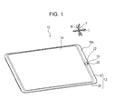
- an electronic device 10 As depicted in FIG. 1 , an electronic device 10 according to the embodiment includes an enclosure 12, a display 14, and a sensor unit 16. Arrows T, L, and W in the drawings represent the thickness, length, and width directions of the electronic device 10 (the enclosure 12), respectively.
- the enclosure 12 has a front case 18 and a rear case 20.
- the front case 18 and rear case 20 are separated from each other in the thickness direction of the enclosure 12.
- the front case 18 is formed in a frame shape, and the display 14, which may be a liquid crystal display for example, is mounted inside the front case 18.
- the front case 18 and rear case 20 contain an internal unit including a control board and a battery, for example, and the display 14 is driven by the control board of the internal unit.
- an opening 22 is formed through the edge 18A in its thickness direction.
- a flange 24 protruding to the inside of the opening 22 is formed.
- the flange 24 is formed around the entire circumference of the opening 22. Due to the presence of the flange 24, the upper portion 22A of the opening 22 on the front surface side of the enclosure 12 has a smaller opening area than a lower portion 22B of the opening 22, which is on the back surface side of the enclosure 12.
- the sensor unit 16 is disposed at a position corresponding to the opening 22 described above.
- the sensor unit 16 has a holder member 26, a switch 28, a fingerprint sensor module 30, and a water sealing member 32 (see also FIG. 2 ).
- the holder member 26 is fixed inside the rear case 20 as depicted in FIG. 2 .
- the holder member 26 has a supporting part 34 and an extending part 36.
- the supporting part 34 is formed in a planar shape and is positioned opposite the above-described opening 22 as illustrated in FIG. 3 .
- the extending part 36 is circularly formed along the circumference of the supporting part 34 and extends from the circumference of the supporting part 34 to the opening 22 side (that is, the upper surface side of the enclosure 12).
- the supporting part 34 has multiple ribs 38 formed thereon. The ribs 38 all extend in the opposite direction to the extending part 36 (that is, to the back surface side of the enclosure 12).
- the switch 28 which is a so-called dome switch, has a substrate 40, a fixed contact 42, and a movable contact 44.
- the switch 28 is disposed in the enclosure 12 opposite the opening 22.
- the substrate 40 is fixed to the supporting part 34 of the holder member 26 with double-sided adhesive tape 46, and the fixed contact 42 and movable contact 44 are fixed to the surface of the substrate 40 on the opening 22 side.
- the movable contact 44 has a bulge on the upper surface side of the enclosure 12, and is positioned on the upper surface side of the enclosure 12 with respect to the fixed contact 42.
- the movable contact 44 is elastic; when it is pressed to the back surface side of the enclosure 12, it comes into contact with the fixed contact 42.
- the fingerprint sensor module 30 which is an example of a key top member, is disposed inside the opening 22.
- the fingerprint sensor module 30 has a sensor portion 48, a substrate 50, and a spacer 52.
- the sensor portion 48 has multiple electrodes arranged in a matrix in the direction orthogonal to the opening direction of the opening 22 (that is, to the axis direction of a central axis line 82).
- the sensor portion 48 is mounted on a surface of the substrate 50.
- the sensor unit 48 outputs a signal representing the positions of valleys and ridges of a fingerprint when a user touches the sensor portion 48 with a finger.
- the substrate 50 of the sensor module 30 is positioned in parallel with the substrate 40 of the switch 28 described above.
- the spacer 52 is fixed with double-sided adhesive tape 54 at a position opposite to the movable contact 44 described above.
- a film-like wiring member 56 is connected as illustrated in FIG. 2 .
- the wiring member 56 is connected with a connector 58 provided in the rear case 20 through the inside of the circular water sealing member 32 discussed later.
- the water sealing member 32 has a wall part reinforcer 60, an arm part reinforcer 62, and a rubber part 64.
- the wall part reinforcer 60 and the arm part reinforcer 62 are both made of sheet metal.
- the rubber part 64 is molded as one piece with the wall part reinforcer 60 and the arm part reinforcer 62 and has a wall part 66 and an arm part 68.
- the wall part 66 extends such that its height direction coincides with the opening direction of the opening 22, and tightly fits on the inner surface of the opening 22, as depicted in FIG. 3 .
- the wall part 66 is circularly formed around the fingerprint sensor module 30.
- the arm part 68 is positioned between the fingerprint sensor module 30 and the switch 28 when seen in the opening direction of the opening 22.
- the arm part 68 extends at an angle from a middle portion of the wall part 66 in its height direction, to the inner side of the opening 22 and to the side of the fingerprint sensor module 30.
- the middle portion of the wall part 66 in its height direction the arm part 68 is connected to a part on the lower end side of the center of the wall part 66 in its height direction.
- An end 68A of the arm part 68 supports the fingerprint sensor module 30 from the switch 28 side (the back surface side of the enclosure 12).
- the arm part 68 is formed around the entire circumference of the wall part 66.
- the wall part reinforcer 60 reinforces the wall part 66, and includes a reinforcer body 70 which extends such that its height direction coincides with the height direction of the wall part 66, and a bent portion 72 formed by bending the reinforcer body 70 at a lower end thereof toward the outer side of the opening 22.
- the reinforcer body 70 and the bent portion 72 are circularly formed in the circumferential direction of the opening 22.
- the reinforcer body 70 is buried in the wall part 66, and the bent portion 72 is exposed (or protrudes) from the lower end of the wall part 66.
- the lower end of the wall part 66 formed on the rubber part 64 and the bent portion 72 are fixed to an end 36A of the extending part 36 with double-sided adhesive tape 74.
- the bent portion 72 is secured between an opening edge 22C of the opening 22 on the side of the extending part 36 (the back surface side of the enclosure 12) and the end 36A of the extending part 36 together with the double-sided adhesive tape 74.
- the arm part reinforcer 62 is a separate piece from the wall part reinforcer 60.
- the arm part reinforcer 62 is formed in a planer shape and disposed such that its thickness direction coincides with the opening direction of the opening 22.
- the arm part reinforcer 62 reinforces the end 68A of the arm part 68.
- the arm part reinforcer 62 is fixed to the underside of the substrate 50 of the fingerprint sensor module 30 with double-sided adhesive tape 76.
- a hole 78 is formed in a center of the arm part reinforcer 62; the water sealing member 32 is circularly formed as a whole (see also FIG. 2 ).
- a connecting portion 68B of the arm part 68 formed between the wall part 66 and the end 68A of the arm part 68 is formed of the rubber of the rubber part 64.
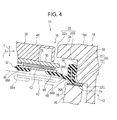
- the fingerprint sensor module 30 presses the switch 28 by causing a flipping motion of the arm part 68 across the virtual center line 80.
- the arm part 68 drawn in solid lines represents the position before the flipping motion
- the arm part 68 drawn in two-dot chain lines represents the position after the flipping motion.
- the above-described opening 22, switch 28, and fingerprint sensor module 30 are coaxially disposed.
- a central axis line 82 through the opening 22, switch 28, and fingerprint sensor module 30 is inclined relative to the thickness direction of the enclosure 12. More specifically, the central axis line 82 is inclined so as to be biased to the center side in the length direction of the enclosure 12 (to the side indicated by arrow C) as it goes from the upper surface of the enclosure 12 to its underside.
- the water sealing member 32 has as its integral parts the wall part 66 for blocking entry of water from the opening 22 and the arm part 68 supporting the fingerprint sensor module 30.
- the wall part 66 tightly fits on the inner surface of the opening 22, and the arm part 68 extends from the wall part 66 to the inner side of the opening 22.
- the size of the enclosure 12 may be reduced compared to a design which positions a water sealing member for blocking entry of water from outside the opening 22, for example.
- a slit may be formed around the opening 22 and a part of the water sealing member may be press-fit into the slit.
- Another design includes, for example, a rubber member for supporting a fingerprint sensor module, a holder member disposed around the rubber member, and an O-ring serving as a water sealing member provided on the periphery of the holder member.
- the electronic device 10 according to the embodiment has the wall part 66 (the water sealing member) and the arm part 68 provided inside the opening 22, hence enabling reduction in the size of the enclosure 12.
- the water sealing member 32 having the wall part 66, includes as its integral part the arm part 68 for supporting the fingerprint sensor module 30.
- the number of parts may be reduced compared with a case where a water sealing member for blocking entry of water and a supporting member for supporting the fingerprint sensor module 30 are separate pieces. This may reduce assembly steps as well as costs.
- water sealing is achieved at two positions: at the double-sided adhesive tape 76 between the arm part reinforcer 62 and the fingerprint sensor module 30, and at the wall part 66. Due to the low number of points of water sealing, waterproofness is more secure. Also, the double-sided adhesive tape 74 fixing the lower end of the wall part 66 and the bent portion 72 to the end 36A of the extending part 36 is positioned inside the water sealing member 32 in the enclosure 12. The double-sided adhesive tape 74 accordingly does not have to serve as a water sealing barrier and the adhesion area of the double-sided adhesive tape 74 thus may be small. This enables further reduction in the size of the enclosure 12.
- the central axis line 82 through the opening 22, switch 28, and fingerprint sensor module 30 is inclined relative to the thickness direction of the enclosure 12.
- the projection area of the opening 22, switch 28, and fingerprint sensor module 30 in the thickness direction of the enclosure 12 may be small, which also enables reduction in the size of the enclosure 12.
- the wall part 66 is reinforced by the wall part reinforcer 60. This helps the wall part 66 tightly fit on the inner surface of the opening 22 with increased stability. Moreover, the bent portion 72 is formed in a lower end of the reinforcer body 70 buried in the wall part 66. This may improve the rigidity of the wall part reinforcer 60 and hence that of the wall part 66, thereby further improving the water sealing ability of the wall part 66.
- the extending part 36 extends from the supporting part 34 to the opening 22 side (that is, the upper surface side of the enclosure 12), and the lower end of the wall part 66 and the bent portion 72 formed in the wall part reinforcer 60 are fixed to the end 36A of the extending part 36. Accordingly, when the fingerprint sensor module 30 is pressed to the back surface side of the enclosure 12, the resulting load may be received by the end 36A of the extending part 36. This may keep the fingerprint sensor module 30 and the water sealing member 32 from dropping to the back surface side of the enclosure 12.
- the bent portion 72 is secured between the opening edge 22C of the opening 22 on the side of the extending part 36 and the end 36A of the extending part 36. This avoids the slipping of the fingerprint sensor module 30 and the water sealing member 32 to the upper surface side of the enclosure 12 as well.
- the arm part 68 flips across the virtual center line 80 which is orthogonal to the opening direction of the opening 22 and passing through the connecting portion between the arm part 68 and the wall part 66.
- the arm part 68 is connected to a middle portion of the wall part 66 in its height direction (more specifically, at a position higher than the lower end of the wall part 66 and lower than the center of the wall part 66 when seen in its height direction).
- the inclination angle of the arm part 68 relative to the direction orthogonal to the opening direction of the opening 22 may be made small, which in turn makes the amount of contraction of the arm part 68 during its flipping motion small. This may decrease the load desired for pressing the fingerprint sensor module 30 and thereby improve the operability of the fingerprint sensor module 30 when it is pressed.
- fingerprint sensor module 30 is used as an example of a key top member in the embodiment, a component other than the fingerprint sensor module 30 may be used as the key top member.
- opening 22 is described as being formed on one edge 18A of the front case 18 seen in the length direction, it may be formed in other positions on the enclosure 12.
- switch 28 is described as a so-called dome switch, it may be other kinds of switch.
- the arm part 68 is described as being connected to a part on the lower end side of the center of the wall part 66 in its height direction as an example of the middle portion of the wall part 66 in the height direction.
- the arm part 68 may be connected to the center of the wall part 66 in its height direction or to a point on the upper end side of the center of the wall part 66 in its height direction.
- wall part reinforcer 60 and arm part reinforcer 62 are described as being made of sheet metal, they may be made of other materials.
Landscapes
- Engineering & Computer Science (AREA)
- Microelectronics & Electronic Packaging (AREA)
- Push-Button Switches (AREA)
- Casings For Electric Apparatus (AREA)
- Image Input (AREA)
- Switch Cases, Indication, And Locking (AREA)
Abstract
Description
- The embodiment discussed herein is related to an electronic device.
- Electronic devices that include an enclosure with an opening formed therein, a switch provided in the enclosure opposite the opening, a key top member disposed inside the opening, and a water sealing member for both supporting the key top member and keeping water from entering through the opening are known.
- Some electronic devices of this type block entry of water from the opening by forming a slit around the opening and press-fitting a part of the water sealing member into the slit.
- Related arts are disclosed in Japanese Laid-open Patent Publication Nos.
2010-108749 2011-204461 - A purpose of the embodiments is for reduceing the size of the enclosure of electronic devices inspite of necessity to reserve an area for forming a slit on the enclosure.
- According to an aspect of the invention, an electronic device includes: an enclosure that has an opening formed therein; a switch disposed in the enclosure opposite the opening; a key top member disposed inside the opening; and a water sealing member that has a wall part which extends such that a height direction of the wall part coincides with an opening direction of the opening and which seals an inner surface of the opening, an arm part which extends from the wall part to the inner side of the opening and supports the key top member, and a wall part reinforcer provided in the wall part.
-
-
FIG. 1 is a perspective view of an electronic device; -
FIG. 2 is an exploded perspective view of the sensor unit and the rear case depicted inFIG. 1 ; -
FIG. 3 is a longitudinal sectional view of the sensor unit and surrounding components depicted inFIG. 1 ; and -
FIG. 4 is an enlarged view of components ofFIG. 3 . - An embodiment of the technique according to the present disclosure will be described.
- As depicted in
FIG. 1 , anelectronic device 10 according to the embodiment includes anenclosure 12, adisplay 14, and asensor unit 16. Arrows T, L, and W in the drawings represent the thickness, length, and width directions of the electronic device 10 (the enclosure 12), respectively. - The
enclosure 12 has afront case 18 and arear case 20. Thefront case 18 andrear case 20 are separated from each other in the thickness direction of theenclosure 12. - The
front case 18 is formed in a frame shape, and thedisplay 14, which may be a liquid crystal display for example, is mounted inside thefront case 18. Thefront case 18 andrear case 20 contain an internal unit including a control board and a battery, for example, and thedisplay 14 is driven by the control board of the internal unit. - As illustrated in
FIG. 3 , on oneedge 18A (an upper edge) of thefront case 18 when seen in the length direction, anopening 22 is formed through theedge 18A in its thickness direction. At anupper portion 22A of the opening 22 on the upper surface side of theenclosure 12, aflange 24 protruding to the inside of theopening 22 is formed. Theflange 24 is formed around the entire circumference of the opening 22. Due to the presence of theflange 24, theupper portion 22A of theopening 22 on the front surface side of theenclosure 12 has a smaller opening area than alower portion 22B of theopening 22, which is on the back surface side of theenclosure 12. - The
sensor unit 16 is disposed at a position corresponding to theopening 22 described above. Thesensor unit 16 has aholder member 26, aswitch 28, afingerprint sensor module 30, and a water sealing member 32 (see alsoFIG. 2 ). - The
holder member 26 is fixed inside therear case 20 as depicted inFIG. 2 . Theholder member 26 has a supportingpart 34 and an extendingpart 36. The supportingpart 34 is formed in a planar shape and is positioned opposite the above-describedopening 22 as illustrated inFIG. 3 . The extendingpart 36 is circularly formed along the circumference of the supportingpart 34 and extends from the circumference of the supportingpart 34 to the opening 22 side (that is, the upper surface side of the enclosure 12). The supportingpart 34 hasmultiple ribs 38 formed thereon. Theribs 38 all extend in the opposite direction to the extending part 36 (that is, to the back surface side of the enclosure 12). - The
switch 28, which is a so-called dome switch, has asubstrate 40, afixed contact 42, and amovable contact 44. Theswitch 28 is disposed in theenclosure 12 opposite theopening 22. Thesubstrate 40 is fixed to the supportingpart 34 of theholder member 26 with double-sidedadhesive tape 46, and the fixedcontact 42 andmovable contact 44 are fixed to the surface of thesubstrate 40 on the opening 22 side. Themovable contact 44 has a bulge on the upper surface side of theenclosure 12, and is positioned on the upper surface side of theenclosure 12 with respect to the fixedcontact 42. Themovable contact 44 is elastic; when it is pressed to the back surface side of theenclosure 12, it comes into contact with the fixedcontact 42. - The
fingerprint sensor module 30, which is an example of a key top member, is disposed inside theopening 22. Thefingerprint sensor module 30 has asensor portion 48, asubstrate 50, and aspacer 52. Thesensor portion 48 has multiple electrodes arranged in a matrix in the direction orthogonal to the opening direction of the opening 22 (that is, to the axis direction of a central axis line 82). Thesensor portion 48 is mounted on a surface of thesubstrate 50. Thesensor unit 48 outputs a signal representing the positions of valleys and ridges of a fingerprint when a user touches thesensor portion 48 with a finger. - The
substrate 50 of thesensor module 30 is positioned in parallel with thesubstrate 40 of theswitch 28 described above. On the underside of thesubstrate 50, thespacer 52 is fixed with double-sidedadhesive tape 54 at a position opposite to themovable contact 44 described above. To thesubstrate 50, a film-like wiring member 56 is connected as illustrated inFIG. 2 . Thewiring member 56 is connected with aconnector 58 provided in therear case 20 through the inside of the circularwater sealing member 32 discussed later. - The
water sealing member 32 has a wall part reinforcer 60, an arm part reinforcer 62, and arubber part 64. The wall part reinforcer 60 and thearm part reinforcer 62 are both made of sheet metal. Therubber part 64 is molded as one piece with the wall part reinforcer 60 and the arm part reinforcer 62 and has awall part 66 and anarm part 68. Thewall part 66 extends such that its height direction coincides with the opening direction of the opening 22, and tightly fits on the inner surface of the opening 22, as depicted inFIG. 3 . Thewall part 66 is circularly formed around thefingerprint sensor module 30. - The
arm part 68 is positioned between thefingerprint sensor module 30 and theswitch 28 when seen in the opening direction of theopening 22. Thearm part 68 extends at an angle from a middle portion of thewall part 66 in its height direction, to the inner side of theopening 22 and to the side of thefingerprint sensor module 30. As an example of the middle portion of thewall part 66 in its height direction, thearm part 68 is connected to a part on the lower end side of the center of thewall part 66 in its height direction. Anend 68A of thearm part 68 supports thefingerprint sensor module 30 from theswitch 28 side (the back surface side of the enclosure 12). Thearm part 68 is formed around the entire circumference of thewall part 66. - The wall part reinforcer 60 reinforces the
wall part 66, and includes areinforcer body 70 which extends such that its height direction coincides with the height direction of thewall part 66, and abent portion 72 formed by bending thereinforcer body 70 at a lower end thereof toward the outer side of theopening 22. Thereinforcer body 70 and thebent portion 72 are circularly formed in the circumferential direction of the opening 22. Thereinforcer body 70 is buried in thewall part 66, and thebent portion 72 is exposed (or protrudes) from the lower end of thewall part 66. The lower end of thewall part 66 formed on therubber part 64 and thebent portion 72 are fixed to anend 36A of the extendingpart 36 with double-sidedadhesive tape 74. Thebent portion 72 is secured between anopening edge 22C of the opening 22 on the side of the extending part 36 (the back surface side of the enclosure 12) and theend 36A of the extendingpart 36 together with the double-sidedadhesive tape 74. - The
arm part reinforcer 62 is a separate piece from the wall part reinforcer 60. Thearm part reinforcer 62 is formed in a planer shape and disposed such that its thickness direction coincides with the opening direction of the opening 22. By being integral with theend 68A of thearm part 68, thearm part reinforcer 62 reinforces theend 68A of thearm part 68. Thearm part reinforcer 62 is fixed to the underside of thesubstrate 50 of thefingerprint sensor module 30 with double-sidedadhesive tape 76. Ahole 78 is formed in a center of thearm part reinforcer 62; thewater sealing member 32 is circularly formed as a whole (see alsoFIG. 2 ). - A connecting
portion 68B of thearm part 68 formed between thewall part 66 and theend 68A of thearm part 68 is formed of the rubber of therubber part 64. As a result, the above-describedfingerprint sensor module 30 is resiliently supported relative to thefront case 18 and also is able to move in the opening direction of theopening 22. When thefingerprint sensor module 30 is pressed by a finger, thespacer 52 pushes down themovable contact 44, which comes into contact with the fixedcontact 42. - When assuming that a line orthogonal to the opening direction of the
opening 22 and passing through the connecting portion between thearm part 68 and thewall part 66 is avirtual center line 80 as illustrated inFIG. 4 , thefingerprint sensor module 30 presses theswitch 28 by causing a flipping motion of thearm part 68 across thevirtual center line 80. InFIG. 4 , thearm part 68 drawn in solid lines represents the position before the flipping motion, while thearm part 68 drawn in two-dot chain lines (imaginary lines) represents the position after the flipping motion. - Also, as illustrated in
FIG. 3 , the above-describedopening 22,switch 28, andfingerprint sensor module 30 are coaxially disposed. Acentral axis line 82 through theopening 22,switch 28, andfingerprint sensor module 30 is inclined relative to the thickness direction of theenclosure 12. More specifically, thecentral axis line 82 is inclined so as to be biased to the center side in the length direction of the enclosure 12 (to the side indicated by arrow C) as it goes from the upper surface of theenclosure 12 to its underside. - Next the operation and effects of the embodiment will be described.
- As discussed in detail above, according to the embodiment, the
water sealing member 32 has as its integral parts thewall part 66 for blocking entry of water from theopening 22 and thearm part 68 supporting thefingerprint sensor module 30. Thewall part 66 tightly fits on the inner surface of theopening 22, and thearm part 68 extends from thewall part 66 to the inner side of theopening 22. Thus, the size of theenclosure 12 may be reduced compared to a design which positions a water sealing member for blocking entry of water from outside theopening 22, for example. - As an example of the design which positions the above-described water sealing member outside the
opening 22, a slit may be formed around theopening 22 and a part of the water sealing member may be press-fit into the slit. Another design includes, for example, a rubber member for supporting a fingerprint sensor module, a holder member disposed around the rubber member, and an O-ring serving as a water sealing member provided on the periphery of the holder member. In contrast to these designs, theelectronic device 10 according to the embodiment has the wall part 66 (the water sealing member) and thearm part 68 provided inside theopening 22, hence enabling reduction in the size of theenclosure 12. - The
water sealing member 32, having thewall part 66, includes as its integral part thearm part 68 for supporting thefingerprint sensor module 30. Thus, the number of parts may be reduced compared with a case where a water sealing member for blocking entry of water and a supporting member for supporting thefingerprint sensor module 30 are separate pieces. This may reduce assembly steps as well as costs. - In the
electronic device 10, water sealing is achieved at two positions: at the double-sidedadhesive tape 76 between thearm part reinforcer 62 and thefingerprint sensor module 30, and at thewall part 66. Due to the low number of points of water sealing, waterproofness is more secure. Also, the double-sidedadhesive tape 74 fixing the lower end of thewall part 66 and thebent portion 72 to theend 36A of the extendingpart 36 is positioned inside thewater sealing member 32 in theenclosure 12. The double-sidedadhesive tape 74 accordingly does not have to serve as a water sealing barrier and the adhesion area of the double-sidedadhesive tape 74 thus may be small. This enables further reduction in the size of theenclosure 12. - The
central axis line 82 through theopening 22,switch 28, andfingerprint sensor module 30 is inclined relative to the thickness direction of theenclosure 12. Thus, the projection area of theopening 22,switch 28, andfingerprint sensor module 30 in the thickness direction of theenclosure 12 may be small, which also enables reduction in the size of theenclosure 12. - Additionally, the
wall part 66 is reinforced by thewall part reinforcer 60. This helps thewall part 66 tightly fit on the inner surface of theopening 22 with increased stability. Moreover, thebent portion 72 is formed in a lower end of thereinforcer body 70 buried in thewall part 66. This may improve the rigidity of thewall part reinforcer 60 and hence that of thewall part 66, thereby further improving the water sealing ability of thewall part 66. - The extending
part 36 extends from the supportingpart 34 to theopening 22 side (that is, the upper surface side of the enclosure 12), and the lower end of thewall part 66 and thebent portion 72 formed in thewall part reinforcer 60 are fixed to theend 36A of the extendingpart 36. Accordingly, when thefingerprint sensor module 30 is pressed to the back surface side of theenclosure 12, the resulting load may be received by theend 36A of the extendingpart 36. This may keep thefingerprint sensor module 30 and thewater sealing member 32 from dropping to the back surface side of theenclosure 12. Thebent portion 72 is secured between the openingedge 22C of theopening 22 on the side of the extendingpart 36 and theend 36A of the extendingpart 36. This avoids the slipping of thefingerprint sensor module 30 and thewater sealing member 32 to the upper surface side of theenclosure 12 as well. - Also, as illustrated in
FIG. 4 , when thefingerprint sensor module 30 is pressed, thearm part 68 flips across thevirtual center line 80 which is orthogonal to the opening direction of theopening 22 and passing through the connecting portion between thearm part 68 and thewall part 66. Thearm part 68 is connected to a middle portion of thewall part 66 in its height direction (more specifically, at a position higher than the lower end of thewall part 66 and lower than the center of thewall part 66 when seen in its height direction). Thus, the inclination angle of thearm part 68 relative to the direction orthogonal to the opening direction of theopening 22 may be made small, which in turn makes the amount of contraction of thearm part 68 during its flipping motion small. This may decrease the load desired for pressing thefingerprint sensor module 30 and thereby improve the operability of thefingerprint sensor module 30 when it is pressed. - Next, variations of the embodiment will be described.
- While the
fingerprint sensor module 30 is used as an example of a key top member in the embodiment, a component other than thefingerprint sensor module 30 may be used as the key top member. - While the
opening 22 is described as being formed on oneedge 18A of thefront case 18 seen in the length direction, it may be formed in other positions on theenclosure 12. - While the
switch 28 is described as a so-called dome switch, it may be other kinds of switch. - The
arm part 68 is described as being connected to a part on the lower end side of the center of thewall part 66 in its height direction as an example of the middle portion of thewall part 66 in the height direction. Alternatively, thearm part 68 may be connected to the center of thewall part 66 in its height direction or to a point on the upper end side of the center of thewall part 66 in its height direction. - While the
wall part reinforcer 60 andarm part reinforcer 62 are described as being made of sheet metal, they may be made of other materials. - While the
electronic device 10 is described as having thedisplay 14, it does not necessarily have thedisplay 14. - Note that the variations above may be practiced in combination as appropriate.
- While an embodiment of the technique according to the present disclosure has been described, it will be appreciated that the above description is not limitative and the technique according to the present disclosure may be practiced with various modifications made thereto without departing from its scope.
- In relation to an aspect of the technique according to the present disclosure described above, the following appendices are further disclosed.
Claims (9)
- An electronic device comprising:an enclosure that has an opening formed therein;a switch disposed in the enclosure opposite the opening;a key top member disposed inside the opening; anda water sealing member that has a wall part which extends such that a height direction of the wall part coincides with an opening direction of the opening and which seals an inner surface of the opening, an arm part which extends from the wall part to the inner side of the opening and supports the key top member, and a wall part reinforcer provided in the wall part.
- The electronic device according to claim 1, wherein
the arm part is positioned between the key top member and the switch, and extends from a height-direction middle portion of the wall part to the inner side of the opening and to the side of the key top member, and
the key top member presses the switch by causing a flipping motion of the arm part across a virtual center line that is orthogonal to the opening direction of the opening and passes through a connecting portion between the arm part and the wall part. - The electronic device according to claim 1, wherein
a central axis line through the opening, the switch, and the key top member is inclined relative to a thickness direction of the enclosure. - The electronic device according to claim 1, further comprising:a holder member that has a supporting part to support the switch, and an extending part which extends from the supporting part to an opening side of the enclosure; whereina lower end of the wall part is fixed to an end of the extending part.
- The electronic device according to claim 4, wherein
the wall part reinforcer has a reinforcer body which extends such that the height direction of the reinforcer body coincides with the height direction of the wall part, and a bent portion formed by bending the reinforcer body at a lower end thereof toward an outer side of the opening, and
the bent portion is secured between an opening edge of the opening on the side of the extending part and the end of the extending part. - The electronic device according to claim 4, wherein
the wall part reinforcer has a reinforcer body which extends such that its height direction coincides with the height direction of the wall part, and a bent portion formed by bending the reinforcer body at a lower end thereof toward an outer side of the opening, and
the bent portion is secured between an opening edge of the opening on the side of the extending part and the end of the extending part. - The electronic device according to claim 1, wherein
the water sealing member is a separate piece from the wall part reinforcer and has an arm part reinforcer provided at an end of the arm part, and
the arm part reinforcer is fixed to the key top member. - The electronic device according to claim 7, wherein the arm part reinforcer is fixed to the key top member with double-sided adhesive tape.
- The electronic device according to any one of claims 1 to 8, wherein the key top member is a fingerprint sensor module.
Applications Claiming Priority (1)
| Application Number | Priority Date | Filing Date | Title |
|---|---|---|---|
| JP2012233243A JP2014086230A (en) | 2012-10-22 | 2012-10-22 | Electronics |
Publications (2)
| Publication Number | Publication Date |
|---|---|
| EP2722860A1 true EP2722860A1 (en) | 2014-04-23 |
| EP2722860B1 EP2722860B1 (en) | 2016-01-06 |
Family
ID=49356328
Family Applications (1)
| Application Number | Title | Priority Date | Filing Date |
|---|---|---|---|
| EP13188964.4A Not-in-force EP2722860B1 (en) | 2012-10-22 | 2013-10-16 | Electronic device |
Country Status (3)
| Country | Link |
|---|---|
| US (2) | US9497874B2 (en) |
| EP (1) | EP2722860B1 (en) |
| JP (1) | JP2014086230A (en) |
Cited By (1)
| Publication number | Priority date | Publication date | Assignee | Title |
|---|---|---|---|---|
| CN107613704A (en) * | 2017-08-28 | 2018-01-19 | 维沃移动通信有限公司 | A kind of fingerprint module and mobile terminal |
Families Citing this family (7)
| Publication number | Priority date | Publication date | Assignee | Title |
|---|---|---|---|---|
| US9729686B2 (en) * | 2013-12-18 | 2017-08-08 | Samsung Electronics Co., Ltd | Electronic device having a circuit board in contact with a case |
| JP6340901B2 (en) * | 2014-05-08 | 2018-06-13 | 富士通株式会社 | Portable electronic device and fingerprint sensor unit |
| BR112018017285A2 (en) * | 2016-04-05 | 2019-01-15 | Huawei Tech Co Ltd | terminal and method for mounting the terminal collection module |
| CN107241468B (en) * | 2017-05-12 | 2020-08-18 | Oppo广东移动通信有限公司 | Display device and mobile terminal |
| JP2020201559A (en) * | 2019-06-06 | 2020-12-17 | レノボ・シンガポール・プライベート・リミテッド | Keyboard device and electronic apparatus |
| CN111031728B (en) * | 2019-12-26 | 2021-04-20 | Oppo广东移动通信有限公司 | Electronic device, assembly method, and disassembly method |
| USD997107S1 (en) * | 2020-12-04 | 2023-08-29 | Zoox, Inc. | Door interface system having an animated visual indicator |
Citations (5)
| Publication number | Priority date | Publication date | Assignee | Title |
|---|---|---|---|---|
| JP2004273208A (en) * | 2003-03-06 | 2004-09-30 | Mitsubishi Electric Corp | Push button switch and method of manufacturing the same |
| JP2010108749A (en) | 2008-10-30 | 2010-05-13 | Kyocera Corp | Portable electronic apparatus |
| JP2011204461A (en) | 2010-03-25 | 2011-10-13 | Kyocera Corp | Electronic apparatus |
| WO2012011236A1 (en) * | 2010-07-23 | 2012-01-26 | シャープ株式会社 | Push-button switch structure and electronic apparatus provided with same |
| US20120227251A1 (en) * | 2010-07-23 | 2012-09-13 | Shin-Etsu Polymer Co., Ltd. | Manufacturing method of push-button switch |
Family Cites Families (5)
| Publication number | Priority date | Publication date | Assignee | Title |
|---|---|---|---|---|
| US7795553B2 (en) | 2006-09-11 | 2010-09-14 | Apple Inc. | Hybrid button |
| JP5100591B2 (en) * | 2008-09-25 | 2012-12-19 | 株式会社ホンダロック | Push-button switch |
| JP2010238029A (en) | 2009-03-31 | 2010-10-21 | Omron Corp | Information input device |
| US8446264B2 (en) * | 2010-07-21 | 2013-05-21 | Research In Motion Limited | Portable electronic device having a waterproof keypad |
| US20120279844A1 (en) * | 2011-05-03 | 2012-11-08 | David Wang | Multifunctional Touch Switch Apparatus for Bathroom |
-
2012
- 2012-10-22 JP JP2012233243A patent/JP2014086230A/en not_active Withdrawn
-
2013
- 2013-10-14 US US14/053,337 patent/US9497874B2/en not_active Expired - Fee Related
- 2013-10-16 EP EP13188964.4A patent/EP2722860B1/en not_active Not-in-force
-
2016
- 2016-01-19 US US15/000,451 patent/US20160143172A1/en not_active Abandoned
Patent Citations (5)
| Publication number | Priority date | Publication date | Assignee | Title |
|---|---|---|---|---|
| JP2004273208A (en) * | 2003-03-06 | 2004-09-30 | Mitsubishi Electric Corp | Push button switch and method of manufacturing the same |
| JP2010108749A (en) | 2008-10-30 | 2010-05-13 | Kyocera Corp | Portable electronic apparatus |
| JP2011204461A (en) | 2010-03-25 | 2011-10-13 | Kyocera Corp | Electronic apparatus |
| WO2012011236A1 (en) * | 2010-07-23 | 2012-01-26 | シャープ株式会社 | Push-button switch structure and electronic apparatus provided with same |
| US20120227251A1 (en) * | 2010-07-23 | 2012-09-13 | Shin-Etsu Polymer Co., Ltd. | Manufacturing method of push-button switch |
Cited By (1)
| Publication number | Priority date | Publication date | Assignee | Title |
|---|---|---|---|---|
| CN107613704A (en) * | 2017-08-28 | 2018-01-19 | 维沃移动通信有限公司 | A kind of fingerprint module and mobile terminal |
Also Published As
| Publication number | Publication date |
|---|---|
| US20140111920A1 (en) | 2014-04-24 |
| JP2014086230A (en) | 2014-05-12 |
| EP2722860B1 (en) | 2016-01-06 |
| US9497874B2 (en) | 2016-11-15 |
| US20160143172A1 (en) | 2016-05-19 |
Similar Documents
| Publication | Publication Date | Title |
|---|---|---|
| EP2722860B1 (en) | Electronic device | |
| US9137918B2 (en) | Electronic apparatus and method for assembling the same | |
| US8174846B2 (en) | Electronic device | |
| TW201229845A (en) | Touch control device and an electronic apparatus using the same | |
| US10379634B2 (en) | Information processing apparatus and base member | |
| JP6089296B2 (en) | Electronics | |
| JP6403089B2 (en) | Board connection structure and electronic equipment | |
| US20140118960A1 (en) | Electronic apparatus and method for assembling the same | |
| JP2010192243A (en) | Switch device | |
| US9417659B2 (en) | Electronic apparatus | |
| JP6104600B2 (en) | Electronics | |
| WO2014006756A1 (en) | Switch unit and electronic device | |
| US20140376166A1 (en) | Front member for capacitive display screen panel of electronic devices | |
| JP6691301B2 (en) | Electronic equipment and housing | |
| US20110051361A1 (en) | Electronic device | |
| US9013639B2 (en) | Electronic apparatus having a module protection buffer | |
| JP2013247655A (en) | Electronic apparatus | |
| US9089045B2 (en) | Display apparatus | |
| US9578146B2 (en) | Electronic assembly and electronic apparatus | |
| JP6241497B2 (en) | Electronic equipment | |
| JP6125264B2 (en) | Electronic device with flexible lead board | |
| CN102902304A (en) | Electronic device with false touch prevention function | |
| JP4929376B2 (en) | Electronics | |
| US20150170851A1 (en) | Electronic apparatus and circuit module | |
| JP2016076191A (en) | Electronic device and touch panel unit |
Legal Events
| Date | Code | Title | Description |
|---|---|---|---|
| PUAI | Public reference made under article 153(3) epc to a published international application that has entered the european phase |
Free format text: ORIGINAL CODE: 0009012 |
|
| AK | Designated contracting states |
Kind code of ref document: A1 Designated state(s): AL AT BE BG CH CY CZ DE DK EE ES FI FR GB GR HR HU IE IS IT LI LT LU LV MC MK MT NL NO PL PT RO RS SE SI SK SM TR |
|
| AX | Request for extension of the european patent |
Extension state: BA ME |
|
| 17P | Request for examination filed |
Effective date: 20140611 |
|
| RBV | Designated contracting states (corrected) |
Designated state(s): AL AT BE BG CH CY CZ DE DK EE ES FI FR GB GR HR HU IE IS IT LI LT LU LV MC MK MT NL NO PL PT RO RS SE SI SK SM TR |
|
| RIC1 | Information provided on ipc code assigned before grant |
Ipc: H05K 5/06 20060101ALI20150529BHEP Ipc: H01H 13/86 20060101ALI20150529BHEP Ipc: H01H 13/06 20060101AFI20150529BHEP |
|
| GRAP | Despatch of communication of intention to grant a patent |
Free format text: ORIGINAL CODE: EPIDOSNIGR1 |
|
| INTG | Intention to grant announced |
Effective date: 20150715 |
|
| GRAS | Grant fee paid |
Free format text: ORIGINAL CODE: EPIDOSNIGR3 |
|
| GRAA | (expected) grant |
Free format text: ORIGINAL CODE: 0009210 |
|
| AK | Designated contracting states |
Kind code of ref document: B1 Designated state(s): AL AT BE BG CH CY CZ DE DK EE ES FI FR GB GR HR HU IE IS IT LI LT LU LV MC MK MT NL NO PL PT RO RS SE SI SK SM TR |
|
| REG | Reference to a national code |
Ref country code: GB Ref legal event code: FG4D |
|
| REG | Reference to a national code |
Ref country code: CH Ref legal event code: EP |
|
| REG | Reference to a national code |
Ref country code: IE Ref legal event code: FG4D |
|
| REG | Reference to a national code |
Ref country code: AT Ref legal event code: REF Ref document number: 769482 Country of ref document: AT Kind code of ref document: T Effective date: 20160215 |
|
| REG | Reference to a national code |
Ref country code: DE Ref legal event code: R096 Ref document number: 602013004461 Country of ref document: DE |
|
| REG | Reference to a national code |
Ref country code: LT Ref legal event code: MG4D |
|
| REG | Reference to a national code |
Ref country code: NL Ref legal event code: MP Effective date: 20160106 |
|
| REG | Reference to a national code |
Ref country code: AT Ref legal event code: MK05 Ref document number: 769482 Country of ref document: AT Kind code of ref document: T Effective date: 20160106 |
|
| PG25 | Lapsed in a contracting state [announced via postgrant information from national office to epo] |
Ref country code: NL Free format text: LAPSE BECAUSE OF FAILURE TO SUBMIT A TRANSLATION OF THE DESCRIPTION OR TO PAY THE FEE WITHIN THE PRESCRIBED TIME-LIMIT Effective date: 20160106 |
|
| PG25 | Lapsed in a contracting state [announced via postgrant information from national office to epo] |
Ref country code: NO Free format text: LAPSE BECAUSE OF FAILURE TO SUBMIT A TRANSLATION OF THE DESCRIPTION OR TO PAY THE FEE WITHIN THE PRESCRIBED TIME-LIMIT Effective date: 20160406 Ref country code: FI Free format text: LAPSE BECAUSE OF FAILURE TO SUBMIT A TRANSLATION OF THE DESCRIPTION OR TO PAY THE FEE WITHIN THE PRESCRIBED TIME-LIMIT Effective date: 20160106 Ref country code: HR Free format text: LAPSE BECAUSE OF FAILURE TO SUBMIT A TRANSLATION OF THE DESCRIPTION OR TO PAY THE FEE WITHIN THE PRESCRIBED TIME-LIMIT Effective date: 20160106 Ref country code: ES Free format text: LAPSE BECAUSE OF FAILURE TO SUBMIT A TRANSLATION OF THE DESCRIPTION OR TO PAY THE FEE WITHIN THE PRESCRIBED TIME-LIMIT Effective date: 20160106 Ref country code: GR Free format text: LAPSE BECAUSE OF FAILURE TO SUBMIT A TRANSLATION OF THE DESCRIPTION OR TO PAY THE FEE WITHIN THE PRESCRIBED TIME-LIMIT Effective date: 20160407 Ref country code: IT Free format text: LAPSE BECAUSE OF FAILURE TO SUBMIT A TRANSLATION OF THE DESCRIPTION OR TO PAY THE FEE WITHIN THE PRESCRIBED TIME-LIMIT Effective date: 20160106 |
|
| PG25 | Lapsed in a contracting state [announced via postgrant information from national office to epo] |
Ref country code: IS Free format text: LAPSE BECAUSE OF FAILURE TO SUBMIT A TRANSLATION OF THE DESCRIPTION OR TO PAY THE FEE WITHIN THE PRESCRIBED TIME-LIMIT Effective date: 20160506 Ref country code: LV Free format text: LAPSE BECAUSE OF FAILURE TO SUBMIT A TRANSLATION OF THE DESCRIPTION OR TO PAY THE FEE WITHIN THE PRESCRIBED TIME-LIMIT Effective date: 20160106 Ref country code: PT Free format text: LAPSE BECAUSE OF FAILURE TO SUBMIT A TRANSLATION OF THE DESCRIPTION OR TO PAY THE FEE WITHIN THE PRESCRIBED TIME-LIMIT Effective date: 20160506 Ref country code: PL Free format text: LAPSE BECAUSE OF FAILURE TO SUBMIT A TRANSLATION OF THE DESCRIPTION OR TO PAY THE FEE WITHIN THE PRESCRIBED TIME-LIMIT Effective date: 20160106 Ref country code: SE Free format text: LAPSE BECAUSE OF FAILURE TO SUBMIT A TRANSLATION OF THE DESCRIPTION OR TO PAY THE FEE WITHIN THE PRESCRIBED TIME-LIMIT Effective date: 20160106 Ref country code: LT Free format text: LAPSE BECAUSE OF FAILURE TO SUBMIT A TRANSLATION OF THE DESCRIPTION OR TO PAY THE FEE WITHIN THE PRESCRIBED TIME-LIMIT Effective date: 20160106 Ref country code: AT Free format text: LAPSE BECAUSE OF FAILURE TO SUBMIT A TRANSLATION OF THE DESCRIPTION OR TO PAY THE FEE WITHIN THE PRESCRIBED TIME-LIMIT Effective date: 20160106 Ref country code: RS Free format text: LAPSE BECAUSE OF FAILURE TO SUBMIT A TRANSLATION OF THE DESCRIPTION OR TO PAY THE FEE WITHIN THE PRESCRIBED TIME-LIMIT Effective date: 20160106 |
|
| REG | Reference to a national code |
Ref country code: DE Ref legal event code: R097 Ref document number: 602013004461 Country of ref document: DE |
|
| PG25 | Lapsed in a contracting state [announced via postgrant information from national office to epo] |
Ref country code: EE Free format text: LAPSE BECAUSE OF FAILURE TO SUBMIT A TRANSLATION OF THE DESCRIPTION OR TO PAY THE FEE WITHIN THE PRESCRIBED TIME-LIMIT Effective date: 20160106 Ref country code: DK Free format text: LAPSE BECAUSE OF FAILURE TO SUBMIT A TRANSLATION OF THE DESCRIPTION OR TO PAY THE FEE WITHIN THE PRESCRIBED TIME-LIMIT Effective date: 20160106 |
|
| PLBE | No opposition filed within time limit |
Free format text: ORIGINAL CODE: 0009261 |
|
| STAA | Information on the status of an ep patent application or granted ep patent |
Free format text: STATUS: NO OPPOSITION FILED WITHIN TIME LIMIT |
|
| PG25 | Lapsed in a contracting state [announced via postgrant information from national office to epo] |
Ref country code: SM Free format text: LAPSE BECAUSE OF FAILURE TO SUBMIT A TRANSLATION OF THE DESCRIPTION OR TO PAY THE FEE WITHIN THE PRESCRIBED TIME-LIMIT Effective date: 20160106 Ref country code: RO Free format text: LAPSE BECAUSE OF FAILURE TO SUBMIT A TRANSLATION OF THE DESCRIPTION OR TO PAY THE FEE WITHIN THE PRESCRIBED TIME-LIMIT Effective date: 20160106 Ref country code: CZ Free format text: LAPSE BECAUSE OF FAILURE TO SUBMIT A TRANSLATION OF THE DESCRIPTION OR TO PAY THE FEE WITHIN THE PRESCRIBED TIME-LIMIT Effective date: 20160106 Ref country code: SK Free format text: LAPSE BECAUSE OF FAILURE TO SUBMIT A TRANSLATION OF THE DESCRIPTION OR TO PAY THE FEE WITHIN THE PRESCRIBED TIME-LIMIT Effective date: 20160106 |
|
| 26N | No opposition filed |
Effective date: 20161007 |
|
| PG25 | Lapsed in a contracting state [announced via postgrant information from national office to epo] |
Ref country code: BE Free format text: LAPSE BECAUSE OF FAILURE TO SUBMIT A TRANSLATION OF THE DESCRIPTION OR TO PAY THE FEE WITHIN THE PRESCRIBED TIME-LIMIT Effective date: 20160106 |
|
| PG25 | Lapsed in a contracting state [announced via postgrant information from national office to epo] |
Ref country code: BG Free format text: LAPSE BECAUSE OF FAILURE TO SUBMIT A TRANSLATION OF THE DESCRIPTION OR TO PAY THE FEE WITHIN THE PRESCRIBED TIME-LIMIT Effective date: 20160406 Ref country code: SI Free format text: LAPSE BECAUSE OF FAILURE TO SUBMIT A TRANSLATION OF THE DESCRIPTION OR TO PAY THE FEE WITHIN THE PRESCRIBED TIME-LIMIT Effective date: 20160106 |
|
| REG | Reference to a national code |
Ref country code: DE Ref legal event code: R119 Ref document number: 602013004461 Country of ref document: DE |
|
| REG | Reference to a national code |
Ref country code: CH Ref legal event code: PL |
|
| REG | Reference to a national code |
Ref country code: IE Ref legal event code: MM4A |
|
| REG | Reference to a national code |
Ref country code: FR Ref legal event code: ST Effective date: 20170630 |
|
| PG25 | Lapsed in a contracting state [announced via postgrant information from national office to epo] |
Ref country code: CH Free format text: LAPSE BECAUSE OF NON-PAYMENT OF DUE FEES Effective date: 20161031 Ref country code: LI Free format text: LAPSE BECAUSE OF NON-PAYMENT OF DUE FEES Effective date: 20161031 Ref country code: FR Free format text: LAPSE BECAUSE OF NON-PAYMENT OF DUE FEES Effective date: 20161102 Ref country code: DE Free format text: LAPSE BECAUSE OF NON-PAYMENT OF DUE FEES Effective date: 20170503 |
|
| PG25 | Lapsed in a contracting state [announced via postgrant information from national office to epo] |
Ref country code: LU Free format text: LAPSE BECAUSE OF NON-PAYMENT OF DUE FEES Effective date: 20161016 |
|
| PG25 | Lapsed in a contracting state [announced via postgrant information from national office to epo] |
Ref country code: IE Free format text: LAPSE BECAUSE OF NON-PAYMENT OF DUE FEES Effective date: 20161016 |
|
| PG25 | Lapsed in a contracting state [announced via postgrant information from national office to epo] |
Ref country code: CY Free format text: LAPSE BECAUSE OF FAILURE TO SUBMIT A TRANSLATION OF THE DESCRIPTION OR TO PAY THE FEE WITHIN THE PRESCRIBED TIME-LIMIT Effective date: 20160106 Ref country code: HU Free format text: LAPSE BECAUSE OF FAILURE TO SUBMIT A TRANSLATION OF THE DESCRIPTION OR TO PAY THE FEE WITHIN THE PRESCRIBED TIME-LIMIT; INVALID AB INITIO Effective date: 20131016 |
|
| GBPC | Gb: european patent ceased through non-payment of renewal fee |
Effective date: 20171016 |
|
| PG25 | Lapsed in a contracting state [announced via postgrant information from national office to epo] |
Ref country code: MC Free format text: LAPSE BECAUSE OF FAILURE TO SUBMIT A TRANSLATION OF THE DESCRIPTION OR TO PAY THE FEE WITHIN THE PRESCRIBED TIME-LIMIT Effective date: 20160106 Ref country code: MK Free format text: LAPSE BECAUSE OF FAILURE TO SUBMIT A TRANSLATION OF THE DESCRIPTION OR TO PAY THE FEE WITHIN THE PRESCRIBED TIME-LIMIT Effective date: 20160106 Ref country code: MT Free format text: LAPSE BECAUSE OF NON-PAYMENT OF DUE FEES Effective date: 20161031 |
|
| PG25 | Lapsed in a contracting state [announced via postgrant information from national office to epo] |
Ref country code: GB Free format text: LAPSE BECAUSE OF NON-PAYMENT OF DUE FEES Effective date: 20171016 |
|
| PG25 | Lapsed in a contracting state [announced via postgrant information from national office to epo] |
Ref country code: TR Free format text: LAPSE BECAUSE OF FAILURE TO SUBMIT A TRANSLATION OF THE DESCRIPTION OR TO PAY THE FEE WITHIN THE PRESCRIBED TIME-LIMIT Effective date: 20160106 Ref country code: AL Free format text: LAPSE BECAUSE OF FAILURE TO SUBMIT A TRANSLATION OF THE DESCRIPTION OR TO PAY THE FEE WITHIN THE PRESCRIBED TIME-LIMIT Effective date: 20160106 |