EP2722716A2 - Image forming apparatus and method of controlling the same - Google Patents
Image forming apparatus and method of controlling the same Download PDFInfo
- Publication number
- EP2722716A2 EP2722716A2 EP13188382.9A EP13188382A EP2722716A2 EP 2722716 A2 EP2722716 A2 EP 2722716A2 EP 13188382 A EP13188382 A EP 13188382A EP 2722716 A2 EP2722716 A2 EP 2722716A2
- Authority
- EP
- European Patent Office
- Prior art keywords
- transfer roller
- roller
- toner
- image forming
- forming apparatus
- Prior art date
- Legal status (The legal status is an assumption and is not a legal conclusion. Google has not performed a legal analysis and makes no representation as to the accuracy of the status listed.)
- Granted
Links
Images




Classifications
-
- G—PHYSICS
- G03—PHOTOGRAPHY; CINEMATOGRAPHY; ANALOGOUS TECHNIQUES USING WAVES OTHER THAN OPTICAL WAVES; ELECTROGRAPHY; HOLOGRAPHY
- G03G—ELECTROGRAPHY; ELECTROPHOTOGRAPHY; MAGNETOGRAPHY
- G03G15/00—Apparatus for electrographic processes using a charge pattern
- G03G15/14—Apparatus for electrographic processes using a charge pattern for transferring a pattern to a second base
- G03G15/16—Apparatus for electrographic processes using a charge pattern for transferring a pattern to a second base of a toner pattern, e.g. a powder pattern, e.g. magnetic transfer
- G03G15/1665—Apparatus for electrographic processes using a charge pattern for transferring a pattern to a second base of a toner pattern, e.g. a powder pattern, e.g. magnetic transfer by introducing the second base in the nip formed by the recording member and at least one transfer member, e.g. in combination with bias or heat
- G03G15/167—Apparatus for electrographic processes using a charge pattern for transferring a pattern to a second base of a toner pattern, e.g. a powder pattern, e.g. magnetic transfer by introducing the second base in the nip formed by the recording member and at least one transfer member, e.g. in combination with bias or heat at least one of the recording member or the transfer member being rotatable during the transfer
- G03G15/1685—Structure, details of the transfer member, e.g. chemical composition
-
- G—PHYSICS
- G03—PHOTOGRAPHY; CINEMATOGRAPHY; ANALOGOUS TECHNIQUES USING WAVES OTHER THAN OPTICAL WAVES; ELECTROGRAPHY; HOLOGRAPHY
- G03G—ELECTROGRAPHY; ELECTROPHOTOGRAPHY; MAGNETOGRAPHY
- G03G15/00—Apparatus for electrographic processes using a charge pattern
- G03G15/14—Apparatus for electrographic processes using a charge pattern for transferring a pattern to a second base
- G03G15/16—Apparatus for electrographic processes using a charge pattern for transferring a pattern to a second base of a toner pattern, e.g. a powder pattern, e.g. magnetic transfer
Definitions
- the present invention relates to an image forming apparatus including a transfer roller to charge paper such that a developing agent is adsorbed to the paper and a method of controlling the same.
- An electrophotographic type image forming apparatus uses a transfer member to feed a toner image generated by a developing member to recording media, i.e. paper.
- a corona mode and a transfer roller mode are known as transfer modes.
- the transfer roller mode is mainly used in consideration of miniaturization of image forming apparatuses and ozone generation in the corona mode.
- transfer bias is applied to the transfer member, i.e. the transfer roller, to generate a transfer field and transfer is electrostatically performed according to the transfer field.
- transfer roller mode paper may be contaminated by the transfer roller if the transfer roller contains contaminants before the paper contacts the transfer roller. For this reason, the transfer roller may be cleaned.
- a first method of cleaning the transfer roller is to provide a cleaning member to clean the transfer roller. Specifically, a cleaning blade or a cleaning roller is disposed at the rear of the transfer roller to clean the transfer roller.
- this method needs additional devices and is thus not suitable for miniaturization and reduction of cost.
- the cleaning member may increase torque of the transfer roller and thus negatively affect jitter.
- a second method of cleaning the transfer roller is an electrostatic cleaning method of applying transfer bias to the transfer roller to clean the transfer roller.
- cleaning bias is applied to the transfer roller to remove toner from the transfer roller.
- cleaning bias having the same polarity as toner and cleaning bias having a polarity opposite to that of the toner are alternately applied to the transfer roller.
- toner charged with positive (+) and negative (-) polarities may be removed from the transfer roller.
- the transfer roller is partially contaminated, the transfer roller is not uniformly charged with the result that image quality may be deteriorated and cleaning may not be completely achieved.
- an image forming apparatus and a method of controlling the same wherein a plurality of cells formed at the surface of a transfer roller is filled with a developing agent to initialize the transfer roller, thereby suppressing contamination and electrical non-uniformity of the transfer roller.
- a method of controlling an image forming apparatus includes determining whether a transfer roller mounted in the image forming apparatus is a new one and, upon determining that the transfer roller is a new one, feeding a developing agent to a surface of the transfer roller and filling a plurality of cells formed at the surface of the transfer roller with the developing agent to initialize the transfer roller.
- the method may further include determining that the transfer roller is a new one when a count value of use time of the transfer roller is reset.
- the method may further include controlling a photoconductor such that the developing agent is fed to the surface of the transfer roller via the photoconductor.
- An outer layer of the transfer roller may be formed of a foam material.
- the method may further include cleaning the initialized transfer roller without additional application of the developing agent.
- a method of controlling an image forming apparatus includes determining whether a transfer roller initialization command has been generated and, upon determining that the transfer roller initialization command has been generated, feeding a developing agent to a surface of the transfer roller and filling a plurality of cells formed at the surface of the transfer roller with the developing agent to initialize the transfer roller.
- the transfer roller initialization command may be generated by user input.
- An outer layer of the transfer roller may be formed of a foam material.
- the method may further include cleaning the initialized transfer roller without additional application of the developing agent.
- an image forming apparatus includes a transfer roller and a controller to control the transfer roller such that a developing agent is fed to a surface of the transfer roller and a plurality of cells formed at the surface of the transfer roller is filled with the developing agent to initialize the transfer roller upon determining that the transfer roller is a new one.
- the image forming apparatus may further include a counter to count use time of the transfer roller, wherein the controller may determine that the transfer roller is a new one when a count value of the counter is reset.
- the controller may control a photoconductor such that the developing agent is fed to the surface of the transfer roller via the photoconductor.
- An outer layer of the transfer roller may be formed of a foam material.
- the controller may control the initialized transfer roller to be cleaned without additional application of the developing agent.
- an image forming apparatus includes a transfer roller and a controller to control the transfer roller such that a developing agent is fed to a surface of the transfer roller and a plurality of cells formed at the surface of the transfer roller is filled with the developing agent to initialize the transfer roller upon determining that a transfer roller initialization command has been generated.
- the transfer roller initialization command may be generated by user input.
- An outer layer of the transfer roller may be formed of a foam material.
- the controller may control the initialized transfer roller to be cleaned without additional application of the developing agent.
- FIG. 1 is a view showing an image forming apparatus 100 according to an embodiment.
- the image forming apparatus 100 of FIG. 1 is an electrophotographic type monochromatic image forming apparatus to form only a monochromatic image.
- the image forming apparatus 100 includes a body case 104, a paper supply unit 106, a photoconductor 108, a light scanning unit 110, a developing cartridge 112, a transfer roller 114, and a fusing unit 116.
- the body case 104 forms the external appearance of the image forming apparatus 100.
- the paper supply unit 106 is provided in the body case 104. Paper 102 is loaded in the paper supply unit 106.
- the photoconductor 108 is formed in the shape of a cylindrical drum extending a predetermined length corresponding to the width of paper 102.
- the photoconductor 108 is charged with fixed polar potential by a charging roller 118, which will hereinafter be described.
- An electrostatic latent image due to potential difference is formed on the photoconductor 108, the outer circumference of which is uniformly charged, by beams scanned by the light scanning unit 110.
- Toner 122 is supplied to the electrostatic latent image by a developing roller 120, which will hereinafter be described.
- An image due to the toner 122 is transferred to paper 102 passing through a space between the photoconductor 108 and the transfer roller 114.
- the light scanning unit 110 scans beams corresponding to image data to be formed on paper 102 to the photoconductor 108 such that an electrostatic latent image is formed on the photoconductor 108.
- the light scanning unit 110 may include a laser scanning unit using a laser diode as a light source. Various other light sources may replace the laser scanning unit.
- the developing cartridge 112 supplies a developing agent, i.e. toner 122, to the electrostatic latent image of the photoconductor 108.
- the developing cartridge 112 includes a cartridge case 132, a charging roller 118, a developing roller 120, a toner storage unit 124, a hopper 126, a supply roller 128, and a regulation blade 130.
- the charging roller 118 and the photoconductor 108 are rotated in contact.
- the charging roller 118 charges the surface of the photoconductor 108 with a predetermined potential value.
- the developing roller 120 supplies toner 122 to the electrostatic latent image formed on the photoconductor 108.
- the toner storage unit 124 is provided in the cartridge case 132 to store toner 122.
- the hopper 126 is provided in the toner storage unit 124.
- the supply roller 128 is provided in the toner storage unit 124 to supply toner 122 to the developing roller 120.
- the regulation blade 130 extends from the toner storage unit 124 so as to contact the developing roller 120.
- the charging roller 118 is provided in the cartridge case 132 to be rotated in contact with the photoconductor 108. The charging roller 118, to which charging bias has been applied, charges the outer circumference of the photoconductor 108 with a predetermined potential value.
- the developing roller 120 to which developing bias has been applied, is rotated in contact with the supply roller 128.
- the toner 122 from the supply roller 128 is attached to the developing roller 120 due to potential difference between the developing roller 120 and the supply roller 128.
- the developing roller 120 to which the toner 122 has been attached, is rotated in contact with the photoconductor 108.
- the toner storage unit 124 is formed in the cartridge case 132 as a space to store toner 122.
- the toner storage unit 124 is opened at one side thereof at which the developing roller 120 is provided. Consequently, stored toner 122 is supplied to the developing roller 120 by the supply roller 128.
- At least one hopper 126 is mounted in the toner storage unit 124.
- the hopper 126 is rotated in the toner storage unit 124 to transfer toner 122 to the supply roller 128.
- the hopper 126 agitates the toner 122 to prevent solidification of the toner 122 and improve mobility of the toner 122.
- the hopper 126 agitates the toner 122 such that the toner 122 is charged with a predetermined potential value.
- the supply roller 128 is provided at one side of the toner storage unit 124 so as to be rotated in contact with the developing roller 120.
- the supply roller 128 supplies the toner 122, transferred by the hopper 126, to the developing roller 120.
- the supply roller 128 is rotated in the direction opposite to the rotational direction of the developing roller 120.
- the toner 122 passing through a space between the supply roller 128 and the developing roller 120 is charged with a predetermined potential value.
- a proper amount of toner 122 is attached to the developing roller 120.
- the regulation blade 130 extends from one end of the cartridge case 132 to contact the developing roller 120 at predetermined pressing force.
- the regulation blade 130 secures uniformity in amount of toner 122 supplied from the supply roller 128 and attached to the developing roller 120, i.e. mass of toner 122 per unit area of the developing roller 120 M/A (g/cm2).
- the regulation blade 130 charges the toner 122 attached to the developing roller 120 with a predetermined potential value.
- the regulation blade 130 may be configured to include a conductive material and to have a predetermined potential value upon receiving power.
- toner 122 may be classified as two component type toner, one magnetic component type toner, or one nonmagnetic component type toner.
- one nonmagnetic component type toner 122 is used.
- the one nonmagnetic component type toner 122 contains resin to adjust basic quantity of charge or to decide fusing temperature.
- the resin occupies 90% or more of the contents of the toner 122.
- Carbon to decide polarity and color, an external additive, such as wax, to improve mobility, and silica to improve hydrophobicity and mobility are added as other constituents.
- the toner 122 exhibits mobility in a dry state due to the constituents.
- the toner 122 is charged with a predetermined potential value due to friction.
- the supply roller 128, the developing roller 120, the regulation blade 130, the charging roller 118, the photoconductor 108, and the transfer roller 114 are biased such that voltage difference occurs therebetween.
- the supply roller 128, the developing roller, 120, the regulation blade 130, the charging roller 118, the photoconductor 108, and the transfer roller 114 may be independently biased.
- a Zener diode may be individually provided for the supply roller 128, the developing roller 120, the regulation blade 130, the charging roller 118, the photoconductor 108, and the transfer roller 114 such that uniform voltage difference is maintained therebetween.
- a variable control (for example, PWM control) type voltage supply device may be individually provided for the supply roller 128, the developing roller 120, the regulation blade 130, the charging roller 118, the photoconductor 108, and the transfer roller 114 to variably control the amplitudes of voltages applied to the supply roller 128, the developing roller, 120, the regulation blade 130, the charging roller 118, the photoconductor 108, and the transfer roller 114 using the surroundings and lifespan information of the image forming apparatus 100.
- the amplitudes of voltages applied to the supply roller 128, the developing roller 120, the regulation blade 130, the charging roller 118, the photoconductor 108, and the transfer roller 114 are variably controlled to properly adjust the concentration of toner.
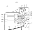
- FIG. 2 is a view showing an image forming apparatus 200 according to an embodiment.
- the image forming apparatus 200 of FIG. 2 is an electrophotographic type color image forming apparatus to form a color image.
- the image forming apparatus 200 includes four developing cartridges 210Y, 210M, 210C, and 210K, four light scanning units 225Y, 225M, 225C, and 225K, an image transfer unit 230, and a fusing unit 250, all of which are provided in a body case 201. Also, the image forming apparatus 200 further includes a paper supply unit 227, in which paper 202 is loaded, a pickup roller 228 to pick up the paper 202 from the paper supply unit 227 one by one, a feeding roller 229 to feed the picked up paper 202, and a paper discharge roller 253 to the paper 202, on which an image has been printed, from the body case 201.
- a paper supply unit 227 in which paper 202 is loaded
- a pickup roller 228 to pick up the paper 202 from the paper supply unit 227 one by one
- a feeding roller 229 to feed the picked up paper 202
- a paper discharge roller 253 to the paper 202, on which an image has been printed, from the
- the developing cartridges 210Y, 210M, 210C, and 210K are replaced with new ones.
- the developing cartridges 210Y, 210M, 210C, and 210K contains different color toners, such as yellow (Y), magenta (M), cyan (C), and black (K) toners, respectively, to print a color image.
- a transfer belt 235 is disposed horizontally such that the used developing cartridges 210Y, 210M, 210C, and 210K may be replaced with new ones.
- the four light scanning units 225Y, 225M, 225C, and 225K correspond to the developing cartridges 210Y, 210M, 210C, and 210K, respectively.
- the light scanning units 225Y, 225M, 225C, and 225K scan yellow (Y), magenta (M), cyan (C), and black (K) lights corresponding to image information to photoconductors 245Y, 245M, 245C, and 245K mounted in the respective developing cartridges 210Y, 210M, 210C, and 210K.
- a laser scanning unit (LSU) using a laser diode as a light source may be adopted for each of the light scanning units 225Y, 225M, 225C, and 225K.
- the photoconductors 245Y, 245M, 245C, and 245K and developing rollers 215Y, 215M, 215C, and 215K are provided in the developing cartridges 210Y, 210M, 210C, and 210K, respectively. A portion of the outer circumference of each of the photoconductors 245Y, 245M, 245C, and 245K contacts the transfer belt 235 to transfer a toner image.
- the developing cartridges 210Y, 210M, 210C, and 210K include charging rollers 219Y, 219M, 219C, and 219K, respectively. Charging bias is applied to the charging rollers 219Y, 219M, 219C, and 219K to charge the outer circumferences of the photoconductors 245Y, 245M, 245C, and 245K with uniform potential.
- the developing rollers 215 ⁇ Y, 215M, 215C, and 215K supply toner, attached to the outer circumferences thereof, to the photoconductors 245Y, 245M, 245C, and 245K, respectively.
- Developing bias is applied to the developing rollers 215Y, 215M, 215C, and 215K to supply toner to the photoconductors 245Y, 245M, 245C, and 245K.
- supply rollers to supply toner to the developing rollers 215Y, 215M, 215C, and 215K
- regulation blades to regulate the amount of toner attached to the developing rollers 215Y, 215M, 215C, and 215K
- agitators to feed toner to the supply roller (not shown) while agitating the toner are further provided in the developing cartridges 210Y, 210M, 210C, and 210K, respectively.
- the image transfer unit 230 includes the four photoconductors 245Y, 245M, 245C, and 245K.
- the image transfer unit 230 further includes a driving roller, i.e. a first roller 231, a driven roller, i.e. a second roller 232, disposed under the first roller 231 in parallel, a transfer belt 235 to move in circulation while being wound on the first roller 231 and the second roller 232, and four transfer rollers 240Y, 240M, 240C, and 240K disposed between the first roller 231 and the second roller 232.
- the image transfer unit 230 further includes auxiliary support rollers 233 and 234 to auxiliarily support the transfer belt 235.
- the four transfer rollers 240Y, 240M, 240C, and 240K are disposed opposite to the four photoconductors 245Y, 245M, 245C, and 245K while the transfer belt 235 is disposed between the transfer rollers 240Y, 240M, 240C, and 240K and the photoconductors 245Y, 245M, 245C, and 245K.
- the transfer rollers 240Y, 240M, 240C, and 240K charge the back side (a side opposite to a recording side on which an image is formed) of paper 202 passing through a space between the photoconductors 245Y, 245M, 245C, and 245K and the transfer rollers 240Y, 240M, 240C, and 240K with a polarity opposite to that of toner such that the toner from the surfaces of the photoconductors 245Y, 245M, 245C, and 245K is adsorbed to the front side of the paper 202.
- the fusing unit 250 fuses the toner on the front side of the paper 202. To this end, transfer bias is applied to the transfer rollers 240Y, 240M, 240C, and 240K.
- force to rotate the photoconductors 245Y, 245M, 245C, and 245K is greater than force to move the transfer belt 235.
- a drive gear (not shown) to transmit driving force is connected to each of the photoconductors 245Y, 245M, 245C, and 245K, and therefore, force to rotate the photoconductors 245Y, 245M, 245C, and 245K is large.
- the transfer belt 235 is moved only by the driving force of the first roller 231, and the other rollers 232, 233, 234, 240Y, 240M, 240C, and 240K are driven according to movement of the transfer belt 235, and therefore, force to move the transfer belt 235 is small.
- FIG. 3 is a view showing structures of the photoconductor and the transfer roller of the monochromatic image forming apparatus of FIG. 1 .
- the transfer roller 114 of the image forming apparatus 100 is rotated in contact with the photoconductor 108 to transfer an image due to toner 122 to paper 102. That is, the transfer roller 114 charges the back side 102b (a side opposite to a recording side on which an image is formed) of paper 102 passing through the space between the photoconductor 108 and the transfer roller 114 with a polarity opposite to that of toner such that the toner 122 from the surface of the photoconductor 108 is adsorbed to the recording side 102a of the paper 102.
- transfer bias is applied to the transfer roller 114.
- the transfer rollers 240Y, 240M, 240C, and 240K of the color image forming apparatus 200 shown in FIG. 2 are operated in the same manner as what was described above.
- the color image forming apparatus 200 includes the four transfer rollers 240Y, 240M, 240C, and 240K and photoconductors 245Y, 245M, 245C, and 245K corresponding to the number of colors of the developing agent, i.e. the toner, and a registration process for each color is carried out.
- the outer layer of the transfer roller 114 is formed of a foam material, such as foam sponge. Consequently, a plurality of cells 302 is provided at the surface of the transfer roller 114. Contaminants, such as paper powder and waste toner (particularly, non-polar toner with an external additive removed therefrom), are introduced into the cells 302 to contaminate the back side 102b of the paper 102.
- transfer bias is not uniformly applied to the transfer roller 114 due to non-uniformity of the contaminants in the cells 302.
- Non-uniform application of bias to the transfer roller 114 may cause the paper 102 to be non-uniformly charged when the paper 102 is charged with a polarity opposite to that of the toner, and therefore, quality of an image may be deteriorated.
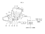
- FIG. 4 is a view showing a control system of the image forming apparatus according to an embodiment.
- the control system shown in FIG. 4 is applied to the monochromatic image forming apparatus 100 of FIG. 1 .
- the control system shown in FIG. 4 may also be applied to the color image forming apparatus 200 of FIG. 2 .
- a controller 402 controls overall operation of the image forming apparatus 100.
- the controller 402 has a counter 404 mounted therein.
- the counter 404 counts use time of the transfer roller 114.
- a user or a service engineer resets a count value of the counter 404.
- the counter 404 may be provided outside the controller 402.
- the controller 402 may receive another user input. This user input may include a transfer roller initialization command generated through an input unit of the image forming apparatus 100 for a user (or a service engineer) to forcibly perform initialization of the transfer roller 114.
- the controller 402 applies bias to the developing cartridge 112, the photoconductor 108, and the transfer roller 114 through a high voltage power supply 406 to perform electrical charge, development, and transfer. Also, the controller 402 controls the developing cartridge 112, the photoconductor 108, and the transfer roller 114 such that the transfer roller 114 is initialized to suppress contamination and electrical non-uniformity of the transfer roller 114.
- the electrical non-uniformity of the transfer roller 114 may include a case in which the transfer roller 114 has locally different surface resistance values.
- the surface resistance of the region of the transfer roller 114 having cells 302 fully filled with contaminants or waste toner is relatively high, and the surface resistance of the region of the transfer roller 114 having cells 302 not filled with contaminants or waste toner or partially filled with contaminants or waste toner is relatively low.
- Initialization of the transfer roller 114 is to pre-fill the cells 302 formed at the outer surface of the transfer roller 114, the outer layer of which is formed of foam sponge, with a developing agent, i.e. toner.
- toner 122 is supplied and attached to the entire surface of the photoconductor 108 and contact between the photoconductor 108 and the transfer roller 114 is performed without introduction of paper 102 between the photoconductor 108 and the transfer roller 114 such that the toner 122 is attached to the surface of the transfer roller 114. Also, this process is continuously performed for a predetermined time such that all of the cells 302 of the transfer roller 114 are uniformly filled with the toner 122. Through initialization, introduction of contaminants into the cells 302 of the transfer roller 114 may be suppressed and electrical non-uniformity of the transfer roller 114, which may occur when only some of the cells 302 are filled with contaminants, may be solved.
- Initialization of the transfer roller 114 may be performed with respect to the transfer roller 114 in use or a new transfer roller 114.
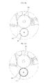
- FIGS. 5A and 5B are views showing an initialization state of a transfer roller according to an embodiment.
- FIGS. 5A and 5B show an initialization state of a new transfer roller 114.
- a new transfer roller 114 is a transfer roller 114 which has not been used after production, such as a transfer roller 114 mounted in a new image forming apparatus 100 or a transfer roller 114 replacing a used transfer roller 114 of a sold image forming apparatus 100.
- FIG. 5A is a view showing a state before a new transfer roller 114 is initialized. As shown in FIG. 5A , contaminants or waste toner is not present in a plurality of cells 302 formed at the surface of the transfer roller 114. If the transfer roller 114 is used as it is, contaminants or waste toner may be introduced into the cells 302. Through initialization of the transfer roller 114, therefore, the cells 302 are filled with toner.
- FIG. 5B is a view showing a state after the transfer roller 114 is initialized.
- the cells 302 formed at the surface of the transfer roller 114 are filled with toner through initialization of the transfer roller 114.
- contaminants or waste toner is not introduced into the cells 302 .
- the transfer roller 114 may exhibit uniform electrical characteristics.
- FIGS. 6A and 6B are views showing an initialization state of a transfer roller according to an embodiment.
- FIGS. 6A and 6B show an initialization state of a used transfer roller 114.
- a used transfer roller 114 is a transfer roller 114 which has already been mounted in the image forming apparatus 100.
- FIG. 6A is a view showing a state before a used transfer roller 114 is initialized.
- contaminants or waste toner is present in some or all cells 302 formed at the surface of the transfer roller 114 through use of the image forming apparatus 100 before initialization.
- paper 102 or the photoconductor 108 may be contaminated by the contaminants in the cells 302 of the transfer roller 114.
- electric characteristics of the transfer roller 114 may become non-uniform. Through initialization of the transfer roller 114, therefore, the cells 302 are filled with toner.
- FIG. 6B is a view showing a state after the transfer roller 114 is initialized.
- the cells 302 formed at the surface of the transfer roller 114 are filled with toner through initialization of the transfer roller 114.
- contaminants or waste toner is not introduced into the cells 302.
- the transfer roller 114 may exhibit uniform electrical characteristics.
- FIG. 7 is a view showing a method of controlling the image forming apparatus according to an embodiment.
- the control method of FIG. 7 is used to initialize the new transfer roller 114 shown in FIGS. 5A and 5B .
- the controller 402 when the image forming apparatus 100 is turned on, power is supplied to the image forming apparatus 100 and the image forming apparatus 100 is ready to operate through warming-up (702).
- a counter reset signal is input to the controller 402 in this state (YES of 704), the controller 402 resets a count value of the counter 404 in response to the counter reset signal.
- the counter reset signal is generated by a user (or a service engineer) through the input unit of the image forming apparatus 100. In a case in which the transfer roller 114 is replaced with a new one, the counter reset signal is generated to initialize a count value of a use period (or lifespan) of the transfer roller 114.
- the controller 402 determines that the transfer roller 114 has been replaced with a new one, resets a count value of the counter 404, and controls the transfer roller 114 to be initialized (706). That is, in order to initialize the transfer roller 114, toner 122 is supplied and attached to the entire surface of the photoconductor 108 and contact between the photoconductor 108 and the transfer roller 114 is performed without introduction of paper 102 between the photoconductor 108 and the transfer roller 114 such that the toner 122 is attached to the surface of the transfer roller 114, under the control of the controller 402. Also, this process is continuously performed for a predetermined time such that all of the cells 302 of the transfer roller 114 are uniformly filled with the toner 122.
- the controller 402 may perform cleaning with respect to the initialized transfer roller 114 (708). Cleaning may not be performed immediately after initialization of the transfer roller 114. That is, cleaning may be selectively performed as needed. Cleaning may be periodically performed after one initialization of the transfer roller 114. Alternatively, a predetermined number of cleaning operations may be performed after one initialization of the transfer roller 114, and the initialization and cleaning operations may be periodically repeated. Cleaning of the transfer roller 114 is a process of alternately applying positive (+) bias and negative (-) bias to the transfer roller 114 such that electric energy is supplied to the transfer roller 114 to remove contaminants or residual toner from the surface of the transfer roller 114.
- Cleaning of the transfer roller 114 may be performed using a symmetric application method of alternately applying positive (+) bias and negative (-) bias to the transfer roller 114 in the same period or an asymmetric application method of alternately applying positive (+) bias and negative (-) bias to the transfer roller 114 in different periods.
- FIG. 8 is a view showing a method of controlling the image forming apparatus according to an embodiment.
- the control method of FIG. 8 is used to initialize the used transfer roller 114 shown in FIGS. 6A and 6B .
- the controller 402 controls the transfer roller 114 to be initialized in response to the initialization command (806).
- the initialization command is generated by a user (or a service engineer) through the input unit of the image forming apparatus 100 to forcibly initialize the transfer roller 114 even in a state in which the transfer roller 114 has not been replaced with a new one.
- Forcible initialization of the transfer roller 114 according to the initialization command may be performed in a case in which it is determined that initialization of the transfer roller 114 is necessary regardless of replacement of the transfer roller 114 or in a case in which it is determined that initialization of the transfer roller 114 is necessary in an image forming apparatus which is not configured to automatically initialize transfer roller 114 in response to reset of the counter 404.
- toner 122 is supplied and attached to the entire surface of the photoconductor 108 and contact between the photoconductor 108 and the transfer roller 114 is performed without introduction of paper 102 between the photoconductor 108 and the transfer roller 114 such that the toner 122 is attached to the surface of the transfer roller 114, under the control of the controller 402. Also, this process is continuously performed for a predetermined time such that all of the cells 302 of the transfer roller 114 are uniformly filled with the toner 122.
- the controller 402 may perform cleaning with respect to the initialized transfer roller 114 (808). Cleaning may not be performed immediately after initialization of the transfer roller 114. That is, cleaning may be selectively performed as needed. Cleaning may be periodically performed after one initialization of the transfer roller 114. Alternatively, a predetermined number of cleaning operations may be performed after one initialization of the transfer roller 114, and the initialization and cleaning operations may be periodically repeated. Cleaning of the transfer roller 114 is a process of alternately applying positive (+) bias and negative (-) bias to the transfer roller 114 such that electric energy is supplied to the transfer roller 114 to remove contaminants or residual toner from the surface of the transfer roller 114.
- Cleaning of the transfer roller 114 may be performed using a symmetric application method of alternately applying positive (+) bias and negative (-) bias to the transfer roller 114 in the same period or an asymmetric application method of alternately applying positive (+) bias and negative (-) bias to the transfer roller 114 in different periods.
- FIGS. 9A and 9B are views showing a method of checking a clean state of the transfer roller according to an embodiment after initialization of the transfer roller.
- FIG. 9A shows a state in which a front end 902 of paper 102 is inserted into the fusing unit 116 and a rear end 904 of the paper 102 has not yet passed through the space between the photoconductor 108 and the transfer roller 114. At this time, the paper 102 is advanced in a direction indicated by an arrow in a state in which the paper 102 is curled due to rotational speed difference between the fusing unit 116 and the transfer roller 114, thus having no tension.
- FIG. 9C shows a contamination state of the back side of the rear end 904 of the paper 102 before initialization of the transfer roller 114
- FIG. 9D shows a contamination state of the back side of the rear end 904 of the paper 102 after initialization of the transfer roller 114.
- the back side of the rear end 904 of the paper 102 after initialization of the transfer roller 114 is less contaminated than the back side of the rear end 904 of the paper 102 before initialization of the transfer roller 114.
- initialization of the transfer roller is performed to fill the cells formed at the surface of the transfer roller with toner, thereby suppressing contamination and electrical non-uniformity of the transfer roller and thus providing the following effects.
- the cells are prevented from being filled with contaminants through initialization to fill the cells formed at the surface of the transfer roller with toner.
- the transfer roller exhibits uniform electrical characteristics (for example, surface resistance) through initialization to fill the cells formed at the surface of the transfer roller with toner.
- transfer bias may be uniformly applied to the transfer roller, and cleaning bias may be uniformly applied to the transfer roller, thereby improving a cleaning effect.
- Initialization of a new transfer roller provides higher effects. As needed, initialization may also be performed with respect to a transfer roller in use.
Landscapes
- Physics & Mathematics (AREA)
- General Physics & Mathematics (AREA)
- Electrostatic Charge, Transfer And Separation In Electrography (AREA)
Abstract

Description
- The present invention relates to an image forming apparatus including a transfer roller to charge paper such that a developing agent is adsorbed to the paper and a method of controlling the same.
- An electrophotographic type image forming apparatus uses a transfer member to feed a toner image generated by a developing member to recording media, i.e. paper. A corona mode and a transfer roller mode are known as transfer modes. The transfer roller mode is mainly used in consideration of miniaturization of image forming apparatuses and ozone generation in the corona mode.
- In the transfer roller mode, transfer bias is applied to the transfer member, i.e. the transfer roller, to generate a transfer field and transfer is electrostatically performed according to the transfer field. In the transfer roller mode, however, paper may be contaminated by the transfer roller if the transfer roller contains contaminants before the paper contacts the transfer roller. For this reason, the transfer roller may be cleaned.
- A first method of cleaning the transfer roller is to provide a cleaning member to clean the transfer roller. Specifically, a cleaning blade or a cleaning roller is disposed at the rear of the transfer roller to clean the transfer roller. However, this method needs additional devices and is thus not suitable for miniaturization and reduction of cost.
- Furthermore, the cleaning member may increase torque of the transfer roller and thus negatively affect jitter.
- A second method of cleaning the transfer roller is an electrostatic cleaning method of applying transfer bias to the transfer roller to clean the transfer roller. After or before transfer of a toner image, cleaning bias is applied to the transfer roller to remove toner from the transfer roller. Specifically, cleaning bias having the same polarity as toner and cleaning bias having a polarity opposite to that of the toner are alternately applied to the transfer roller. As a result, toner charged with positive (+) and negative (-) polarities may be removed from the transfer roller.
- When the transfer roller is cleaned in the transfer bias mode, uncharged paper powder or non-polar toner with an external additive removed therefrom is not removed.
- Furthermore, if the transfer roller is partially contaminated, the transfer roller is not uniformly charged with the result that image quality may be deteriorated and cleaning may not be completely achieved.
- In an aspect of one or more embodiments, there is provided an image forming apparatus and a method of controlling the same wherein a plurality of cells formed at the surface of a transfer roller is filled with a developing agent to initialize the transfer roller, thereby suppressing contamination and electrical non-uniformity of the transfer roller.
- In an aspect of one or more embodiments, there is provided a method of controlling an image forming apparatus includes determining whether a transfer roller mounted in the image forming apparatus is a new one and, upon determining that the transfer roller is a new one, feeding a developing agent to a surface of the transfer roller and filling a plurality of cells formed at the surface of the transfer roller with the developing agent to initialize the transfer roller.
- The method may further include determining that the transfer roller is a new one when a count value of use time of the transfer roller is reset.
- The method may further include controlling a photoconductor such that the developing agent is fed to the surface of the transfer roller via the photoconductor.
- An outer layer of the transfer roller may be formed of a foam material.
- The method may further include cleaning the initialized transfer roller without additional application of the developing agent.
- In an aspect of one or more embodiments, there is provided a method of controlling an image forming apparatus includes determining whether a transfer roller initialization command has been generated and, upon determining that the transfer roller initialization command has been generated, feeding a developing agent to a surface of the transfer roller and filling a plurality of cells formed at the surface of the transfer roller with the developing agent to initialize the transfer roller.
- The transfer roller initialization command may be generated by user input.
- An outer layer of the transfer roller may be formed of a foam material.
- The method may further include cleaning the initialized transfer roller without additional application of the developing agent.
- In an aspect of one or more embodiments, there is provided an image forming apparatus includes a transfer roller and a controller to control the transfer roller such that a developing agent is fed to a surface of the transfer roller and a plurality of cells formed at the surface of the transfer roller is filled with the developing agent to initialize the transfer roller upon determining that the transfer roller is a new one.
- The image forming apparatus may further include a counter to count use time of the transfer roller, wherein the controller may determine that the transfer roller is a new one when a count value of the counter is reset.
- The controller may control a photoconductor such that the developing agent is fed to the surface of the transfer roller via the photoconductor.
- An outer layer of the transfer roller may be formed of a foam material.
- The controller may control the initialized transfer roller to be cleaned without additional application of the developing agent.
- In accordance with an aspect of one or more embodiments, there is provided an image forming apparatus includes a transfer roller and a controller to control the transfer roller such that a developing agent is fed to a surface of the transfer roller and a plurality of cells formed at the surface of the transfer roller is filled with the developing agent to initialize the transfer roller upon determining that a transfer roller initialization command has been generated.
- The transfer roller initialization command may be generated by user input.
- An outer layer of the transfer roller may be formed of a foam material.
- The controller may control the initialized transfer roller to be cleaned without additional application of the developing agent.
- These and/or other aspects will become apparent and more readily appreciated from the following description of embodiments, taken in conjunction with the accompanying drawings in which:
-
FIG. 1 is a view showing an image forming apparatus according to an embodiment; -
FIG. 2 is a view showing an image forming apparatus according to an embodiment; -
FIG. 3 is a view showing structures of a photoconductor and a transfer roller of the monochromatic image forming apparatus ofFIG. 1 ; -
FIG. 4 is a view showing a control system of the image forming apparatus according to an embodiment; -
FIGS. 5A and 5B are views showing an initialization state of a transfer roller according to an embodiment; -
FIGS. 6A and 6B are views showing an initialization state of a transfer roller according to an embodiment; -
FIG. 7 is a view showing a method of controlling the image forming apparatus according to an embodiment; -
FIG. 8 is a view showing a method of controlling the image forming apparatus according to an embodiment; and -
FIGS. 9A through 9D are views showing a method of checking a clean state of the transfer roller according to an embodiment after initialization state of the transfer roller. - Reference will now be made in detail to embodiments, examples of which are illustrated in the accompanying drawings, wherein like reference numerals refer to like elements throughout.
-
FIG. 1 is a view showing animage forming apparatus 100 according to an embodiment. - In particular, the
image forming apparatus 100 ofFIG. 1 is an electrophotographic type monochromatic image forming apparatus to form only a monochromatic image. As shown inFIG. 1 , theimage forming apparatus 100 includes abody case 104, apaper supply unit 106, aphotoconductor 108, alight scanning unit 110, a developingcartridge 112, atransfer roller 114, and afusing unit 116. - The
body case 104 forms the external appearance of theimage forming apparatus 100. Thepaper supply unit 106 is provided in thebody case 104.Paper 102 is loaded in thepaper supply unit 106. - The
photoconductor 108 is formed in the shape of a cylindrical drum extending a predetermined length corresponding to the width ofpaper 102. Thephotoconductor 108 is charged with fixed polar potential by acharging roller 118, which will hereinafter be described. An electrostatic latent image due to potential difference is formed on thephotoconductor 108, the outer circumference of which is uniformly charged, by beams scanned by thelight scanning unit 110.Toner 122 is supplied to the electrostatic latent image by a developingroller 120, which will hereinafter be described. An image due to thetoner 122 is transferred topaper 102 passing through a space between thephotoconductor 108 and thetransfer roller 114. - The
light scanning unit 110 scans beams corresponding to image data to be formed onpaper 102 to thephotoconductor 108 such that an electrostatic latent image is formed on thephotoconductor 108. Thelight scanning unit 110 may include a laser scanning unit using a laser diode as a light source. Various other light sources may replace the laser scanning unit. - The developing
cartridge 112 supplies a developing agent, i.e.toner 122, to the electrostatic latent image of thephotoconductor 108. The developingcartridge 112 includes acartridge case 132, a chargingroller 118, a developingroller 120, atoner storage unit 124, ahopper 126, asupply roller 128, and aregulation blade 130. The chargingroller 118 and thephotoconductor 108 are rotated in contact. The chargingroller 118 charges the surface of thephotoconductor 108 with a predetermined potential value. The developingroller 120supplies toner 122 to the electrostatic latent image formed on thephotoconductor 108. Thetoner storage unit 124 is provided in thecartridge case 132 tostore toner 122. Thehopper 126 is provided in thetoner storage unit 124. Thesupply roller 128 is provided in thetoner storage unit 124 to supplytoner 122 to the developingroller 120. Theregulation blade 130 extends from thetoner storage unit 124 so as to contact the developingroller 120. The chargingroller 118 is provided in thecartridge case 132 to be rotated in contact with thephotoconductor 108. The chargingroller 118, to which charging bias has been applied, charges the outer circumference of thephotoconductor 108 with a predetermined potential value. When beams from thelight scanning unit 110 are scanned to thephotoconductor 108 charged with the predetermined potential value by the chargingroller 118, potential values of points of thephotoconductor 108 to which the beams have been scanned are changed due to optical conduction characteristics of thephotoconductor 108. As a result, potential difference occurs between the points of thephotoconductor 108 to which the beams have been scanned and points of thephotoconductor 108 to which the beams have not been scanned. Consequently, an electrostatic latent image due to potential difference is formed on thephotoconductor 108. The developingroller 120 is mounted adjacent to thetoner storage unit 124 and is rotated in the direction opposite to the rotational direction of thephotoconductor 108. The developingroller 120, to which developing bias has been applied, is rotated in contact with thesupply roller 128. Thetoner 122 from thesupply roller 128 is attached to the developingroller 120 due to potential difference between the developingroller 120 and thesupply roller 128. The developingroller 120, to which thetoner 122 has been attached, is rotated in contact with thephotoconductor 108. As a result, thetoner 122 is supplied to the electrostatic latent image of thephotoconductor 108. Thetoner storage unit 124 is formed in thecartridge case 132 as a space to storetoner 122. Thetoner storage unit 124 is opened at one side thereof at which the developingroller 120 is provided. Consequently, storedtoner 122 is supplied to the developingroller 120 by thesupply roller 128. At least onehopper 126 is mounted in thetoner storage unit 124. Thehopper 126 is rotated in thetoner storage unit 124 to transfertoner 122 to thesupply roller 128. Also, thehopper 126 agitates thetoner 122 to prevent solidification of thetoner 122 and improve mobility of thetoner 122. In addition, thehopper 126 agitates thetoner 122 such that thetoner 122 is charged with a predetermined potential value. Thesupply roller 128 is provided at one side of thetoner storage unit 124 so as to be rotated in contact with the developingroller 120. Thesupply roller 128 supplies thetoner 122, transferred by thehopper 126, to the developingroller 120. Thesupply roller 128 is rotated in the direction opposite to the rotational direction of the developingroller 120. As a result, thetoner 122 passing through a space between thesupply roller 128 and the developingroller 120 is charged with a predetermined potential value. At the same time, a proper amount oftoner 122 is attached to the developingroller 120. Theregulation blade 130 extends from one end of thecartridge case 132 to contact the developingroller 120 at predetermined pressing force. As a result, theregulation blade 130 secures uniformity in amount oftoner 122 supplied from thesupply roller 128 and attached to the developingroller 120, i.e. mass oftoner 122 per unit area of the developing roller 120 M/A (g/cm2). Also, theregulation blade 130 charges thetoner 122 attached to the developingroller 120 with a predetermined potential value. To this end, theregulation blade 130 may be configured to include a conductive material and to have a predetermined potential value upon receiving power. - Based on developing type of the
image forming apparatus 100,toner 122 may be classified as two component type toner, one magnetic component type toner, or one nonmagnetic component type toner. In this embodiment, one nonmagneticcomponent type toner 122 is used. The one nonmagneticcomponent type toner 122 contains resin to adjust basic quantity of charge or to decide fusing temperature. The resin occupies 90% or more of the contents of thetoner 122. Carbon to decide polarity and color, an external additive, such as wax, to improve mobility, and silica to improve hydrophobicity and mobility are added as other constituents. Thetoner 122 exhibits mobility in a dry state due to the constituents. In addition, thetoner 122 is charged with a predetermined potential value due to friction. - The
supply roller 128, the developingroller 120, theregulation blade 130, the chargingroller 118, thephotoconductor 108, and thetransfer roller 114 are biased such that voltage difference occurs therebetween. Thesupply roller 128, the developing roller, 120, theregulation blade 130, the chargingroller 118, thephotoconductor 108, and thetransfer roller 114 may be independently biased. Alternatively, a Zener diode may be individually provided for thesupply roller 128, the developingroller 120, theregulation blade 130, the chargingroller 118, thephotoconductor 108, and thetransfer roller 114 such that uniform voltage difference is maintained therebetween. Also, a variable control (for example, PWM control) type voltage supply device may be individually provided for thesupply roller 128, the developingroller 120, theregulation blade 130, the chargingroller 118, thephotoconductor 108, and thetransfer roller 114 to variably control the amplitudes of voltages applied to thesupply roller 128, the developing roller, 120, theregulation blade 130, the chargingroller 118, thephotoconductor 108, and thetransfer roller 114 using the surroundings and lifespan information of theimage forming apparatus 100. The amplitudes of voltages applied to thesupply roller 128, the developingroller 120, theregulation blade 130, the chargingroller 118, thephotoconductor 108, and thetransfer roller 114 are variably controlled to properly adjust the concentration of toner. Proper adjustment in concentration of toner is directly related to quality of an image formed on paper. Only when proper concentration of toner is maintained at the entire image forming area of the paper, high-quality image may be obtained. To this end, the amplitudes of voltages applied to thesupply roller 128, the developingroller 120, theregulation blade 130, the chargingroller 118, thephotoconductor 108, and thetransfer roller 114 are variably controlled. -
FIG. 2 is a view showing animage forming apparatus 200 according to an embodiment. In particular, theimage forming apparatus 200 ofFIG. 2 is an electrophotographic type color image forming apparatus to form a color image. - As shown in
FIG. 2 , theimage forming apparatus 200 includes four developingcartridges light scanning units image transfer unit 230, and afusing unit 250, all of which are provided in abody case 201. Also, theimage forming apparatus 200 further includes apaper supply unit 227, in whichpaper 202 is loaded, apickup roller 228 to pick up thepaper 202 from thepaper supply unit 227 one by one, a feedingroller 229 to feed the picked uppaper 202, and apaper discharge roller 253 to thepaper 202, on which an image has been printed, from thebody case 201. - When a developing agent, i.e. toner, is consumed, the developing
cartridges cartridges - When a
door 204 provided at one side of thebody case 201 is opened, atransfer belt 235 is disposed horizontally such that the used developingcartridges - In this embodiment, the four
light scanning units cartridges light scanning units cartridges light scanning units - The
photoconductors rollers cartridges transfer belt 235 to transfer a toner image. - Also, the developing
cartridges rollers rollers - The developing rollers 215\Y, 215M, 215C, and 215K supply toner, attached to the outer circumferences thereof, to the
photoconductors rollers photoconductors rollers rollers cartridges - The
image transfer unit 230 includes the fourphotoconductors image transfer unit 230 further includes a driving roller, i.e. afirst roller 231, a driven roller, i.e. asecond roller 232, disposed under thefirst roller 231 in parallel, atransfer belt 235 to move in circulation while being wound on thefirst roller 231 and thesecond roller 232, and fourtransfer rollers first roller 231 and thesecond roller 232. Also, theimage transfer unit 230 further includesauxiliary support rollers transfer belt 235. The fourtransfer rollers photoconductors transfer belt 235 is disposed between thetransfer rollers photoconductors transfer rollers paper 202 passing through a space between thephotoconductors transfer rollers paper 202. Thefusing unit 250 fuses the toner on the front side of thepaper 202. To this end, transfer bias is applied to thetransfer rollers - Meanwhile, in the
image forming apparatus 200, force to rotate thephotoconductors transfer belt 235. A drive gear (not shown) to transmit driving force is connected to each of the photoconductors 245Y, 245M, 245C, and 245K, and therefore, force to rotate thephotoconductors transfer belt 235 is moved only by the driving force of thefirst roller 231, and theother rollers transfer belt 235, and therefore, force to move thetransfer belt 235 is small. -
FIG. 3 is a view showing structures of the photoconductor and the transfer roller of the monochromatic image forming apparatus ofFIG. 1 . As shown inFIG. 3 , thetransfer roller 114 of theimage forming apparatus 100 is rotated in contact with thephotoconductor 108 to transfer an image due totoner 122 topaper 102. That is, thetransfer roller 114 charges theback side 102b (a side opposite to a recording side on which an image is formed) ofpaper 102 passing through the space between the photoconductor 108 and thetransfer roller 114 with a polarity opposite to that of toner such that thetoner 122 from the surface of thephotoconductor 108 is adsorbed to therecording side 102a of thepaper 102. To this end, transfer bias is applied to thetransfer roller 114. Thepaper 102, to therecording side 102a of which thetoner 122 has been adsorbed, passes through thefusing unit 116 ofFIG. 1 . At this time, thetoner 102 is fused on thepaper 102 by thefusing unit 116. - The
transfer rollers image forming apparatus 200 shown inFIG. 2 are operated in the same manner as what was described above. - However, the color
image forming apparatus 200 includes the fourtransfer rollers photoconductors - Referring back to
FIG. 3 , the outer layer of thetransfer roller 114 is formed of a foam material, such as foam sponge. Consequently, a plurality ofcells 302 is provided at the surface of thetransfer roller 114. Contaminants, such as paper powder and waste toner (particularly, non-polar toner with an external additive removed therefrom), are introduced into thecells 302 to contaminate theback side 102b of thepaper 102. - Particularly if some
cells 302 are filled with contaminants, somecells 302 are not filled with contaminants, and somecells 302 are partially filled with contaminants, transfer bias is not uniformly applied to thetransfer roller 114 due to non-uniformity of the contaminants in thecells 302. Non-uniform application of bias to thetransfer roller 114 may cause thepaper 102 to be non-uniformly charged when thepaper 102 is charged with a polarity opposite to that of the toner, and therefore, quality of an image may be deteriorated. -
FIG. 4 is a view showing a control system of the image forming apparatus according to an embodiment. The control system shown inFIG. 4 is applied to the monochromaticimage forming apparatus 100 ofFIG. 1 . However, the control system shown inFIG. 4 may also be applied to the colorimage forming apparatus 200 ofFIG. 2 . - As shown in
FIG. 4 , a controller 402 controls overall operation of theimage forming apparatus 100. The controller 402 has a counter 404 mounted therein. The counter 404 counts use time of thetransfer roller 114. When anew transfer roller 114 is mounted, a user (or a service engineer) resets a count value of the counter 404. The counter 404 may be provided outside the controller 402. Also, the controller 402 may receive another user input. This user input may include a transfer roller initialization command generated through an input unit of theimage forming apparatus 100 for a user (or a service engineer) to forcibly perform initialization of thetransfer roller 114. - The controller 402 applies bias to the developing
cartridge 112, thephotoconductor 108, and thetransfer roller 114 through a high voltage power supply 406 to perform electrical charge, development, and transfer. Also, the controller 402 controls the developingcartridge 112, thephotoconductor 108, and thetransfer roller 114 such that thetransfer roller 114 is initialized to suppress contamination and electrical non-uniformity of thetransfer roller 114. The electrical non-uniformity of thetransfer roller 114 may include a case in which thetransfer roller 114 has locally different surface resistance values. That is, the surface resistance of the region of thetransfer roller 114 havingcells 302 fully filled with contaminants or waste toner is relatively high, and the surface resistance of the region of thetransfer roller 114 havingcells 302 not filled with contaminants or waste toner or partially filled with contaminants or waste toner is relatively low. Initialization of thetransfer roller 114 is to pre-fill thecells 302 formed at the outer surface of thetransfer roller 114, the outer layer of which is formed of foam sponge, with a developing agent, i.e. toner. That is,toner 122 is supplied and attached to the entire surface of thephotoconductor 108 and contact between the photoconductor 108 and thetransfer roller 114 is performed without introduction ofpaper 102 between the photoconductor 108 and thetransfer roller 114 such that thetoner 122 is attached to the surface of thetransfer roller 114. Also, this process is continuously performed for a predetermined time such that all of thecells 302 of thetransfer roller 114 are uniformly filled with thetoner 122. Through initialization, introduction of contaminants into thecells 302 of thetransfer roller 114 may be suppressed and electrical non-uniformity of thetransfer roller 114, which may occur when only some of thecells 302 are filled with contaminants, may be solved. - Initialization of the
transfer roller 114 may be performed with respect to thetransfer roller 114 in use or anew transfer roller 114. -
FIGS. 5A and 5B are views showing an initialization state of a transfer roller according to an embodiment. In particular,FIGS. 5A and 5B show an initialization state of anew transfer roller 114. Anew transfer roller 114 is atransfer roller 114 which has not been used after production, such as atransfer roller 114 mounted in a newimage forming apparatus 100 or atransfer roller 114 replacing a usedtransfer roller 114 of a soldimage forming apparatus 100. -
FIG. 5A is a view showing a state before anew transfer roller 114 is initialized. As shown inFIG. 5A , contaminants or waste toner is not present in a plurality ofcells 302 formed at the surface of thetransfer roller 114. If thetransfer roller 114 is used as it is, contaminants or waste toner may be introduced into thecells 302. Through initialization of thetransfer roller 114, therefore, thecells 302 are filled with toner. -
FIG. 5B is a view showing a state after thetransfer roller 114 is initialized. As shown inFIG. 5B , thecells 302 formed at the surface of thetransfer roller 114 are filled with toner through initialization of thetransfer roller 114. As all of thecells 302 of thetransfer roller 114 are filled with toner, contaminants or waste toner is not introduced into thecells 302. Particularly, as thecells 302 are uniformly filled with toner, thetransfer roller 114 may exhibit uniform electrical characteristics. -
FIGS. 6A and 6B are views showing an initialization state of a transfer roller according to an embodiment. In particular,FIGS. 6A and 6B show an initialization state of a usedtransfer roller 114. A usedtransfer roller 114 is atransfer roller 114 which has already been mounted in theimage forming apparatus 100. -
FIG. 6A is a view showing a state before a usedtransfer roller 114 is initialized. As shown inFIG. 6A , contaminants or waste toner is present in some or allcells 302 formed at the surface of thetransfer roller 114 through use of theimage forming apparatus 100 before initialization. As a result,paper 102 or thephotoconductor 108 may be contaminated by the contaminants in thecells 302 of thetransfer roller 114. In addition, if some or all of thecells 302 are non-uniformly filled with the contaminants, electric characteristics of thetransfer roller 114 may become non-uniform. Through initialization of thetransfer roller 114, therefore, thecells 302 are filled with toner. -
FIG. 6B is a view showing a state after thetransfer roller 114 is initialized. As shown inFIG. 6B , thecells 302 formed at the surface of thetransfer roller 114 are filled with toner through initialization of thetransfer roller 114. As all of thecells 302 of thetransfer roller 114 are filled with toner, contaminants or waste toner is not introduced into thecells 302. Particularly, as thecells 302 are uniformly filled with toner, thetransfer roller 114 may exhibit uniform electrical characteristics. -
FIG. 7 is a view showing a method of controlling the image forming apparatus according to an embodiment. The control method ofFIG. 7 is used to initialize thenew transfer roller 114 shown inFIGS. 5A and 5B . - As shown in
FIG. 7 , when theimage forming apparatus 100 is turned on, power is supplied to theimage forming apparatus 100 and theimage forming apparatus 100 is ready to operate through warming-up (702). When a counter reset signal is input to the controller 402 in this state (YES of 704), the controller 402 resets a count value of the counter 404 in response to the counter reset signal. The counter reset signal is generated by a user (or a service engineer) through the input unit of theimage forming apparatus 100. In a case in which thetransfer roller 114 is replaced with a new one, the counter reset signal is generated to initialize a count value of a use period (or lifespan) of thetransfer roller 114. - When the counter reset signal is generated, the controller 402 determines that the
transfer roller 114 has been replaced with a new one, resets a count value of the counter 404, and controls thetransfer roller 114 to be initialized (706). That is, in order to initialize thetransfer roller 114,toner 122 is supplied and attached to the entire surface of thephotoconductor 108 and contact between the photoconductor 108 and thetransfer roller 114 is performed without introduction ofpaper 102 between the photoconductor 108 and thetransfer roller 114 such that thetoner 122 is attached to the surface of thetransfer roller 114, under the control of the controller 402. Also, this process is continuously performed for a predetermined time such that all of thecells 302 of thetransfer roller 114 are uniformly filled with thetoner 122. - In addition, the controller 402 may perform cleaning with respect to the initialized transfer roller 114 (708). Cleaning may not be performed immediately after initialization of the
transfer roller 114. That is, cleaning may be selectively performed as needed. Cleaning may be periodically performed after one initialization of thetransfer roller 114. Alternatively, a predetermined number of cleaning operations may be performed after one initialization of thetransfer roller 114, and the initialization and cleaning operations may be periodically repeated. Cleaning of thetransfer roller 114 is a process of alternately applying positive (+) bias and negative (-) bias to thetransfer roller 114 such that electric energy is supplied to thetransfer roller 114 to remove contaminants or residual toner from the surface of thetransfer roller 114. Cleaning of thetransfer roller 114 may be performed using a symmetric application method of alternately applying positive (+) bias and negative (-) bias to thetransfer roller 114 in the same period or an asymmetric application method of alternately applying positive (+) bias and negative (-) bias to thetransfer roller 114 in different periods. -
FIG. 8 is a view showing a method of controlling the image forming apparatus according to an embodiment. The control method ofFIG. 8 is used to initialize the usedtransfer roller 114 shown inFIGS. 6A and 6B . - As shown in
FIG. 8 , when theimage forming apparatus 100 is turned on, power is supplied to theimage forming apparatus 100 and theimage forming apparatus 100 is ready to operate through warming-up (802). When an initialization command is input to the controller 402 in this state (YES of 804), the controller 402 controls thetransfer roller 114 to be initialized in response to the initialization command (806). The initialization command is generated by a user (or a service engineer) through the input unit of theimage forming apparatus 100 to forcibly initialize thetransfer roller 114 even in a state in which thetransfer roller 114 has not been replaced with a new one. - Forcible initialization of the
transfer roller 114 according to the initialization command may be performed in a case in which it is determined that initialization of thetransfer roller 114 is necessary regardless of replacement of thetransfer roller 114 or in a case in which it is determined that initialization of thetransfer roller 114 is necessary in an image forming apparatus which is not configured to automatically initializetransfer roller 114 in response to reset of the counter 404. In order to initialize thetransfer roller 114,toner 122 is supplied and attached to the entire surface of thephotoconductor 108 and contact between the photoconductor 108 and thetransfer roller 114 is performed without introduction ofpaper 102 between the photoconductor 108 and thetransfer roller 114 such that thetoner 122 is attached to the surface of thetransfer roller 114, under the control of the controller 402. Also, this process is continuously performed for a predetermined time such that all of thecells 302 of thetransfer roller 114 are uniformly filled with thetoner 122. - In addition, the controller 402 may perform cleaning with respect to the initialized transfer roller 114 (808). Cleaning may not be performed immediately after initialization of the
transfer roller 114. That is, cleaning may be selectively performed as needed. Cleaning may be periodically performed after one initialization of thetransfer roller 114. Alternatively, a predetermined number of cleaning operations may be performed after one initialization of thetransfer roller 114, and the initialization and cleaning operations may be periodically repeated. Cleaning of thetransfer roller 114 is a process of alternately applying positive (+) bias and negative (-) bias to thetransfer roller 114 such that electric energy is supplied to thetransfer roller 114 to remove contaminants or residual toner from the surface of thetransfer roller 114. Cleaning of thetransfer roller 114 may be performed using a symmetric application method of alternately applying positive (+) bias and negative (-) bias to thetransfer roller 114 in the same period or an asymmetric application method of alternately applying positive (+) bias and negative (-) bias to thetransfer roller 114 in different periods. - When an initialization command is not input to the controller 402 in this state (NO of 804), then the controller 402 does not cause the transfer roller to be initialized (BE ON STANDBY 810).
-
FIGS. 9A and 9B are views showing a method of checking a clean state of the transfer roller according to an embodiment after initialization of the transfer roller.FIG. 9A shows a state in which afront end 902 ofpaper 102 is inserted into thefusing unit 116 and arear end 904 of thepaper 102 has not yet passed through the space between the photoconductor 108 and thetransfer roller 114. At this time, thepaper 102 is advanced in a direction indicated by an arrow in a state in which thepaper 102 is curled due to rotational speed difference between the fusingunit 116 and thetransfer roller 114, thus having no tension. - As soon as the
rear end 904 of thepaper 102 escapes from the space between the photoconductor 108 and thetransfer roller 114 as shown inFIG. 9B , the curledpaper 102 is straightened, and therefore, the back side of therear end 904 of thepaper 102 sweeps the surface of thetransfer roller 114. As a result, the back side of therear end 904 of thepaper 102 may be contaminated by thetransfer roller 114. -
FIG. 9C shows a contamination state of the back side of therear end 904 of thepaper 102 before initialization of thetransfer roller 114, andFIG. 9D shows a contamination state of the back side of therear end 904 of thepaper 102 after initialization of thetransfer roller 114. As shown inFIGS. 9C and 9D , the back side of therear end 904 of thepaper 102 after initialization of thetransfer roller 114 is less contaminated than the back side of therear end 904 of thepaper 102 before initialization of thetransfer roller 114. - As is apparent from the above description, initialization of the transfer roller is performed to fill the cells formed at the surface of the transfer roller with toner, thereby suppressing contamination and electrical non-uniformity of the transfer roller and thus providing the following effects. First, the cells are prevented from being filled with contaminants through initialization to fill the cells formed at the surface of the transfer roller with toner. In addition, the transfer roller exhibits uniform electrical characteristics (for example, surface resistance) through initialization to fill the cells formed at the surface of the transfer roller with toner. During image formation, therefore, transfer bias may be uniformly applied to the transfer roller, and cleaning bias may be uniformly applied to the transfer roller, thereby improving a cleaning effect. Initialization of a new transfer roller provides higher effects. As needed, initialization may also be performed with respect to a transfer roller in use.
- Although a few embodiments have been shown and described, it would be appreciated by those skilled in the art that changes may be made in these embodiments without departing from the principles of the invention, the scope of which is defined in the claims.
Claims (14)
- A method of controlling an image forming apparatus comprising:determining whether a transfer roller mounted in the image forming apparatus is new; andupon determining that the transfer roller is new, transferring a developing agent to a surface of the transfer roller and filling a plurality of cells formed at the surface of the transfer roller with the developing agent to initialize the transfer roller.
- The method according to claim 1, further comprising determining that the transfer roller is new when a count value of use time of the transfer roller is reset.
- The method according to claim 1 or 2, further comprising controlling a photoconductor such that the developing agent is transferred to the surface of the transfer roller via the photoconductor.
- The method according to claim 1, 2 or 3, wherein an outer layer of the transfer roller is formed of a foam material.
- The method according to any one of the preceding claims, further comprising cleaning the initialized transfer roller without additional application of the developing agent.
- A method of controlling an image forming apparatus comprising:determining whether a transfer roller initialization command has been generated; andupon determining that the transfer roller initialization command has been generated, transferring a developing agent to a surface of the transfer roller and filling a plurality of cells formed at the surface of the transfer roller with the developing agent to initialize the transfer roller.
- The method according to claim 6, wherein the transfer roller initialization command is generated by user input.
- The method according to claim 6 or 7, wherein an outer layer of the transfer roller is formed of a foam material.
- The method according to claim 6, 7 or 8, further comprising cleaning the initialized transfer roller without additional application of the developing agent.
- An image forming apparatus comprising:a transfer roller; anda controller to control the transfer roller such that a developing agent is transferred to a surface of the transfer roller and a plurality of cells formed at the surface of the transfer roller is filled with the developing agent to initialize the transfer roller upon determining that the transfer roller is new.
- The image forming apparatus according to claim 10, further comprising:a counter to count use time of the transfer roller, whereinthe controller is arranged to determine that the transfer roller is new when a count value of the counter is reset.
- The image forming apparatus according to claim 10 or 11, wherein the controller is arranged to control a photoconductor such that the developing agent is transferred to the surface of the transfer roller via the photoconductor.
- The image forming apparatus according to claim 10, 11 or 12, wherein an outer layer of the transfer roller is formed of a foam material.
- The image forming apparatus according to any one of claims 10 to 13, wherein the controller is arranged to control the initialized transfer roller to be cleaned without additional application of the developing agent.
Applications Claiming Priority (1)
| Application Number | Priority Date | Filing Date | Title |
|---|---|---|---|
| KR1020120116675A KR20140050357A (en) | 2012-10-19 | 2012-10-19 | Image forming apparatus and method of controlling the same |
Publications (3)
| Publication Number | Publication Date |
|---|---|
| EP2722716A2 true EP2722716A2 (en) | 2014-04-23 |
| EP2722716A3 EP2722716A3 (en) | 2018-01-17 |
| EP2722716B1 EP2722716B1 (en) | 2021-06-30 |
Family
ID=49474207
Family Applications (1)
| Application Number | Title | Priority Date | Filing Date |
|---|---|---|---|
| EP13188382.9A Active EP2722716B1 (en) | 2012-10-19 | 2013-10-11 | Image forming apparatus and method of controlling the same |
Country Status (4)
| Country | Link |
|---|---|
| US (1) | US9256169B2 (en) |
| EP (1) | EP2722716B1 (en) |
| KR (1) | KR20140050357A (en) |
| CN (1) | CN103823351A (en) |
Families Citing this family (1)
| Publication number | Priority date | Publication date | Assignee | Title |
|---|---|---|---|---|
| JP6707830B2 (en) * | 2015-10-07 | 2020-06-10 | コニカミノルタ株式会社 | Image forming apparatus and control method |
Family Cites Families (8)
| Publication number | Priority date | Publication date | Assignee | Title |
|---|---|---|---|---|
| US5689771A (en) * | 1995-03-02 | 1997-11-18 | Konica Corporation | Color image forming apparatus having bias controller for cleaning transfer roller |
| JP3453473B2 (en) * | 1995-05-30 | 2003-10-06 | キヤノン株式会社 | Foamed conductive roller, method of manufacturing the same, and electrophotographic apparatus using the same |
| US5870650A (en) * | 1996-07-18 | 1999-02-09 | Ricoh Company, Ltd. | Image forming apparatus having a device to apply a release agent to a surface of a transfer roller |
| JP4250581B2 (en) * | 2004-09-29 | 2009-04-08 | キヤノン株式会社 | Image forming apparatus |
| JP4723950B2 (en) * | 2005-08-08 | 2011-07-13 | 株式会社リコー | Image forming apparatus |
| JP2007206475A (en) | 2006-02-03 | 2007-08-16 | Ricoh Co Ltd | Image forming apparatus |
| US8634741B2 (en) * | 2010-09-08 | 2014-01-21 | Paul Ottaviani | Laser printer cleaning cartridge device and method |
| JP2013011756A (en) * | 2011-06-29 | 2013-01-17 | Canon Inc | Image forming apparatus |
-
2012
- 2012-10-19 KR KR1020120116675A patent/KR20140050357A/en not_active Ceased
-
2013
- 2013-10-11 EP EP13188382.9A patent/EP2722716B1/en active Active
- 2013-10-16 CN CN201310484931.9A patent/CN103823351A/en active Pending
- 2013-10-17 US US14/056,377 patent/US9256169B2/en active Active
Non-Patent Citations (1)
| Title |
|---|
| None |
Also Published As
| Publication number | Publication date |
|---|---|
| US9256169B2 (en) | 2016-02-09 |
| US20140112670A1 (en) | 2014-04-24 |
| KR20140050357A (en) | 2014-04-29 |
| CN103823351A (en) | 2014-05-28 |
| EP2722716A3 (en) | 2018-01-17 |
| EP2722716B1 (en) | 2021-06-30 |
Similar Documents
| Publication | Publication Date | Title |
|---|---|---|
| US10088781B2 (en) | Image forming apparatus and image forming method | |
| JP5979475B2 (en) | Image forming apparatus | |
| US8934799B2 (en) | Image forming apparatus that collects toner that is not used in image development | |
| US20110217101A1 (en) | Lubricant applying device, process cartridge, and image forming apparatus | |
| JP4340556B2 (en) | Liquid development method | |
| US20110064435A1 (en) | Image forming apparatus and image forming method | |
| US9134643B2 (en) | Image forming apparatus including control unit for controlling charging bias and laser power | |
| US9057976B2 (en) | Image forming apparatus | |
| US9541865B2 (en) | Image forming apparatus with a controller to control an alternating transfer bias | |
| EP2722716B1 (en) | Image forming apparatus and method of controlling the same | |
| US20070003336A1 (en) | Image forming apparatus including a cleaning mechanism capable of efficiently removing residual toner | |
| US9341980B2 (en) | Process unit and image forming apparatus | |
| US8494403B2 (en) | Developing device and image forming apparatus using the same | |
| JP2014010340A (en) | Bias control device, developing device, process cartridge and image forming apparatus | |
| JP6278260B2 (en) | Developing device and image forming apparatus having the same | |
| US8849165B2 (en) | Wire-wrapped grooved rollers for cleaning action using brush-like system | |
| CN105452967B (en) | Image processing system | |
| JP6116506B2 (en) | Developing device and image forming apparatus having the same | |
| JP2014056138A (en) | Developing device and image forming apparatus | |
| CN103676550B (en) | Developing device and image forming apparatus including same | |
| JP4777150B2 (en) | Developing device, image forming apparatus, and non-degraded carrier separation method | |
| US10078292B2 (en) | Toner cartridge, image forming apparatus including the same, and method for controlling the image forming apparatus | |
| JP5187175B2 (en) | Lubricant coating apparatus and image forming apparatus | |
| JP2014211465A (en) | Image forming apparatus | |
| JP2020052229A (en) | Image forming device |
Legal Events
| Date | Code | Title | Description |
|---|---|---|---|
| PUAI | Public reference made under article 153(3) epc to a published international application that has entered the european phase |
Free format text: ORIGINAL CODE: 0009012 |
|
| AK | Designated contracting states |
Kind code of ref document: A2 Designated state(s): AL AT BE BG CH CY CZ DE DK EE ES FI FR GB GR HR HU IE IS IT LI LT LU LV MC MK MT NL NO PL PT RO RS SE SI SK SM TR |
|
| AX | Request for extension of the european patent |
Extension state: BA ME |
|
| RAP1 | Party data changed (applicant data changed or rights of an application transferred) |
Owner name: S-PRINTING SOLUTION CO., LTD. |
|
| PUAL | Search report despatched |
Free format text: ORIGINAL CODE: 0009013 |
|
| AK | Designated contracting states |
Kind code of ref document: A3 Designated state(s): AL AT BE BG CH CY CZ DE DK EE ES FI FR GB GR HR HU IE IS IT LI LT LU LV MC MK MT NL NO PL PT RO RS SE SI SK SM TR |
|
| AX | Request for extension of the european patent |
Extension state: BA ME |
|
| RIC1 | Information provided on ipc code assigned before grant |
Ipc: G03G 15/16 20060101AFI20171214BHEP |
|
| STAA | Information on the status of an ep patent application or granted ep patent |
Free format text: STATUS: REQUEST FOR EXAMINATION WAS MADE |
|
| 17P | Request for examination filed |
Effective date: 20180326 |
|
| RBV | Designated contracting states (corrected) |
Designated state(s): AL AT BE BG CH CY CZ DE DK EE ES FI FR GB GR HR HU IE IS IT LI LT LU LV MC MK MT NL NO PL PT RO RS SE SI SK SM TR |
|
| RAP1 | Party data changed (applicant data changed or rights of an application transferred) |
Owner name: HP PRINTING KOREA CO., LTD. |
|
| RAP1 | Party data changed (applicant data changed or rights of an application transferred) |
Owner name: HEWLETT-PACKARD DEVELOPMENT COMPANY, L.P. |
|
| GRAP | Despatch of communication of intention to grant a patent |
Free format text: ORIGINAL CODE: EPIDOSNIGR1 |
|
| STAA | Information on the status of an ep patent application or granted ep patent |
Free format text: STATUS: GRANT OF PATENT IS INTENDED |
|
| INTG | Intention to grant announced |
Effective date: 20210319 |
|
| GRAS | Grant fee paid |
Free format text: ORIGINAL CODE: EPIDOSNIGR3 |
|
| GRAA | (expected) grant |
Free format text: ORIGINAL CODE: 0009210 |
|
| STAA | Information on the status of an ep patent application or granted ep patent |
Free format text: STATUS: THE PATENT HAS BEEN GRANTED |
|
| AK | Designated contracting states |
Kind code of ref document: B1 Designated state(s): AL AT BE BG CH CY CZ DE DK EE ES FI FR GB GR HR HU IE IS IT LI LT LU LV MC MK MT NL NO PL PT RO RS SE SI SK SM TR |
|
| REG | Reference to a national code |
Ref country code: GB Ref legal event code: FG4D Ref country code: CH Ref legal event code: EP |
|
| REG | Reference to a national code |
Ref country code: DE Ref legal event code: R096 Ref document number: 602013078125 Country of ref document: DE Ref country code: AT Ref legal event code: REF Ref document number: 1406896 Country of ref document: AT Kind code of ref document: T Effective date: 20210715 |
|
| REG | Reference to a national code |
Ref country code: IE Ref legal event code: FG4D |
|
| REG | Reference to a national code |
Ref country code: LT Ref legal event code: MG9D |
|
| PG25 | Lapsed in a contracting state [announced via postgrant information from national office to epo] |
Ref country code: FI Free format text: LAPSE BECAUSE OF FAILURE TO SUBMIT A TRANSLATION OF THE DESCRIPTION OR TO PAY THE FEE WITHIN THE PRESCRIBED TIME-LIMIT Effective date: 20210630 Ref country code: BG Free format text: LAPSE BECAUSE OF FAILURE TO SUBMIT A TRANSLATION OF THE DESCRIPTION OR TO PAY THE FEE WITHIN THE PRESCRIBED TIME-LIMIT Effective date: 20210930 Ref country code: HR Free format text: LAPSE BECAUSE OF FAILURE TO SUBMIT A TRANSLATION OF THE DESCRIPTION OR TO PAY THE FEE WITHIN THE PRESCRIBED TIME-LIMIT Effective date: 20210630 |
|
| REG | Reference to a national code |
Ref country code: NL Ref legal event code: MP Effective date: 20210630 |
|
| REG | Reference to a national code |
Ref country code: AT Ref legal event code: MK05 Ref document number: 1406896 Country of ref document: AT Kind code of ref document: T Effective date: 20210630 |
|
| PG25 | Lapsed in a contracting state [announced via postgrant information from national office to epo] |
Ref country code: GR Free format text: LAPSE BECAUSE OF FAILURE TO SUBMIT A TRANSLATION OF THE DESCRIPTION OR TO PAY THE FEE WITHIN THE PRESCRIBED TIME-LIMIT Effective date: 20211001 Ref country code: LV Free format text: LAPSE BECAUSE OF FAILURE TO SUBMIT A TRANSLATION OF THE DESCRIPTION OR TO PAY THE FEE WITHIN THE PRESCRIBED TIME-LIMIT Effective date: 20210630 Ref country code: RS Free format text: LAPSE BECAUSE OF FAILURE TO SUBMIT A TRANSLATION OF THE DESCRIPTION OR TO PAY THE FEE WITHIN THE PRESCRIBED TIME-LIMIT Effective date: 20210630 Ref country code: SE Free format text: LAPSE BECAUSE OF FAILURE TO SUBMIT A TRANSLATION OF THE DESCRIPTION OR TO PAY THE FEE WITHIN THE PRESCRIBED TIME-LIMIT Effective date: 20210630 Ref country code: NO Free format text: LAPSE BECAUSE OF FAILURE TO SUBMIT A TRANSLATION OF THE DESCRIPTION OR TO PAY THE FEE WITHIN THE PRESCRIBED TIME-LIMIT Effective date: 20210930 |
|
| PG25 | Lapsed in a contracting state [announced via postgrant information from national office to epo] |
Ref country code: SK Free format text: LAPSE BECAUSE OF FAILURE TO SUBMIT A TRANSLATION OF THE DESCRIPTION OR TO PAY THE FEE WITHIN THE PRESCRIBED TIME-LIMIT Effective date: 20210630 Ref country code: SM Free format text: LAPSE BECAUSE OF FAILURE TO SUBMIT A TRANSLATION OF THE DESCRIPTION OR TO PAY THE FEE WITHIN THE PRESCRIBED TIME-LIMIT Effective date: 20210630 Ref country code: CZ Free format text: LAPSE BECAUSE OF FAILURE TO SUBMIT A TRANSLATION OF THE DESCRIPTION OR TO PAY THE FEE WITHIN THE PRESCRIBED TIME-LIMIT Effective date: 20210630 Ref country code: EE Free format text: LAPSE BECAUSE OF FAILURE TO SUBMIT A TRANSLATION OF THE DESCRIPTION OR TO PAY THE FEE WITHIN THE PRESCRIBED TIME-LIMIT Effective date: 20210630 Ref country code: AT Free format text: LAPSE BECAUSE OF FAILURE TO SUBMIT A TRANSLATION OF THE DESCRIPTION OR TO PAY THE FEE WITHIN THE PRESCRIBED TIME-LIMIT Effective date: 20210630 Ref country code: RO Free format text: LAPSE BECAUSE OF FAILURE TO SUBMIT A TRANSLATION OF THE DESCRIPTION OR TO PAY THE FEE WITHIN THE PRESCRIBED TIME-LIMIT Effective date: 20210630 Ref country code: NL Free format text: LAPSE BECAUSE OF FAILURE TO SUBMIT A TRANSLATION OF THE DESCRIPTION OR TO PAY THE FEE WITHIN THE PRESCRIBED TIME-LIMIT Effective date: 20210630 Ref country code: PT Free format text: LAPSE BECAUSE OF FAILURE TO SUBMIT A TRANSLATION OF THE DESCRIPTION OR TO PAY THE FEE WITHIN THE PRESCRIBED TIME-LIMIT Effective date: 20211102 Ref country code: ES Free format text: LAPSE BECAUSE OF FAILURE TO SUBMIT A TRANSLATION OF THE DESCRIPTION OR TO PAY THE FEE WITHIN THE PRESCRIBED TIME-LIMIT Effective date: 20210630 |
|
| PG25 | Lapsed in a contracting state [announced via postgrant information from national office to epo] |
Ref country code: PL Free format text: LAPSE BECAUSE OF FAILURE TO SUBMIT A TRANSLATION OF THE DESCRIPTION OR TO PAY THE FEE WITHIN THE PRESCRIBED TIME-LIMIT Effective date: 20210630 |
|
| REG | Reference to a national code |
Ref country code: DE Ref legal event code: R097 Ref document number: 602013078125 Country of ref document: DE |
|
| PG25 | Lapsed in a contracting state [announced via postgrant information from national office to epo] |
Ref country code: DK Free format text: LAPSE BECAUSE OF FAILURE TO SUBMIT A TRANSLATION OF THE DESCRIPTION OR TO PAY THE FEE WITHIN THE PRESCRIBED TIME-LIMIT Effective date: 20210630 |
|
| PLBE | No opposition filed within time limit |
Free format text: ORIGINAL CODE: 0009261 |
|
| STAA | Information on the status of an ep patent application or granted ep patent |
Free format text: STATUS: NO OPPOSITION FILED WITHIN TIME LIMIT |
|
| REG | Reference to a national code |
Ref country code: CH Ref legal event code: PL |
|
| PG25 | Lapsed in a contracting state [announced via postgrant information from national office to epo] |
Ref country code: AL Free format text: LAPSE BECAUSE OF FAILURE TO SUBMIT A TRANSLATION OF THE DESCRIPTION OR TO PAY THE FEE WITHIN THE PRESCRIBED TIME-LIMIT Effective date: 20210630 |
|
| 26N | No opposition filed |
Effective date: 20220331 |
|
| REG | Reference to a national code |
Ref country code: BE Ref legal event code: MM Effective date: 20211031 |
|
| PG25 | Lapsed in a contracting state [announced via postgrant information from national office to epo] |
Ref country code: MC Free format text: LAPSE BECAUSE OF FAILURE TO SUBMIT A TRANSLATION OF THE DESCRIPTION OR TO PAY THE FEE WITHIN THE PRESCRIBED TIME-LIMIT Effective date: 20210630 |
|
| PG25 | Lapsed in a contracting state [announced via postgrant information from national office to epo] |
Ref country code: LU Free format text: LAPSE BECAUSE OF NON-PAYMENT OF DUE FEES Effective date: 20211011 Ref country code: IT Free format text: LAPSE BECAUSE OF FAILURE TO SUBMIT A TRANSLATION OF THE DESCRIPTION OR TO PAY THE FEE WITHIN THE PRESCRIBED TIME-LIMIT Effective date: 20210630 Ref country code: BE Free format text: LAPSE BECAUSE OF NON-PAYMENT OF DUE FEES Effective date: 20211031 |
|
| PG25 | Lapsed in a contracting state [announced via postgrant information from national office to epo] |
Ref country code: LI Free format text: LAPSE BECAUSE OF NON-PAYMENT OF DUE FEES Effective date: 20211031 Ref country code: CH Free format text: LAPSE BECAUSE OF NON-PAYMENT OF DUE FEES Effective date: 20211031 |
|
| PG25 | Lapsed in a contracting state [announced via postgrant information from national office to epo] |
Ref country code: IE Free format text: LAPSE BECAUSE OF NON-PAYMENT OF DUE FEES Effective date: 20211011 |
|
| PG25 | Lapsed in a contracting state [announced via postgrant information from national office to epo] |
Ref country code: LT Free format text: LAPSE BECAUSE OF FAILURE TO SUBMIT A TRANSLATION OF THE DESCRIPTION OR TO PAY THE FEE WITHIN THE PRESCRIBED TIME-LIMIT Effective date: 20210630 |
|
| PG25 | Lapsed in a contracting state [announced via postgrant information from national office to epo] |
Ref country code: HU Free format text: LAPSE BECAUSE OF FAILURE TO SUBMIT A TRANSLATION OF THE DESCRIPTION OR TO PAY THE FEE WITHIN THE PRESCRIBED TIME-LIMIT; INVALID AB INITIO Effective date: 20131011 |
|
| PG25 | Lapsed in a contracting state [announced via postgrant information from national office to epo] |
Ref country code: CY Free format text: LAPSE BECAUSE OF FAILURE TO SUBMIT A TRANSLATION OF THE DESCRIPTION OR TO PAY THE FEE WITHIN THE PRESCRIBED TIME-LIMIT Effective date: 20210630 |
|
| PGFP | Annual fee paid to national office [announced via postgrant information from national office to epo] |
Ref country code: GB Payment date: 20230920 Year of fee payment: 11 |
|
| PGFP | Annual fee paid to national office [announced via postgrant information from national office to epo] |
Ref country code: FR Payment date: 20230920 Year of fee payment: 11 |
|
| PGFP | Annual fee paid to national office [announced via postgrant information from national office to epo] |
Ref country code: DE Payment date: 20230920 Year of fee payment: 11 |
|
| PG25 | Lapsed in a contracting state [announced via postgrant information from national office to epo] |
Ref country code: MK Free format text: LAPSE BECAUSE OF FAILURE TO SUBMIT A TRANSLATION OF THE DESCRIPTION OR TO PAY THE FEE WITHIN THE PRESCRIBED TIME-LIMIT Effective date: 20210630 |
|
| PG25 | Lapsed in a contracting state [announced via postgrant information from national office to epo] |
Ref country code: MT Free format text: LAPSE BECAUSE OF FAILURE TO SUBMIT A TRANSLATION OF THE DESCRIPTION OR TO PAY THE FEE WITHIN THE PRESCRIBED TIME-LIMIT Effective date: 20210630 |
|
| REG | Reference to a national code |
Ref country code: DE Ref legal event code: R119 Ref document number: 602013078125 Country of ref document: DE |
|
| GBPC | Gb: european patent ceased through non-payment of renewal fee |
Effective date: 20241011 |
|
| PG25 | Lapsed in a contracting state [announced via postgrant information from national office to epo] |
Ref country code: DE Free format text: LAPSE BECAUSE OF NON-PAYMENT OF DUE FEES Effective date: 20250501 |
|
| PG25 | Lapsed in a contracting state [announced via postgrant information from national office to epo] |
Ref country code: GB Free format text: LAPSE BECAUSE OF NON-PAYMENT OF DUE FEES Effective date: 20241011 |
|
| PG25 | Lapsed in a contracting state [announced via postgrant information from national office to epo] |
Ref country code: FR Free format text: LAPSE BECAUSE OF NON-PAYMENT OF DUE FEES Effective date: 20241031 |
|
| PG25 | Lapsed in a contracting state [announced via postgrant information from national office to epo] |
Ref country code: TR Free format text: LAPSE BECAUSE OF FAILURE TO SUBMIT A TRANSLATION OF THE DESCRIPTION OR TO PAY THE FEE WITHIN THE PRESCRIBED TIME-LIMIT Effective date: 20210630 |