EP2722697A1 - Optical coupling structure and optical fiber amplifier - Google Patents
Optical coupling structure and optical fiber amplifier Download PDFInfo
- Publication number
- EP2722697A1 EP2722697A1 EP20120800261 EP12800261A EP2722697A1 EP 2722697 A1 EP2722697 A1 EP 2722697A1 EP 20120800261 EP20120800261 EP 20120800261 EP 12800261 A EP12800261 A EP 12800261A EP 2722697 A1 EP2722697 A1 EP 2722697A1
- Authority
- EP
- European Patent Office
- Prior art keywords
- optical
- core
- lens
- core portions
- coupling structure
- Prior art date
- Legal status (The legal status is an assumption and is not a legal conclusion. Google has not performed a legal analysis and makes no representation as to the accuracy of the status listed.)
- Withdrawn
Links
- 230000003287 optical effect Effects 0.000 title claims abstract description 212
- 230000008878 coupling Effects 0.000 title claims abstract description 106
- 238000010168 coupling process Methods 0.000 title claims abstract description 106
- 238000005859 coupling reaction Methods 0.000 title claims abstract description 106
- 239000013307 optical fiber Substances 0.000 title claims description 131
- 238000005086 pumping Methods 0.000 claims description 84
- 238000005253 cladding Methods 0.000 claims description 52
- 229910052761 rare earth metal Inorganic materials 0.000 claims description 10
- 238000001228 spectrum Methods 0.000 description 13
- VYPSYNLAJGMNEJ-UHFFFAOYSA-N Silicium dioxide Chemical compound O=[Si]=O VYPSYNLAJGMNEJ-UHFFFAOYSA-N 0.000 description 10
- 230000003321 amplification Effects 0.000 description 10
- 238000003199 nucleic acid amplification method Methods 0.000 description 10
- 238000005259 measurement Methods 0.000 description 6
- 239000011521 glass Substances 0.000 description 5
- 230000000644 propagated effect Effects 0.000 description 5
- 239000000377 silicon dioxide Substances 0.000 description 5
- 239000003550 marker Substances 0.000 description 4
- 238000004891 communication Methods 0.000 description 2
- 230000007423 decrease Effects 0.000 description 2
- 238000009826 distribution Methods 0.000 description 2
- 230000000694 effects Effects 0.000 description 2
- 238000000034 method Methods 0.000 description 2
- 238000012986 modification Methods 0.000 description 2
- 230000004048 modification Effects 0.000 description 2
- 230000001902 propagating effect Effects 0.000 description 2
- 239000004065 semiconductor Substances 0.000 description 2
- 229910052691 Erbium Inorganic materials 0.000 description 1
- 229910052779 Neodymium Inorganic materials 0.000 description 1
- 101100028001 Schizosaccharomyces pombe (strain 972 / ATCC 24843) omh5 gene Proteins 0.000 description 1
- 229910052775 Thulium Inorganic materials 0.000 description 1
- 229910052769 Ytterbium Inorganic materials 0.000 description 1
- 239000000853 adhesive Substances 0.000 description 1
- 230000001070 adhesive effect Effects 0.000 description 1
- 239000000919 ceramic Substances 0.000 description 1
- 230000001427 coherent effect Effects 0.000 description 1
- 238000005520 cutting process Methods 0.000 description 1
- 230000006866 deterioration Effects 0.000 description 1
- 230000002542 deteriorative effect Effects 0.000 description 1
- 238000005516 engineering process Methods 0.000 description 1
- 230000002708 enhancing effect Effects 0.000 description 1
- UYAHIZSMUZPPFV-UHFFFAOYSA-N erbium Chemical compound [Er] UYAHIZSMUZPPFV-UHFFFAOYSA-N 0.000 description 1
- 238000011156 evaluation Methods 0.000 description 1
- 239000000835 fiber Substances 0.000 description 1
- 238000004519 manufacturing process Methods 0.000 description 1
- QEFYFXOXNSNQGX-UHFFFAOYSA-N neodymium atom Chemical compound [Nd] QEFYFXOXNSNQGX-UHFFFAOYSA-N 0.000 description 1
- 239000011347 resin Substances 0.000 description 1
- 229920005989 resin Polymers 0.000 description 1
- 238000000926 separation method Methods 0.000 description 1
- 230000002269 spontaneous effect Effects 0.000 description 1
- FRNOGLGSGLTDKL-UHFFFAOYSA-N thulium atom Chemical compound [Tm] FRNOGLGSGLTDKL-UHFFFAOYSA-N 0.000 description 1
- NAWDYIZEMPQZHO-UHFFFAOYSA-N ytterbium Chemical compound [Yb] NAWDYIZEMPQZHO-UHFFFAOYSA-N 0.000 description 1
Images




Classifications
-
- H—ELECTRICITY
- H01—ELECTRIC ELEMENTS
- H01S—DEVICES USING THE PROCESS OF LIGHT AMPLIFICATION BY STIMULATED EMISSION OF RADIATION [LASER] TO AMPLIFY OR GENERATE LIGHT; DEVICES USING STIMULATED EMISSION OF ELECTROMAGNETIC RADIATION IN WAVE RANGES OTHER THAN OPTICAL
- H01S3/00—Lasers, i.e. devices using stimulated emission of electromagnetic radiation in the infrared, visible or ultraviolet wave range
- H01S3/05—Construction or shape of optical resonators; Accommodation of active medium therein; Shape of active medium
- H01S3/06—Construction or shape of active medium
- H01S3/063—Waveguide lasers, i.e. whereby the dimensions of the waveguide are of the order of the light wavelength
- H01S3/067—Fibre lasers
- H01S3/06708—Constructional details of the fibre, e.g. compositions, cross-section, shape or tapering
- H01S3/06729—Peculiar transverse fibre profile
- H01S3/06737—Fibre having multiple non-coaxial cores, e.g. multiple active cores or separate cores for pump and gain
-
- G—PHYSICS
- G02—OPTICS
- G02B—OPTICAL ELEMENTS, SYSTEMS OR APPARATUS
- G02B6/00—Light guides; Structural details of arrangements comprising light guides and other optical elements, e.g. couplings
- G02B6/02—Optical fibres with cladding with or without a coating
- G02B6/02042—Multicore optical fibres
-
- G—PHYSICS
- G02—OPTICS
- G02B—OPTICAL ELEMENTS, SYSTEMS OR APPARATUS
- G02B6/00—Light guides; Structural details of arrangements comprising light guides and other optical elements, e.g. couplings
- G02B6/24—Coupling light guides
- G02B6/26—Optical coupling means
- G02B6/32—Optical coupling means having lens focusing means positioned between opposed fibre ends
-
- H—ELECTRICITY
- H01—ELECTRIC ELEMENTS
- H01S—DEVICES USING THE PROCESS OF LIGHT AMPLIFICATION BY STIMULATED EMISSION OF RADIATION [LASER] TO AMPLIFY OR GENERATE LIGHT; DEVICES USING STIMULATED EMISSION OF ELECTROMAGNETIC RADIATION IN WAVE RANGES OTHER THAN OPTICAL
- H01S3/00—Lasers, i.e. devices using stimulated emission of electromagnetic radiation in the infrared, visible or ultraviolet wave range
- H01S3/05—Construction or shape of optical resonators; Accommodation of active medium therein; Shape of active medium
- H01S3/06—Construction or shape of active medium
- H01S3/063—Waveguide lasers, i.e. whereby the dimensions of the waveguide are of the order of the light wavelength
- H01S3/067—Fibre lasers
- H01S3/06754—Fibre amplifiers
-
- H—ELECTRICITY
- H01—ELECTRIC ELEMENTS
- H01S—DEVICES USING THE PROCESS OF LIGHT AMPLIFICATION BY STIMULATED EMISSION OF RADIATION [LASER] TO AMPLIFY OR GENERATE LIGHT; DEVICES USING STIMULATED EMISSION OF ELECTROMAGNETIC RADIATION IN WAVE RANGES OTHER THAN OPTICAL
- H01S3/00—Lasers, i.e. devices using stimulated emission of electromagnetic radiation in the infrared, visible or ultraviolet wave range
- H01S3/09—Processes or apparatus for excitation, e.g. pumping
- H01S3/091—Processes or apparatus for excitation, e.g. pumping using optical pumping
- H01S3/094—Processes or apparatus for excitation, e.g. pumping using optical pumping by coherent light
- H01S3/094003—Processes or apparatus for excitation, e.g. pumping using optical pumping by coherent light the pumped medium being a fibre
- H01S3/094007—Cladding pumping, i.e. pump light propagating in a clad surrounding the active core
-
- G—PHYSICS
- G02—OPTICS
- G02B—OPTICAL ELEMENTS, SYSTEMS OR APPARATUS
- G02B6/00—Light guides; Structural details of arrangements comprising light guides and other optical elements, e.g. couplings
- G02B6/24—Coupling light guides
- G02B6/26—Optical coupling means
- G02B6/28—Optical coupling means having data bus means, i.e. plural waveguides interconnected and providing an inherently bidirectional system by mixing and splitting signals
- G02B6/2804—Optical coupling means having data bus means, i.e. plural waveguides interconnected and providing an inherently bidirectional system by mixing and splitting signals forming multipart couplers without wavelength selective elements, e.g. "T" couplers, star couplers
- G02B6/2848—Optical coupling means having data bus means, i.e. plural waveguides interconnected and providing an inherently bidirectional system by mixing and splitting signals forming multipart couplers without wavelength selective elements, e.g. "T" couplers, star couplers having refractive means, e.g. imaging elements between light guides as splitting, branching and/or combining devices, e.g. lenses, holograms
-
- G—PHYSICS
- G02—OPTICS
- G02B—OPTICAL ELEMENTS, SYSTEMS OR APPARATUS
- G02B6/00—Light guides; Structural details of arrangements comprising light guides and other optical elements, e.g. couplings
- G02B6/24—Coupling light guides
- G02B6/26—Optical coupling means
- G02B6/28—Optical coupling means having data bus means, i.e. plural waveguides interconnected and providing an inherently bidirectional system by mixing and splitting signals
- G02B6/293—Optical coupling means having data bus means, i.e. plural waveguides interconnected and providing an inherently bidirectional system by mixing and splitting signals with wavelength selective means
- G02B6/29346—Optical coupling means having data bus means, i.e. plural waveguides interconnected and providing an inherently bidirectional system by mixing and splitting signals with wavelength selective means operating by wave or beam interference
- G02B6/29361—Interference filters, e.g. multilayer coatings, thin film filters, dichroic splitters or mirrors based on multilayers, WDM filters
- G02B6/2937—In line lens-filtering-lens devices, i.e. elements arranged along a line and mountable in a cylindrical package for compactness, e.g. 3- port device with GRIN lenses sandwiching a single filter operating at normal incidence in a tubular package
-
- G—PHYSICS
- G02—OPTICS
- G02B—OPTICAL ELEMENTS, SYSTEMS OR APPARATUS
- G02B6/00—Light guides; Structural details of arrangements comprising light guides and other optical elements, e.g. couplings
- G02B6/24—Coupling light guides
- G02B6/26—Optical coupling means
- G02B6/28—Optical coupling means having data bus means, i.e. plural waveguides interconnected and providing an inherently bidirectional system by mixing and splitting signals
- G02B6/293—Optical coupling means having data bus means, i.e. plural waveguides interconnected and providing an inherently bidirectional system by mixing and splitting signals with wavelength selective means
- G02B6/29379—Optical coupling means having data bus means, i.e. plural waveguides interconnected and providing an inherently bidirectional system by mixing and splitting signals with wavelength selective means characterised by the function or use of the complete device
- G02B6/2938—Optical coupling means having data bus means, i.e. plural waveguides interconnected and providing an inherently bidirectional system by mixing and splitting signals with wavelength selective means characterised by the function or use of the complete device for multiplexing or demultiplexing, i.e. combining or separating wavelengths, e.g. 1xN, NxM
-
- H—ELECTRICITY
- H01—ELECTRIC ELEMENTS
- H01S—DEVICES USING THE PROCESS OF LIGHT AMPLIFICATION BY STIMULATED EMISSION OF RADIATION [LASER] TO AMPLIFY OR GENERATE LIGHT; DEVICES USING STIMULATED EMISSION OF ELECTROMAGNETIC RADIATION IN WAVE RANGES OTHER THAN OPTICAL
- H01S3/00—Lasers, i.e. devices using stimulated emission of electromagnetic radiation in the infrared, visible or ultraviolet wave range
- H01S3/005—Optical devices external to the laser cavity, specially adapted for lasers, e.g. for homogenisation of the beam or for manipulating laser pulses, e.g. pulse shaping
- H01S3/0078—Frequency filtering
-
- H—ELECTRICITY
- H01—ELECTRIC ELEMENTS
- H01S—DEVICES USING THE PROCESS OF LIGHT AMPLIFICATION BY STIMULATED EMISSION OF RADIATION [LASER] TO AMPLIFY OR GENERATE LIGHT; DEVICES USING STIMULATED EMISSION OF ELECTROMAGNETIC RADIATION IN WAVE RANGES OTHER THAN OPTICAL
- H01S3/00—Lasers, i.e. devices using stimulated emission of electromagnetic radiation in the infrared, visible or ultraviolet wave range
- H01S3/09—Processes or apparatus for excitation, e.g. pumping
- H01S3/091—Processes or apparatus for excitation, e.g. pumping using optical pumping
- H01S3/094—Processes or apparatus for excitation, e.g. pumping using optical pumping by coherent light
- H01S3/094003—Processes or apparatus for excitation, e.g. pumping using optical pumping by coherent light the pumped medium being a fibre
- H01S3/094019—Side pumped fibre, whereby pump light is coupled laterally into the fibre via an optical component like a prism, or a grating, or via V-groove coupling
-
- H—ELECTRICITY
- H01—ELECTRIC ELEMENTS
- H01S—DEVICES USING THE PROCESS OF LIGHT AMPLIFICATION BY STIMULATED EMISSION OF RADIATION [LASER] TO AMPLIFY OR GENERATE LIGHT; DEVICES USING STIMULATED EMISSION OF ELECTROMAGNETIC RADIATION IN WAVE RANGES OTHER THAN OPTICAL
- H01S3/00—Lasers, i.e. devices using stimulated emission of electromagnetic radiation in the infrared, visible or ultraviolet wave range
- H01S3/09—Processes or apparatus for excitation, e.g. pumping
- H01S3/091—Processes or apparatus for excitation, e.g. pumping using optical pumping
- H01S3/094—Processes or apparatus for excitation, e.g. pumping using optical pumping by coherent light
- H01S3/09408—Pump redundancy
-
- H—ELECTRICITY
- H01—ELECTRIC ELEMENTS
- H01S—DEVICES USING THE PROCESS OF LIGHT AMPLIFICATION BY STIMULATED EMISSION OF RADIATION [LASER] TO AMPLIFY OR GENERATE LIGHT; DEVICES USING STIMULATED EMISSION OF ELECTROMAGNETIC RADIATION IN WAVE RANGES OTHER THAN OPTICAL
- H01S3/00—Lasers, i.e. devices using stimulated emission of electromagnetic radiation in the infrared, visible or ultraviolet wave range
- H01S3/09—Processes or apparatus for excitation, e.g. pumping
- H01S3/091—Processes or apparatus for excitation, e.g. pumping using optical pumping
- H01S3/094—Processes or apparatus for excitation, e.g. pumping using optical pumping by coherent light
- H01S3/0941—Processes or apparatus for excitation, e.g. pumping using optical pumping by coherent light of a laser diode
- H01S3/09415—Processes or apparatus for excitation, e.g. pumping using optical pumping by coherent light of a laser diode the pumping beam being parallel to the lasing mode of the pumped medium, e.g. end-pumping
-
- H—ELECTRICITY
- H01—ELECTRIC ELEMENTS
- H01S—DEVICES USING THE PROCESS OF LIGHT AMPLIFICATION BY STIMULATED EMISSION OF RADIATION [LASER] TO AMPLIFY OR GENERATE LIGHT; DEVICES USING STIMULATED EMISSION OF ELECTROMAGNETIC RADIATION IN WAVE RANGES OTHER THAN OPTICAL
- H01S3/00—Lasers, i.e. devices using stimulated emission of electromagnetic radiation in the infrared, visible or ultraviolet wave range
- H01S3/14—Lasers, i.e. devices using stimulated emission of electromagnetic radiation in the infrared, visible or ultraviolet wave range characterised by the material used as the active medium
- H01S3/16—Solid materials
- H01S3/1601—Solid materials characterised by an active (lasing) ion
- H01S3/1603—Solid materials characterised by an active (lasing) ion rare earth
- H01S3/1608—Solid materials characterised by an active (lasing) ion rare earth erbium
-
- H—ELECTRICITY
- H01—ELECTRIC ELEMENTS
- H01S—DEVICES USING THE PROCESS OF LIGHT AMPLIFICATION BY STIMULATED EMISSION OF RADIATION [LASER] TO AMPLIFY OR GENERATE LIGHT; DEVICES USING STIMULATED EMISSION OF ELECTROMAGNETIC RADIATION IN WAVE RANGES OTHER THAN OPTICAL
- H01S3/00—Lasers, i.e. devices using stimulated emission of electromagnetic radiation in the infrared, visible or ultraviolet wave range
- H01S3/23—Arrangements of two or more lasers not provided for in groups H01S3/02 - H01S3/22, e.g. tandem arrangements of separate active media
- H01S3/2383—Parallel arrangements
Definitions
- the present invention relates to an optical coupling structure optically coupling a plurality of cores mutually and an optical fiber amplifier.
- Patent Literature 1 Japanese Laid-open Patent Publication No. H10-125988
- Non-Patent Literature 1 P. M. Krummrich and Klaus Petermann, "Evaluation of Potential Optical Amplifier Concept for Coherent Mode Multiplexing", OFC2011, OMH5.
- Non-Patent Literature 1 optically couples the plurality of cores mutually by using a lens array constituted by a plurality of lenses disposed to correspond to each core, there is a problem that the number of components constituting the structure for optical coupling increases and the structure becomes complex.
- the present invention was conceived in consideration of the above-described circumstances, and it is an object to provide an optical coupling structure capable of optically coupling a plurality of cores mutually with a simple structure, and an optical fiber amplifier using this.
- an optical coupling structure optically coupling a plurality of core portions and a plurality of core portions, the optical coupling structure including: a plurality of first core portions outputting a plurality of lights; a first lens focusing or collimating the plurality of lights outputted from the plurality of first core portions; a second lens focusing the plurality of lights focused or collimated by the first lens; a plurality of second core portions, the plurality of lights focused by the second lens being inputted into the second core portions respectively; and an optical functional component disposed between the first lens and the second lens, the plurality of lights being inputted into the optical functional component.
- At least one of the first lens and the second lens is configured by a lens or a lens group focusing or collimating the plurality of lights collectively.
- the first lens and the second lens are configured so that an inverted image is formed between the first core portions and the second core portions.
- an inverted image and an erect image are formed between the first core portions and the second core portions.
- At least one of the plurality of the first core portions and the plurality of the second core portions configures a multi-core optical fiber.
- one of the plurality of the first core portions and the plurality of the second core portions is doped with a rare earth element and configures a multi-core optical fiber
- the multi-core optical fiber comprises an inner cladding potion formed at outer peripheries of the plurality of core portions doped with the rare earth element and an outer cladding portion formed at an outer periphery of the inner cladding potion.
- the optical coupling structure according to the present invention further includes at least a pumping-light-introducing core portion outputting a pumping light for optically pumping the rare earth element.
- the optical functional component is an optical filter inputting the pumping light outputted from the pumping-light-introducing core portion into the inner cladding potion.
- the optical filter inputs the pumping light into the inner cladding potion so that an optical axis of the pumping light coincides with a center axis of the inner cladding potion of the multi-core optical fiber.
- an optical fiber amplifier according to the present invention includes the optical coupling structure according to the present invention.
- the present invention obtains an effect capable of realizing an optical coupling structure with a simple structure.
- FIG. 1 is a schematic view of an optical coupling structure according to an embodiment 1 of the present invention.
- An optical coupling structure 10 is constituted by multi-core optical fibers 1a and 1b so that respective facets are disposed to oppose to each other, ferrules 2a and 2b through which the multi-core optical fibers 1a and 1b are inserted respectively, a lens 3 as a first lens, a lens 4 as a second lens, and an optical functional component 5.
- the multi-core optical fiber 1a is made from silica-based glass and includes seven core portions 1aa as a plurality of first core portions and a cladding portion 1ab formed at outer peripheries of the core portions 1aa.
- the seven core portions 1aa constitute the multi-core optical fiber 1a so that six core portions are disposed to form a regular hexagon around outside the center one of the core portions disposed in the vicinity of a center axis of the cladding portion 1ab.
- the multi-core optical fiber 1b is made from silica-based glass and includes seven core portions 1ba as a plurality of second core portions and a cladding portion 1bb formed at outer peripheries of the core portions 1ba.
- the seven core portions 1ba constitute the multi-core optical fiber 1b so that six core portions are disposed to form a regular hexagon around outside the center one of the core portions disposed in the vicinity of a center axis of the cladding portion 1bb.
- the ferrules 2a and 2b are made from, for example, ceramics.
- the multi-core optical fibers 1a and 1b are inserted through, and fixed to, the ferrules 2a and 2b respectively. Respective facets of the multi-core optical fibers 1a and 1b are positioned to be flush with respective facets of the ferrules 2a and 2b.
- Each core portion 1aa outputs a signal light having been propagated through each core portion 1aa.
- the wavelength of the signal light is, for example, a wavelength in 1.55 ⁇ m wavelength band which is frequently used in optical communication.
- signal lights are outputted from all of the seven core portions 1aa, for the purpose of simplifying the description, as signal light herein, a signal light S1 outputted from the center one of the core portions 1aa and signal lights S2 and S3 outputted from the core portions disposed in a vertical direction of the drawing with respect to the center one of the core portions are typified and described.
- the lens 3 is configured so that the signal lights S1, S2, and S3 outputted from the core portions 1aa are collimated collectively.
- the lens 3 is configured as, for example, a spherical lens or an aspherical lens.
- the collimated signal lights S1, S2, and S3 are inputted into the optical functional component 5.
- the optical functional component 5 is a component such as, for example, an optical isolator or an optical filter etc., exerting a predetermined function to inputted lights. It is preferable that the signal lights S1, S2, and S3 are inputted as collimated parallel lights because thereby the optical functional component 5 can exert its function the most effectively to the signal lights S1, S2, and S3.
- the lens 4 is configured so that each of the signal lights S1, S2, and S3 outputted from the optical functional component 5 is focused to corresponding one of the seven core portions 1ba of the multi-core optical fiber 1b.
- the lens 4 is configured as, for example, a spherical lens or an aspherical lens.
- FIG. 2 is a drawing showing optical paths of the signal lights S1, S2, and S3 in FIG. 1 .
- the optical coupling structure 10 realizes optical coupling between the core portions 1aa and the core portions 1ba by collimating the signal lights S1, S2, and S3 outputted from the core portions 1aa collectively by the lens 3 in one piece and focusing the collimated signal lights collectively to the corresponding one of the core portions 1ba by the lens 4 in one piece.
- the signal lights S2 and S3 outputted from the upper or the lower one of the core portions 1aa with respect to the center are inverted vertically and focused to each core portion 1ba.
- orientation of the multi-core optical fiber in the rotational direction can be distinguished easily by, for example, disposing a marker at the ferrule 2a, 2b, etc. corresponding to the position of a particular core, it is possible to distinguish the position of the corresponding core at an input/output facet of the optical coupling structure 10 by configuring the optical coupling structure 10 so that the marker is inverted vertically. It is further preferable to dispose a marker to a multi-core optical fiber similarly to correspond to the marker disposed to the ferrule.
- optical coupling loss between the core portions 1aa and the core portions 1ba can be low as, for example, approximately equal to or lower than 0.3 dB if interval between the core portions 1aa and interval between the core portions 1ba are approximately equal to or lower than 62.5 ⁇ m respectively.
- FIG. 3 is a schematic view of an optical coupling structure according to an embodiment 2 of the present invention.
- An optical coupling structure 10A has the structure in which the lenses 3 and 4 in the optical coupling structure 10 according to the embodiment 1 shown in FIG. 1 are replaced with gradient-index (GRIN)-type lenses 3A and 4A respectively.
- GRIN gradient-index
- the optical coupling structure 10A realizes optical coupling between the core portions 1aa and the core portions 1ba by collimating the signal lights S1, S2, and S3 outputted from the core portions 1aa collectively by the GRIN lens 3A in one piece and focusing the collimated signal lights collectively to the corresponding core portions 1ba by the GRIN lens 4A in one piece. Similarly to the embodiment 1, this can reduce the number of components constituting the optical coupling structure, and simplify the configuration.
- FIG. 4 is a drawing showing an example of optical paths of signal lights S1, S2, and S3 in FIG. 3 .
- the lengths or the refractive index distributions of the GRIN lenses 3A and 4A shown in FIG. 4 are designed so that the signal lights S1, S2, and S3 are focused on the core portions 1ba as images inverted vertically relative to a state of being outputted from the core portions 1aa.
- the GRIN lenses 3A and 4A, the optical functional component 5, and the multi-core optical fibers 1a and 1b are disposed to be separated from one another in FIG. 3 , these components may contact directly with one another and fixed by adhesive etc. By doing this, the configuration and production can be facilitated furthermore.
- FIG. 5 is a drawing showing optical paths in an optical coupling structure according to a modification example of the embodiment 2.
- This optical coupling structure has the structure in which the GRIN lens 4A in the optical coupling structure 10A is replaced with a GRIN lens 4B.
- the GRIN lens 4B is configured to be longer than the GRIN lens 4A. By doing this, the GRIN lens 4B focuses an inverted image inside the GRIN lens, and after that, focuses an image so that positional relationship of the signal lights S1, S2, and S3 becomes positional relationship for an erect image. In this manner, the GRIN lens 4B may be used in place of the GRIN lens 4A.
- the GRIN lens 3A may be elongated like the GRIN lens 4B.
- the optical coupling structure using the GRIN lens forms an inverted image at least once between a core portion outputting light and a core portion into which light is inputted.
- an optical functional component is disposed between two GRIN lenses in a state in which the GRIN lenses are disposed so that light outputted from each core portion of the multi-core optical fiber become substantial collimated light between the GRIN lenses as shown in FIG. 4 or FIG. 5 .
- parallel light is inputted into the optical functional component.
- the GRIN lens 4B may be divided into two portions at a point where the signal lights S1, S2, and S3 become collimated light and an optical functional component may be interposed between the divided portions of the GRIN lens.
- the length and the refractive index distribution of the GRIN lens may be set so that either of the inverted image and the erect image is formed multiple times.
- the GRIN lens in this state may be divided at each of multiple points where a light outputted from the core portion becomes collimated light, and optical functional components may be interposed between each of the divided GRIN lens similarly to the above description.
- FIG. 6 is a schematic view of an optical coupling structure according to an embodiment 3 of the present invention.
- An optical coupling structure 20 is constituted by multi-core optical fibers 1a and 21b so that respective facets are disposed to oppose to each other, ferrules 2a and 22b through which the multi-core optical fibers 1a and 21b are inserted respectively, the lens 3 as the first lens, the lens 4 as the second lens, the optical functional component 5, an optical filter 28 as an optical functional component, and a pumping-light-introducing optical fiber 27b inserted through the ferrule 22b.
- the configurations for the multi-core optical fiber 1a, the ferrule 2a, the lens 3, the lens 4, and the optical functional component 5 are the same as those corresponding to the components of the embodiment 1 shown in FIG. 1 , description for them is omitted.
- the multi-core optical fiber 21b includes seven core portions 21ba as a plurality of second core portions, an inner cladding potion 21bb formed at outer peripheries of the core portions 21ba, and an outer cladding portion 21bc formed at an outer periphery of the inner cladding potion 21bb.
- the core portion 21ba is made from silica-based glass which is doped with a rare earth element such as erbium (Er), ytterbium (Yb), neodymium (Nd), or thulium (Tm), etc.
- the inner cladding potion 21bb is made from silica-based glass of which refractive index is lower than that of the core portion 21ba.
- the outer cladding portion 21bc is made from, for example, optical resin of which refractive index is lower than that of the inner cladding potion 21bb.
- the multi-core optical fiber 21b is configured as a double-cladding type optical gain fiber.
- the pumping-light-introducing optical fiber 27b is made from silica-based glass and includes a pumping-light-introducing core portion 27ba and a cladding portion 27bb formed at an outer periphery of the pumping-light-introducing core portion 27ba.
- the pumping-light-introducing optical fiber 27b outputs a pumping light P1, outputted from a pumping light source 30 such as semiconductor laser etc. and having propagated through the pumping-light-introducing core portion 27ba, from the pumping-light-introducing core portion 27ba.
- the wavelength of the pumping light P1 is wavelength capable of optically pumping the rare earth element doped to the core portion 21ba of the multi-core optical fiber 21b, and is 0.98 ⁇ m wavelength band etc., for example, in case of Er.
- various kinds of optical fiber such as a single mode optical fiber, a multi-mode optical fiber, or a multi-core optical fiber of single mode or multi-mode can be used for the pumping-light-introducing optical fiber 27b.
- a single mode pumping light source or a multi-mode-pumping light source can be used in accordance with the kind of the pumping-light-introducing optical fiber 27b.
- the ferrule 22b is a kind of ferrule called as a duplex ferrule.
- the multi-core optical fiber 21b and the pumping-light-introducing optical fiber 27b are inserted through and fixed to the ferrule 22b. Respective facets of the multi-core optical fiber 21b and the pumping-light-introducing optical fiber 27b are positioned to be flush with a facet of the ferrule 22b.
- the multi-core optical fiber 21b and the pumping-light-introducing optical fiber 27b in a state of being parallel with each other are inserted through the ferrule 22b, they may be inserted in a state of being oblique to each other.
- the optical filter 28 made of, for example, a dielectric multilayered filter is configured and disposed to reflect the pumping light P1 introduced by the lens 4 and make the reflected pumping light P1 inputted into the inner cladding potion 21bb of the multi-core optical fiber 21b as the pumping light P2.
- the optical filter 28 has wavelength characteristics of reflecting light at the wavelength of the pumping light P1 but transmits therethrough light at the wavelengths of the signal lights S1, S2, and S3 as described hereinafter.
- the pumping light P2 reflected by the optical filter 28 is coupled with each core portion 21ba gradually while being propagated in the inner cladding potion 21bb of the multi-core optical fiber 21b and pumps the rare earth element doped to each of the core portions 21ba. By doing this, the pumping light P2 can pump the seven core portions 21ba collectively.
- the optical coupling structure 20 realizes optical coupling between the core portions 1aa and the core portions 21ba by collimating the signal lights S1, S2, and S3 collectively by the lens 3 in one piece and focusing the collimated signal lights collectively to the corresponding core portions 21ba by the lens 4 in one piece.
- Each of the signal lights S1, S2, and S3 subjected to optical coupling to the core portions 21ba is, while being propagated in each of the core portions 21ba, subjected to optical amplification by an act of stimulated emission of the rare earth element.
- the optical coupling structure 20 realizes optical coupling with a simple configuration for optical amplification.
- the distance between center axes of the multi-core optical fiber 21b and the pumping-light-introducing optical fiber 27b is, for example, equal to or longer than 125 ⁇ m, since this is not large to a significant degree, a reflection angle at which the pumping light P1 is reflected by the optical filter 28 to become the pumping light P2 is extremely small. Therefore, it is possible to reduce optical coupling loss of the pumping light between the pumping-light-introducing optical fiber 27b and the multi-core optical fiber 21b by adjusting the angle at which the optical filter 28 is tilted.
- the optical filter 28 makes the pumping light P2 input into the inner cladding potion 21bb so that the optical axis of the pumping light P2 coincides with the center axis of the inner cladding potion 21bb of the multi-core optical fiber 21b. Therefore, for realizing this, it is preferable that the position or the angle etc. of the optical filter 28 is adjusted.
- the position at which the optical filter 28 makes the pumping light P2 input onto the inner cladding potion 21bb is not limited specifically, the position at which the pumping light P2 is inputted can be set arbitrarily by adjusting the position or the angle etc. of the optical filter 28.
- the pumping state and the gain of each core portion 21ba can be varied by adjusting the position at which the pumping light P2 is made input. Therefore, for example, the position at which the pumping light P2 is made input may be adjusted so that the gains at the respective core portions 21ba become more uniform.
- the optical coupling structure 20 has a configuration which can be adapted to so-called forward pumping type of pumping method, in which the propagation directions of the signal lights S1, S2, and S3 are identical with the propagation direction of the pumping light P2.
- the propagation directions of the signal lights S1, S2, and S3 are changed so that the core portions 21ba are the first core portions outputting signal lights and the core portions 1aa are the second core portions into which the signal lights are inputted, the propagation directions of the signal lights S1, S2, and S3 are opposite to the propagation direction of the pumping light P2.
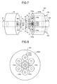
- FIG. 7 is a schematic view of an optical coupling structure according to an embodiment 4.
- An optical coupling structure 20A shown in FIG. 7 has the structure in which the ferrule 22b in the optical coupling structure 20 according to the embodiment 3 shown in FIG. 6 is replaced with a ferrule 22Ab.
- the multi-core optical fiber 21b and a plurality of the pumping-light-introducing optical fibers 27b are inserted through and fixed to the ferrule 22Ab so that respective facets of the multi-core optical fiber 21b and the pumping-light-introducing optical fibers 27b are positioned to be flush with a facet of the ferrule 22Ab.
- the optical filters 28 are disposed in the same number of the pumping-light-introducing optical fibers 27b.
- FIG. 8 is a drawing showing a facet of the ferrule 22Ab shown in FIG. 7 .
- the multi-core optical fiber 21b is disposed at the center of the ferrule 22Ab, and the six pumping-light-introducing optical fibers 27b are disposed to form a regular hexagon around outside the multi-core optical fiber 21b.
- the pumping-light-introducing optical fibers 27b disposed in the vertical direction of the drawing with respect to the multi-core optical fiber 21b are described.
- each of the optical filter 28s is configured and disposed to reflect the pumping light P1 outputted from the corresponding pumping-light-introducing core portion 27ba of the pumping-light-introducing optical fiber 27b and make the reflected pumping light P1 input, as the pumping light P2, to the inner cladding potion 21bb of the multi-core optical fiber 21b.
- the core portion 21ba can be pumped at a higher optical power.
- the optical filters 28 may not necessarily have to transmit light at wavelengths of those of the signal lights S1, S2, and S3 therethrough.
- FIG. 9 is a schematic view of an optical coupling structure according to an embodiment 5.
- An optical coupling structure 20B shown in FIG. 9 has a configuration in which the ferrule 22Ab is replaced with a ferrule 22Bb and the plurality of optical filters 28 is replaced with an optical filter 28B in one piece in the optical coupling structure 20A in the embodiment 4 shown in FIG. 7 .
- FIG. 10 is a drawing showing a facet of the ferrule 22Bb shown in FIG. 9 .
- the multi-core optical fiber 21b is disposed at the center of the ferrule 22Bb, and the six pumping-light-introducing optical fibers 27b are disposed to form a regular hexagon around outside the multi-core optical fiber 21b.
- the pumping-light-introducing optical fibers 27b disposed in the vertical direction of the drawing with respect to the multi-core optical fiber 21b are described.
- a facet 22Bba of the ferrule 22Bb is of a shape formed by cutting a tip portion from a cone at a surface perpendicular to the center axis of the cone. Since the pumping-light-introducing optical fibers 27b inserted through the ferrule 22Bb are shaped so that their facets are positioned to be flush with the facet 22Bba of the ferrule 22Bb, each facet of the pumping-light-introducing optical fiber 27b inclines outward with respect to the center (to a side of the multi-core optical fiber 21b). As a result of that, every pumping light P1 outputted from the pumping-light-introducing core portion 27ba of each of the pumping-light-introducing optical fiber 27b is outputted at an angle inclined inward with respect to the center.
- the optical filter 28B by disposing the optical filter 28B so that its main surface is perpendicular to the center axis of the multi-core optical fiber 21b (or the optical axis of the signal light S1), it is possible to reflect the pumping lights P1, outputted from all of the pumping-light-introducing core portions 27ba, collectively by the optical filter 28B in one piece and make the reflected pumping lights P1 input into the inner cladding potion 21bb of the multi-core optical fiber 21b as the pumping lights P2. By doing this, the number of the optical filters to be used can be reduced.
- FIG. 11 is a schematic view of an optical coupling structure according to an embodiment 4.
- An optical coupling structure 20C shown in FIG. 11 has the structure in which the lenses 3 and 4 in the optical coupling structure 20 according to the embodiment 3 shown in FIG. 6 are replaced with GRIN lenses 3A and 4A respectively.
- the optical coupling structure 20C using the GRIN lenses realizes optical coupling for optical amplification with a simple configuration.
- FIG. 12 is a schematic view of an optical fiber amplifier according to an embodiment 7 of the present invention.
- a cladding-pumping type optical fiber amplifier 100 includes optical isolators 101 and 102, wavelength division multiplexing (WDM) couplers 103 and 104, a pumping laser diode (LD) 105, an optical coupling structure 130, a multi-core erbium-doped optical fiber (EDF) 106, an optical coupling structure 140, WDM couplers 107 and 108, and optical isolators 109 and 110.
- WDM wavelength division multiplexing
- LD pumping laser diode
- EDF multi-core erbium-doped optical fiber
- the optical isolator 101 receives a signal light (for example, at a wavelength of 1520 nm to 1620 nm) outputted from a tunable laser source LS1 disposed outside the optical fiber amplifier 100, and outputs the received signal light to the WDM coupler 103.
- the WDM coupler 103 transmits therethrough and outputs the signal light to the optical coupling structure 130.
- the optical isolator 102 receives signal light outputted from a tunable laser source LS2 disposed outside the optical fiber amplifier 100, and outputs the received a signal light to the WDM coupler 104.
- the WDM coupler 104 transmits therethrough and outputs the signal light to the optical coupling structure 130.
- the multi-core EDF 106 is a double-cladding type multi-core optical fiber having a configuration similar to that of the multi-core optical fiber 21b shown in FIG. 6 and includes seven core portions, an inner cladding potion formed at an outer periphery of the core portion, and an outer cladding portion formed at an outer periphery of the inner cladding potion.
- One of the seven core portions is disposed in the vicinity of the center axis of the inner cladding potion, and the six core portions are disposed to form a regular hexagon around outside the one of the core portions.
- the mode field diameter of each of the core portion of the multi-core EDF 106 is approximately 7.3 ⁇ m at a wavelength of 1580 nm.
- a cutoff wavelength measured by using a 2-meter-length sample is 1050 nm as an average of the seven core portions.
- a separation distance between the core portions is 45 ⁇ m, and an outer diameter of the inner cladding potion is 180 ⁇ m.
- the core portion is doped with Er so that a loss coefficient at a wavelength of 1550 nm is 3.4 dB/m and a small-signal-gain coefficient is 4.3 dB/m.
- Cross-talk of light of each of the cores between cores of the multi-core EDF 106 is equal to or lower than - 40 dB at a wavelength of 1640 nm and a length of 16 m.
- the multi-core EDF 106 is 100 m in length, and its length is adjusted for making the signal light at a wavelength of 1570 nm to 1610 nm to be subjected to optical amplification preferably.
- the pumping LD 105 is, for example, a semiconductor LD, and outputs a multi-mode pumping light at a wavelength of 980 nm to the optical coupling structure 130.
- the optical coupling structure 130 is configured by optical fibers 131a and 131b which are single mode optical fibers connected to the WDM couplers 103 and 104 respectively, an optical fiber 131c which is a multi-mode optical fiber connected to the pumping LD 105, a multi-core EDF 131d which is one of end portions of the multi-core EDF 106, lenses 133a, 133b, and 133c as first lenses which are disposed to correspond to the optical fibers 131a, 131b, and 131c, and a lens 134 as a second lens which is disposed to correspond to the multi-core EDF 131d.
- the core portions of the optical fibers 131a, 131b, and 131c configure the plurality of first core portions.
- the optical coupling structure 140 is configured by optical fibers 141a and 141b which are single mode optical fibers connected to the WDM couplers 107 and 108 respectively, a multi-core EDF 141d which is the other one of the end portions of the multi-core EDF 106, a lens 144 as a first lens which is disposed to correspond to the multi-core EDF 141d, and lenses 143a and 143b as second lenses which is disposed to correspond to the optical fibers 141a and 141b.
- the core portions of the optical fibers 141a and 141b configure the plurality of second core portions.
- the lenses 134 and 144 are configured by, for example, a spherical lens, an aspherical lens, or a GRIN lens.
- the WDM coupler 107 transmits therethrough and outputs the signal lights amplified by the multi-core EDF 106 to the optical isolator 109 as explained hereinafter.
- the WDM coupler 108 transmits therethrough and outputs the signal lights amplified by the multi-core EDF 106 to the optical isolator 110.
- the optical isolators 109 and 110 are connected to an optical selective switch 200.
- the optical selective switch 200 is configured to be capable of selecting an arbitrary one of signal lights outputted from the optical isolators 109 and 110 and outputting the selected signal light to the optical spectrum analyzer OSA.
- the lens 133a collimates a signal light S31 from the tunable laser source LS1, which is outputted from the optical fiber 131a.
- the lens 133b collimates a signal light S32 from the tunable laser source LS2, which is outputted from the optical fiber 131b.
- the lens 133c collimates a pumping light P31 from the pumping LD 105, which is outputted from the optical fiber 131c.
- the lens 134 is configured to focus the collimated signal lights S31 and S32 to predetermined core portions of the multi-core EDF 131d collectively.
- the signal light S31 is focused to the center one of the seven core portions, and the signal light S32 is focused to one of the core portions disposed outside.
- the lens 134 makes the collimated pumping light P31 input into the inner cladding potion of the multi-core EDF 131d. By doing this, each core portion of the multi-core EDF 106 is pumped optically, and the signal lights S31 and S32 coupled to the predetermined ones of the core portions of the multi-core EDF 106 are subjected to optical amplification while propagating through the core portions.
- optical coupling is realized between the optical fibers 131a, 131b, and 131c and the multi-core EDF 131d by focusing the signal lights S31 and S32 outputted from each core portion of the optical fibers 131a, 131b, and 131c collectively to the corresponding core portion of the multi-core EDF 131d by the lens 134 in one piece. This can reduce the number of components constituting the optical coupling structure, and simplify the configuration.
- the lens 144 is configured to collectively collimate the signal lights S31 and S32 which are subjected to optical amplification by the multi-core EDF 106.
- the lens 143a focuses the collimated signal light S31 to the core portion of the optical fiber 141a.
- the lens 143b focuses the collimated signal light S32 to the core portion of the optical fiber 141b.
- optical coupling is realized between the optical fibers 141a and 141b and the multi-core EDF 141d by collimating the signal lights S31 and S32 outputted from the core portions of the multi-core EDF 141d collectively by the lens 144 in one piece.
- the number of components constituting the optical coupling structure can be reduced, and the configuration can be simplified.
- the lens 134 in some cases, there is a relationship of trade-off between efficiency in optically coupling the signal lights S31 and S32 to the core portion of the multi-core EDF 131d and efficiency in optically coupling the pumping light P31 to the inner cladding potion of the multi-core EDF 131d. That is, there is a case that, when the focusing position of the lens 134 is adjusted to enhance efficiency in optically coupling the signal lights S31 and S32 to the multi-core EDF 131d, efficiency in optically coupling the pumping light P31 to the inner cladding potion of the multi-core EDF 131d decreases.
- the focusing position of the lens 134 was adjusted so that, when signal light is at a wavelength of 1580 nm to 1610 nm, gain which is obtained by the multi-core EDF 106 is equal to or greater than 15 dB and cross-talk of light between cores of each of the cores of the multi-core EDF 106 is equal to or smaller than -30 dB.
- coupling losses of the pumping light P31 and the signal lights S31 and S32 were approximately 10 dB respectively.
- amplified spontaneous emission (ASE) spectrum was measured by the optical spectrum analyzer OSA. It should be noted that the power of a light outputted from the pumping LD 105 was set so that the pumping light of which optical power is 4.5 W is inputted into the inner cladding potion of the multi-core EDF 106. It is estimated that the pumping light of which optical power is 450 mW, which is 1/10 of 4.5 W is inputted into each core portion of the multi-core EDF 106.
- ASE spectrum was measured by using a single mode LD at a wavelength of 980 nm as a pumping light source and inputting the pumping light into a specific one of the core portions of the multi-core EDF 106 for pumping.
- the optical power of the pumping light inputted into the core portion in this situation was set at 450 mW.
- FIG. 13 is a drawing showing an ASE spectrum in the optical fiber amplifier 100.
- a legend "cladding pump” indicates a case that the pumping light is inputted into the inner cladding potion
- a legend "core pump” indicates a case that the pumping light is inputted into the specific one of the core portions.
- the core pump since the pumping light is inputted into the facet of the core portion, the core portion cannot be pumped sufficiently over the longitudinal direction of the multi-core EDF 106, and the power of ASE was low.
- the pumping light pumps each core portion gradually over the longitudinal direction of the multi-core EDF 106 while propagating in the inner cladding potion, the power of ASE was high.
- the signal light S31 at a wavelength of 1590 nm was inputted into the optical fiber amplifier 100 from the tunable laser source LS1, and the signal light S32 at a wavelength of 1591 nm was inputted into the optical fiber amplifier 100 from the tunable laser source LS2, and then optical gain characteristics were measured.
- Optical powers of the signal lights S31 and S32 were set so that optical powers inputted into the multi-core EDF 106 were - 15 dBm.
- the center one of the core portions into which the signal light S31 is inputted is described as "Core A" or "Inner Core”
- the outer core portions into which the signal light S32 is inputted is described as "Core B" or "Outer Core”.
- FIG. 14 is a drawing showing spectra of outputted signal lights when measuring optical gain characteristics.
- a solid line indicates an output spectrum in case that the signal light S31, outputted from the optical isolator 109 and selected with the optical selective switch 200 and then made output to the optical spectrum analyzer OSA, was measured.
- a solid line indicates an output spectrum in case that the signal light S32, outputted from the optical isolator 110 and selected with the optical selective switch 200 and then made output to the optical spectrum analyzer OSA, was measured.
- the vertical axis indicates relative power.
- each signal light although a signal light is outputted slightly from a core portion which is different from a core portion into which the signal light is inputted because of cross-talk of light, the cross-talk of light was equal to or lower than -30 dB (difference was equal to or greater than 30 dB).
- FIG. 15 is a drawing showing dependencies of gain, NF, and cross-talk (XT) on wavelength. It should be noted that gain and NF are gross values for the multi-core EDF 106, and cross-talk is a value for the optical fiber amplifier 100. As shown in FIG. 15 , in each core portion of "Inner Core” and "Outer Core", gain higher than 15 dB, NF lower than 5.5 dB, and cross-talk smaller than -30 dB were obtained for the signal light of which wavelength is 1580 nm to 1610 nm.
- FIG. 16 is a drawing showing a measurement system for bit error rate.
- a measurement system 1000 is configured by a signal light source 1001 capable of outputting a signal light of which wavelength is 1590 nm and to which a 10 Gbit/s non-return-to-zero (NRZ) signal of which pseudo-random binary sequence (PRBS) length is 2 31 -1 is superimposed, a 3-dB coupler 1002 dividing the signal light outputted from the signal light source 1001 into two, an optical fiber 1003 for generating two decorrelated signal lights from the two divided signal lights, an optical fiber 1004 as a delay line by 5 ns, the optical fiber amplifier 100 to be measured, the optical selective switch 200, a band-pass optical filter 1005 transmitting therethrough a signal light of which wavelength is 1590 nm, a variable optical attenuator 1006, an optical receiver 1007, and a bit error rate measurement instrument, not shown in the drawings, connected to the optical receiver 1007.
- NRZ non-return-to-zero
- the optical fiber amplifier 100 was operated under operation condition that the optical power of the signal light inputted into the multi-core EDF 106 was -15 dBm and the optical power of the amplified signal light outputted from the multi-core EDF 106 was +3 dBm.
- bit error rate was measured by inputting the signal light into "Core A” and "Core B" used when measuring the above-described gain characteristics.
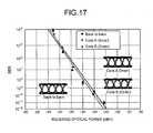
- FIG. 17 is a drawing showing bit error rate characteristics.
- the horizontal axis indicates received optical power in the optical receiver 1007.
- power penalty to "Back to back” when bit error rate (BER) is 10 -9 was smaller than 1 dB to a sufficient degree for either one of the "Core A” and “Core B".
- FIG. 17 shows eye patterns for "Back to back” and at times of optical amplification by "Core A”, and "Core B", deterioration of the eye patterns by optical amplification was not observed. Thereby, it was confirmed that the optical fiber amplifier 100 is capable of optical amplification without deteriorating the signal light.
- the optical fiber amplifier 100 is configured as forward pumping type, configuration of backward pumping type or bi-directional pumping type may be adopted.
- the number of signal lights to be inputted is two, it may be configured to input seven signal lights in accordance with the number of the core portions of the multi-core EDF 106.
- the number of pumping LDs to be used is not limited to one, and it may be configured to input pumping lights from a plurality of pumping LDs to the multi-core EDF 106.
- an optical fiber amplifier may be configured by using the optical coupling structures 20, 20A, or 20B shown in FIG. 6 , FIG. 7 or FIG. 9 , for example.
- the above-described embodiments do not limit the present invention.
- the present invention includes a configuration in which the above-described elements of the above-described embodiments are combined preferably.
- the present invention includes all of other embodiments, embodiment examples, and operational technologies etc. carried out based on the above-described embodiments by an ordinary skill person in the art.
- the optical coupling structure and the optical fiber amplifier according to the present invention are suitable for use in mainly optical communication.
Landscapes
- Physics & Mathematics (AREA)
- Electromagnetism (AREA)
- Optics & Photonics (AREA)
- Engineering & Computer Science (AREA)
- Plasma & Fusion (AREA)
- General Physics & Mathematics (AREA)
- Optical Couplings Of Light Guides (AREA)
- Lasers (AREA)
Abstract
Description
- The present invention relates to an optical coupling structure optically coupling a plurality of cores mutually and an optical fiber amplifier.
- In case of using a multi-core optical fiber in which a plurality of cores are disposed in a cladding, there is a case that an optical functional component such as an optical isolator or an optical filter etc. is inserted between two multi-core optical fibers. In addition, in case that a multi-core optical fiber has an optical amplification function, there is a case that an optical component inputting pumping light into the multi-core optical fiber is inserted between two multi-core optical fibers (for example, see
Patent Literature 1 or Non-Patent Literature 1). - Patent Literature 1: Japanese Laid-open Patent Publication No.
H10-125988 - Non-Patent Literature 1: P. M. Krummrich and Klaus Petermann, "Evaluation of Potential Optical Amplifier Concept for Coherent Mode Multiplexing", OFC2011, OMH5.
- Since the structure disclosed by Non-Patent
Literature 1 optically couples the plurality of cores mutually by using a lens array constituted by a plurality of lenses disposed to correspond to each core, there is a problem that the number of components constituting the structure for optical coupling increases and the structure becomes complex. - The present invention was conceived in consideration of the above-described circumstances, and it is an object to provide an optical coupling structure capable of optically coupling a plurality of cores mutually with a simple structure, and an optical fiber amplifier using this.
- In order to solve the above-described problem and achieve the object, an optical coupling structure according to the present invention is an optical coupling structure optically coupling a plurality of core portions and a plurality of core portions, the optical coupling structure including: a plurality of first core portions outputting a plurality of lights; a first lens focusing or collimating the plurality of lights outputted from the plurality of first core portions; a second lens focusing the plurality of lights focused or collimated by the first lens; a plurality of second core portions, the plurality of lights focused by the second lens being inputted into the second core portions respectively; and an optical functional component disposed between the first lens and the second lens, the plurality of lights being inputted into the optical functional component. At least one of the first lens and the second lens is configured by a lens or a lens group focusing or collimating the plurality of lights collectively.
- In addition, in the optical coupling structure according to the present invention, the first lens and the second lens are configured so that an inverted image is formed between the first core portions and the second core portions.
- In addition, in the optical coupling structure according to the present invention, an inverted image and an erect image are formed between the first core portions and the second core portions.
- In addition, in the optical coupling structure according to the present invention, at least one of the plurality of the first core portions and the plurality of the second core portions configures a multi-core optical fiber.
- In addition, in the optical coupling structure according to the present invention, one of the plurality of the first core portions and the plurality of the second core portions is doped with a rare earth element and configures a multi-core optical fiber, and the multi-core optical fiber comprises an inner cladding potion formed at outer peripheries of the plurality of core portions doped with the rare earth element and an outer cladding portion formed at an outer periphery of the inner cladding potion.
- In addition, in the optical coupling structure according to the present invention further includes at least a pumping-light-introducing core portion outputting a pumping light for optically pumping the rare earth element. The optical functional component is an optical filter inputting the pumping light outputted from the pumping-light-introducing core portion into the inner cladding potion.
- In addition, in the optical coupling structure according to the present invention, the optical filter inputs the pumping light into the inner cladding potion so that an optical axis of the pumping light coincides with a center axis of the inner cladding potion of the multi-core optical fiber.
- In addition, an optical fiber amplifier according to the present invention includes the optical coupling structure according to the present invention.
- The present invention obtains an effect capable of realizing an optical coupling structure with a simple structure.
-
-
FIG. 1 is a schematic view of an optical coupling structure according to anembodiment 1. -
FIG. 2 is a drawing showing optical paths of signal lights inFIG. 1 . -
FIG. 3 is a schematic view of an optical coupling structure according to anembodiment 2. -
FIG. 4 is a drawing showing an example of optical paths of signal lights inFIG. 3 . -
FIG. 5 is a drawing showing optical paths in an optical coupling structure according to a modification example of theembodiment 2. -
FIG. 6 is a schematic view of an optical coupling structure according to anembodiment 3. -
FIG. 7 is a schematic view of an optical coupling structure according to anembodiment 4. -
FIG. 8 is a drawing showing a facet of a ferrule shown inFIG. 7 . -
FIG. 9 is a schematic view of an optical coupling structure according to anembodiment 5. -
FIG. 10 is a drawing showing a facet of a ferrule shown inFIG. 9 . -
FIG. 11 is a schematic view of an optical coupling structure according to an embodiment 6. -
FIG. 12 is a schematic view of an optical fiber amplifier according to an embodiment 7. -
FIG. 13 is a drawing showing ASE spectra. -
FIG. 14 is a drawing showing spectra of outputted signal lights. -
FIG. 15 is a drawing showing dependencies of gain, NF, and cross-talk on wavelength. -
FIG. 16 is a drawing showing a measurement system for bit error rate. -
FIG. 17 is a drawing showing bit error rate characteristics. - Hereinafter, embodiments of an optical coupling structure and an optical fiber amplifier according to the present invention will be explained in detail with reference to the drawings. It should be noted that the invention is not limited by these embodiments. In addition, in each drawing, identical or equivalent elements are given same reference numerals. Furthermore, it must be noted that the drawings are schematic depictions, and may not represent the actual relation of dimension of each element. In some cases, different drawings may include portions using different scales and dimensional relations.
-
FIG. 1 is a schematic view of an optical coupling structure according to anembodiment 1 of the present invention. Anoptical coupling structure 10 is constituted by multi-coreoptical fibers ferrules optical fibers lens 3 as a first lens, alens 4 as a second lens, and an opticalfunctional component 5. - The multi-core
optical fiber 1a is made from silica-based glass and includes seven core portions 1aa as a plurality of first core portions and a cladding portion 1ab formed at outer peripheries of the core portions 1aa. The seven core portions 1aa constitute the multi-coreoptical fiber 1a so that six core portions are disposed to form a regular hexagon around outside the center one of the core portions disposed in the vicinity of a center axis of the cladding portion 1ab. Similarly, the multi-coreoptical fiber 1b is made from silica-based glass and includes seven core portions 1ba as a plurality of second core portions and a cladding portion 1bb formed at outer peripheries of the core portions 1ba. The seven core portions 1ba constitute the multi-coreoptical fiber 1b so that six core portions are disposed to form a regular hexagon around outside the center one of the core portions disposed in the vicinity of a center axis of the cladding portion 1bb. - The
ferrules optical fibers ferrules optical fibers ferrules - Each core portion 1aa outputs a signal light having been propagated through each core portion 1aa. The wavelength of the signal light is, for example, a wavelength in 1.55 µm wavelength band which is frequently used in optical communication. It should be noted that, although signal lights are outputted from all of the seven core portions 1aa, for the purpose of simplifying the description, as signal light herein, a signal light S1 outputted from the center one of the core portions 1aa and signal lights S2 and S3 outputted from the core portions disposed in a vertical direction of the drawing with respect to the center one of the core portions are typified and described.
- The
lens 3 is configured so that the signal lights S1, S2, and S3 outputted from the core portions 1aa are collimated collectively. Thelens 3 is configured as, for example, a spherical lens or an aspherical lens. - The collimated signal lights S1, S2, and S3 are inputted into the optical
functional component 5. The opticalfunctional component 5 is a component such as, for example, an optical isolator or an optical filter etc., exerting a predetermined function to inputted lights. It is preferable that the signal lights S1, S2, and S3 are inputted as collimated parallel lights because thereby the opticalfunctional component 5 can exert its function the most effectively to the signal lights S1, S2, and S3. - The
lens 4 is configured so that each of the signal lights S1, S2, and S3 outputted from the opticalfunctional component 5 is focused to corresponding one of the seven core portions 1ba of the multi-coreoptical fiber 1b. Thelens 4 is configured as, for example, a spherical lens or an aspherical lens. -
FIG. 2 is a drawing showing optical paths of the signal lights S1, S2, and S3 inFIG. 1 . Theoptical coupling structure 10 realizes optical coupling between the core portions 1aa and the core portions 1ba by collimating the signal lights S1, S2, and S3 outputted from the core portions 1aa collectively by thelens 3 in one piece and focusing the collimated signal lights collectively to the corresponding one of the core portions 1ba by thelens 4 in one piece. It should be noted that the signal lights S2 and S3 outputted from the upper or the lower one of the core portions 1aa with respect to the center are inverted vertically and focused to each core portion 1ba. This reduces the more number of components constituting an optical coupling structure, simplifies the structure to a greater extent compared to a conventional case where optical coupling is conducted among a plurality of core portions by using a lens array constituted by a plurality of lenses corresponding to the number of the core portion. In addition, since this reduces greater number of lenses to be used, positions between lenses can be adjusted easily. - In addition, since orientation of the multi-core optical fiber in the rotational direction can be distinguished easily by, for example, disposing a marker at the
ferrule optical coupling structure 10 by configuring theoptical coupling structure 10 so that the marker is inverted vertically. It is further preferable to dispose a marker to a multi-core optical fiber similarly to correspond to the marker disposed to the ferrule. - It should be noted that optical coupling loss between the core portions 1aa and the core portions 1ba can be low as, for example, approximately equal to or lower than 0.3 dB if interval between the core portions 1aa and interval between the core portions 1ba are approximately equal to or lower than 62.5 µm respectively.
-
FIG. 3 is a schematic view of an optical coupling structure according to anembodiment 2 of the present invention. Anoptical coupling structure 10A has the structure in which thelenses optical coupling structure 10 according to theembodiment 1 shown inFIG. 1 are replaced with gradient-index (GRIN)-type lenses - The
optical coupling structure 10A realizes optical coupling between the core portions 1aa and the core portions 1ba by collimating the signal lights S1, S2, and S3 outputted from the core portions 1aa collectively by theGRIN lens 3A in one piece and focusing the collimated signal lights collectively to the corresponding core portions 1ba by theGRIN lens 4A in one piece. Similarly to theembodiment 1, this can reduce the number of components constituting the optical coupling structure, and simplify the configuration. -
FIG. 4 is a drawing showing an example of optical paths of signal lights S1, S2, and S3 inFIG. 3 . The lengths or the refractive index distributions of theGRIN lenses FIG. 4 are designed so that the signal lights S1, S2, and S3 are focused on the core portions 1ba as images inverted vertically relative to a state of being outputted from the core portions 1aa. - It should be noted that, although the
GRIN lenses functional component 5, and the multi-coreoptical fibers FIG. 3 , these components may contact directly with one another and fixed by adhesive etc. By doing this, the configuration and production can be facilitated furthermore. -
FIG. 5 is a drawing showing optical paths in an optical coupling structure according to a modification example of theembodiment 2. This optical coupling structure has the structure in which theGRIN lens 4A in theoptical coupling structure 10A is replaced with aGRIN lens 4B. TheGRIN lens 4B is configured to be longer than theGRIN lens 4A. By doing this, theGRIN lens 4B focuses an inverted image inside the GRIN lens, and after that, focuses an image so that positional relationship of the signal lights S1, S2, and S3 becomes positional relationship for an erect image. In this manner, theGRIN lens 4B may be used in place of theGRIN lens 4A. It should be noted that, in place of theGRIN lens 4A, theGRIN lens 3A may be elongated like theGRIN lens 4B. - As described above, the optical coupling structure using the GRIN lens forms an inverted image at least once between a core portion outputting light and a core portion into which light is inputted. In addition, as for GRIN lenses, an optical functional component is disposed between two GRIN lenses in a state in which the GRIN lenses are disposed so that light outputted from each core portion of the multi-core optical fiber become substantial collimated light between the GRIN lenses as shown in
FIG. 4 orFIG. 5 . By doing this, parallel light is inputted into the optical functional component. It should be noted that, in case of an erect image being formed as shown inFIG. 5 , there are a plurality of points where the light outputted from each core portion becomes a collimated light. That is, for example, inFIG. 5 , a point exists in theGRIN lens 4B where the signal lights S1, S2, and S3 become collimated lights. In this case, theGRIN lens 4B may be divided into two portions at a point where the signal lights S1, S2, and S3 become collimated light and an optical functional component may be interposed between the divided portions of the GRIN lens. In addition, since an inverted image and an erect image are formed alternately, the length and the refractive index distribution of the GRIN lens may be set so that either of the inverted image and the erect image is formed multiple times. The GRIN lens in this state may be divided at each of multiple points where a light outputted from the core portion becomes collimated light, and optical functional components may be interposed between each of the divided GRIN lens similarly to the above description. -
FIG. 6 is a schematic view of an optical coupling structure according to anembodiment 3 of the present invention. Anoptical coupling structure 20 is constituted by multi-coreoptical fibers ferrules optical fibers lens 3 as the first lens, thelens 4 as the second lens, the opticalfunctional component 5, anoptical filter 28 as an optical functional component, and a pumping-light-introducingoptical fiber 27b inserted through theferrule 22b. - Since the configurations for the multi-core
optical fiber 1a, theferrule 2a, thelens 3, thelens 4, and the opticalfunctional component 5 are the same as those corresponding to the components of theembodiment 1 shown inFIG. 1 , description for them is omitted. - The multi-core
optical fiber 21b includes seven core portions 21ba as a plurality of second core portions, an inner cladding potion 21bb formed at outer peripheries of the core portions 21ba, and an outer cladding portion 21bc formed at an outer periphery of the inner cladding potion 21bb. - The core portion 21ba is made from silica-based glass which is doped with a rare earth element such as erbium (Er), ytterbium (Yb), neodymium (Nd), or thulium (Tm), etc. The inner cladding potion 21bb is made from silica-based glass of which refractive index is lower than that of the core portion 21ba. The outer cladding portion 21bc is made from, for example, optical resin of which refractive index is lower than that of the inner cladding potion 21bb.
- That is, the multi-core
optical fiber 21b is configured as a double-cladding type optical gain fiber. - The pumping-light-introducing
optical fiber 27b is made from silica-based glass and includes a pumping-light-introducing core portion 27ba and a cladding portion 27bb formed at an outer periphery of the pumping-light-introducing core portion 27ba. The pumping-light-introducingoptical fiber 27b outputs a pumping light P1, outputted from a pumpinglight source 30 such as semiconductor laser etc. and having propagated through the pumping-light-introducing core portion 27ba, from the pumping-light-introducing core portion 27ba. The wavelength of the pumping light P1 is wavelength capable of optically pumping the rare earth element doped to the core portion 21ba of the multi-coreoptical fiber 21b, and is 0.98 µm wavelength band etc., for example, in case of Er. In addition, various kinds of optical fiber, such as a single mode optical fiber, a multi-mode optical fiber, or a multi-core optical fiber of single mode or multi-mode can be used for the pumping-light-introducingoptical fiber 27b. For the pumpinglight source 30, a single mode pumping light source or a multi-mode-pumping light source can be used in accordance with the kind of the pumping-light-introducingoptical fiber 27b. - The
ferrule 22b is a kind of ferrule called as a duplex ferrule. The multi-coreoptical fiber 21b and the pumping-light-introducingoptical fiber 27b are inserted through and fixed to theferrule 22b. Respective facets of the multi-coreoptical fiber 21b and the pumping-light-introducingoptical fiber 27b are positioned to be flush with a facet of theferrule 22b. In thepresent embodiment 3, although the multi-coreoptical fiber 21b and the pumping-light-introducingoptical fiber 27b in a state of being parallel with each other are inserted through theferrule 22b, they may be inserted in a state of being oblique to each other. - The
optical filter 28 made of, for example, a dielectric multilayered filter is configured and disposed to reflect the pumping light P1 introduced by thelens 4 and make the reflected pumping light P1 inputted into the inner cladding potion 21bb of the multi-coreoptical fiber 21b as the pumping light P2. In addition, theoptical filter 28 has wavelength characteristics of reflecting light at the wavelength of the pumping light P1 but transmits therethrough light at the wavelengths of the signal lights S1, S2, and S3 as described hereinafter. The pumping light P2 reflected by theoptical filter 28 is coupled with each core portion 21ba gradually while being propagated in the inner cladding potion 21bb of the multi-coreoptical fiber 21b and pumps the rare earth element doped to each of the core portions 21ba. By doing this, the pumping light P2 can pump the seven core portions 21ba collectively. - Herein when the signal lights S1, S2 and S3 (1.55 µm wavelength band or 1.58 µm wavelength band etc., in case of, for example, Er) to be amplified optically have been propagated through and outputted from the multi-core
optical fiber 1a, theoptical coupling structure 20 realizes optical coupling between the core portions 1aa and the core portions 21ba by collimating the signal lights S1, S2, and S3 collectively by thelens 3 in one piece and focusing the collimated signal lights collectively to the corresponding core portions 21ba by thelens 4 in one piece. Each of the signal lights S1, S2, and S3 subjected to optical coupling to the core portions 21ba is, while being propagated in each of the core portions 21ba, subjected to optical amplification by an act of stimulated emission of the rare earth element. - As described above, the
optical coupling structure 20 realizes optical coupling with a simple configuration for optical amplification. - It should be noted that, although the distance between center axes of the multi-core
optical fiber 21b and the pumping-light-introducingoptical fiber 27b is, for example, equal to or longer than 125 µm, since this is not large to a significant degree, a reflection angle at which the pumping light P1 is reflected by theoptical filter 28 to become the pumping light P2 is extremely small. Therefore, it is possible to reduce optical coupling loss of the pumping light between the pumping-light-introducingoptical fiber 27b and the multi-coreoptical fiber 21b by adjusting the angle at which theoptical filter 28 is tilted. - In addition, for the purpose of enhancing coupling efficiency for the pumping light P2, it is preferable that the
optical filter 28 makes the pumping light P2 input into the inner cladding potion 21bb so that the optical axis of the pumping light P2 coincides with the center axis of the inner cladding potion 21bb of the multi-coreoptical fiber 21b. Therefore, for realizing this, it is preferable that the position or the angle etc. of theoptical filter 28 is adjusted. However, the position at which theoptical filter 28 makes the pumping light P2 input onto the inner cladding potion 21bb is not limited specifically, the position at which the pumping light P2 is inputted can be set arbitrarily by adjusting the position or the angle etc. of theoptical filter 28. The pumping state and the gain of each core portion 21ba can be varied by adjusting the position at which the pumping light P2 is made input. Therefore, for example, the position at which the pumping light P2 is made input may be adjusted so that the gains at the respective core portions 21ba become more uniform. - In addition, the
optical coupling structure 20 has a configuration which can be adapted to so-called forward pumping type of pumping method, in which the propagation directions of the signal lights S1, S2, and S3 are identical with the propagation direction of the pumping light P2. However, if propagation directions of the signal lights S1, S2, and S3 are changed so that the core portions 21ba are the first core portions outputting signal lights and the core portions 1aa are the second core portions into which the signal lights are inputted, the propagation directions of the signal lights S1, S2, and S3 are opposite to the propagation direction of the pumping light P2. By doing this way, it is possible to configure an optical coupling structure which can be adapted to backward pumping type of pumping method. -
FIG. 7 is a schematic view of an optical coupling structure according to anembodiment 4. Anoptical coupling structure 20A shown inFIG. 7 has the structure in which theferrule 22b in theoptical coupling structure 20 according to theembodiment 3 shown inFIG. 6 is replaced with a ferrule 22Ab. The multi-coreoptical fiber 21b and a plurality of the pumping-light-introducingoptical fibers 27b are inserted through and fixed to the ferrule 22Ab so that respective facets of the multi-coreoptical fiber 21b and the pumping-light-introducingoptical fibers 27b are positioned to be flush with a facet of the ferrule 22Ab. Furthermore, theoptical filters 28 are disposed in the same number of the pumping-light-introducingoptical fibers 27b. -
FIG. 8 is a drawing showing a facet of the ferrule 22Ab shown inFIG. 7 .
As shown inFIG. 8 , the multi-coreoptical fiber 21b is disposed at the center of the ferrule 22Ab, and the six pumping-light-introducingoptical fibers 27b are disposed to form a regular hexagon around outside the multi-coreoptical fiber 21b. It should be noted that, for the purpose of simplifyingFIG. 7 , only the pumping-light-introducingoptical fibers 27b disposed in the vertical direction of the drawing with respect to the multi-coreoptical fiber 21b are described. - In addition, each of the optical filter 28s is configured and disposed to reflect the pumping light P1 outputted from the corresponding pumping-light-introducing core portion 27ba of the pumping-light-introducing
optical fiber 27b and make the reflected pumping light P1 input, as the pumping light P2, to the inner cladding potion 21bb of the multi-coreoptical fiber 21b. - Since in the
optical coupling structure 20A, the plurality of pumping lights P1, outputted from the pumping-light-introducing core portions 27ba of the six pumping-light-introducingoptical fibers 27b are reflected by the plurality ofoptical filters 28 and the reflected pumping lights P1 are made input into the inner cladding potions 21bb of the multi-coreoptical fiber 21b, the core portion 21ba can be pumped at a higher optical power. - It should be noted that, as shown in
FIG. 7 in case of disposing theoptical filters 28 so as not to interfere with the signal lights S1, S2, and S3, theoptical filters 28 may not necessarily have to transmit light at wavelengths of those of the signal lights S1, S2, and S3 therethrough. -
FIG. 9 is a schematic view of an optical coupling structure according to anembodiment 5. Anoptical coupling structure 20B shown inFIG. 9 has a configuration in which the ferrule 22Ab is replaced with a ferrule 22Bb and the plurality ofoptical filters 28 is replaced with anoptical filter 28B in one piece in theoptical coupling structure 20A in theembodiment 4 shown inFIG. 7 . -
FIG. 10 is a drawing showing a facet of the ferrule 22Bb shown inFIG. 9 .
As shown inFIG. 10 , the multi-coreoptical fiber 21b is disposed at the center of the ferrule 22Bb, and the six pumping-light-introducingoptical fibers 27b are disposed to form a regular hexagon around outside the multi-coreoptical fiber 21b. It should be noted that, for the purpose of simplifyingFIG. 9 , only the pumping-light-introducingoptical fibers 27b disposed in the vertical direction of the drawing with respect to the multi-coreoptical fiber 21b are described. - A facet 22Bba of the ferrule 22Bb is of a shape formed by cutting a tip portion from a cone at a surface perpendicular to the center axis of the cone. Since the pumping-light-introducing
optical fibers 27b inserted through the ferrule 22Bb are shaped so that their facets are positioned to be flush with the facet 22Bba of the ferrule 22Bb, each facet of the pumping-light-introducingoptical fiber 27b inclines outward with respect to the center (to a side of the multi-coreoptical fiber 21b). As a result of that, every pumping light P1 outputted from the pumping-light-introducing core portion 27ba of each of the pumping-light-introducingoptical fiber 27b is outputted at an angle inclined inward with respect to the center. - As a result of that, by disposing the
optical filter 28B so that its main surface is perpendicular to the center axis of the multi-coreoptical fiber 21b (or the optical axis of the signal light S1), it is possible to reflect the pumping lights P1, outputted from all of the pumping-light-introducing core portions 27ba, collectively by theoptical filter 28B in one piece and make the reflected pumping lights P1 input into the inner cladding potion 21bb of the multi-coreoptical fiber 21b as the pumping lights P2. By doing this, the number of the optical filters to be used can be reduced. -
FIG. 11 is a schematic view of an optical coupling structure according to anembodiment 4. Anoptical coupling structure 20C shown inFIG. 11 has the structure in which thelenses optical coupling structure 20 according to theembodiment 3 shown inFIG. 6 are replaced withGRIN lenses - As described above, also the
optical coupling structure 20C using the GRIN lenses realizes optical coupling for optical amplification with a simple configuration. -
FIG. 12 is a schematic view of an optical fiber amplifier according to an embodiment 7 of the present invention. As shown inFIG. 12 , a cladding-pumping typeoptical fiber amplifier 100 includesoptical isolators couplers optical coupling structure 130, a multi-core erbium-doped optical fiber (EDF) 106, anoptical coupling structure 140,WDM couplers optical isolators - The
optical isolator 101 receives a signal light (for example, at a wavelength of 1520 nm to 1620 nm) outputted from a tunable laser source LS1 disposed outside theoptical fiber amplifier 100, and outputs the received signal light to theWDM coupler 103. TheWDM coupler 103 transmits therethrough and outputs the signal light to theoptical coupling structure 130. Similarly, theoptical isolator 102 receives signal light outputted from a tunable laser source LS2 disposed outside theoptical fiber amplifier 100, and outputs the received a signal light to theWDM coupler 104. TheWDM coupler 104 transmits therethrough and outputs the signal light to theoptical coupling structure 130. - The
multi-core EDF 106 is a double-cladding type multi-core optical fiber having a configuration similar to that of the multi-coreoptical fiber 21b shown inFIG. 6 and includes seven core portions, an inner cladding potion formed at an outer periphery of the core portion, and an outer cladding portion formed at an outer periphery of the inner cladding potion. One of the seven core portions is disposed in the vicinity of the center axis of the inner cladding potion, and the six core portions are disposed to form a regular hexagon around outside the one of the core portions. - The mode field diameter of each of the core portion of the
multi-core EDF 106 is approximately 7.3 µm at a wavelength of 1580 nm. A cutoff wavelength measured by using a 2-meter-length sample is 1050 nm as an average of the seven core portions. A separation distance between the core portions is 45 µm, and an outer diameter of the inner cladding potion is 180 µm. The core portion is doped with Er so that a loss coefficient at a wavelength of 1550 nm is 3.4 dB/m and a small-signal-gain coefficient is 4.3 dB/m. Cross-talk of light of each of the cores between cores of themulti-core EDF 106 is equal to or lower than - 40 dB at a wavelength of 1640 nm and a length of 16 m. Themulti-core EDF 106 is 100 m in length, and its length is adjusted for making the signal light at a wavelength of 1570 nm to 1610 nm to be subjected to optical amplification preferably. - The pumping
LD 105 is, for example, a semiconductor LD, and outputs a multi-mode pumping light at a wavelength of 980 nm to theoptical coupling structure 130. - The
optical coupling structure 130 is configured byoptical fibers WDM couplers pumping LD 105, amulti-core EDF 131d which is one of end portions of themulti-core EDF 106,lenses optical fibers lens 134 as a second lens which is disposed to correspond to themulti-core EDF 131d. The core portions of theoptical fibers - The
optical coupling structure 140 is configured byoptical fibers WDM couplers multi-core EDF 141d which is the other one of the end portions of themulti-core EDF 106, alens 144 as a first lens which is disposed to correspond to themulti-core EDF 141d, andlenses optical fibers optical fibers lenses - The
WDM coupler 107 transmits therethrough and outputs the signal lights amplified by themulti-core EDF 106 to theoptical isolator 109 as explained hereinafter. Similarly, theWDM coupler 108 transmits therethrough and outputs the signal lights amplified by themulti-core EDF 106 to theoptical isolator 110. Theoptical isolators selective switch 200. The opticalselective switch 200 is configured to be capable of selecting an arbitrary one of signal lights outputted from theoptical isolators - In the
optical coupling structure 130, thelens 133a collimates a signal light S31 from the tunable laser source LS1, which is outputted from theoptical fiber 131a. Thelens 133b collimates a signal light S32 from the tunable laser source LS2, which is outputted from theoptical fiber 131b. Thelens 133c collimates a pumping light P31 from the pumpingLD 105, which is outputted from the optical fiber 131c. - The
lens 134 is configured to focus the collimated signal lights S31 and S32 to predetermined core portions of themulti-core EDF 131d collectively.
The signal light S31 is focused to the center one of the seven core portions, and the signal light S32 is focused to one of the core portions disposed outside. In addition, thelens 134 makes the collimated pumping light P31 input into the inner cladding potion of themulti-core EDF 131d. By doing this, each core portion of themulti-core EDF 106 is pumped optically, and the signal lights S31 and S32 coupled to the predetermined ones of the core portions of themulti-core EDF 106 are subjected to optical amplification while propagating through the core portions. - In the
optical coupling structure 130, optical coupling is realized between theoptical fibers multi-core EDF 131d by focusing the signal lights S31 and S32 outputted from each core portion of theoptical fibers multi-core EDF 131d by thelens 134 in one piece. This can reduce the number of components constituting the optical coupling structure, and simplify the configuration. - On the other hand, in the
optical coupling structure 140, thelens 144 is configured to collectively collimate the signal lights S31 and S32 which are subjected to optical amplification by themulti-core EDF 106. Thelens 143a focuses the collimated signal light S31 to the core portion of theoptical fiber 141a. Similarly, thelens 143b focuses the collimated signal light S32 to the core portion of theoptical fiber 141b. - In the
optical coupling structure 140, optical coupling is realized between theoptical fibers multi-core EDF 141d by collimating the signal lights S31 and S32 outputted from the core portions of themulti-core EDF 141d collectively by thelens 144 in one piece. By doing this, the number of components constituting the optical coupling structure can be reduced, and the configuration can be simplified. - Herein, regarding the
lens 134, in some cases, there is a relationship of trade-off between efficiency in optically coupling the signal lights S31 and S32 to the core portion of themulti-core EDF 131d and efficiency in optically coupling the pumping light P31 to the inner cladding potion of themulti-core EDF 131d. That is, there is a case that, when the focusing position of thelens 134 is adjusted to enhance efficiency in optically coupling the signal lights S31 and S32 to themulti-core EDF 131d, efficiency in optically coupling the pumping light P31 to the inner cladding potion of themulti-core EDF 131d decreases. On the other hand, there is a case that, when the focusing position of thelens 134 is adjusted to enhance efficiency in optically coupling the pumping light P31 to the inner cladding potion of themulti-core EDF 131d, efficiency in optically coupling the signal lights S31 and S32 to the core portion of themulti-core EDF 131d decreases, and cross-talk between cores of each of the cores deteriorates. - In the following measurement, the focusing position of the
lens 134 was adjusted so that, when signal light is at a wavelength of 1580 nm to 1610 nm, gain which is obtained by themulti-core EDF 106 is equal to or greater than 15 dB and cross-talk of light between cores of each of the cores of themulti-core EDF 106 is equal to or smaller than -30 dB. In this state of theoptical coupling structure 130, coupling losses of the pumping light P31 and the signal lights S31 and S32 were approximately 10 dB respectively. - Herein in a state that a signal light is not inputted into the
optical fiber amplifier 100 and the pumping light is outputted from the pumpingLD 105, amplified spontaneous emission (ASE) spectrum was measured by the optical spectrum analyzer OSA. It should be noted that the power of a light outputted from the pumpingLD 105 was set so that the pumping light of which optical power is 4.5 W is inputted into the inner cladding potion of themulti-core EDF 106. It is estimated that the pumping light of which optical power is 450 mW, which is 1/10 of 4.5 W is inputted into each core portion of themulti-core EDF 106. - In addition, for comparison, ASE spectrum was measured by using a single mode LD at a wavelength of 980 nm as a pumping light source and inputting the pumping light into a specific one of the core portions of the
multi-core EDF 106 for pumping. The optical power of the pumping light inputted into the core portion in this situation was set at 450 mW. -
FIG. 13 is a drawing showing an ASE spectrum in theoptical fiber amplifier 100. A legend "cladding pump" indicates a case that the pumping light is inputted into the inner cladding potion, and a legend "core pump" indicates a case that the pumping light is inputted into the specific one of the core portions. As shown inFIG. 13 , in case of the "core pump", since the pumping light is inputted into the facet of the core portion, the core portion cannot be pumped sufficiently over the longitudinal direction of themulti-core EDF 106, and the power of ASE was low.
On the other hand, in case of the "cladding pump", since the pumping light pumps each core portion gradually over the longitudinal direction of themulti-core EDF 106 while propagating in the inner cladding potion, the power of ASE was high. - Next, the signal light S31 at a wavelength of 1590 nm was inputted into the
optical fiber amplifier 100 from the tunable laser source LS1, and the signal light S32 at a wavelength of 1591 nm was inputted into theoptical fiber amplifier 100 from the tunable laser source LS2, and then optical gain characteristics were measured. Optical powers of the signal lights S31 and S32 were set so that optical powers inputted into themulti-core EDF 106 were - 15 dBm. In the following, the center one of the core portions into which the signal light S31 is inputted is described as "Core A" or "Inner Core", and the outer core portions into which the signal light S32 is inputted is described as "Core B" or "Outer Core". -
FIG. 14 is a drawing showing spectra of outputted signal lights when measuring optical gain characteristics. InFIG. 14 , a solid line indicates an output spectrum in case that the signal light S31, outputted from theoptical isolator 109 and selected with the opticalselective switch 200 and then made output to the optical spectrum analyzer OSA, was measured. A solid line indicates an output spectrum in case that the signal light S32, outputted from theoptical isolator 110 and selected with the opticalselective switch 200 and then made output to the optical spectrum analyzer OSA, was measured. In addition, the vertical axis indicates relative power. - As shown in
FIG. 14 , regarding each signal light, although a signal light is outputted slightly from a core portion which is different from a core portion into which the signal light is inputted because of cross-talk of light, the cross-talk of light was equal to or lower than -30 dB (difference was equal to or greater than 30 dB). - Next, gain, noise figure (NF), and cross-talk were measured while varying the wavelengths of the signal lights S31 and S32.
FIG. 15 is a drawing showing dependencies of gain, NF, and cross-talk (XT) on wavelength. It should be noted that gain and NF are gross values for themulti-core EDF 106, and cross-talk is a value for theoptical fiber amplifier 100. As shown inFIG. 15 , in each core portion of "Inner Core" and "Outer Core", gain higher than 15 dB, NF lower than 5.5 dB, and cross-talk smaller than -30 dB were obtained for the signal light of which wavelength is 1580 nm to 1610 nm. - Next, bit error rate was measured for the
optical fiber amplifier 100.FIG. 16 is a drawing showing a measurement system for bit error rate. Ameasurement system 1000 is configured by asignal light source 1001 capable of outputting a signal light of which wavelength is 1590 nm and to which a 10 Gbit/s non-return-to-zero (NRZ) signal of which pseudo-random binary sequence (PRBS) length is 231-1 is superimposed, a 3-dB coupler 1002 dividing the signal light outputted from thesignal light source 1001 into two, anoptical fiber 1003 for generating two decorrelated signal lights from the two divided signal lights, anoptical fiber 1004 as a delay line by 5 ns, theoptical fiber amplifier 100 to be measured, the opticalselective switch 200, a band-passoptical filter 1005 transmitting therethrough a signal light of which wavelength is 1590 nm, a variableoptical attenuator 1006, anoptical receiver 1007, and a bit error rate measurement instrument, not shown in the drawings, connected to theoptical receiver 1007. - The
optical fiber amplifier 100 was operated under operation condition that the optical power of the signal light inputted into themulti-core EDF 106 was -15 dBm and the optical power of the amplified signal light outputted from themulti-core EDF 106 was +3 dBm. In addition, bit error rate was measured by inputting the signal light into "Core A" and "Core B" used when measuring the above-described gain characteristics. -
FIG. 17 is a drawing showing bit error rate characteristics. The horizontal axis indicates received optical power in theoptical receiver 1007. As shown inFIG. 17 , power penalty to "Back to back" when bit error rate (BER) is 10-9 was smaller than 1 dB to a sufficient degree for either one of the "Core A" and "Core B". In addition, althoughFIG. 17 shows eye patterns for "Back to back" and at times of optical amplification by "Core A", and "Core B", deterioration of the eye patterns by optical amplification was not observed. Thereby, it was confirmed that theoptical fiber amplifier 100 is capable of optical amplification without deteriorating the signal light. - It should be noted that, although the
optical fiber amplifier 100 according to the above-described embodiments is configured as forward pumping type, configuration of backward pumping type or bi-directional pumping type may be adopted. In addition, in theoptical fiber amplifier 100 according to the above-described embodiments, the number of signal lights to be inputted is two, it may be configured to input seven signal lights in accordance with the number of the core portions of themulti-core EDF 106. In addition, the number of pumping LDs to be used is not limited to one, and it may be configured to input pumping lights from a plurality of pumping LDs to themulti-core EDF 106. In addition, an optical fiber amplifier may be configured by using theoptical coupling structures FIG. 6 ,FIG. 7 orFIG. 9 , for example. - Also, it should be noted that the above-described embodiments do not limit the present invention. The present invention includes a configuration in which the above-described elements of the above-described embodiments are combined preferably. Furthermore, the present invention includes all of other embodiments, embodiment examples, and operational technologies etc. carried out based on the above-described embodiments by an ordinary skill person in the art.
- As described above, the optical coupling structure and the optical fiber amplifier according to the present invention are suitable for use in mainly optical communication.
-
- 1a, 1b, 21b multi-core optical fiber
- 1aa, 1ba, 21ba core portion
- 1ab, 1bb cladding portion
- 2a, 2b, 22b, 22Ab, 22Bb ferrule
- 3, 4 lens
- 3A, 4A, 4B GRIN lens
- 5 optical functional component
- 10, 10A, 20, 20A, 20B, 20C, 130, 140 optical coupling structure
- 21bb inner cladding potion
- 21bc outer cladding portion
- 22Bba facet
- 27b pumping-light-introducing optical fiber
- 27ba pumping-light-introducing core portion
- 27bb cladding portion
- 28, 28B optical filter
- 30 pumping light source
- 100 optical fiber amplifier
- 101, 102, 109, 110 optical isolator
- 103, 104, 107, 108 WDM coupler
- 105 pumping LD
- 106, 131d, 141d multi-core EDF
- 131a, 131b, 131c, 141a, 141b, 1003, 1004 optical fiber
- 133a, 133b, 133c, 134, 143a, 143b, 144 lens
- 200 optical selective switch
- 1000 measurement system
- 1001 signal light source
- 1002 3-dB coupler
- 1005 band-pass optical filter
- 1006 variable optical attenuator
- 1007 optical receiver
- LS1, LS2 tunable laser source
- OSA optical spectrum analyzer
- P1,P2, P31 pumping light
- S1, S2, S31, S32 signal light
Claims (8)
- An optical coupling structure optically coupling a plurality of core portions and a plurality of core portions, the optical coupling structure comprising:a plurality of first core portions outputting a plurality of lights;a first lens focusing or collimating the plurality of lights outputted from the plurality of first core portions;a second lens focusing the plurality of lights focused or collimated by the first lens;a plurality of second core portions, the plurality of lights focused by the second lens being inputted into the second core portions respectively; andan optical functional component disposed between the first lens and the second lens, the plurality of lights being inputted into the optical functional component, whereinat least one of the first lens and the second lens is configured by a lens or a lens group focusing or collimating the plurality of lights collectively.
- The optical coupling structure according to claim 1, wherein the first lens and the second lens are configured so that an inverted image is formed between the first core portions and the second core portions.
- The optical coupling structure according to claim 2, wherein an inverted image and an erect image are formed between the first core portions and the second core portions.
- The optical coupling structure according to any one of claims 1 to 3, wherein at least one of the plurality of the first core portions and the plurality of the second core portions configures a multi-core optical fiber.
- The optical coupling structure according to any one of claims 1 to 3, wherein
one of the plurality of the first core portions and the plurality of the second core portions is doped with a rare earth element and configures a multi-core optical fiber, and
the multi-core optical fiber comprises an inner cladding potion formed at outer peripheries of the plurality of core portions doped with the rare earth element and an outer cladding portion formed at an outer periphery of the inner cladding potion. - The optical coupling structure according to claim 5, further comprising at least a pumping-light-introducing core portion outputting a pumping light for optically pumping the rare earth element, wherein,
the optical functional component is an optical filter inputting the pumping light outputted from the pumping-light-introducing core portion into the inner cladding potion. - The optical coupling structure according to claim 6, wherein the optical filter inputs the pumping light into the inner cladding potion so that an optical axis of the pumping light coincides with a center axis of the inner cladding potion of the multi-core optical fiber.
- An optical fiber amplifier comprising the optical coupling structure according to any one of claims 1 to 7.
Applications Claiming Priority (3)
| Application Number | Priority Date | Filing Date | Title |
|---|---|---|---|
| US201161497776P | 2011-06-16 | 2011-06-16 | |
| US201261623267P | 2012-04-12 | 2012-04-12 | |
| PCT/JP2012/065498 WO2012173271A1 (en) | 2011-06-16 | 2012-06-18 | Optical coupling structure and optical fiber amplifier |
Publications (2)
| Publication Number | Publication Date |
|---|---|
| EP2722697A1 true EP2722697A1 (en) | 2014-04-23 |
| EP2722697A4 EP2722697A4 (en) | 2015-06-24 |
Family
ID=47357248
Family Applications (1)
| Application Number | Title | Priority Date | Filing Date |
|---|---|---|---|
| EP12800261.5A Withdrawn EP2722697A4 (en) | 2011-06-16 | 2012-06-18 | Optical coupling structure and optical fiber amplifier |
Country Status (5)
| Country | Link |
|---|---|
| US (1) | US9140850B2 (en) |
| EP (1) | EP2722697A4 (en) |
| JP (1) | JP5598882B2 (en) |
| CN (1) | CN103620460A (en) |
| WO (1) | WO2012173271A1 (en) |
Cited By (1)
| Publication number | Priority date | Publication date | Assignee | Title |
|---|---|---|---|---|
| US9645314B2 (en) | 2012-12-13 | 2017-05-09 | Fujitsu Limited | Optical device |
Families Citing this family (21)
| Publication number | Priority date | Publication date | Assignee | Title |
|---|---|---|---|---|
| WO2013157245A1 (en) * | 2012-04-20 | 2013-10-24 | 日本電気株式会社 | Multiplexed optical transmission line, optical transmission system, and optical transmission method |
| JPWO2014168040A1 (en) * | 2013-04-10 | 2017-02-16 | 古河電気工業株式会社 | Optical coupling structure |
| JP5823448B2 (en) | 2013-06-21 | 2015-11-25 | 古河電気工業株式会社 | Multicore optical fiber device for amplification and multicore optical fiber amplifier |
| JP5635654B1 (en) * | 2013-06-28 | 2014-12-03 | 日本電信電話株式会社 | Multi-core fiber connection parts |
| WO2015163963A2 (en) * | 2014-02-10 | 2015-10-29 | University Of Central Florida Research Foundation, Inc. | Multicore optical fiber apparatus, methods, and applications |
| JP6341788B2 (en) * | 2014-07-28 | 2018-06-13 | シチズン時計株式会社 | Optical fiber connector, optical module, and manufacturing method |
| JP6491762B2 (en) * | 2015-11-26 | 2019-03-27 | 日本電信電話株式会社 | Transmission quality estimation system, transmission quality estimation device, and transmission quality estimation method |
| EP3525300B1 (en) * | 2016-09-09 | 2024-03-06 | Sumitomo Electric Industries, Ltd. | Optical amplifier and multi-core optical fiber |
| JP2019075450A (en) * | 2017-10-16 | 2019-05-16 | 住友電気工業株式会社 | Optical amplifier and multi-core optical fiber |
| CN111512504B (en) * | 2017-12-28 | 2022-07-19 | 三菱电机株式会社 | Planar Waveguides and Laser Amplifiers |
| US11876339B2 (en) * | 2018-03-30 | 2024-01-16 | Nec Corporation | Optical amplifier, control method for optical amplifier, and optical communication system |
| WO2020171103A1 (en) | 2019-02-22 | 2020-08-27 | 日本電気株式会社 | Optical amplifier, and control method therefor |
| US11327250B1 (en) * | 2019-03-08 | 2022-05-10 | Wavefront Research, Inc. | Optical interconnect devices |
| JP7444677B2 (en) * | 2020-03-30 | 2024-03-06 | 古河電気工業株式会社 | Multi-core optical amplification fiber, multi-core optical fiber amplifier and optical communication system |
| JP7601369B2 (en) * | 2020-11-13 | 2024-12-17 | 湖北工業株式会社 | Optical Filter Device |
| CN114114549B (en) * | 2021-11-12 | 2024-06-25 | 东莞理工学院 | A WDM coupling device for ring-shaped multi-core optical fiber and a preparation method thereof |
| CN115097573A (en) * | 2022-06-20 | 2022-09-23 | 武汉电信器件有限公司 | Isolation device and optical communication system |
| US12468089B2 (en) * | 2022-09-29 | 2025-11-11 | Panduit Corp. | Apparatus and method for low latency free-space optical communications |
| US12442991B2 (en) * | 2023-02-02 | 2025-10-14 | Cisco Technology, Inc. | Dual lens optical coupling to multicore fiber |
| WO2025197905A1 (en) * | 2024-03-22 | 2025-09-25 | 住友電気工業株式会社 | Optical fiber amplifier |
| WO2026009388A1 (en) * | 2024-07-04 | 2026-01-08 | 日本電気株式会社 | Multi-core bidirectional optical transmission system and method |
Family Cites Families (26)
| Publication number | Priority date | Publication date | Assignee | Title |
|---|---|---|---|---|
| JPS58158610A (en) * | 1982-03-15 | 1983-09-20 | Agency Of Ind Science & Technol | Image switch |
| JPS61259208A (en) * | 1985-05-14 | 1986-11-17 | Tokyo Optical Co Ltd | Multi-core optical fiber connector |
| JPH06130244A (en) * | 1992-10-15 | 1994-05-13 | Fujitsu Ltd | Multi-channel optical device and manufacturing method thereof |
| US5566196A (en) * | 1994-10-27 | 1996-10-15 | Sdl, Inc. | Multiple core fiber laser and optical amplifier |
| JP3124467B2 (en) | 1995-04-21 | 2001-01-15 | 株式会社精工技研 | Optical coupler |
| JP2693133B2 (en) * | 1995-05-09 | 1997-12-24 | 株式会社エイ・ティ・アール光電波通信研究所 | Optical amplifier |
| CA2182830C (en) | 1996-02-22 | 2002-06-18 | Katsuyuki Imoto | Rare earth element-doped multiple-core optical fiber and optical systems using the same |
| JP3006474B2 (en) * | 1996-02-22 | 2000-02-07 | 日立電線株式会社 | Multi-core fiber, optical amplifier using the same, and device using the amplifier |
| JPH09274119A (en) * | 1996-04-05 | 1997-10-21 | Yuseisho Tsushin Sogo Kenkyusho | Image fiber coupler |
| JPH10125988A (en) * | 1996-10-16 | 1998-05-15 | Nippon Telegr & Teleph Corp <Ntt> | Optical fiber batch amplifier |
| JPH11233863A (en) * | 1998-02-09 | 1999-08-27 | Kdd | Optical amplifier |
| US6289152B1 (en) * | 1998-10-27 | 2001-09-11 | Adc Telecommunications, Inc. | Multiple port, fiber optic coupling device |
| JP2001230476A (en) * | 2000-02-14 | 2001-08-24 | Furukawa Electric Co Ltd:The | Optical amplifier |
| JP2001264586A (en) * | 2000-03-15 | 2001-09-26 | Hitachi Ltd | Optical communication module |
| JP2001264572A (en) * | 2000-03-21 | 2001-09-26 | Sun Tec Kk | Interference light filter module device |
| US7218811B2 (en) | 2002-01-10 | 2007-05-15 | The Furukawa Electric Co., Ltd. | Optical module, and multi-core optical collimator and lens housing therefor |
| JP4002144B2 (en) * | 2002-07-10 | 2007-10-31 | 古河電気工業株式会社 | Multi-core optical collimator and optical module using the same |
| US20030174937A1 (en) * | 2002-03-15 | 2003-09-18 | Yonglin Huang | Integrated WDM coupler for duplex communication |
| US6744566B2 (en) * | 2002-10-01 | 2004-06-01 | Eastman Kodak Company | Symmetric, bi-aspheric lens for use in transmissive and reflective optical fiber components |
| JP4019418B2 (en) * | 2003-04-24 | 2007-12-12 | 理研電線株式会社 | Multi-multiplexing / demultiplexing module |
| JP2005019539A (en) | 2003-06-24 | 2005-01-20 | Fujikura Ltd | Rare earth doped fiber and optical fiber laser using the same |
| JP2005109036A (en) * | 2003-09-29 | 2005-04-21 | Toshiba Corp | Optical fiber laser device and image display device |
| US7006726B2 (en) * | 2003-11-21 | 2006-02-28 | Hrl Laboratories, Llc | Method and apparatus for optical division of a broadband signal into a plurality of sub-band channels |
| US7289707B1 (en) * | 2006-05-12 | 2007-10-30 | Np Photonics, Inc | Multi-core optical fiber image amplifier and method of drawing |
| JP4768691B2 (en) * | 2007-09-10 | 2011-09-07 | 輝己 信吉 | Optical transmission system and lens manufacturing method for optical lens system |
| JP2009164565A (en) * | 2007-12-13 | 2009-07-23 | Nec Corp | Gain equalizer, optical amplifier, and optical amplification method |
-
2012
- 2012-06-18 EP EP12800261.5A patent/EP2722697A4/en not_active Withdrawn
- 2012-06-18 WO PCT/JP2012/065498 patent/WO2012173271A1/en not_active Ceased
- 2012-06-18 JP JP2013520621A patent/JP5598882B2/en active Active
- 2012-06-18 CN CN201280029264.9A patent/CN103620460A/en active Pending
-
2013
- 2013-12-16 US US14/107,928 patent/US9140850B2/en active Active
Cited By (1)
| Publication number | Priority date | Publication date | Assignee | Title |
|---|---|---|---|---|
| US9645314B2 (en) | 2012-12-13 | 2017-05-09 | Fujitsu Limited | Optical device |
Also Published As
| Publication number | Publication date |
|---|---|
| CN103620460A (en) | 2014-03-05 |
| US20150168642A1 (en) | 2015-06-18 |
| JPWO2012173271A1 (en) | 2015-02-23 |
| US9140850B2 (en) | 2015-09-22 |
| WO2012173271A1 (en) | 2012-12-20 |
| EP2722697A4 (en) | 2015-06-24 |
| JP5598882B2 (en) | 2014-10-01 |
Similar Documents
| Publication | Publication Date | Title |
|---|---|---|
| US9140850B2 (en) | Optical coupling structure and optical fiber amplifier | |
| US6836607B2 (en) | Cladding-pumped 3-level fiber laser/amplifier | |
| US8611003B2 (en) | Double clad fiber laser device | |
| JP5416314B2 (en) | Multi-core amplification optical fiber and multi-core optical fiber amplifier | |
| US6816652B1 (en) | Pump fiber bundle coupler for double-clad fiber devices | |
| CN111665594B (en) | Optical connection structure | |
| US9537282B2 (en) | System and method for a multi-mode pump in an optical amplifier | |
| US6687046B2 (en) | Optical fiber amplifier device and communications system using the optical fiber amplifier device | |
| CN103022864A (en) | Tunable narrow-linewidth array single-frequency fiber laser | |
| KR100900793B1 (en) | Gain clamped amplifier using double clad fiber | |
| US6882664B2 (en) | Laser with internally coupled pump source | |
| KR101698143B1 (en) | High power single mode fiber laser systems for wavelengths operating in the 2μm range | |
| WO2020244130A1 (en) | Multimode interference effect-based widely tunable single-frequency fiber laser | |
| CN103531994A (en) | Same-bandwidth pumping single-frequency optical fiber laser using erbium-doped quartz optical fiber as gain medium | |
| CN104617471A (en) | Random laser based on Fresnel reflection of fiber flat surface | |
| CA2465522A1 (en) | An optical light source | |
| US8363310B2 (en) | High power and high gain fiber amplifier | |
| US8442089B2 (en) | Laser device | |
| US20030156792A1 (en) | Optical waveguide amplifier using a circulator and an optical signal reflective surface and method employing same | |
| KR20110065305A (en) | Double Clad Fiber Laser Element | |
| WO2020203136A1 (en) | Fiber laser device | |
| JP2001358388A (en) | Optical fiber, optical fiber amplifier and fiber laser | |
| CN116979346A (en) | Dual-wavelength single-frequency fiber laser | |
| Grobelny et al. | Analysis of pumping efficiency of side coupling method in double-clad fibers doped with rare earth ions | |
| Torunski et al. | The pumping of double-clad neodymium fiber |
Legal Events
| Date | Code | Title | Description |
|---|---|---|---|
| PUAI | Public reference made under article 153(3) epc to a published international application that has entered the european phase |
Free format text: ORIGINAL CODE: 0009012 |
|
| 17P | Request for examination filed |
Effective date: 20131213 |
|
| AK | Designated contracting states |
Kind code of ref document: A1 Designated state(s): AL AT BE BG CH CY CZ DE DK EE ES FI FR GB GR HR HU IE IS IT LI LT LU LV MC MK MT NL NO PL PT RO RS SE SI SK SM TR |
|
| RAP1 | Party data changed (applicant data changed or rights of an application transferred) |
Owner name: TOHOKU GAKUIN Owner name: FURUKAWA ELECTRIC CO., LTD. |
|
| DAX | Request for extension of the european patent (deleted) | ||
| RA4 | Supplementary search report drawn up and despatched (corrected) |
Effective date: 20150522 |
|
| RIC1 | Information provided on ipc code assigned before grant |
Ipc: G02B 6/28 20060101AFI20150518BHEP Ipc: G02B 6/036 20060101ALN20150518BHEP Ipc: G02B 6/02 20060101ALN20150518BHEP Ipc: H01S 3/067 20060101ALI20150518BHEP Ipc: H01S 3/23 20060101ALI20150518BHEP Ipc: H01S 3/094 20060101ALI20150518BHEP Ipc: H01S 3/00 20060101ALN20150518BHEP |
|
| STAA | Information on the status of an ep patent application or granted ep patent |
Free format text: STATUS: THE APPLICATION IS DEEMED TO BE WITHDRAWN |
|
| 18D | Application deemed to be withdrawn |
Effective date: 20151222 |