EP2722546A1 - Creep prevention device for a ring of a rolling bearing and bearing equipped therewith - Google Patents
Creep prevention device for a ring of a rolling bearing and bearing equipped therewith Download PDFInfo
- Publication number
- EP2722546A1 EP2722546A1 EP20130187970 EP13187970A EP2722546A1 EP 2722546 A1 EP2722546 A1 EP 2722546A1 EP 20130187970 EP20130187970 EP 20130187970 EP 13187970 A EP13187970 A EP 13187970A EP 2722546 A1 EP2722546 A1 EP 2722546A1
- Authority
- EP
- European Patent Office
- Prior art keywords
- ring
- annular groove
- radial
- bearing
- circumferential
- Prior art date
- Legal status (The legal status is an assumption and is not a legal conclusion. Google has not performed a legal analysis and makes no representation as to the accuracy of the status listed.)
- Granted
Links
Images
Classifications
-
- F—MECHANICAL ENGINEERING; LIGHTING; HEATING; WEAPONS; BLASTING
- F16—ENGINEERING ELEMENTS AND UNITS; GENERAL MEASURES FOR PRODUCING AND MAINTAINING EFFECTIVE FUNCTIONING OF MACHINES OR INSTALLATIONS; THERMAL INSULATION IN GENERAL
- F16C—SHAFTS; FLEXIBLE SHAFTS; ELEMENTS OR CRANKSHAFT MECHANISMS; ROTARY BODIES OTHER THAN GEARING ELEMENTS; BEARINGS
- F16C35/00—Rigid support of bearing units; Housings, e.g. caps, covers
- F16C35/04—Rigid support of bearing units; Housings, e.g. caps, covers in the case of ball or roller bearings
- F16C35/06—Mounting or dismounting of ball or roller bearings; Fixing them onto shaft or in housing
- F16C35/07—Fixing them on the shaft or housing with interposition of an element
-
- F—MECHANICAL ENGINEERING; LIGHTING; HEATING; WEAPONS; BLASTING
- F16—ENGINEERING ELEMENTS AND UNITS; GENERAL MEASURES FOR PRODUCING AND MAINTAINING EFFECTIVE FUNCTIONING OF MACHINES OR INSTALLATIONS; THERMAL INSULATION IN GENERAL
- F16C—SHAFTS; FLEXIBLE SHAFTS; ELEMENTS OR CRANKSHAFT MECHANISMS; ROTARY BODIES OTHER THAN GEARING ELEMENTS; BEARINGS
- F16C33/00—Parts of bearings; Special methods for making bearings or parts thereof
- F16C33/30—Parts of ball or roller bearings
- F16C33/58—Raceways; Race rings
- F16C33/583—Details of specific parts of races
- F16C33/586—Details of specific parts of races outside the space between the races, e.g. end faces or bore of inner ring
-
- F—MECHANICAL ENGINEERING; LIGHTING; HEATING; WEAPONS; BLASTING
- F16—ENGINEERING ELEMENTS AND UNITS; GENERAL MEASURES FOR PRODUCING AND MAINTAINING EFFECTIVE FUNCTIONING OF MACHINES OR INSTALLATIONS; THERMAL INSULATION IN GENERAL
- F16C—SHAFTS; FLEXIBLE SHAFTS; ELEMENTS OR CRANKSHAFT MECHANISMS; ROTARY BODIES OTHER THAN GEARING ELEMENTS; BEARINGS
- F16C35/00—Rigid support of bearing units; Housings, e.g. caps, covers
- F16C35/04—Rigid support of bearing units; Housings, e.g. caps, covers in the case of ball or roller bearings
- F16C35/06—Mounting or dismounting of ball or roller bearings; Fixing them onto shaft or in housing
- F16C35/067—Fixing them in a housing
-
- F—MECHANICAL ENGINEERING; LIGHTING; HEATING; WEAPONS; BLASTING
- F16—ENGINEERING ELEMENTS AND UNITS; GENERAL MEASURES FOR PRODUCING AND MAINTAINING EFFECTIVE FUNCTIONING OF MACHINES OR INSTALLATIONS; THERMAL INSULATION IN GENERAL
- F16C—SHAFTS; FLEXIBLE SHAFTS; ELEMENTS OR CRANKSHAFT MECHANISMS; ROTARY BODIES OTHER THAN GEARING ELEMENTS; BEARINGS
- F16C19/00—Bearings with rolling contact, for exclusively rotary movement
- F16C19/02—Bearings with rolling contact, for exclusively rotary movement with bearing balls essentially of the same size in one or more circular rows
- F16C19/04—Bearings with rolling contact, for exclusively rotary movement with bearing balls essentially of the same size in one or more circular rows for radial load mainly
- F16C19/06—Bearings with rolling contact, for exclusively rotary movement with bearing balls essentially of the same size in one or more circular rows for radial load mainly with a single row or balls
-
- F—MECHANICAL ENGINEERING; LIGHTING; HEATING; WEAPONS; BLASTING
- F16—ENGINEERING ELEMENTS AND UNITS; GENERAL MEASURES FOR PRODUCING AND MAINTAINING EFFECTIVE FUNCTIONING OF MACHINES OR INSTALLATIONS; THERMAL INSULATION IN GENERAL
- F16C—SHAFTS; FLEXIBLE SHAFTS; ELEMENTS OR CRANKSHAFT MECHANISMS; ROTARY BODIES OTHER THAN GEARING ELEMENTS; BEARINGS
- F16C2226/00—Joining parts; Fastening; Assembling or mounting parts
- F16C2226/10—Force connections, e.g. clamping
-
- F—MECHANICAL ENGINEERING; LIGHTING; HEATING; WEAPONS; BLASTING
- F16—ENGINEERING ELEMENTS AND UNITS; GENERAL MEASURES FOR PRODUCING AND MAINTAINING EFFECTIVE FUNCTIONING OF MACHINES OR INSTALLATIONS; THERMAL INSULATION IN GENERAL
- F16C—SHAFTS; FLEXIBLE SHAFTS; ELEMENTS OR CRANKSHAFT MECHANISMS; ROTARY BODIES OTHER THAN GEARING ELEMENTS; BEARINGS
- F16C2300/00—Application independent of particular apparatuses
- F16C2300/02—General use or purpose, i.e. no use, purpose, special adaptation or modification indicated or a wide variety of uses mentioned
Definitions
- the present invention relates to a creep prevention device for a ring of a rolling bearing and to a rolling bearing equipped with this creep prevention device.
- the bearing behaves as an epicyclical reduction gear due to the radial depth of the rolling grooves for the revolving bodies, and also the outer ring may be brought in rotation following the rotation of the inner ring and of the revolving bodies, usually balls, on themselves and about the rolling bearing axis.
- DGBB Deep Groove Ball Bearing
- a groove is made on the outside of the outer ring. During the co-molding of the bearing with the seat, such a groove is filled with plastic material of the seat to prevent the rotation of the outer ring.
- the adopted solution e.g. such as those taught in JP2011247396A and JP201194727A , is usually to obtain an eccentric annular groove on the ring which must remain stationary in contact with the assembly seat, in which an o-ring or an elastic ring or half ring is arranged, these generally having complex shape with either linear or protruding stretches and of thickness and/or shape such to protrude radially outside the groove and towards the assembly seat.
- a creep prevention device for a ring of a rolling bearing as disclosed in claim 1 and a rolling ring equipped with this creep prevention device as disclosed in claim 10 are thus provided.
- the creep prevention device is very effective also when the components thereof protrude radially a little or nearly not at all from the lateral surface of the ring of the bearing intended to remain in contact, in use, with the seat with respect to which the ring must remain stationary.
- reference numeral 1 figure 4 as a whole shows a creep prevention device for a ring 2 of a rolling bearing 3.
- the rolling bearing 3 has a symmetry axis A and comprises an outer ring, in the non-limiting embodiment in point constituted by the ring 2, an inner ring 4, a plurality of revolving bodies 5, balls in the case in point, arranged between the outer ring 2 and the inner ring 4 and engaged in respective rolling tracks 6 and 7 of the outer ring 2 and the inner ring 4, respectively, and the creep prevention device 1, which is carried according to the invention by a first of the inner 4 and the outer ring 2 in contact in use with a seat 8 ( figure 4 ) with respect to which the bearing 3 must remain stationary; in the illustrated case in point, the creep prevention device 1 is integrally carried by the outer ring 2, a lateral outer lateral assembly surface 10 of which is in contact in use with the seat 8.
- the rings 2 and 4 are concentric with respect to axis A and the creep prevention device 1 comprises at least one annular groove 11 obtained on the lateral assembly surface 10 so as to obtain a radial shallow recess on the cylindrical lateral surface 10.
- the annular groove 11 is obtained near a front end 12 of the bearing 3; in a possible variant (not shown for the sake of simplicity) an identical annular groove may be obtained near a front end 13 of the bearing 3, opposite to end 12.
- the creep prevention device 1 further comprises in combination, for each annular groove 11 present on the ring 2: a first element 15, shaped as a circumferentially opened ring (and thus defining a half ring or semi-annular element 15) and having a radial thickness S (i.e. measured in direction perpendicular to axis A) smaller than a radial depth P ( figure 4 ) of the annular groove 11; and a second element 16, shaped as a closed ring, which also engages the annular groove 11, within which the element or ring 16 is radially mounted, superimposed on the first element or half ring 15 on the side thereof facing toward the lateral assembly surface 10.
- the half ring 15 is entirely mounted within the annular groove 11, free to turn circumferentially in the annular groove 11, within a bottom portion 18 ( figure 4 ) of the annular groove 11.
- the closed ring 16 has a constant radial thickness F, of measure such that, at least in correspondence with part of the first element or half ring 15, the second element or half ring 16 radially and overhangingly protrudes, at least in part, with respect to the lateral assembly surface 10, so that, at least in a circumferential spot of the annular groove 11, the sum of the thicknesses S and F is higher than the value of depth P (and thus the S + F > P ratio applies).
- the lateral assembly surface 10 is the radially outer surface of the outer ring 2 of the bearing 3. It is however apparent for a person skilled in the art that the description above and the one that will follow can be applied, mutatis mutandis, also to the case in which the lateral assembly surface is a radially inner lateral surface 19 of the inner ring 4 and the seat 8 is thus defined by the lateral outer surface of a shaft or other mechanical cylindrical element.
- the first element or half ring 15 is defined by a circumference segment or stretch or piece of ring having a circumferential arc-of-a-circle profile and, according to an aspect of the invention, a non-constant radial thickness S such that when the element 15 is mounted in the annular groove 11, the element 15 is always arranged symmetrically with respect to a radial plane of the bearing ring (defined by plotting line II-II in figure 1 ) passing through the middle line (i.e. at the median circumferential point) of the element or half ring 15.
- the element or half ring 15 has a radial section of shape and dimensions complementary to those of the bottom portion 18 of the annular groove 11 (in the non-limiting case in point, essentially rectangular with rounded vertexes facing the side opposite to the surface 10) and is delimited by a lateral radially inner surface 20 and by a lateral radially outer surface 21.
- the lateral surface 20 is a cylindrical surface having a radius of curvature R identical to that of a bottom wall 22 ( figures 3 and 4 ) of the annular groove 11, which bottom wall delimits the bottom portion 18 on the side opposite to the surface 10;
- the lateral surface 21 is a curved surface having a continuously variable radius (in reduction) towards opposite circumferential ends 23 and 24 of the element or half ring 15.
- the element 15 has a maximum radial thickness S1 at a median portion 25 thereof to gradually taper off, on the side of the lateral surface 21 and in a radial direction toward the bottom portion 18 of the annular groove 1, towards both opposite ends 23 and 24 thereof, where a radial thickness S2 smaller than the thickness S1 is reached. Furthermore, according to a preferred aspect of the invention, the element or half ring 15 has a circumferential extension equal to less than a half of the circumferential extension of the annular groove 11, as clearly shown in figure 1 .
- the sum of the radial thicknesses S2 and F may also be only equal to or lower than P; the element or closed ring 16, thus, always protrudes radially from the annular groove 11 and with respect to the lateral surface 10 only at the median portion 25 of the half ring 15.
- both the first and the second element 15 and 16 are elastically deformable elements, in particular in radial direction; for this purpose, the first element or half ring 15 is made of a synthetic plastic material, so as to be elastically deformable and adapted to slide in practice within the groove portion 11 with low friction, but be also provided with a given rigidity, while the second element or closed ring 16 is made of an elastomeric or rubbery material and preferably consists of an o-ring.
- the annular groove 11 has a constant depth P measured in a radial direction and a constant width L measured in a direction parallel to symmetry axis A.
- the sum of the radial thicknesses S1 of the element 15 and F of the element 16 will be greater than the depth P only along a circumferential stretch of the annular grove 11 arranged in an angular position corresponding to that of the median portion 25 of the element 15, when the element 15 is engaged in the groove 11.
- the first element 15 has instead a variable radial thickness S in circumferential direction chosen so as to compensate for the eccentricity E of the annular groove 11 with respect to the axis A of the bearing ring 2. Therefore, according to this embodiment, the second element 16 protrudes in part (by a constant radial thickness F chosen so as to be just greater than the minimum radial thickness Pmin of the annular groove 11) radially overhanging from the lateral assembly surface 10 along the entire circumferential extension thereof.
Landscapes
- Engineering & Computer Science (AREA)
- General Engineering & Computer Science (AREA)
- Mechanical Engineering (AREA)
- Rolling Contact Bearings (AREA)
- Support Of The Bearing (AREA)
- Mounting Of Bearings Or Others (AREA)
- Mechanical Operated Clutches (AREA)
Abstract

Description
- The present invention relates to a creep prevention device for a ring of a rolling bearing and to a rolling bearing equipped with this creep prevention device.
- In rolling bearing of the DGBB (Deep Groove Ball Bearing) type, the bearing behaves as an epicyclical reduction gear due to the radial depth of the rolling grooves for the revolving bodies, and also the outer ring may be brought in rotation following the rotation of the inner ring and of the revolving bodies, usually balls, on themselves and about the rolling bearing axis.
- In some applications, such as the one described in
EP1296077 in which the assembly seat is made of plastic material, a groove is made on the outside of the outer ring. During the co-molding of the bearing with the seat, such a groove is filled with plastic material of the seat to prevent the rotation of the outer ring. - However, this solution is not feasible when the seat cannot be co-molded with the bearing or when the concerned assembly seat (stationary seat) is the one in contact with the inner ring.
- In these cases, the adopted solution, e.g. such as those taught in
JP2011247396A JP201194727A - Although fully satisfactory and relatively simple, such solutions require the o-ring or ring or half ring to protrude from the groove by a relatively high extent in order to be efficient. This may cause problems in achieving the required centering accuracy of the bearing with respect to the assembly seat.
- It is an object of the present invention to provide a creep prevention device for a ring of a rolling bearing and a rolling bearing equipped with this creep prevention device, which allow to obtain a perfect bearing-assembly seat centering with efficacy either equal to or higher than that of the known devices. It is a further object of the present invention a creep prevention device and the respective rolling bearing equipped with the creep prevention device which have low costs and high ease of production, high ease and rapidity of assembly, small dimensions, low weight and high reliability.
- According to the invention, a creep prevention device for a ring of a rolling bearing as disclosed in claim 1 and a rolling ring equipped with this creep prevention device as disclosed in
claim 10 are thus provided. - By virtue of the invention, the creep prevention device is very effective also when the components thereof protrude radially a little or nearly not at all from the lateral surface of the ring of the bearing intended to remain in contact, in use, with the seat with respect to which the ring must remain stationary.
- An effective creep prevention action combined with a high reliability of the creep prevention device and a high assembly accuracy of the bearing is obtained in this manner.
- Further features and advantages of the present invention will be apparent in the description of the following non-limitative embodiment thereof, with reference to the accompanying drawings, in which:
-
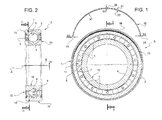
figure 1 shows a front elevation view, taken along a median plane perpendicular to the symmetry axis of a rolling bearing equipped with a creep prevention device made according to the invention with a component of the device shown both in assembly position and in exploded configuration, for greater clarity; -
figure 2 shows a longitudinal elevation view, shown in radial section taken along a plotting line II-II, of the rolling bearing infigure 1 ; -
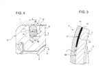
figure 3 shows a front elevation view on enlarged scale taken along a plotting line III-III of the rolling bearing infigures 1 and 2 ; and -
figure 4 shows a view in radial section and on further enlarged scale of a detail infigure 2 . - With reference to figures from 1 to 4, reference numeral 1 (
figure 4 ) as a whole shows a creep prevention device for aring 2 of a rollingbearing 3. - The rolling
bearing 3 has a symmetry axis A and comprises an outer ring, in the non-limiting embodiment in point constituted by thering 2, an inner ring 4, a plurality of revolvingbodies 5, balls in the case in point, arranged between theouter ring 2 and the inner ring 4 and engaged in respectiverolling tracks 6 and 7 of theouter ring 2 and the inner ring 4, respectively, and the creep prevention device 1, which is carried according to the invention by a first of the inner 4 and theouter ring 2 in contact in use with a seat 8 (figure 4 ) with respect to which thebearing 3 must remain stationary; in the illustrated case in point, the creep prevention device 1 is integrally carried by theouter ring 2, a lateral outerlateral assembly surface 10 of which is in contact in use with the seat 8. - The
rings 2 and 4 are concentric with respect to axis A and the creep prevention device 1 comprises at least oneannular groove 11 obtained on thelateral assembly surface 10 so as to obtain a radial shallow recess on the cylindricallateral surface 10. Preferably, theannular groove 11 is obtained near afront end 12 of thebearing 3; in a possible variant (not shown for the sake of simplicity) an identical annular groove may be obtained near afront end 13 of thebearing 3, opposite toend 12. - According to the invention, the creep prevention device 1 further comprises in combination, for each
annular groove 11 present on the ring 2: afirst element 15, shaped as a circumferentially opened ring (and thus defining a half ring or semi-annular element 15) and having a radial thickness S (i.e. measured in direction perpendicular to axis A) smaller than a radial depth P (figure 4 ) of theannular groove 11; and asecond element 16, shaped as a closed ring, which also engages theannular groove 11, within which the element orring 16 is radially mounted, superimposed on the first element orhalf ring 15 on the side thereof facing toward thelateral assembly surface 10. - According to an aspect of the invention, the
half ring 15 is entirely mounted within theannular groove 11, free to turn circumferentially in theannular groove 11, within a bottom portion 18 (figure 4 ) of theannular groove 11. - The closed
ring 16 has a constant radial thickness F, of measure such that, at least in correspondence with part of the first element orhalf ring 15, the second element orhalf ring 16 radially and overhangingly protrudes, at least in part, with respect to thelateral assembly surface 10, so that, at least in a circumferential spot of theannular groove 11, the sum of the thicknesses S and F is higher than the value of depth P (and thus the S + F > P ratio applies). - In the non-limiting example shown, the
lateral assembly surface 10 is the radially outer surface of theouter ring 2 of thebearing 3. It is however apparent for a person skilled in the art that the description above and the one that will follow can be applied, mutatis mutandis, also to the case in which the lateral assembly surface is a radially innerlateral surface 19 of the inner ring 4 and the seat 8 is thus defined by the lateral outer surface of a shaft or other mechanical cylindrical element. - The first element or
half ring 15 is defined by a circumference segment or stretch or piece of ring having a circumferential arc-of-a-circle profile and, according to an aspect of the invention, a non-constant radial thickness S such that when theelement 15 is mounted in theannular groove 11, theelement 15 is always arranged symmetrically with respect to a radial plane of the bearing ring (defined by plotting line II-II infigure 1 ) passing through the middle line (i.e. at the median circumferential point) of the element orhalf ring 15. - In particular, the element or
half ring 15 has a radial section of shape and dimensions complementary to those of thebottom portion 18 of the annular groove 11 (in the non-limiting case in point, essentially rectangular with rounded vertexes facing the side opposite to the surface 10) and is delimited by a lateral radiallyinner surface 20 and by a lateral radiallyouter surface 21. - The
lateral surface 20 is a cylindrical surface having a radius of curvature R identical to that of a bottom wall 22 (figures 3 and 4 ) of theannular groove 11, which bottom wall delimits thebottom portion 18 on the side opposite to thesurface 10; thelateral surface 21 is a curved surface having a continuously variable radius (in reduction) towards oppositecircumferential ends 23 and 24 of the element orhalf ring 15. - Therefore, the
element 15 has a maximum radial thickness S1 at amedian portion 25 thereof to gradually taper off, on the side of thelateral surface 21 and in a radial direction toward thebottom portion 18 of the annular groove 1, towards bothopposite ends 23 and 24 thereof, where a radial thickness S2 smaller than the thickness S1 is reached. Furthermore, according to a preferred aspect of the invention, the element orhalf ring 15 has a circumferential extension equal to less than a half of the circumferential extension of theannular groove 11, as clearly shown infigure 1 . - According to the invention, while the S1 + F > P ratio is always applicable, the sum of the radial thicknesses S2 and F may also be only equal to or lower than P; the element or closed
ring 16, thus, always protrudes radially from theannular groove 11 and with respect to thelateral surface 10 only at themedian portion 25 of thehalf ring 15. - According to a further important aspect of the invention, both the first and the
second element half ring 15 is made of a synthetic plastic material, so as to be elastically deformable and adapted to slide in practice within thegroove portion 11 with low friction, but be also provided with a given rigidity, while the second element or closedring 16 is made of an elastomeric or rubbery material and preferably consists of an o-ring. - According to a first possible embodiment of the invention, in combination with the above, the
annular groove 11 has a constant depth P measured in a radial direction and a constant width L measured in a direction parallel to symmetry axis A. Thus, the sum of the radial thicknesses S1 of theelement 15 and F of theelement 16 will be greater than the depth P only along a circumferential stretch of theannular grove 11 arranged in an angular position corresponding to that of themedian portion 25 of theelement 15, when theelement 15 is engaged in thegroove 11. - According to a preferred embodiment of the invention, however, the
annular groove 11 is eccentric parallelly to a median plane of the bearing ring, median plane which is perpendicular to the symmetry axis A of thering 2 of thebearing 3, and which infigure 2 is parallel to the plotting line III-III. Therefore, the symmetry axis of thegroove 11 will be an axis B (figure 2 ) parallel to axis A, but eccentric with respect to axis A, namely laterally spaced apart from axis A by a quantity E (eccentricity) and theannular groove 11 has, in diametrically opposite positions, a maximum depth Pmax and a minimum depth Pmin respectively, such that Pmax-Pmin = 2E. - In this case, while the
element 16 continues to have a constant radial thickness F in circumferential direction, thefirst element 15 has instead a variable radial thickness S in circumferential direction chosen so as to compensate for the eccentricity E of theannular groove 11 with respect to the axis A of thebearing ring 2. Therefore, according to this embodiment, thesecond element 16 protrudes in part (by a constant radial thickness F chosen so as to be just greater than the minimum radial thickness Pmin of the annular groove 11) radially overhanging from thelateral assembly surface 10 along the entire circumferential extension thereof. - By virtue of the described structure, and in particular of the combination of the two elements, such as element 15 (incomplete, tapered ring) and element 16 (complete rubbery, elastic ring) a very effective, marked creep prevention can be obtained also in presence of very
deep tracks 6,7 with minimum interference between seat 8 andring 16, which is mostly concentrated only on a very limited circumferential portion of thering 16. Furthermore, thehalf ring 15 exerts the "wedge" effect thereof more effectively if thehalf ring 16 is tapered at theends 23, 24 or/and if theannular groove 11 is obtained eccentrically with respect to axis A, which further improves the performance of the device 1.
Claims (10)
- A creep prevention device (1) for a ring (2) of a rolling bearing (3) comprising an annular groove (11) obtained on a lateral assembly surface (10) of a bearing ring (2) in contact in use with a seat (8) with respect to which the ring (2) must remain stationary; characterized in that it further comprises, in combination:- a first element (15), shaped as a ring opened circumferentially and having a radial thickness (S) smaller than a radial depth (P) of the annular groove, mounted within the annular groove (11) and free to move circumferentially within the annular groove (11); and- a second element (16), shaped as a closed ring, which engages the annular groove (11), within which it is radially mounted superimposed on the first element (15) on the side of the lateral assembly surface (10), and which has a constant radial thickness (F) such that the second element (16) protrudes in part in radial manner from the lateral assembly surface (10) at least at a portion (25) of the first element;- said first element being defined by a circumferential segment (15) of a ring having a circumferential arc-of-a-circle profile and a non-constant radial thickness (S) such that the first element (15) is symmetric with respect to a radial plane (II-II) of the bearing ring (2) when the first element (15) is mounted in the annular groove (11);- the first element (15) having a circumferential extension equal to less than a half of the circumferential extension of the annular groove (11).
- A device according to claim 1, characterized in that the shape and size of the radial section of the first element (15) are complementary with those of a bottom portion (18) of the annular groove (11) and in that the radial section has a maximum radial thickness (S1) at a middle portion (25) of the first element to gradually taper off, in a radial direction, on the side of the bottom portion (18) of the annular groove, towards opposite ends (23,24) thereof.
- A device according to one of the preceding claims, characterized in that both the first and the second element (15;16) are elastically deformable.
- A device according to one of the preceding claims, characterized in that the first element (15) is made of a synthetic plastic material, while the second element (16) is made of an elastomeric material.
- A device according to one of the preceding claims, characterized in that the second element (16) is an o-ring.
- A device according to one of the preceding claims, characterized in that the annular groove (11) has a constant depth (P), measured in a radial direction, and a constant width (L), measured in a direction parallel to a symmetry axis (A) of the bearing ring (2); the sum of the radial thicknesses of the first and the second element (15;16) along at least one circumferential stretch of the annular groove (11) being greater than the depth (P) in radial direction of the annular groove (11).
- A device according to one of the preceding claims, characterized in that the annular groove (11) is eccentric with respect to a symmetry axis (A) of the bearing ring.
- A device according to claim 7, characterized in that the second element (16) has a constant radial thickness (F) in a circumferential direction, while the first element (15) has a non-constant radial thickness (S) in the circumferential direction such as to compensate the eccentricity of the annular groove (11), and such that the second element (16) partially protrudes in radial manner from the lateral assembly surface (10) along the whole circumferential extension of the second element (16) itself.
- A rolling bearing (3) comprising an outer ring (2), an inner ring (4), a plurality of revolving bodies (5) arranged between the outer ring and in the inner ring and engaged in respective rolling tracks (6,7) of the outer and inner ring, and a creep prevention device (1) according to any one of the preceding claims carried by a first one (2) of the inner and outer rings (2,4) in contact in use with a seat (8) with respect to which the bearing must remain stationary.
- A bearing (3) according to claim 11, characterized in that the lateral assembly surface (10) is a radially outer surface of the outer ring (2).
Applications Claiming Priority (1)
| Application Number | Priority Date | Filing Date | Title |
|---|---|---|---|
| IT000918A ITTO20120918A1 (en) | 2012-10-17 | 2012-10-17 | ANTI-SLIP DEVICE FOR A ROLLING BEARING RING AND BEARING EQUIPPED WITH THE SAME |
Publications (2)
| Publication Number | Publication Date |
|---|---|
| EP2722546A1 true EP2722546A1 (en) | 2014-04-23 |
| EP2722546B1 EP2722546B1 (en) | 2016-01-20 |
Family
ID=47428902
Family Applications (1)
| Application Number | Title | Priority Date | Filing Date |
|---|---|---|---|
| EP13187970.2A Active EP2722546B1 (en) | 2012-10-17 | 2013-10-09 | Creep prevention device for a ring of a rolling bearing and bearing equipped therewith |
Country Status (5)
| Country | Link |
|---|---|
| US (1) | US9127714B2 (en) |
| EP (1) | EP2722546B1 (en) |
| JP (1) | JP2014081077A (en) |
| CN (1) | CN103775495B (en) |
| IT (1) | ITTO20120918A1 (en) |
Families Citing this family (2)
| Publication number | Priority date | Publication date | Assignee | Title |
|---|---|---|---|---|
| DE102014101645A1 (en) * | 2014-02-11 | 2015-08-13 | Getrag Getriebe- Und Zahnradfabrik Hermann Hagenmeyer Gmbh & Cie Kg | Axialsicherungsring, bearing assembly and manufacturing method thereof |
| JP7006227B2 (en) * | 2017-12-15 | 2022-01-24 | ヤマハ株式会社 | Operation device |
Citations (7)
| Publication number | Priority date | Publication date | Assignee | Title |
|---|---|---|---|---|
| DE7317297U (en) * | 1973-08-16 | Skf Kugellagerfabriken Gmbh | Fastening for roller bearing inner rings | |
| JP2000087988A (en) * | 1998-09-09 | 2000-03-28 | Nippon Seiko Kk | Anti-creep device for rolling bearings |
| EP1296077A2 (en) | 2001-09-25 | 2003-03-26 | SKF INDUSTRIE S.p.A. | Intermediate element for mounting a rolling bearing |
| JP2005042894A (en) * | 2003-07-25 | 2005-02-17 | Nsk Ltd | Double row rolling bearing device |
| DE202006008982U1 (en) * | 2005-06-06 | 2006-08-10 | Aktiebolaget Skf | Rotation blocking device for a rolling bearing with an outer stationary race comprises a rotation blocking ring with a tongue provided with at least one surface in contact with a cutout in the bearing seat |
| JP2011094727A (en) | 2009-10-30 | 2011-05-12 | Nsk Ltd | Creep prevention device for rolling bearing |
| JP2011247396A (en) | 2010-05-31 | 2011-12-08 | Nsk Ltd | Rolling device |
Family Cites Families (17)
| Publication number | Priority date | Publication date | Assignee | Title |
|---|---|---|---|---|
| US3007753A (en) * | 1957-05-15 | 1961-11-07 | Fafnir Bearing Co | Bearing lock |
| JPS4816409Y1 (en) * | 1969-12-09 | 1973-05-10 | ||
| JPS5614219U (en) * | 1979-07-13 | 1981-02-06 | ||
| US4511191A (en) * | 1984-02-14 | 1985-04-16 | Koyo Seike Company Limited | Anticreep device for annular member |
| DE3710185A1 (en) * | 1987-03-27 | 1988-10-13 | Skf Gmbh | Fixed bearing for a spindle which is installed in a housing and loaded in an axial direction |
| JPH1082428A (en) * | 1996-07-17 | 1998-03-31 | Nippon Seiko Kk | Anti-creep device for rolling bearings |
| JP2000130454A (en) * | 1998-10-23 | 2000-05-12 | Ntn Corp | Bearing device |
| FR2835580B1 (en) * | 2002-02-05 | 2004-07-09 | Skf Ab | ROLLING BEARING, ESPECIALLY FOR ELECTRIC MOTORS |
| JP2005048862A (en) * | 2003-07-28 | 2005-02-24 | Nsk Ltd | Rolling bearing |
| JP2008008408A (en) * | 2006-06-29 | 2008-01-17 | Ntn Corp | Creep preventive rolling bearing |
| US8388232B2 (en) * | 2007-01-11 | 2013-03-05 | Nsk Ltd. | Rolling bearing |
| JP2008256138A (en) * | 2007-04-06 | 2008-10-23 | Nsk Ltd | Bearing device |
| JP2008281154A (en) * | 2007-05-14 | 2008-11-20 | Ntn Corp | Creep prevention rolling bearing |
| JP4877135B2 (en) * | 2007-08-02 | 2012-02-15 | 日本精工株式会社 | Bearing device and method for assembling bearing device |
| JP5303240B2 (en) * | 2008-10-22 | 2013-10-02 | Ntn株式会社 | Rolling bearing and rotating shaft support structure |
| CN201615144U (en) * | 2010-02-10 | 2010-10-27 | 宁波达尔轴承有限公司 | Wriggle proofing bearing |
| JP5232266B2 (en) | 2011-04-21 | 2013-07-10 | 積水化学工業株式会社 | Power control system |
-
2012
- 2012-10-17 IT IT000918A patent/ITTO20120918A1/en unknown
-
2013
- 2013-10-09 EP EP13187970.2A patent/EP2722546B1/en active Active
- 2013-10-16 JP JP2013215319A patent/JP2014081077A/en active Pending
- 2013-10-17 CN CN201310757090.4A patent/CN103775495B/en active Active
- 2013-10-17 US US14/055,967 patent/US9127714B2/en active Active
Patent Citations (7)
| Publication number | Priority date | Publication date | Assignee | Title |
|---|---|---|---|---|
| DE7317297U (en) * | 1973-08-16 | Skf Kugellagerfabriken Gmbh | Fastening for roller bearing inner rings | |
| JP2000087988A (en) * | 1998-09-09 | 2000-03-28 | Nippon Seiko Kk | Anti-creep device for rolling bearings |
| EP1296077A2 (en) | 2001-09-25 | 2003-03-26 | SKF INDUSTRIE S.p.A. | Intermediate element for mounting a rolling bearing |
| JP2005042894A (en) * | 2003-07-25 | 2005-02-17 | Nsk Ltd | Double row rolling bearing device |
| DE202006008982U1 (en) * | 2005-06-06 | 2006-08-10 | Aktiebolaget Skf | Rotation blocking device for a rolling bearing with an outer stationary race comprises a rotation blocking ring with a tongue provided with at least one surface in contact with a cutout in the bearing seat |
| JP2011094727A (en) | 2009-10-30 | 2011-05-12 | Nsk Ltd | Creep prevention device for rolling bearing |
| JP2011247396A (en) | 2010-05-31 | 2011-12-08 | Nsk Ltd | Rolling device |
Also Published As
| Publication number | Publication date |
|---|---|
| US9127714B2 (en) | 2015-09-08 |
| JP2014081077A (en) | 2014-05-08 |
| ITTO20120918A1 (en) | 2014-04-18 |
| CN103775495A (en) | 2014-05-07 |
| EP2722546B1 (en) | 2016-01-20 |
| US20140105530A1 (en) | 2014-04-17 |
| CN103775495B (en) | 2017-07-07 |
Similar Documents
| Publication | Publication Date | Title |
|---|---|---|
| KR102459648B1 (en) | sliding parts | |
| RU2570240C1 (en) | Large rolling bearing | |
| US10054155B2 (en) | Ball bearing | |
| US9422983B2 (en) | Roller bearing with modular shoulders | |
| US10145459B2 (en) | Wave generator and strain wave gear device | |
| EP2994656B1 (en) | Spherical roller bearing cage with cylindrical guidance contact surfaces and inward flange turned radially outward | |
| US20160312823A1 (en) | Rolling-element bearing, high speed bearing and compressor | |
| JP2016516969A (en) | Grease lubricated angular contact ball bearings | |
| CN112969866B (en) | Unit type wave gear device | |
| EP2722546B1 (en) | Creep prevention device for a ring of a rolling bearing and bearing equipped therewith | |
| US3306687A (en) | Single row spherical bearing | |
| CN112610609A (en) | Sealing device with dynamic action, in particular for rolling bearings | |
| US10982715B2 (en) | Rotary table device | |
| US9097293B2 (en) | Mechanical system comprising a one-way clutch and alternator comprising such a system | |
| US20130022482A1 (en) | Non-circular bearing and a method for rotating a cam | |
| US20140248016A1 (en) | Composite annular seal assembly for bearings | |
| US20140034439A1 (en) | Mechanical system comprising a one-way clutch and alternator comprising such a system | |
| EP3565989B1 (en) | Seal | |
| US3843217A (en) | Antifriction bearing | |
| CN202165402U (en) | Semi-closed deep groove ball bearing | |
| US11982343B2 (en) | Strain wave gearing having roller-bearing-type wave generator | |
| CN104006071A (en) | Overall four-point contact ball bearing with seal | |
| EP3034899B1 (en) | Seal for self aligning roller bearing | |
| CN203979126U (en) | The whole four-point contact ball of band sealing | |
| CN208185237U (en) | A kind of outer ring annular knurl bearing |
Legal Events
| Date | Code | Title | Description |
|---|---|---|---|
| PUAI | Public reference made under article 153(3) epc to a published international application that has entered the european phase |
Free format text: ORIGINAL CODE: 0009012 |
|
| AK | Designated contracting states |
Kind code of ref document: A1 Designated state(s): AL AT BE BG CH CY CZ DE DK EE ES FI FR GB GR HR HU IE IS IT LI LT LU LV MC MK MT NL NO PL PT RO RS SE SI SK SM TR |
|
| AX | Request for extension of the european patent |
Extension state: BA ME |
|
| 17P | Request for examination filed |
Effective date: 20141204 |
|
| RBV | Designated contracting states (corrected) |
Designated state(s): AL AT BE BG CH CY CZ DE DK EE ES FI FR GB GR HR HU IE IS IT LI LT LU LV MC MK MT NL NO PL PT RO RS SE SI SK SM TR |
|
| REG | Reference to a national code |
Ref country code: DE Ref legal event code: R079 Ref document number: 602013004723 Country of ref document: DE Free format text: PREVIOUS MAIN CLASS: F16C0035070000 Ipc: F16C0033580000 |
|
| RIC1 | Information provided on ipc code assigned before grant |
Ipc: F16C 33/58 20060101AFI20150617BHEP Ipc: F16C 35/067 20060101ALI20150617BHEP Ipc: F16C 35/07 20060101ALI20150617BHEP |
|
| GRAP | Despatch of communication of intention to grant a patent |
Free format text: ORIGINAL CODE: EPIDOSNIGR1 |
|
| INTG | Intention to grant announced |
Effective date: 20150811 |
|
| GRAS | Grant fee paid |
Free format text: ORIGINAL CODE: EPIDOSNIGR3 |
|
| GRAA | (expected) grant |
Free format text: ORIGINAL CODE: 0009210 |
|
| AK | Designated contracting states |
Kind code of ref document: B1 Designated state(s): AL AT BE BG CH CY CZ DE DK EE ES FI FR GB GR HR HU IE IS IT LI LT LU LV MC MK MT NL NO PL PT RO RS SE SI SK SM TR |
|
| REG | Reference to a national code |
Ref country code: GB Ref legal event code: FG4D |
|
| REG | Reference to a national code |
Ref country code: CH Ref legal event code: EP |
|
| REG | Reference to a national code |
Ref country code: IE Ref legal event code: FG4D |
|
| REG | Reference to a national code |
Ref country code: AT Ref legal event code: REF Ref document number: 771878 Country of ref document: AT Kind code of ref document: T Effective date: 20160215 |
|
| REG | Reference to a national code |
Ref country code: DE Ref legal event code: R096 Ref document number: 602013004723 Country of ref document: DE |
|
| REG | Reference to a national code |
Ref country code: SE Ref legal event code: TRGR |
|
| REG | Reference to a national code |
Ref country code: LT Ref legal event code: MG4D Ref country code: NL Ref legal event code: MP Effective date: 20160120 |
|
| REG | Reference to a national code |
Ref country code: AT Ref legal event code: MK05 Ref document number: 771878 Country of ref document: AT Kind code of ref document: T Effective date: 20160120 |
|
| PG25 | Lapsed in a contracting state [announced via postgrant information from national office to epo] |
Ref country code: NL Free format text: LAPSE BECAUSE OF FAILURE TO SUBMIT A TRANSLATION OF THE DESCRIPTION OR TO PAY THE FEE WITHIN THE PRESCRIBED TIME-LIMIT Effective date: 20160120 |
|
| PG25 | Lapsed in a contracting state [announced via postgrant information from national office to epo] |
Ref country code: FI Free format text: LAPSE BECAUSE OF FAILURE TO SUBMIT A TRANSLATION OF THE DESCRIPTION OR TO PAY THE FEE WITHIN THE PRESCRIBED TIME-LIMIT Effective date: 20160120 Ref country code: ES Free format text: LAPSE BECAUSE OF FAILURE TO SUBMIT A TRANSLATION OF THE DESCRIPTION OR TO PAY THE FEE WITHIN THE PRESCRIBED TIME-LIMIT Effective date: 20160120 Ref country code: NO Free format text: LAPSE BECAUSE OF FAILURE TO SUBMIT A TRANSLATION OF THE DESCRIPTION OR TO PAY THE FEE WITHIN THE PRESCRIBED TIME-LIMIT Effective date: 20160420 Ref country code: HR Free format text: LAPSE BECAUSE OF FAILURE TO SUBMIT A TRANSLATION OF THE DESCRIPTION OR TO PAY THE FEE WITHIN THE PRESCRIBED TIME-LIMIT Effective date: 20160120 Ref country code: GR Free format text: LAPSE BECAUSE OF FAILURE TO SUBMIT A TRANSLATION OF THE DESCRIPTION OR TO PAY THE FEE WITHIN THE PRESCRIBED TIME-LIMIT Effective date: 20160421 |
|
| PG25 | Lapsed in a contracting state [announced via postgrant information from national office to epo] |
Ref country code: IS Free format text: LAPSE BECAUSE OF FAILURE TO SUBMIT A TRANSLATION OF THE DESCRIPTION OR TO PAY THE FEE WITHIN THE PRESCRIBED TIME-LIMIT Effective date: 20160520 Ref country code: PT Free format text: LAPSE BECAUSE OF FAILURE TO SUBMIT A TRANSLATION OF THE DESCRIPTION OR TO PAY THE FEE WITHIN THE PRESCRIBED TIME-LIMIT Effective date: 20160520 Ref country code: LT Free format text: LAPSE BECAUSE OF FAILURE TO SUBMIT A TRANSLATION OF THE DESCRIPTION OR TO PAY THE FEE WITHIN THE PRESCRIBED TIME-LIMIT Effective date: 20160120 Ref country code: AT Free format text: LAPSE BECAUSE OF FAILURE TO SUBMIT A TRANSLATION OF THE DESCRIPTION OR TO PAY THE FEE WITHIN THE PRESCRIBED TIME-LIMIT Effective date: 20160120 Ref country code: LV Free format text: LAPSE BECAUSE OF FAILURE TO SUBMIT A TRANSLATION OF THE DESCRIPTION OR TO PAY THE FEE WITHIN THE PRESCRIBED TIME-LIMIT Effective date: 20160120 Ref country code: RS Free format text: LAPSE BECAUSE OF FAILURE TO SUBMIT A TRANSLATION OF THE DESCRIPTION OR TO PAY THE FEE WITHIN THE PRESCRIBED TIME-LIMIT Effective date: 20160120 Ref country code: PL Free format text: LAPSE BECAUSE OF FAILURE TO SUBMIT A TRANSLATION OF THE DESCRIPTION OR TO PAY THE FEE WITHIN THE PRESCRIBED TIME-LIMIT Effective date: 20160120 |
|
| REG | Reference to a national code |
Ref country code: DE Ref legal event code: R097 Ref document number: 602013004723 Country of ref document: DE |
|
| REG | Reference to a national code |
Ref country code: FR Ref legal event code: PLFP Year of fee payment: 4 |
|
| PG25 | Lapsed in a contracting state [announced via postgrant information from national office to epo] |
Ref country code: DK Free format text: LAPSE BECAUSE OF FAILURE TO SUBMIT A TRANSLATION OF THE DESCRIPTION OR TO PAY THE FEE WITHIN THE PRESCRIBED TIME-LIMIT Effective date: 20160120 Ref country code: EE Free format text: LAPSE BECAUSE OF FAILURE TO SUBMIT A TRANSLATION OF THE DESCRIPTION OR TO PAY THE FEE WITHIN THE PRESCRIBED TIME-LIMIT Effective date: 20160120 |
|
| PLBE | No opposition filed within time limit |
Free format text: ORIGINAL CODE: 0009261 |
|
| STAA | Information on the status of an ep patent application or granted ep patent |
Free format text: STATUS: NO OPPOSITION FILED WITHIN TIME LIMIT |
|
| PG25 | Lapsed in a contracting state [announced via postgrant information from national office to epo] |
Ref country code: SM Free format text: LAPSE BECAUSE OF FAILURE TO SUBMIT A TRANSLATION OF THE DESCRIPTION OR TO PAY THE FEE WITHIN THE PRESCRIBED TIME-LIMIT Effective date: 20160120 Ref country code: CZ Free format text: LAPSE BECAUSE OF FAILURE TO SUBMIT A TRANSLATION OF THE DESCRIPTION OR TO PAY THE FEE WITHIN THE PRESCRIBED TIME-LIMIT Effective date: 20160120 Ref country code: RO Free format text: LAPSE BECAUSE OF FAILURE TO SUBMIT A TRANSLATION OF THE DESCRIPTION OR TO PAY THE FEE WITHIN THE PRESCRIBED TIME-LIMIT Effective date: 20160120 Ref country code: SK Free format text: LAPSE BECAUSE OF FAILURE TO SUBMIT A TRANSLATION OF THE DESCRIPTION OR TO PAY THE FEE WITHIN THE PRESCRIBED TIME-LIMIT Effective date: 20160120 |
|
| 26N | No opposition filed |
Effective date: 20161021 |
|
| PG25 | Lapsed in a contracting state [announced via postgrant information from national office to epo] |
Ref country code: BE Free format text: LAPSE BECAUSE OF FAILURE TO SUBMIT A TRANSLATION OF THE DESCRIPTION OR TO PAY THE FEE WITHIN THE PRESCRIBED TIME-LIMIT Effective date: 20160120 |
|
| PG25 | Lapsed in a contracting state [announced via postgrant information from national office to epo] |
Ref country code: SI Free format text: LAPSE BECAUSE OF FAILURE TO SUBMIT A TRANSLATION OF THE DESCRIPTION OR TO PAY THE FEE WITHIN THE PRESCRIBED TIME-LIMIT Effective date: 20160120 Ref country code: BG Free format text: LAPSE BECAUSE OF FAILURE TO SUBMIT A TRANSLATION OF THE DESCRIPTION OR TO PAY THE FEE WITHIN THE PRESCRIBED TIME-LIMIT Effective date: 20160420 |
|
| REG | Reference to a national code |
Ref country code: CH Ref legal event code: PL |
|
| REG | Reference to a national code |
Ref country code: IE Ref legal event code: MM4A |
|
| PG25 | Lapsed in a contracting state [announced via postgrant information from national office to epo] |
Ref country code: LI Free format text: LAPSE BECAUSE OF NON-PAYMENT OF DUE FEES Effective date: 20161031 Ref country code: CH Free format text: LAPSE BECAUSE OF NON-PAYMENT OF DUE FEES Effective date: 20161031 |
|
| PG25 | Lapsed in a contracting state [announced via postgrant information from national office to epo] |
Ref country code: LU Free format text: LAPSE BECAUSE OF NON-PAYMENT OF DUE FEES Effective date: 20161009 |
|
| REG | Reference to a national code |
Ref country code: FR Ref legal event code: PLFP Year of fee payment: 5 |
|
| PG25 | Lapsed in a contracting state [announced via postgrant information from national office to epo] |
Ref country code: IE Free format text: LAPSE BECAUSE OF NON-PAYMENT OF DUE FEES Effective date: 20161009 |
|
| PG25 | Lapsed in a contracting state [announced via postgrant information from national office to epo] |
Ref country code: CY Free format text: LAPSE BECAUSE OF FAILURE TO SUBMIT A TRANSLATION OF THE DESCRIPTION OR TO PAY THE FEE WITHIN THE PRESCRIBED TIME-LIMIT Effective date: 20160120 Ref country code: HU Free format text: LAPSE BECAUSE OF FAILURE TO SUBMIT A TRANSLATION OF THE DESCRIPTION OR TO PAY THE FEE WITHIN THE PRESCRIBED TIME-LIMIT; INVALID AB INITIO Effective date: 20131009 |
|
| PG25 | Lapsed in a contracting state [announced via postgrant information from national office to epo] |
Ref country code: MC Free format text: LAPSE BECAUSE OF FAILURE TO SUBMIT A TRANSLATION OF THE DESCRIPTION OR TO PAY THE FEE WITHIN THE PRESCRIBED TIME-LIMIT Effective date: 20160120 Ref country code: MK Free format text: LAPSE BECAUSE OF FAILURE TO SUBMIT A TRANSLATION OF THE DESCRIPTION OR TO PAY THE FEE WITHIN THE PRESCRIBED TIME-LIMIT Effective date: 20160120 Ref country code: MT Free format text: LAPSE BECAUSE OF NON-PAYMENT OF DUE FEES Effective date: 20161031 |
|
| REG | Reference to a national code |
Ref country code: FR Ref legal event code: PLFP Year of fee payment: 6 |
|
| PG25 | Lapsed in a contracting state [announced via postgrant information from national office to epo] |
Ref country code: AL Free format text: LAPSE BECAUSE OF FAILURE TO SUBMIT A TRANSLATION OF THE DESCRIPTION OR TO PAY THE FEE WITHIN THE PRESCRIBED TIME-LIMIT Effective date: 20160120 Ref country code: TR Free format text: LAPSE BECAUSE OF FAILURE TO SUBMIT A TRANSLATION OF THE DESCRIPTION OR TO PAY THE FEE WITHIN THE PRESCRIBED TIME-LIMIT Effective date: 20160120 |
|
| PGFP | Annual fee paid to national office [announced via postgrant information from national office to epo] |
Ref country code: GB Payment date: 20191029 Year of fee payment: 7 |
|
| GBPC | Gb: european patent ceased through non-payment of renewal fee |
Effective date: 20201009 |
|
| PG25 | Lapsed in a contracting state [announced via postgrant information from national office to epo] |
Ref country code: GB Free format text: LAPSE BECAUSE OF NON-PAYMENT OF DUE FEES Effective date: 20201009 |
|
| P01 | Opt-out of the competence of the unified patent court (upc) registered |
Effective date: 20230513 |
|
| PGFP | Annual fee paid to national office [announced via postgrant information from national office to epo] |
Ref country code: DE Payment date: 20251028 Year of fee payment: 13 |
|
| PGFP | Annual fee paid to national office [announced via postgrant information from national office to epo] |
Ref country code: IT Payment date: 20251022 Year of fee payment: 13 |
|
| PGFP | Annual fee paid to national office [announced via postgrant information from national office to epo] |
Ref country code: FR Payment date: 20251027 Year of fee payment: 13 |
|
| PGFP | Annual fee paid to national office [announced via postgrant information from national office to epo] |
Ref country code: SE Payment date: 20251024 Year of fee payment: 13 |