EP1296077A2 - Intermediate element for mounting a rolling bearing - Google Patents
Intermediate element for mounting a rolling bearing Download PDFInfo
- Publication number
- EP1296077A2 EP1296077A2 EP02021009A EP02021009A EP1296077A2 EP 1296077 A2 EP1296077 A2 EP 1296077A2 EP 02021009 A EP02021009 A EP 02021009A EP 02021009 A EP02021009 A EP 02021009A EP 1296077 A2 EP1296077 A2 EP 1296077A2
- Authority
- EP
- European Patent Office
- Prior art keywords
- annular element
- groove
- element according
- cylindrical surface
- around
- Prior art date
- Legal status (The legal status is an assumption and is not a legal conclusion. Google has not performed a legal analysis and makes no representation as to the accuracy of the status listed.)
- Granted
Links
- 238000005096 rolling process Methods 0.000 title claims abstract description 7
- 229920003023 plastic Polymers 0.000 claims abstract description 23
- 239000004033 plastic Substances 0.000 claims abstract description 23
- 239000000463 material Substances 0.000 claims abstract description 8
- 230000000295 complement effect Effects 0.000 claims abstract description 4
- 229910000831 Steel Inorganic materials 0.000 description 3
- 230000000694 effects Effects 0.000 description 3
- 239000010959 steel Substances 0.000 description 3
- 238000005406 washing Methods 0.000 description 3
- 230000001419 dependent effect Effects 0.000 description 1
- 230000014509 gene expression Effects 0.000 description 1
- 238000000465 moulding Methods 0.000 description 1
Images

Classifications
-
- D—TEXTILES; PAPER
- D06—TREATMENT OF TEXTILES OR THE LIKE; LAUNDERING; FLEXIBLE MATERIALS NOT OTHERWISE PROVIDED FOR
- D06F—LAUNDERING, DRYING, IRONING, PRESSING OR FOLDING TEXTILE ARTICLES
- D06F37/00—Details specific to washing machines covered by groups D06F21/00 - D06F25/00
-
- F—MECHANICAL ENGINEERING; LIGHTING; HEATING; WEAPONS; BLASTING
- F16—ENGINEERING ELEMENTS AND UNITS; GENERAL MEASURES FOR PRODUCING AND MAINTAINING EFFECTIVE FUNCTIONING OF MACHINES OR INSTALLATIONS; THERMAL INSULATION IN GENERAL
- F16C—SHAFTS; FLEXIBLE SHAFTS; ELEMENTS OR CRANKSHAFT MECHANISMS; ROTARY BODIES OTHER THAN GEARING ELEMENTS; BEARINGS
- F16C27/00—Elastic or yielding bearings or bearing supports, for exclusively rotary movement
- F16C27/06—Elastic or yielding bearings or bearing supports, for exclusively rotary movement by means of parts of rubber or like materials
- F16C27/066—Ball or roller bearings
-
- F—MECHANICAL ENGINEERING; LIGHTING; HEATING; WEAPONS; BLASTING
- F16—ENGINEERING ELEMENTS AND UNITS; GENERAL MEASURES FOR PRODUCING AND MAINTAINING EFFECTIVE FUNCTIONING OF MACHINES OR INSTALLATIONS; THERMAL INSULATION IN GENERAL
- F16C—SHAFTS; FLEXIBLE SHAFTS; ELEMENTS OR CRANKSHAFT MECHANISMS; ROTARY BODIES OTHER THAN GEARING ELEMENTS; BEARINGS
- F16C35/00—Rigid support of bearing units; Housings, e.g. caps, covers
- F16C35/04—Rigid support of bearing units; Housings, e.g. caps, covers in the case of ball or roller bearings
- F16C35/06—Mounting or dismounting of ball or roller bearings; Fixing them onto shaft or in housing
- F16C35/063—Fixing them on the shaft
-
- F—MECHANICAL ENGINEERING; LIGHTING; HEATING; WEAPONS; BLASTING
- F16—ENGINEERING ELEMENTS AND UNITS; GENERAL MEASURES FOR PRODUCING AND MAINTAINING EFFECTIVE FUNCTIONING OF MACHINES OR INSTALLATIONS; THERMAL INSULATION IN GENERAL
- F16C—SHAFTS; FLEXIBLE SHAFTS; ELEMENTS OR CRANKSHAFT MECHANISMS; ROTARY BODIES OTHER THAN GEARING ELEMENTS; BEARINGS
- F16C35/00—Rigid support of bearing units; Housings, e.g. caps, covers
- F16C35/04—Rigid support of bearing units; Housings, e.g. caps, covers in the case of ball or roller bearings
- F16C35/06—Mounting or dismounting of ball or roller bearings; Fixing them onto shaft or in housing
- F16C35/067—Fixing them in a housing
-
- F—MECHANICAL ENGINEERING; LIGHTING; HEATING; WEAPONS; BLASTING
- F16—ENGINEERING ELEMENTS AND UNITS; GENERAL MEASURES FOR PRODUCING AND MAINTAINING EFFECTIVE FUNCTIONING OF MACHINES OR INSTALLATIONS; THERMAL INSULATION IN GENERAL
- F16C—SHAFTS; FLEXIBLE SHAFTS; ELEMENTS OR CRANKSHAFT MECHANISMS; ROTARY BODIES OTHER THAN GEARING ELEMENTS; BEARINGS
- F16C19/00—Bearings with rolling contact, for exclusively rotary movement
- F16C19/02—Bearings with rolling contact, for exclusively rotary movement with bearing balls essentially of the same size in one or more circular rows
- F16C19/04—Bearings with rolling contact, for exclusively rotary movement with bearing balls essentially of the same size in one or more circular rows for radial load mainly
- F16C19/06—Bearings with rolling contact, for exclusively rotary movement with bearing balls essentially of the same size in one or more circular rows for radial load mainly with a single row or balls
-
- F—MECHANICAL ENGINEERING; LIGHTING; HEATING; WEAPONS; BLASTING
- F16—ENGINEERING ELEMENTS AND UNITS; GENERAL MEASURES FOR PRODUCING AND MAINTAINING EFFECTIVE FUNCTIONING OF MACHINES OR INSTALLATIONS; THERMAL INSULATION IN GENERAL
- F16C—SHAFTS; FLEXIBLE SHAFTS; ELEMENTS OR CRANKSHAFT MECHANISMS; ROTARY BODIES OTHER THAN GEARING ELEMENTS; BEARINGS
- F16C2226/00—Joining parts; Fastening; Assembling or mounting parts
- F16C2226/30—Material joints
-
- F—MECHANICAL ENGINEERING; LIGHTING; HEATING; WEAPONS; BLASTING
- F16—ENGINEERING ELEMENTS AND UNITS; GENERAL MEASURES FOR PRODUCING AND MAINTAINING EFFECTIVE FUNCTIONING OF MACHINES OR INSTALLATIONS; THERMAL INSULATION IN GENERAL
- F16C—SHAFTS; FLEXIBLE SHAFTS; ELEMENTS OR CRANKSHAFT MECHANISMS; ROTARY BODIES OTHER THAN GEARING ELEMENTS; BEARINGS
- F16C2340/00—Apparatus for treating textiles
-
- F—MECHANICAL ENGINEERING; LIGHTING; HEATING; WEAPONS; BLASTING
- F16—ENGINEERING ELEMENTS AND UNITS; GENERAL MEASURES FOR PRODUCING AND MAINTAINING EFFECTIVE FUNCTIONING OF MACHINES OR INSTALLATIONS; THERMAL INSULATION IN GENERAL
- F16C—SHAFTS; FLEXIBLE SHAFTS; ELEMENTS OR CRANKSHAFT MECHANISMS; ROTARY BODIES OTHER THAN GEARING ELEMENTS; BEARINGS
- F16C33/00—Parts of bearings; Special methods for making bearings or parts thereof
- F16C33/30—Parts of ball or roller bearings
- F16C33/58—Raceways; Race rings
- F16C33/583—Details of specific parts of races
- F16C33/586—Details of specific parts of races outside the space between the races, e.g. end faces or bore of inner ring
-
- Y—GENERAL TAGGING OF NEW TECHNOLOGICAL DEVELOPMENTS; GENERAL TAGGING OF CROSS-SECTIONAL TECHNOLOGIES SPANNING OVER SEVERAL SECTIONS OF THE IPC; TECHNICAL SUBJECTS COVERED BY FORMER USPC CROSS-REFERENCE ART COLLECTIONS [XRACs] AND DIGESTS
- Y10—TECHNICAL SUBJECTS COVERED BY FORMER USPC
- Y10S—TECHNICAL SUBJECTS COVERED BY FORMER USPC CROSS-REFERENCE ART COLLECTIONS [XRACs] AND DIGESTS
- Y10S384/00—Bearings
- Y10S384/90—Cooling or heating
- Y10S384/903—Retaining ring
Definitions
- the present invention relates to an annular element for a rolling bearing, of the type comprising a cylindrical surface in which a groove having a radial depth which is variable around the circumference of the cylindrical surface is formed, the surface being suitable for being over-moulded with a plastics material to form a body which is fixed for rotation with the annular element and has a plastics projection complementary with the groove and suitable for cooperating with the groove to prevent relative rotation between the annular element and the plastics body.
- Annular elements of the above-mentioned type are known, for example, from EP-A-0 972 958, US-A-3832024, and US-A-4925322. These publications describe bearings having rings which have eccentric grooves with rectangular axial sections.
- a disadvantage which arises when a plastics body is moulded over an annular element of a rolling bearing is due to the fact that, because of the different coefficients of thermal expansion of steel and plastics, the plastics body tends to rotate slowly relative to the ring of the bearing; this phenomenon is known by the term "creeping".
- the relative rotation between the plastics and the steel of the bearing causes rapid wear of the plastics due to friction so that the assembly becomes noisy and is inevitably subject to excessive vibrations and breakage.
- a general object of the present invention is to provide an annular element of the above-mentioned type which more effectively prevents relative rotation between the annular element and the plastics body moulded over it.
- a particular object of the invention is to provide an annular element for a rolling bearing which is suitable for supporting a rotating shaft of a drum in a washing machine without incurring the problems mentioned above, and which is specifically adapted to prevent the vibrations caused by the rotation of the drum from reaching unacceptable values.
- annular element 10 constituting the radially outer ring of a rolling bearing is indicated 10.
- the annular element 10 has an outer cylindrical surface 11 and a raceway 12 on its inner surface.
- a body P of plastics material is moulded over the outer cylindrical surface 11 and constitutes a fixed housing for supporting the bearing.
- the plastics body P may be a support element mounted in a washing machine for supporting rotatably, by means of the bearing, a rotary shaft on which the drum of the washing machine is fixed.
- the annular element 10 may be used for a bearing over which a pulley of plastics material is moulded, in particular for use as a belt tensioner in motor-vehicle engines.
- a radial groove 13 which is eccentric with respect to the central axis x of the element 10 (with an eccentricity "e” indicated in Figure 1) is formed in the outer surface 11 of the annular element 10 by means of a simple turning operation.
- the groove 13 has a substantially V-shaped cross-section with two opposed lateral walls or surfaces 13a, 13b diverging from the base 13c of the groove towards the cylindrical surface 11. Should the annular element tend to rotate relative to the body P in which it is housed, the projection F will be wedged between the surfaces 13a and 13b which will cooperate with the projection F to prevent relative rotation between the body P and the annular element 10.
- Figures 4 and 5 show schematically, purely by way of example, further alternative embodiments of the invention.
- the groove 13 has a substantially isosceles trapezoidal cross-section
- in Figure 5 it has a substantially right-angled trapezoidal cross-section.
- the groove 13 is preferably formed in a lateral region in which the ring is quite thick and not in the region of the maximum diameter of the raceway 12 in which, on the contrary, the radial thickness is least.
- the groove 13 may have a diameter considerably less than that of the cylindrical surface 11, as in the embodiment shown in Figures 1 and 2, so as to extend continuously around the circumference of the ring.
- the groove 13 extends merely along a circumferential arc so as to reach the surface tangentially at a point or along a sector of the outer surface 11, in any case achieving a form fit with results equivalent to those offered by the other embodiments described herein.
- two grooves 13 are provided, spaced apart axially and preferably angularly offset relative to one another in order further to improve the rotational locking effect of the annular element 10 relative to the body P in both senses of rotation.
- Figure 9 shows a further different embodiment of the invention in which the annular element 10 is a radially inner ring of a bearing with an inner cylindrical surface 11 which has an eccentric groove 13 having the characteristics described above with reference to any one of Figures 1 to 8.
- a plastics body P is over-moulded on the inside of the surface 11, producing a projection F extending radially outwards.
Landscapes
- Engineering & Computer Science (AREA)
- General Engineering & Computer Science (AREA)
- Mechanical Engineering (AREA)
- Textile Engineering (AREA)
- Rolling Contact Bearings (AREA)
- Support Of The Bearing (AREA)
Abstract
Description
- The present invention relates to an annular element for a rolling bearing, of the type comprising a cylindrical surface in which a groove having a radial depth which is variable around the circumference of the cylindrical surface is formed, the surface being suitable for being over-moulded with a plastics material to form a body which is fixed for rotation with the annular element and has a plastics projection complementary with the groove and suitable for cooperating with the groove to prevent relative rotation between the annular element and the plastics body.
- Annular elements of the above-mentioned type are known, for example, from EP-A-0 972 958, US-A-3832024, and US-A-4925322. These publications describe bearings having rings which have eccentric grooves with rectangular axial sections.
- A disadvantage which arises when a plastics body is moulded over an annular element of a rolling bearing is due to the fact that, because of the different coefficients of thermal expansion of steel and plastics, the plastics body tends to rotate slowly relative to the ring of the bearing; this phenomenon is known by the term "creeping". The relative rotation between the plastics and the steel of the bearing causes rapid wear of the plastics due to friction so that the assembly becomes noisy and is inevitably subject to excessive vibrations and breakage.
- A general object of the present invention is to provide an annular element of the above-mentioned type which more effectively prevents relative rotation between the annular element and the plastics body moulded over it.
- A particular object of the invention is to provide an annular element for a rolling bearing which is suitable for supporting a rotating shaft of a drum in a washing machine without incurring the problems mentioned above, and which is specifically adapted to prevent the vibrations caused by the rotation of the drum from reaching unacceptable values.
- These objects are achieved, according to the present invention, by an annular element having the characteristics set out in Claim 1. Preferred embodiments of the invention are defined in the dependent claims.
- Some preferred embodiments of the invention will now be described, purely by way of non-limiting example, with reference to the appended drawings, in which:
- Figure 1 is a side view of a bearing element according to the present invention,
- Figure 2 is an axially-sectioned partial view showing, on an enlarged scale, the bearing element of Figure 1 over which a plastics body is moulded,
- Figure 3 is an enlarged view of the detail indicated A in Figure 2,
- Figures 4 and 5 are views similar to Figure 3 which show a further two variants of the invention,
- Figure 6 is an axially-sectioned partial view similar to Figure 2 which shows a complete bearing over the outer ring of which a plastics body is moulded,
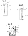
- Figures 7 and 8 are views similar to Figure 1, showing two further embodiments of the invention, and
- Figure 9 is an axially-sectioned partial view which shows a bearing over the inner ring of which a plastics body is moulded.
-
- With reference initially to Figure 1, an annular element constituting the radially outer ring of a rolling bearing is indicated 10. The
annular element 10 has an outercylindrical surface 11 and araceway 12 on its inner surface. - Throughout the present description and in the claims, terms and expressions indicating positions and orientations (such as "radial", axial", "inner, "outer") are intended to relate to the central axis x of the
annular element 10. - As shown in Figures 2 and 6, a body P of plastics material is moulded over the outer
cylindrical surface 11 and constitutes a fixed housing for supporting the bearing. The plastics body P may be a support element mounted in a washing machine for supporting rotatably, by means of the bearing, a rotary shaft on which the drum of the washing machine is fixed. Naturally, the reference to this possible field of application should not be interpreted as in any way limiting of the scope of the patent. For example, theannular element 10 may be used for a bearing over which a pulley of plastics material is moulded, in particular for use as a belt tensioner in motor-vehicle engines. - A
radial groove 13 which is eccentric with respect to the central axis x of the element 10 (with an eccentricity "e" indicated in Figure 1) is formed in theouter surface 11 of theannular element 10 by means of a simple turning operation. - The over-moulding of the plastics material which constitutes the outer body P produces a circumferential projection F of plastics material which extends radially inwardly and is complementary with the
groove 13. A form fit is thus created which locks the outer body P and theannular element 10 of the bearing together firmly, preventing their relative rotation in a circumferential direction. In fact, if, after some time, the plastics material moulded over the bearing no longer adheres to the steel of theouter ring 10 of the bearing, the eccentric projection F will press tangentially against thegroove 13 so that relative rotation between the outerannular element 10 of the bearing and the outer body P will be prevented. - An important characteristic of the present invention is that the axial width of the
groove 13 varies around its circumference, as shown in Figure 1. - With reference to Figure 3, the
groove 13 has a substantially V-shaped cross-section with two opposed lateral walls orsurfaces base 13c of the groove towards thecylindrical surface 11. Should the annular element tend to rotate relative to the body P in which it is housed, the projection F will be wedged between thesurfaces annular element 10. - This effect is additional to the locking effect achieved by the eccentricity of the groove, considerably improving effectiveness in comparison with the conventional solutions discussed in the introductory part of the present description which, instead, have an eccentric groove with a rectangular cross-section the lateral surfaces of which do not contribute to the locking.
- Figures 4 and 5 show schematically, purely by way of example, further alternative embodiments of the invention. In Figure 4, the
groove 13 has a substantially isosceles trapezoidal cross-section, and in Figure 5 it has a substantially right-angled trapezoidal cross-section. - Naturally, persons skilled in the art will also be able to identify other shapes (for example, round) for the cross-section of the
groove 13, which are equivalent to those described herein and are characterized by a variation both of the axial width and of the radial depth of the groove around its circumference. - With reference now to Figures 1 and 2, in order not to weaken the
ring 10, thegroove 13 is preferably formed in a lateral region in which the ring is quite thick and not in the region of the maximum diameter of theraceway 12 in which, on the contrary, the radial thickness is least. - The
groove 13 may have a diameter considerably less than that of thecylindrical surface 11, as in the embodiment shown in Figures 1 and 2, so as to extend continuously around the circumference of the ring. - In the variant shown in Figure 7, the
groove 13 extends merely along a circumferential arc so as to reach the surface tangentially at a point or along a sector of theouter surface 11, in any case achieving a form fit with results equivalent to those offered by the other embodiments described herein. - In the embodiment of Figure 8, two
grooves 13 are provided, spaced apart axially and preferably angularly offset relative to one another in order further to improve the rotational locking effect of theannular element 10 relative to the body P in both senses of rotation. - Finally, Figure 9 shows a further different embodiment of the invention in which the
annular element 10 is a radially inner ring of a bearing with an innercylindrical surface 11 which has aneccentric groove 13 having the characteristics described above with reference to any one of Figures 1 to 8. In Figure 9, a plastics body P is over-moulded on the inside of thesurface 11, producing a projection F extending radially outwards.
Claims (13)
- An annular element (10) for a rolling bearing, comprising a cylindrical surface (11) in which at least one groove (13) having a radial depth which is variable around the circumference of the cylindrical surface is formed, the surface being suitable for being over-moulded with a plastics material to form a body (P) which is fixed firmly for rotation with the annular element (10) and has at least one plastics projection (F) complementary with the groove (13) and suitable for cooperating with the groove to prevent relative rotation between the annular element (10) and the body (P),
characterized in that the axial width of the groove (13) varies around the circumference. - An annular element according to Claim 1, characterized in that the groove (13) has two opposed lateral surfaces (13a, 13b) diverging from the base (13c) of the groove (13) towards the cylindrical surface (11).
- An annular element according to Claim 1 or Claim 2, characterized in that the groove (13) is eccentric with respect to the axis (x) of the cylindrical surface (11).
- An annular element according to any one of Claims 1, 2 and 3, characterized in that the groove (13) has a substantially V-shaped cross-section.
- An annular element according to any one of Claims 1, 2 and 3, characterized in that the groove (13) has a substantially isosceles trapezoidal cross-section.
- An annular element according to any one of Claims 1, 2 and 3, characterized in that the groove (13) has a substantially right-angled trapezoidal cross-section.
- An annular element according to any one of the preceding claims, characterized in that the groove (13) is offset axially relative to the regions of minimum radial thickness in which the annular element (10) has raceways (12).
- An annular element according to any one of the preceding claims, characterized in that it comprises two axially spaced-apart grooves (13), the axial widths of which vary around the circumference.
- An annular element according to Claim 8, characterized in that the two grooves (13) are angularly offset relative to one another.
- An annular element according to Claim 1, characterized in that the annular element (10) is a radially outer ring of a bearing and in that the at least one groove (13) is formed in the outer cylindrical surface (11) of the annular element (10).
- An annular element according to Claim 1, characterized in that the annular element (10) is a radially inner ring of a bearing and in that the at least one groove (13) is formed in the inner cylindrical surface (11) of the annular element (10).
- An annular element according to Claim 1, characterized in that the groove (13) extends continuously around the cylindrical surface (11).
- An annular element according to Claim 1, characterized in that the eccentric groove (13) extends around a circumferential arc of the cylindrical surface (11).
Applications Claiming Priority (2)
| Application Number | Priority Date | Filing Date | Title |
|---|---|---|---|
| ITTO20010913 | 2001-09-25 | ||
| IT2001TO000913A ITTO20010913A1 (en) | 2001-09-25 | 2001-09-25 | ANNULAR ELEMENT FOR A ROLLING BEARING. |
Publications (3)
| Publication Number | Publication Date |
|---|---|
| EP1296077A2 true EP1296077A2 (en) | 2003-03-26 |
| EP1296077A3 EP1296077A3 (en) | 2004-11-17 |
| EP1296077B1 EP1296077B1 (en) | 2006-03-01 |
Family
ID=11459219
Family Applications (1)
| Application Number | Title | Priority Date | Filing Date |
|---|---|---|---|
| EP02021009A Expired - Lifetime EP1296077B1 (en) | 2001-09-25 | 2002-09-20 | An annular element for a rolling bearing |
Country Status (5)
| Country | Link |
|---|---|
| US (1) | US6715925B2 (en) |
| EP (1) | EP1296077B1 (en) |
| CN (1) | CN1267654C (en) |
| DE (1) | DE60209414T2 (en) |
| IT (1) | ITTO20010913A1 (en) |
Cited By (4)
| Publication number | Priority date | Publication date | Assignee | Title |
|---|---|---|---|---|
| EP1767684A1 (en) | 2005-09-27 | 2007-03-28 | Aktiebolaget SKF | Support for a rolling contact bearing holder for a washing machine |
| WO2007138029A1 (en) * | 2006-05-31 | 2007-12-06 | Vorwerk & Co. Interholding Gmbh | Method for securing ball bearings, and a module component as an example of a food processor with a shaft |
| EP1881100A1 (en) * | 2006-07-17 | 2008-01-23 | Aktiebolaget SKF | Bearing housing for a washing machine tub |
| EP2722546A1 (en) | 2012-10-17 | 2014-04-23 | Aktiebolaget SKF | Creep prevention device for a ring of a rolling bearing and bearing equipped therewith |
Families Citing this family (35)
| Publication number | Priority date | Publication date | Assignee | Title |
|---|---|---|---|---|
| US6935849B2 (en) * | 2003-10-16 | 2005-08-30 | Honeywell International, Inc. | Grooved shaft member and associated turbocharger and method |
| US7645204B2 (en) * | 2005-09-28 | 2010-01-12 | Dayco Products, Llc | Pulley assembly for maintaining constant position of a bearing outer race relative to a pulley, and method |
| ITTO20050868A1 (en) * | 2005-12-14 | 2007-06-15 | Skf Ab | BEARING HOLDER SUPPORT FOR WASHING MACHINES. |
| JP4807202B2 (en) * | 2006-09-15 | 2011-11-02 | 株式会社デンソー | Rotating base member |
| US7648179B2 (en) * | 2007-01-17 | 2010-01-19 | Halliburton Energy Services, Inc. | Connector having offset radius grooves |
| DE102008037786A1 (en) * | 2007-09-18 | 2009-03-26 | Schaeffler Kg | Uniform center support for bearing subassembly for use in propel shaft or drive shaft, has plastic-bearing housing for bearing and plastic-support insert for support |
| ITBO20080171A1 (en) * | 2008-03-17 | 2009-09-18 | Minganti International Ltd | PROCEDURE FOR THE PRODUCTION OF HUBS-WHEEL FOR VEHICLES AND HUB-WHEELS MADE WITH THIS PROCEDURE. |
| US8122782B2 (en) * | 2008-09-03 | 2012-02-28 | GM Global Technology Operations LLC | Pinion shaft and bearing assembly |
| DE102009041081B4 (en) * | 2008-10-08 | 2021-09-09 | Heidelberger Druckmaschinen Intellectual Property Ag & Co. Kg | Printing press |
| WO2010063299A1 (en) * | 2008-12-02 | 2010-06-10 | Ab Skf | Bearing unit |
| DE102009031063A1 (en) * | 2009-06-30 | 2011-01-05 | Schaeffler Technologies Gmbh & Co. Kg | roller bearing assembly |
| CN201490811U (en) * | 2009-08-05 | 2010-05-26 | 德昌电机(深圳)有限公司 | Automatic automobile gearbox and motor thereof |
| IT1399562B1 (en) * | 2010-04-15 | 2013-04-19 | Skf Ab | FLANGED BEARING RING FOR A BEARING UNIT OF THE WHEEL OF A MOTOR VEHICLE |
| IT1400320B1 (en) * | 2010-04-15 | 2013-05-24 | Skf Ab | FLANGED BEARING RING FOR A BEARING UNIT OF THE WHEEL OF A MOTOR VEHICLE |
| DE102010051840A1 (en) * | 2010-11-18 | 2012-05-24 | Schaeffler Technologies Gmbh & Co. Kg | bearing ring |
| JP5282126B2 (en) * | 2011-07-11 | 2013-09-04 | 日信工業株式会社 | Motor pump equipment |
| CN102825975A (en) * | 2012-09-18 | 2012-12-19 | 安徽安凯福田曙光车桥有限公司 | Structure for preventing outer race of bearing in hub from rotating |
| ITTO20130772A1 (en) * | 2013-09-25 | 2015-03-26 | Skf Ab | FLANGED RADIAL BEARING WITH VOLTAGE BODIES |
| JP6318555B2 (en) * | 2013-11-08 | 2018-05-09 | 日本精工株式会社 | Bearing device and bearing device manufacturing method |
| US9845860B2 (en) * | 2015-07-20 | 2017-12-19 | Dayco Ip Holdings, Llc | Retaining clamp for molded plastics |
| SE541296C2 (en) * | 2015-12-17 | 2019-06-18 | Skf Ab | An actuator assembly comprising a bearing |
| US10228176B2 (en) * | 2016-02-17 | 2019-03-12 | Haier Us Appliance Solutions, Inc. | Ice maker with a threaded connection between a motor shaft and an auger |
| DE102016209785A1 (en) * | 2016-06-03 | 2017-12-07 | Continental Teves Ag & Co. Ohg | Bearing assembly, in particular for an electromotive actuator |
| US10550893B2 (en) * | 2017-04-19 | 2020-02-04 | Seiko Instruments Inc. | Rolling bearing |
| KR102546480B1 (en) * | 2017-04-19 | 2023-06-22 | 세이코 인스트루 가부시키가이샤 | Structure body having a thermoplastic elastomer coating layer, bearing and drive module |
| US10280974B2 (en) * | 2017-07-27 | 2019-05-07 | GM Global Technology Operations LLC | Structures and methods for controlled thermal expansion |
| US10837487B2 (en) * | 2018-03-29 | 2020-11-17 | Transportation Ip Holdings, Llc | Bearing assembly and method |
| IT201800007973A1 (en) * | 2018-08-08 | 2020-02-08 | Skf Ab | WHEEL HUB BEARING MODULE FOR A SUSPENSION POST OR ARTICULATION |
| US11046514B2 (en) * | 2018-08-31 | 2021-06-29 | Intelligrated Headquarters, Llc | Carriage lift assembly for storage handling and article retrieval |
| FR3131767B1 (en) * | 2022-01-10 | 2023-12-29 | Skf Svenska Kullagerfab Ab | Bearing device with integrated electrical insulation, in particular for a motor or electric machine |
| FR3131762B1 (en) * | 2022-01-10 | 2023-12-29 | Skf Svenska Kullagerfab Ab | Bearing device with integrated electrical insulation, in particular for a motor or electric machine |
| FR3131764B1 (en) | 2022-01-10 | 2023-12-29 | Skf Svenska Kullagerfab Ab | Bearing device with integrated electrical insulation, in particular for a motor or electric machine |
| JP7693578B2 (en) * | 2022-02-22 | 2025-06-17 | 大同メタル工業株式会社 | Guide rollers for vehicle sliding doors |
| CN114658763A (en) * | 2022-03-04 | 2022-06-24 | 大连三环复合材料技术开发股份有限公司 | Composite material sliding bearing |
| FR3159641A1 (en) * | 2024-02-22 | 2025-08-29 | Skf | Bearing device with integrated electrical insulation, in particular for an electric motor or machine |
Citations (3)
| Publication number | Priority date | Publication date | Assignee | Title |
|---|---|---|---|---|
| US3832024A (en) | 1972-03-13 | 1974-08-27 | Wada Seiko Co Ltd | Rotation preventive device |
| US4925322A (en) | 1988-03-03 | 1990-05-15 | Viv Engineering Inc. | Ball bearing |
| EP0972958A2 (en) | 1998-07-07 | 2000-01-19 | SKF INDUSTRIE S.p.A. | A bearing unit for a plastic pulley |
Family Cites Families (5)
| Publication number | Priority date | Publication date | Assignee | Title |
|---|---|---|---|---|
| JP2779251B2 (en) * | 1990-03-26 | 1998-07-23 | エヌティエヌ株式会社 | Anti-corrosion rolling bearing |
| DE9010450U1 (en) * | 1990-07-11 | 1990-10-31 | KLT Hummel Plastic GmbH, 8720 Schweinfurt | Pulley |
| JP2001116052A (en) * | 1993-08-30 | 2001-04-27 | Nsk Ltd | Synthetic resin gear |
| JP2001317616A (en) * | 2000-05-10 | 2001-11-16 | Koyo Seiko Co Ltd | Resin pulley with bearing |
| JP2003065424A (en) * | 2001-08-28 | 2003-03-05 | Koyo Seiko Co Ltd | Manufacturing method of bearing with resin pulley and bearing outer ring |
-
2001
- 2001-09-25 IT IT2001TO000913A patent/ITTO20010913A1/en unknown
-
2002
- 2002-09-20 EP EP02021009A patent/EP1296077B1/en not_active Expired - Lifetime
- 2002-09-20 DE DE60209414T patent/DE60209414T2/en not_active Expired - Lifetime
- 2002-09-24 CN CNB021323488A patent/CN1267654C/en not_active Expired - Lifetime
- 2002-09-24 US US10/254,173 patent/US6715925B2/en not_active Expired - Lifetime
Patent Citations (3)
| Publication number | Priority date | Publication date | Assignee | Title |
|---|---|---|---|---|
| US3832024A (en) | 1972-03-13 | 1974-08-27 | Wada Seiko Co Ltd | Rotation preventive device |
| US4925322A (en) | 1988-03-03 | 1990-05-15 | Viv Engineering Inc. | Ball bearing |
| EP0972958A2 (en) | 1998-07-07 | 2000-01-19 | SKF INDUSTRIE S.p.A. | A bearing unit for a plastic pulley |
Cited By (5)
| Publication number | Priority date | Publication date | Assignee | Title |
|---|---|---|---|---|
| EP1767684A1 (en) | 2005-09-27 | 2007-03-28 | Aktiebolaget SKF | Support for a rolling contact bearing holder for a washing machine |
| WO2007138029A1 (en) * | 2006-05-31 | 2007-12-06 | Vorwerk & Co. Interholding Gmbh | Method for securing ball bearings, and a module component as an example of a food processor with a shaft |
| EP1881100A1 (en) * | 2006-07-17 | 2008-01-23 | Aktiebolaget SKF | Bearing housing for a washing machine tub |
| EP2722546A1 (en) | 2012-10-17 | 2014-04-23 | Aktiebolaget SKF | Creep prevention device for a ring of a rolling bearing and bearing equipped therewith |
| US9127714B2 (en) | 2012-10-17 | 2015-09-08 | Aktiebolaget Skf | Creep prevention device for a ring of a rolling bearing and bearing equipped therewith |
Also Published As
| Publication number | Publication date |
|---|---|
| EP1296077B1 (en) | 2006-03-01 |
| US20030059143A1 (en) | 2003-03-27 |
| EP1296077A3 (en) | 2004-11-17 |
| DE60209414T2 (en) | 2006-08-24 |
| CN1409022A (en) | 2003-04-09 |
| US6715925B2 (en) | 2004-04-06 |
| CN1267654C (en) | 2006-08-02 |
| ITTO20010913A1 (en) | 2003-03-25 |
| ITTO20010913A0 (en) | 2001-09-25 |
| DE60209414D1 (en) | 2006-04-27 |
Similar Documents
| Publication | Publication Date | Title |
|---|---|---|
| EP1296077B1 (en) | An annular element for a rolling bearing | |
| JP3522278B2 (en) | Tension roller for belt transmission | |
| EP1069435A3 (en) | Rolling bearing unit for wheel | |
| KR20200099926A (en) | Wheel bearing for vehicle having improved sealing function | |
| JP3655063B2 (en) | One-way clutch for alternator | |
| JP2007501915A (en) | Sealing mechanism for rolling bearings | |
| CA2152843C (en) | Snap ring retaining washer | |
| JP3831854B2 (en) | Thrust rolling bearing | |
| JP3996991B2 (en) | One-way clutch | |
| US5827147A (en) | Planetary gear having a ceramic tubular sleeve as bearing means | |
| JP5091314B2 (en) | Shaft hub assembly with expansion member | |
| US6241395B1 (en) | Encoder wheel for a roller bearing | |
| JP2005069252A (en) | Rolling bearing unit | |
| JPH09291942A (en) | Radial rolling bearings | |
| JPH074439A (en) | High speed angular contact ball bearing | |
| US6339964B1 (en) | Device for measuring the relative revolving speed between the races of a rolling contact bearing | |
| JPH11344035A (en) | Cylindrical roller bearing | |
| JP4539204B2 (en) | One-way clutch and power transmission device including the same | |
| JP3785248B2 (en) | Pulley unit | |
| JP2000110843A (en) | Anti-creep device for rolling bearings | |
| JP3692585B2 (en) | Thrust roller bearing | |
| JP2008175312A (en) | Rolling bearing with seal | |
| EP0797014B1 (en) | A provisional retaining and sealing device for ball bearings | |
| JP2024163522A (en) | Rolling bearings | |
| EP1275862B1 (en) | Component with angular fixing means and associated mechanical device |
Legal Events
| Date | Code | Title | Description |
|---|---|---|---|
| PUAI | Public reference made under article 153(3) epc to a published international application that has entered the european phase |
Free format text: ORIGINAL CODE: 0009012 |
|
| AK | Designated contracting states |
Kind code of ref document: A2 Designated state(s): AT BE BG CH CY CZ DE DK EE ES FI FR GB GR IE IT LI LU MC NL PT SE SK TR Designated state(s): AT BE BG CH CY CZ DE DK EE ES FI FR GB GR IE IT LI LU MC NL PT SE SK TR |
|
| AX | Request for extension of the european patent |
Extension state: AL LT LV MK RO SI |
|
| PUAL | Search report despatched |
Free format text: ORIGINAL CODE: 0009013 |
|
| AK | Designated contracting states |
Kind code of ref document: A3 Designated state(s): AT BE BG CH CY CZ DE DK EE ES FI FR GB GR IE IT LI LU MC NL PT SE SK TR |
|
| AX | Request for extension of the european patent |
Extension state: AL LT LV MK RO SI |
|
| RIC1 | Information provided on ipc code assigned before grant |
Ipc: 7F 16C 35/077 A Ipc: 7F 16C 27/06 B |
|
| 17P | Request for examination filed |
Effective date: 20050421 |
|
| GRAP | Despatch of communication of intention to grant a patent |
Free format text: ORIGINAL CODE: EPIDOSNIGR1 |
|
| AKX | Designation fees paid |
Designated state(s): DE FR GB |
|
| GRAC | Information related to communication of intention to grant a patent modified |
Free format text: ORIGINAL CODE: EPIDOSCIGR1 |
|
| RBV | Designated contracting states (corrected) |
Designated state(s): DE FR GB |
|
| GRAS | Grant fee paid |
Free format text: ORIGINAL CODE: EPIDOSNIGR3 |
|
| GRAA | (expected) grant |
Free format text: ORIGINAL CODE: 0009210 |
|
| RTI1 | Title (correction) |
Free format text: AN ANNULAR ELEMENT FOR A ROLLING BEARING |
|
| AK | Designated contracting states |
Kind code of ref document: B1 Designated state(s): DE FR GB |
|
| REG | Reference to a national code |
Ref country code: GB Ref legal event code: FG4D |
|
| REF | Corresponds to: |
Ref document number: 60209414 Country of ref document: DE Date of ref document: 20060427 Kind code of ref document: P |
|
| ET | Fr: translation filed | ||
| PLBE | No opposition filed within time limit |
Free format text: ORIGINAL CODE: 0009261 |
|
| STAA | Information on the status of an ep patent application or granted ep patent |
Free format text: STATUS: NO OPPOSITION FILED WITHIN TIME LIMIT |
|
| 26N | No opposition filed |
Effective date: 20061204 |
|
| REG | Reference to a national code |
Ref country code: FR Ref legal event code: ST Effective date: 20070531 |
|
| PG25 | Lapsed in a contracting state [announced via postgrant information from national office to epo] |
Ref country code: FR Free format text: LAPSE BECAUSE OF NON-PAYMENT OF DUE FEES Effective date: 20061002 |
|
| PGFP | Annual fee paid to national office [announced via postgrant information from national office to epo] |
Ref country code: GB Payment date: 20190927 Year of fee payment: 18 |
|
| GBPC | Gb: european patent ceased through non-payment of renewal fee |
Effective date: 20200920 |
|
| PG25 | Lapsed in a contracting state [announced via postgrant information from national office to epo] |
Ref country code: GB Free format text: LAPSE BECAUSE OF NON-PAYMENT OF DUE FEES Effective date: 20200920 |
|
| PGFP | Annual fee paid to national office [announced via postgrant information from national office to epo] |
Ref country code: DE Payment date: 20211126 Year of fee payment: 20 |
|
| REG | Reference to a national code |
Ref country code: DE Ref legal event code: R071 Ref document number: 60209414 Country of ref document: DE |