EP2722512A1 - Vehicle drive device and method - Google Patents
Vehicle drive device and method Download PDFInfo
- Publication number
- EP2722512A1 EP2722512A1 EP12800924.8A EP12800924A EP2722512A1 EP 2722512 A1 EP2722512 A1 EP 2722512A1 EP 12800924 A EP12800924 A EP 12800924A EP 2722512 A1 EP2722512 A1 EP 2722512A1
- Authority
- EP
- European Patent Office
- Prior art keywords
- vehicle
- lockup clutch
- accelerator pedal
- depression
- internal combustion
- Prior art date
- Legal status (The legal status is an assumption and is not a legal conclusion. Google has not performed a legal analysis and makes no representation as to the accuracy of the status listed.)
- Granted
Links
Images






Classifications
-
- B—PERFORMING OPERATIONS; TRANSPORTING
- B60—VEHICLES IN GENERAL
- B60W—CONJOINT CONTROL OF VEHICLE SUB-UNITS OF DIFFERENT TYPE OR DIFFERENT FUNCTION; CONTROL SYSTEMS SPECIALLY ADAPTED FOR HYBRID VEHICLES; ROAD VEHICLE DRIVE CONTROL SYSTEMS FOR PURPOSES NOT RELATED TO THE CONTROL OF A PARTICULAR SUB-UNIT
- B60W10/00—Conjoint control of vehicle sub-units of different type or different function
- B60W10/02—Conjoint control of vehicle sub-units of different type or different function including control of driveline clutches
- B60W10/024—Conjoint control of vehicle sub-units of different type or different function including control of driveline clutches including control of torque converters
- B60W10/026—Conjoint control of vehicle sub-units of different type or different function including control of driveline clutches including control of torque converters of lock-up clutches
-
- F—MECHANICAL ENGINEERING; LIGHTING; HEATING; WEAPONS; BLASTING
- F02—COMBUSTION ENGINES; HOT-GAS OR COMBUSTION-PRODUCT ENGINE PLANTS
- F02D—CONTROLLING COMBUSTION ENGINES
- F02D41/00—Electrical control of supply of combustible mixture or its constituents
- F02D41/02—Circuit arrangements for generating control signals
- F02D41/021—Introducing corrections for particular conditions exterior to the engine
- F02D41/0215—Introducing corrections for particular conditions exterior to the engine in relation with elements of the transmission
- F02D41/022—Introducing corrections for particular conditions exterior to the engine in relation with elements of the transmission in relation with the clutch status
-
- B—PERFORMING OPERATIONS; TRANSPORTING
- B60—VEHICLES IN GENERAL
- B60W—CONJOINT CONTROL OF VEHICLE SUB-UNITS OF DIFFERENT TYPE OR DIFFERENT FUNCTION; CONTROL SYSTEMS SPECIALLY ADAPTED FOR HYBRID VEHICLES; ROAD VEHICLE DRIVE CONTROL SYSTEMS FOR PURPOSES NOT RELATED TO THE CONTROL OF A PARTICULAR SUB-UNIT
- B60W10/00—Conjoint control of vehicle sub-units of different type or different function
- B60W10/04—Conjoint control of vehicle sub-units of different type or different function including control of propulsion units
-
- B—PERFORMING OPERATIONS; TRANSPORTING
- B60—VEHICLES IN GENERAL
- B60W—CONJOINT CONTROL OF VEHICLE SUB-UNITS OF DIFFERENT TYPE OR DIFFERENT FUNCTION; CONTROL SYSTEMS SPECIALLY ADAPTED FOR HYBRID VEHICLES; ROAD VEHICLE DRIVE CONTROL SYSTEMS FOR PURPOSES NOT RELATED TO THE CONTROL OF A PARTICULAR SUB-UNIT
- B60W10/00—Conjoint control of vehicle sub-units of different type or different function
- B60W10/04—Conjoint control of vehicle sub-units of different type or different function including control of propulsion units
- B60W10/06—Conjoint control of vehicle sub-units of different type or different function including control of propulsion units including control of combustion engines
-
- B—PERFORMING OPERATIONS; TRANSPORTING
- B60—VEHICLES IN GENERAL
- B60W—CONJOINT CONTROL OF VEHICLE SUB-UNITS OF DIFFERENT TYPE OR DIFFERENT FUNCTION; CONTROL SYSTEMS SPECIALLY ADAPTED FOR HYBRID VEHICLES; ROAD VEHICLE DRIVE CONTROL SYSTEMS FOR PURPOSES NOT RELATED TO THE CONTROL OF A PARTICULAR SUB-UNIT
- B60W30/00—Purposes of road vehicle drive control systems not related to the control of a particular sub-unit, e.g. of systems using conjoint control of vehicle sub-units
- B60W30/18—Propelling the vehicle
- B60W30/18009—Propelling the vehicle related to particular drive situations
- B60W30/18072—Coasting
-
- B—PERFORMING OPERATIONS; TRANSPORTING
- B60—VEHICLES IN GENERAL
- B60W—CONJOINT CONTROL OF VEHICLE SUB-UNITS OF DIFFERENT TYPE OR DIFFERENT FUNCTION; CONTROL SYSTEMS SPECIALLY ADAPTED FOR HYBRID VEHICLES; ROAD VEHICLE DRIVE CONTROL SYSTEMS FOR PURPOSES NOT RELATED TO THE CONTROL OF A PARTICULAR SUB-UNIT
- B60W50/00—Details of control systems for road vehicle drive control not related to the control of a particular sub-unit, e.g. process diagnostic or vehicle driver interfaces
- B60W50/08—Interaction between the driver and the control system
- B60W50/10—Interpretation of driver requests or demands
-
- F—MECHANICAL ENGINEERING; LIGHTING; HEATING; WEAPONS; BLASTING
- F02—COMBUSTION ENGINES; HOT-GAS OR COMBUSTION-PRODUCT ENGINE PLANTS
- F02D—CONTROLLING COMBUSTION ENGINES
- F02D29/00—Controlling engines, such controlling being peculiar to the devices driven thereby, the devices being other than parts or accessories essential to engine operation, e.g. controlling of engines by signals external thereto
-
- F—MECHANICAL ENGINEERING; LIGHTING; HEATING; WEAPONS; BLASTING
- F02—COMBUSTION ENGINES; HOT-GAS OR COMBUSTION-PRODUCT ENGINE PLANTS
- F02D—CONTROLLING COMBUSTION ENGINES
- F02D29/00—Controlling engines, such controlling being peculiar to the devices driven thereby, the devices being other than parts or accessories essential to engine operation, e.g. controlling of engines by signals external thereto
- F02D29/02—Controlling engines, such controlling being peculiar to the devices driven thereby, the devices being other than parts or accessories essential to engine operation, e.g. controlling of engines by signals external thereto peculiar to engines driving vehicles; peculiar to engines driving variable pitch propellers
-
- F—MECHANICAL ENGINEERING; LIGHTING; HEATING; WEAPONS; BLASTING
- F02—COMBUSTION ENGINES; HOT-GAS OR COMBUSTION-PRODUCT ENGINE PLANTS
- F02D—CONTROLLING COMBUSTION ENGINES
- F02D41/00—Electrical control of supply of combustible mixture or its constituents
- F02D41/02—Circuit arrangements for generating control signals
- F02D41/04—Introducing corrections for particular operating conditions
- F02D41/10—Introducing corrections for particular operating conditions for acceleration
-
- F—MECHANICAL ENGINEERING; LIGHTING; HEATING; WEAPONS; BLASTING
- F02—COMBUSTION ENGINES; HOT-GAS OR COMBUSTION-PRODUCT ENGINE PLANTS
- F02D—CONTROLLING COMBUSTION ENGINES
- F02D41/00—Electrical control of supply of combustible mixture or its constituents
- F02D41/02—Circuit arrangements for generating control signals
- F02D41/04—Introducing corrections for particular operating conditions
- F02D41/12—Introducing corrections for particular operating conditions for deceleration
- F02D41/123—Introducing corrections for particular operating conditions for deceleration the fuel injection being cut-off
- F02D41/126—Introducing corrections for particular operating conditions for deceleration the fuel injection being cut-off transitional corrections at the end of the cut-off period
-
- F—MECHANICAL ENGINEERING; LIGHTING; HEATING; WEAPONS; BLASTING
- F02—COMBUSTION ENGINES; HOT-GAS OR COMBUSTION-PRODUCT ENGINE PLANTS
- F02D—CONTROLLING COMBUSTION ENGINES
- F02D45/00—Electrical control not provided for in groups F02D41/00 - F02D43/00
-
- F—MECHANICAL ENGINEERING; LIGHTING; HEATING; WEAPONS; BLASTING
- F02—COMBUSTION ENGINES; HOT-GAS OR COMBUSTION-PRODUCT ENGINE PLANTS
- F02D—CONTROLLING COMBUSTION ENGINES
- F02D9/00—Controlling engines by throttling air or fuel-and-air induction conduits or exhaust conduits
- F02D9/02—Controlling engines by throttling air or fuel-and-air induction conduits or exhaust conduits concerning induction conduits
-
- F—MECHANICAL ENGINEERING; LIGHTING; HEATING; WEAPONS; BLASTING
- F16—ENGINEERING ELEMENTS AND UNITS; GENERAL MEASURES FOR PRODUCING AND MAINTAINING EFFECTIVE FUNCTIONING OF MACHINES OR INSTALLATIONS; THERMAL INSULATION IN GENERAL
- F16H—GEARING
- F16H61/00—Control functions within control units of change-speed- or reversing-gearings for conveying rotary motion ; Control of exclusively fluid gearing, friction gearing, gearings with endless flexible members or other particular types of gearing
- F16H61/14—Control of torque converter lock-up clutches
-
- F—MECHANICAL ENGINEERING; LIGHTING; HEATING; WEAPONS; BLASTING
- F16—ENGINEERING ELEMENTS AND UNITS; GENERAL MEASURES FOR PRODUCING AND MAINTAINING EFFECTIVE FUNCTIONING OF MACHINES OR INSTALLATIONS; THERMAL INSULATION IN GENERAL
- F16H—GEARING
- F16H61/00—Control functions within control units of change-speed- or reversing-gearings for conveying rotary motion ; Control of exclusively fluid gearing, friction gearing, gearings with endless flexible members or other particular types of gearing
- F16H61/14—Control of torque converter lock-up clutches
- F16H61/143—Control of torque converter lock-up clutches using electric control means
-
- B—PERFORMING OPERATIONS; TRANSPORTING
- B60—VEHICLES IN GENERAL
- B60W—CONJOINT CONTROL OF VEHICLE SUB-UNITS OF DIFFERENT TYPE OR DIFFERENT FUNCTION; CONTROL SYSTEMS SPECIALLY ADAPTED FOR HYBRID VEHICLES; ROAD VEHICLE DRIVE CONTROL SYSTEMS FOR PURPOSES NOT RELATED TO THE CONTROL OF A PARTICULAR SUB-UNIT
- B60W2540/00—Input parameters relating to occupants
- B60W2540/10—Accelerator pedal position
- B60W2540/103—Accelerator thresholds, e.g. kickdown
-
- B—PERFORMING OPERATIONS; TRANSPORTING
- B60—VEHICLES IN GENERAL
- B60W—CONJOINT CONTROL OF VEHICLE SUB-UNITS OF DIFFERENT TYPE OR DIFFERENT FUNCTION; CONTROL SYSTEMS SPECIALLY ADAPTED FOR HYBRID VEHICLES; ROAD VEHICLE DRIVE CONTROL SYSTEMS FOR PURPOSES NOT RELATED TO THE CONTROL OF A PARTICULAR SUB-UNIT
- B60W2710/00—Output or target parameters relating to a particular sub-units
- B60W2710/02—Clutches
- B60W2710/021—Clutch engagement state
-
- B—PERFORMING OPERATIONS; TRANSPORTING
- B60—VEHICLES IN GENERAL
- B60W—CONJOINT CONTROL OF VEHICLE SUB-UNITS OF DIFFERENT TYPE OR DIFFERENT FUNCTION; CONTROL SYSTEMS SPECIALLY ADAPTED FOR HYBRID VEHICLES; ROAD VEHICLE DRIVE CONTROL SYSTEMS FOR PURPOSES NOT RELATED TO THE CONTROL OF A PARTICULAR SUB-UNIT
- B60W2710/00—Output or target parameters relating to a particular sub-units
- B60W2710/06—Combustion engines, Gas turbines
- B60W2710/0616—Position of fuel or air injector
- B60W2710/0627—Fuel flow rate
-
- B—PERFORMING OPERATIONS; TRANSPORTING
- B60—VEHICLES IN GENERAL
- B60W—CONJOINT CONTROL OF VEHICLE SUB-UNITS OF DIFFERENT TYPE OR DIFFERENT FUNCTION; CONTROL SYSTEMS SPECIALLY ADAPTED FOR HYBRID VEHICLES; ROAD VEHICLE DRIVE CONTROL SYSTEMS FOR PURPOSES NOT RELATED TO THE CONTROL OF A PARTICULAR SUB-UNIT
- B60W30/00—Purposes of road vehicle drive control systems not related to the control of a particular sub-unit, e.g. of systems using conjoint control of vehicle sub-units
- B60W30/18—Propelling the vehicle
- B60W30/20—Reducing vibrations in the driveline
-
- F—MECHANICAL ENGINEERING; LIGHTING; HEATING; WEAPONS; BLASTING
- F02—COMBUSTION ENGINES; HOT-GAS OR COMBUSTION-PRODUCT ENGINE PLANTS
- F02D—CONTROLLING COMBUSTION ENGINES
- F02D2200/00—Input parameters for engine control
- F02D2200/60—Input parameters for engine control said parameters being related to the driver demands or status
- F02D2200/602—Pedal position
-
- F—MECHANICAL ENGINEERING; LIGHTING; HEATING; WEAPONS; BLASTING
- F02—COMBUSTION ENGINES; HOT-GAS OR COMBUSTION-PRODUCT ENGINE PLANTS
- F02D—CONTROLLING COMBUSTION ENGINES
- F02D2400/00—Control systems adapted for specific engine types; Special features of engine control systems not otherwise provided for; Power supply, connectors or cabling for engine control systems
- F02D2400/12—Engine control specially adapted for a transmission comprising a torque converter or for continuously variable transmissions
-
- F—MECHANICAL ENGINEERING; LIGHTING; HEATING; WEAPONS; BLASTING
- F02—COMBUSTION ENGINES; HOT-GAS OR COMBUSTION-PRODUCT ENGINE PLANTS
- F02D—CONTROLLING COMBUSTION ENGINES
- F02D41/00—Electrical control of supply of combustible mixture or its constituents
- F02D41/02—Circuit arrangements for generating control signals
- F02D41/04—Introducing corrections for particular operating conditions
- F02D41/045—Detection of accelerating or decelerating state
-
- F—MECHANICAL ENGINEERING; LIGHTING; HEATING; WEAPONS; BLASTING
- F02—COMBUSTION ENGINES; HOT-GAS OR COMBUSTION-PRODUCT ENGINE PLANTS
- F02D—CONTROLLING COMBUSTION ENGINES
- F02D41/00—Electrical control of supply of combustible mixture or its constituents
- F02D41/30—Controlling fuel injection
- F02D41/3011—Controlling fuel injection according to or using specific or several modes of combustion
- F02D41/3064—Controlling fuel injection according to or using specific or several modes of combustion with special control during transition between modes
- F02D41/307—Controlling fuel injection according to or using specific or several modes of combustion with special control during transition between modes to avoid torque shocks
-
- F—MECHANICAL ENGINEERING; LIGHTING; HEATING; WEAPONS; BLASTING
- F16—ENGINEERING ELEMENTS AND UNITS; GENERAL MEASURES FOR PRODUCING AND MAINTAINING EFFECTIVE FUNCTIONING OF MACHINES OR INSTALLATIONS; THERMAL INSULATION IN GENERAL
- F16H—GEARING
- F16H59/00—Control inputs to control units of change-speed- or reversing-gearings for conveying rotary motion
- F16H59/14—Inputs being a function of torque or torque demand
- F16H59/18—Inputs being a function of torque or torque demand dependent on the position of the accelerator pedal
-
- Y—GENERAL TAGGING OF NEW TECHNOLOGICAL DEVELOPMENTS; GENERAL TAGGING OF CROSS-SECTIONAL TECHNOLOGIES SPANNING OVER SEVERAL SECTIONS OF THE IPC; TECHNICAL SUBJECTS COVERED BY FORMER USPC CROSS-REFERENCE ART COLLECTIONS [XRACs] AND DIGESTS
- Y02—TECHNOLOGIES OR APPLICATIONS FOR MITIGATION OR ADAPTATION AGAINST CLIMATE CHANGE
- Y02T—CLIMATE CHANGE MITIGATION TECHNOLOGIES RELATED TO TRANSPORTATION
- Y02T10/00—Road transport of goods or passengers
- Y02T10/60—Other road transportation technologies with climate change mitigation effect
Definitions
- This invention relates to output power control of an internal combustion engine relating to a lockup clutch operation of a vehicle.
- JP 2006-15819A published by the Japan Patent Office in 2006, proposes to perform a regenerative braking during fuel recovery.
- a driver may weakly depress an accelerator pedal without intention during a coast running of a vehicle. Even in this case, if the lockup clutch is not disengaged, an increase in the engine speed caused by depression of the accelerator pedal is transmitted to a drive wheel. As a result, a vehicle travel speed changes. Such a change in the vehicle travel speed may make the driver or a passenger feel discomfort.
- a vehicle driving device comprises an internal combustion engine generating an output power by combustion of fuel supplied in response to a depression of an accelerator pedal of a vehicle while performing a fuel cut during a coast running of the vehicle in which the accelerator pedal is not depressed.
- the device further comprises a torque converter that transmits the output power of the internal combustion engine to a drive wheel of the vehicle and a lockup clutch that is engaged, when the vehicle performs the coast running, to lock up the torque converter.
- the device comprises an accelerator pedal depression sensor that detects a depression amount of the accelerator pedal during the coast running and a programmable controller.
- the controller is programmed to operate the lockup clutch to disengage in response to the depression of the accelerator pedal during the coast running of the vehicle, and suppress a fuel recovery in response to the depression of the accelerator pedal until an engaging pressure of the lockup clutch decreases to a pressure equal to or less than a predetermined pressure.
- a vehicle driving device comprises an internal combustion engine 1 and a transmission unit 2 that performs gear shifting for the rotation output power from the internal combustion engine 1 and outputs it to a propeller shaft 3.
- the internal combustion engine 1 comprises an intake throttle 1A and a fuel injector 1B.
- the transmission unit 2 comprises a torque converter 2B, an automatic transmission 2A that performs gear shifting for the rotation power output from the torque converter 2B, and a hydraulic lockup clutch 2C.
- the torque converter 2B has a structure known in the art, including a pump impeller linked to a rotation shaft of the internal combustion engine 1 and a turbine runner coupled to an input shaft of the automatic transmission 2A, in which a torque is transferred using a hydraulic fluid interposed between the pump impeller and the turbine runner.
- the automatic transmission 2A is a planetary gear set known in the art, including a high clutch and a low brake.
- the lockup clutch 2C when engaged, directly connects the pump impeller and the turbine runner. When disengaged, the lockup clutch 2C frees up engagement between the pump impeller and the turbine runner.
- the engaging and disengaging operations in the lockup clutch 2C and each of the high clutch and the low brake of the automatic transmission 2A are performed by the automatic transmission controller (ATCU) 5 using a pump pressure of a hydraulic pump provided as an accessory of the internal combustion engine 1.
- the engine controller (ECU) 4 controls an opening rate of the intake throttle 1A for adjusting an intake air amount of the internal combustion engine 1 and fuel injection of the fuel injector 1B of the internal combustion engine 1.
- Each of the ECU 4 and the ATCU 5 is constituted by a microcomputer comprising a central processing unit (CPU), a read-only memory (ROM), a random access memory (RAM), and an input/output interface (I/O interface).
- CPU central processing unit
- ROM read-only memory
- RAM random access memory
- I/O interface input/output interface
- One of the ECU 4 and the ATCU 5 or both of them may be constituted by a plurality of microcomputers.
- the ECU 4 and the ATCU 5 may be constituted by a single microcomputer.
- the ECU 4 receives, via a signal circuit, each detection data from an accelerator pedal depression sensor 6 that detects a depression amount the accelerator pedal or an accelerator opening of a vehicle, a vehicle speed sensor 7 that detects a vehicle travel speed, and an engine rotation speed sensor 8 that detects a rotation speed of the internal combustion engine 1.
- the ATCU 5 receives detection data from a shift position sensor 9 that detects a selected position of a selector of a vehicle via a signal circuit.
- a fuel recovery control routine executed by the ECU 4 as the accelerator pedal is depressed during a coast running will be described.
- the ECU 4 repeatedly executes this routine while a vehicle travels. That is, after a routine is terminated, the subsequent routine starts immediately.
- a step S1 the ECU 4 determines whether or not the accelerator opening has increased from zero based on the input data from the accelerator pedal depression sensor 6. Specifically, the determination is affirmative if the accelerator opening on the occasion of the previous routing execution is zero, and the accelerator opening on the occasion of the current routine execution is not zero. This means that a driver has depressed the accelerator pedal during a coast running of a vehicle.
- the determination is negative. It should be noted that, if the accelerator opening is zero while a vehicle travels, it means that a vehicle travels by virtue of an inertial force, or in other words the vehicle is coast running.
- a state where the accelerator opening is zero corresponds to a state where the accelerator pedal is not depressed, or in other words to a throttle opening with which the engine runs idle.
- step S1 If the determination in the step S1 is negative, the ECU 4 does not perform the subsequent processing and terminates the routine.
- the ECU 4 outputs a signal for decreasing a hydraulic pressure of the lockup clutch 2C to a predetermined pressure via the ATCU 5 in a step S2.
- the predetermined pressure is set to a hydraulic pressure at which a lockup clutch capacity of the lockup clutch 2C is slightly lower than an output torque of the internal combustion engine 1 after the fuel recovery is obtained.
- the ECU 4 determines whether or not the accelerator opening is equal to or smaller than a fuel recovery determination value. Specifically, it is determined whether or not the accelerator opening corresponds to a minute accelerator opening at which a gear shifting operation of the automatic transmission 2A is not generated.
- the fuel recovery determination value is set to, for example, 0.5/8 providing that a maximum accelerator opening is at 8/8.
- the ECU 4 performs fuel recovery in a step S7, thereby causing a fuel injection amount to increase in response to a request of increasing the output power of the internal combustion engine 1 represented by the accelerator opening.
- the determination in the step S3 becomes negative when, for example, the accelerator pedal is depressed notably such as in a kick-down operation..
- step S3 If the determination in the step S3 is affirmative, the ECU 4 prohibits fuel recovery in a step S4. After the processing of the step S4, the ECU 4 performs a determination of a step S5.
- the ECU 4 determines whether or not the engaging pressure of the lockup clutch 2C has decreased to the predetermined pressure designated in the step S2. This determination may be performed using various methods.
- the engaging pressure of the lockup clutch 2C may be actually measured using the pressure sensor 10, and the measured value may be compared to a predetermined pressure. According to this method, it is possible to reliably assess the engaging pressure of the lockup clutch 2C.
- a predetermined time may be defined based on a measurement result obtained in advance by measuring a time elapsing until the engaging pressure of the lockup clutch 2C actually decreases to a predetermined pressure after a signal for decreasing a pressure to a predetermined pressure is output to the lockup clutch 2C. If this determination method is employed, it is possible to omit the pressure sensor 10 used to detect the engaging pressure of the lockup clutch 2C.
- the rotation speed of the pump impeller of the torque converter 2B may be used.
- the aforementioned determination may be performed by detecting the rotation speed Ne of the internal combustion engine 1 detected by the engine rotation speed sensor 8 and the rotation speed Nt of the turbine runner of the torque converter 2B and determining whether or not an absolute value of a slip rotation speed, which is a difference between the rotation speeds Ne and the Nt, exceeds a predetermined rotation speed.
- the rotation speed Nt of the turbine runner is obtained from a vehicle travel speed detected by the vehicle speed sensor 7 and a selector position detected by the shift position sensor 9.
- the predetermined rotation speed may be set based on a result of experiment or simulation performed in advance for the slip rotation speed at the predetermined pressure designated in the step S2. Similarly, when this determination method is employed, it is possible to omit the pressure sensor 10.
- step S5 If it is determined that the hydraulic pressure of the lockup clutch 2C has decreased to the predetermined pressure in the step S5, it means that the lockup clutch 2C disengages so that a change of the engine rotation speed caused by fuel recovery can be absorbed by the torque converter 2B. In this case, the ECU 4 performs fuel recovery in the step S7. After the fuel recovery, the ECU 4 terminates the routine.
- the ECU 4 determines if a recovery delay condition is satisfied in a step S6.
- this determination is made by determining whether or not the accelerator opening is greater than the fuel recovery determination value 0.5/8. If the accelerator opening is greater than the fuel recovery determination value 0.5/8, it means that the accelerator opening has exceeded a target accelerator opening region for the recovery delay control. In this case, the ECU 4 performs fuel recovery in the step S7. After the fuel recovery, the ECU 4 terminates the routine. Even when the accelerator opening is equal to or lower than the fuel recovery determination value 0.5/8 at the routine start timing, if the accelerator opening exceeds the fuel recovery determination value 0.5/8 during the routine execution, the fuel recovery is immediately executed since the determination in the step S6 changes to be affirmative from negative. As a result, a high response is ensured with respect to the accelerator pedal depression so as to accelerate a vehicle.
- step S6 when the accelerator opening does not exceed the fuel recovery determination value 0.5/8, the ECU 4 determines that the recovery delay condition is satisfied. In this case, the ECU 4 repeats the processing subsequent to the step S4 to suspend the furl recovery.
- the ATCU 5 maintains the engaging pressure of the lockup clutch 2C as illustrated in FIG. 3D , and the lockup clutch capacity is maintained in the value of the engagement state as illustrated in FIG. 3C .
- the lockup clutch capacity means a maximum transmittable torque in the current engagement state of the lockup clutch 2C.
- step S1 changes to be affirmative in the subsequent execution of the fuel recovery control routine.
- step S2 the ECU 4 outputs a command signal for decreasing the engaging pressure to the lockup clutch 2C via the ATCU 5 as illustrated in FIG. 3D . Due to a response delay in a hydraulic pressure used to generate the engaging pressure, even when an engaging pressure command value decreases in a stepwise fashion, both an actual engaging pressure indicated by the dotted line in FIG. 3D and an actual lockup capacity indicated by the dotted line in FIG. 3C decrease gradually.
- the determination of the step S3 in the fuel recovery control routine changes to be affirmative, and fuel recovery is prohibited in the step S4.
- the fuel recovery is continuously prohibited in the step S4 until the engaging pressure of the lockup clutch 2C becomes equal to or lower than the predetermined pressure at a time t2.
- the determination of the step S5 changes to be affirmative.
- the fuel recovery operation in the step S7 is executed, and fuel supply to the internal combustion engine 1 is resumed.
- the engine torque at the time t2 increases as illustrated in FIG. 3C
- the engine rotation speed Ne also increases as illustrated in FIG. 3B .
- the lockup clutch 2C has disengaged.
- the engine rotation speed Ne finally exceeds the rotation speed Nt of the turbine runner, which is an input rotation speed of the automatic transmission 2A.
- the slip rotation speed corresponding to the speed difference there-between temporarily increases as illustrated in FIG. 3E .
- the slip rotation speed thus increased converges to zero.
- An acceleration of the vehicle in a forward/backward direction is maintained constant during a coast running as illustrated in FIG. 3F , and a deceleration starts to decrease at the time t1 in which the command for decreasing the engaging pressure command value of the lockup clutch 2C is output.
- the deceleration smoothly decreases toward zero until the vehicle speed becomes constant after the time t2.
- a vehicle coasts that is, the internal combustion engine has a negative driving force
- the lockup clutch is engaged until the time t1 as illustrated in FIG. 11C .
- This state will be referred to as a coast lockup state mCSTSLT.
- the ECU 4 outputs a command value for decreasing the engaging pressure to the lockup clutch 2C as illustrated in FIG. 11F via the ATCU 5.
- the ECU 4 executes fuel recovery.
- the engine torque starts to increase from timing t1 as illustrated in FIG. 11E .
- a vehicle drives normally in pattern, that is, the internal combustion engine has a positive driving force, and the lockup clutch slips.
- This state will be referred to as a drive slip state mSLP.
- the engaging pressure decreases gradually as indicated by the dotted line in FIG. 11E . Therefore, the lockup clutch capacity of FIG. 11D also decreases gradually.
- step S6 Since the determination in the step S6 is negative until the accelerator opening exceeds 0.5/8, the fuel recovery is repeatedly prohibited in the step S4.
- the determination of the step S6 changes to be affirmative, and the fuel recovery is executed in the step S7. Since the determination of the step S3 becomes negative in the subsequent execution of the routine, the fuel recovery is repeatedly executed.
- the engine torque increases at the time t3. Thereafter, the engine torque is generated depending on the depression level of the accelerator pedal.
- the fuel recovery is executed regardless of the lockup clutch capacity.
- the lockup clutch 2C is re-engaged when the engine torque is recovered to a certain level through the fuel recovery.
- the ECU 4 outputs a command value for decreasing the engaging pressure to the lockup clutch 2C via the ATCU 5 as illustrated in FIG. 12E .
- the ECU 4 executes the fuel recovery.
- the engine torque starts to increase from the time t1 as illustrated in FIG. 12F .
- both the actual engaging pressure indicated by the dotted line of FIG. 12D and the lockup clutch capacity indicated by the dotted line of FIG. 12C decrease with a delay as the engaging pressure command value decreases.
- the engine torque increases while the lockup clutch 2C is not substantially disengaged. That is, since the increasing engine torque is directly transmitted to the propeller shaft 3, a fluctuation is generated in the acceleration of a vehicle in a forward/backward direction as indicated by the area enclosed by the dot-dashed line of FIG. 12F . This generates a shock in a chassis and makes the driver or a passenger feel discomfort.
- This fuel recovery control routine is different from that of FIG. 2 in that the step S4 is substituted with a step S4A.
- the steps S1 to S3 and the steps S5 to S7 are identical to those of FIG. 2 .
- the ECU 4 prohibits the fuel recovery in a half of cylinders of the internal combustion engine 1 in the step S4A. That is, if the internal combustion engine 1 has eight cylinders, the fuel recovery is prohibited in four cylinders, and the fuel recovery is performed in the remaining four cylinders.
- the number of cylinders where the fuel recovery is prohibited may not be necessarily set to a half of the cylinders.
- the conditions until the time t1 are identical to those of FIGS. 3A to 3F .
- the determination in the step S1 changes to be affirmative.
- the ECU 4 outputs a command value for decreasing the engaging pressure to the lockup clutch 2C via the ATCU 5 as illustrated in FIG. 6D . Due to a response delay of the hydraulic pressure, both the actual engaging pressure indicated by the dotted line in FIG. 6D and the lockup capacity indicated by the dotted line in FIG. 6C decrease gradually in contrast to a sudden decrease in the engaging pressure command value.
- the engine rotation speed Ne may decrease as the lockup clutch 2C disengages as indicated by the dotted line of FIG. 6B .
- the engine torque slightly increases as a whole. Therefore, a decrease in the engine rotation speed Ne due to a disengagement of the lockup clutch 2C does not occur.
- This fuel recovery control routine is different from that of FIG. 2 in that the step S4 is substituted with the step S4B, and the step S7 is substituted with the step S7B. Other steps are identical to those of the routine of FIG. 2 .
- the ECU 4 prohibits fuel recovery in overall cylinders and prohibits the opening rate of the intake throttle 1A, that is, the throttle opening from increasing. Since the intake throttle 1A is synchronized with the accelerator pedal, the throttle opening increases as the accelerator pedal is depressed. In the step S4B, both the fuel recovery and the increase in the throttle opening are prohibited.
- step S7B the ECU 4 releases the prohibition of the fuel recovery and the increase in the throttle opening.
- fuel supply to the internal combustion engine 1 is resumed, and the opening rate of the intake throttle 1A increases depending on the depression of the accelerator pedal.
- both the fuel recovery and the increase in the opening rate of the intake throttle 1A are prohibited in overall cylinders during a recovery delay period until the time t2 after a driver slightly depresses the accelerator pedal at the time t1.
- the throttle opening increases as indicated by the dot-dashed line in FIG. 8A . If the intake air amount of the internal combustion engine 1 is suppressed to a low level during the recovery delay period, the output torque caused by the fuel recovery smoothly increases, as indicated by the dot-dashed line in FIG. 8C , even when the fuel recovery is immediately performed at the time t2, due to a response delay of the intake air amount against an increase in the accelerator opening.
- a fuel recovery control routine executed by the ECU 4 according to the fourth embodiment of this invention will be described. This routine is executed instead of the fuel recovery control routine of the first embodiment.
- the execution condition is identical to that of the first or second embodiment.
- step S2 of the routine of FIG. 2 of the first embodiment is substituted with a step S2A.
- the processing is executed again not from the step S4, but from the step S2A.
- the ECU 4 applies an advance correction to the engaging pressure command value before it is output to the lockup clutch 2C. Specifically, by setting the engaging pressure command value to a value lower than the predetermined pressure, a decrease in the engaging pressure of the lockup clutch 2C is accelerated.
- the ECU 4 performs feedback control of the engaging pressure by repeatedly processing the steps S2A to S6 such that the engaging pressure of the lockup clutch 2C finally converges to the predetermined pressure.
- the processing of the step S2A is repeatedly executed from the time t1 at which the accelerator pedal is depressed to the time t2 at which the engaging pressure of the lockup clutch 2C decreases to the predetermined pressure.
- the ECU 4 outputs a command value for decreasing the engaging pressure to the lockup clutch 2C via the ATCU 5 in the step S2A as illustrated in FIG. 10D .
- a decrease in the actual engaging pressure is expedited as indicated by the dot-dashed line of FIG. 10D , compared to a case where the advance correction is not applied as indicated by the dotted line.
- the recovery delay period from the time t1 to the time t2 at which the engaging pressure of the lockup clutch 2C decreases to the predetermined pressure is shortened.
- a process for decreasing the output power of the internal combustion engine 1 is repeatedly performed in the step S4A.
- the engine torque is suppressed to a low value until the engaging pressure of the lockup clutch 2C decreases to the predetermined pressure. Therefore, the acceleration of a vehicle in a forward/backward direction smoothly increases as illustrated in FIG. 10F .
- a shock due to an increase in the engine torque while the lockup clutch 2C is substantially engaged is not promoted.
- the output power decreasing period of the internal combustion engine 1 from the time t1 to the time t2 is shortened. Therefore, it is possible to shorten a response time elapsing from the depression of the accelerator pedal to the increase in the vehicle travel speed.
- the accelerator pedal when the accelerator pedal is slightly depressed during a coast running of a vehicle, the fuel recovery of the internal combustion engine is suppressed until the engaging pressure of the lockup clutch 2C decreases to a predetermined pressure or lower. Therefore, it is possible to prevent a driver or a passenger from feeling discomfort caused by an influence on a vehicle speed generated by increasing the output power of the internal combustion engine 1 while the lockup clutch 2C is substantially engaged.
- Tokugan 2011-133649 The contents of Tokugan 2011-133649, with a filing date of June 15, 2011 in Japan, are hereby incorporated by reference.
- the vehicle driving device prevents a passenger from feeling discomfort caused by a shock generated by fuel recovery and transmitted via a lockup clutch. Accordingly, this invention brings about a favorable result in improving a riding comfort of, for example, a passenger vehicle.
Landscapes
- Engineering & Computer Science (AREA)
- Chemical & Material Sciences (AREA)
- Combustion & Propulsion (AREA)
- Mechanical Engineering (AREA)
- General Engineering & Computer Science (AREA)
- Transportation (AREA)
- Automation & Control Theory (AREA)
- Human Computer Interaction (AREA)
- Control Of Fluid Gearings (AREA)
- Control Of Driving Devices And Active Controlling Of Vehicle (AREA)
- Control Of Vehicle Engines Or Engines For Specific Uses (AREA)
- Control Of Throttle Valves Provided In The Intake System Or In The Exhaust System (AREA)
- Electrical Control Of Air Or Fuel Supplied To Internal-Combustion Engine (AREA)
Abstract
Description
- This invention relates to output power control of an internal combustion engine relating to a lockup clutch operation of a vehicle.
- In a vehicle in which an output power of an internal combustion engine is transmitted to a drive wheel via an automatic transmission and a lockup clutch, there is known a technique of suppressing fuel consumption during a coast running in which a driver does not depress an accelerator pedal by performing so-called a fuel cut, i.e., cutting off fuel supplied to the internal combustion engine.
- As a rotation speed of the internal combustion engine decreases during a coast running, fuel supply to the internal combustion engine is resumed from the fuel cut-off, which is hereinafter referred to as a fuel recovery, and the lockup clutch disengages.
- At this moment, it is necessary to prevent a timing difference between the fuel recovery and the disengagement of the lockup clutch from generating a torque shock. For this purpose,
JP 2006-15819A - Meanwhile, in some cases, a driver may weakly depress an accelerator pedal without intention during a coast running of a vehicle. Even in this case, if the lockup clutch is not disengaged, an increase in the engine speed caused by depression of the accelerator pedal is transmitted to a drive wheel. As a result, a vehicle travel speed changes. Such a change in the vehicle travel speed may make the driver or a passenger feel discomfort.
- It is therefore an object of this invention to provide a device and method of driving a vehicle, capable of alleviating an influence on a vehicle travel speed caused by minute unintentional depression of an accelerator pedal during a coast running by controlling an internal combustion engine.
- In order to achieve the above object, a vehicle driving device according to this invention comprises an internal combustion engine generating an output power by combustion of fuel supplied in response to a depression of an accelerator pedal of a vehicle while performing a fuel cut during a coast running of the vehicle in which the accelerator pedal is not depressed. The device further comprises a torque converter that transmits the output power of the internal combustion engine to a drive wheel of the vehicle and a lockup clutch that is engaged, when the vehicle performs the coast running, to lock up the torque converter.
- Still further, the device comprises an accelerator pedal depression sensor that detects a depression amount of the accelerator pedal during the coast running and a programmable controller.
- The controller is programmed to operate the lockup clutch to disengage in response to the depression of the accelerator pedal during the coast running of the vehicle, and suppress a fuel recovery in response to the depression of the accelerator pedal until an engaging pressure of the lockup clutch decreases to a pressure equal to or less than a predetermined pressure.
- The details as well as other features and advantages of this invention are set forth in the remainder of the specification and are shown in the accompanying drawings.
-
-
FIG. 1 is a schematic block diagram illustrating a vehicle driving device, comprising a fuel recovery control device according to a first embodiment of this invention; -
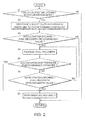
FIG. 2 is a flowchart illustrating a fuel recovery control routine executed by an engine controller according to the first embodiment of this invention; -
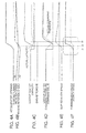
FIGS. 3A to 3F are timing charts illustrating a result of the fuel recovery control routine executed by the engine controller according to the first embodiment of this invention in a condition of a minute accelerator opening equal to or smaller than a fuel recovery determination value; -
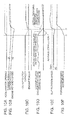
FIGS. 4A to 4F are timing charts illustrating a result of the fuel recovery control routine executed by the engine controller according to the first embodiment of this invention in a condition of an accelerator opening exceeding the fuel recovery determination value; -
FIG. 5 is a flowchart illustrating a fuel recovery control routine executed by the engine controller according to a second embodiment of this invention; -
FIGS. 6A to 6F are timing charts illustrating a result of the fuel recovery control routine executed by the engine controller according to the second embodiment of this invention in the condition of the minute accelerator opening; -
FIG. 7 is a flowchart illustrating a fuel recovery control routine executed by an engine controller according to a third embodiment of this invention; -
FIGS. 8A to 8F are timing charts illustrating a result of fuel recovery control routine executed by the engine controller according to the third embodiment of this invention in the condition of the minute accelerator opening; -
FIG. 9 is a flowchart illustrating a fuel recovery control routine executed by an engine controller according to a fourth embodiment of this invention; -
FIGS. 10A to 10F are timing charts illustrating a result of the fuel recovery control routine executed by the engine controller according to the fourth embodiment of this invention in the condition of the minute accelerator opening; -
FIGS. 11A to 11G are timing charts illustrating a result of fuel recovery in the condition of the minute accelerator opening when fuel recovery control according to this invention is not applied; and -
FIGS. 12A to 12F are timing charts illustrating a result of fuel recovery in the condition of the accelerator opening exceeding the minute accelerator opening when fuel recovery control according to this invention is not applied. - Referring to
FIG. 1 of the drawings, a vehicle driving device comprises aninternal combustion engine 1 and atransmission unit 2 that performs gear shifting for the rotation output power from theinternal combustion engine 1 and outputs it to apropeller shaft 3. - The
internal combustion engine 1 comprises anintake throttle 1A and afuel injector 1B. - The
transmission unit 2 comprises atorque converter 2B, anautomatic transmission 2A that performs gear shifting for the rotation power output from thetorque converter 2B, and ahydraulic lockup clutch 2C. - The
torque converter 2B has a structure known in the art, including a pump impeller linked to a rotation shaft of theinternal combustion engine 1 and a turbine runner coupled to an input shaft of theautomatic transmission 2A, in which a torque is transferred using a hydraulic fluid interposed between the pump impeller and the turbine runner. Theautomatic transmission 2A is a planetary gear set known in the art, including a high clutch and a low brake. - The
lockup clutch 2C, when engaged, directly connects the pump impeller and the turbine runner. When disengaged, thelockup clutch 2C frees up engagement between the pump impeller and the turbine runner. - The engaging and disengaging operations in the
lockup clutch 2C and each of the high clutch and the low brake of theautomatic transmission 2A are performed by the automatic transmission controller (ATCU) 5 using a pump pressure of a hydraulic pump provided as an accessory of theinternal combustion engine 1. - The engine controller (ECU) 4 controls an opening rate of the
intake throttle 1A for adjusting an intake air amount of theinternal combustion engine 1 and fuel injection of thefuel injector 1B of theinternal combustion engine 1. - Each of the
ECU 4 and the ATCU 5 is constituted by a microcomputer comprising a central processing unit (CPU), a read-only memory (ROM), a random access memory (RAM), and an input/output interface (I/O interface). One of the ECU 4 and the ATCU 5 or both of them may be constituted by a plurality of microcomputers. Alternatively, the ECU 4 and the ATCU 5 may be constituted by a single microcomputer. - The ECU 4 receives, via a signal circuit, each detection data from an accelerator
pedal depression sensor 6 that detects a depression amount the accelerator pedal or an accelerator opening of a vehicle, avehicle speed sensor 7 that detects a vehicle travel speed, and an enginerotation speed sensor 8 that detects a rotation speed of theinternal combustion engine 1. - The ATCU 5 receives detection data from a
shift position sensor 9 that detects a selected position of a selector of a vehicle via a signal circuit. - Referring next to
FIG. 2 , a fuel recovery control routine executed by theECU 4 as the accelerator pedal is depressed during a coast running will be described. The ECU 4 repeatedly executes this routine while a vehicle travels. That is, after a routine is terminated, the subsequent routine starts immediately. - In a step S1, the
ECU 4 determines whether or not the accelerator opening has increased from zero based on the input data from the acceleratorpedal depression sensor 6. Specifically, the determination is affirmative if the accelerator opening on the occasion of the previous routing execution is zero, and the accelerator opening on the occasion of the current routine execution is not zero. This means that a driver has depressed the accelerator pedal during a coast running of a vehicle. - Otherwise, that is, if the accelerator opening on the occasion of the previous routine execution is not zero, or if the accelerator opening on the occasion of the current routine execution is zero, the determination is negative. It should be noted that, if the accelerator opening is zero while a vehicle travels, it means that a vehicle travels by virtue of an inertial force, or in other words the vehicle is coast running. Herein, a state where the accelerator opening is zero corresponds to a state where the accelerator pedal is not depressed, or in other words to a throttle opening with which the engine runs idle.
- If the determination in the step S1 is negative, the
ECU 4 does not perform the subsequent processing and terminates the routine. - If the determination in the step S1 is affirmative, it means that a driver has depressed the accelerator pedal during the coast running of the vehicle. In this case, the
ECU 4 outputs a signal for decreasing a hydraulic pressure of thelockup clutch 2C to a predetermined pressure via the ATCU 5 in a step S2. The predetermined pressure is set to a hydraulic pressure at which a lockup clutch capacity of thelockup clutch 2C is slightly lower than an output torque of theinternal combustion engine 1 after the fuel recovery is obtained. - In a subsequent step S3, the
ECU 4 determines whether or not the accelerator opening is equal to or smaller than a fuel recovery determination value. Specifically, it is determined whether or not the accelerator opening corresponds to a minute accelerator opening at which a gear shifting operation of theautomatic transmission 2A is not generated. The fuel recovery determination value is set to, for example, 0.5/8 providing that a maximum accelerator opening is at 8/8. - If the determination in the step S3 is negative, the
ECU 4 performs fuel recovery in a step S7, thereby causing a fuel injection amount to increase in response to a request of increasing the output power of theinternal combustion engine 1 represented by the accelerator opening. The determination in the step S3 becomes negative when, for example, the accelerator pedal is depressed notably such as in a kick-down operation.. - If the determination in the step S3 is affirmative, the
ECU 4 prohibits fuel recovery in a step S4. After the processing of the step S4, theECU 4 performs a determination of a step S5. - In the step S5, the
ECU 4 determines whether or not the engaging pressure of thelockup clutch 2C has decreased to the predetermined pressure designated in the step S2. This determination may be performed using various methods. - As a direct method, the engaging pressure of the lockup clutch 2C may be actually measured using the
pressure sensor 10, and the measured value may be compared to a predetermined pressure. According to this method, it is possible to reliably assess the engaging pressure of the lockup clutch 2C. - Alternatively, it may be determined whether or not a predetermined time has elapsed since the start of the process of the step S2. The predetermined time may be defined based on a measurement result obtained in advance by measuring a time elapsing until the engaging pressure of the lockup clutch 2C actually decreases to a predetermined pressure after a signal for decreasing a pressure to a predetermined pressure is output to the lockup clutch 2C. If this determination method is employed, it is possible to omit the
pressure sensor 10 used to detect the engaging pressure of the lockup clutch 2C. - Alternatively, the rotation speed of the pump impeller of the
torque converter 2B may be used. Specifically, the aforementioned determination may be performed by detecting the rotation speed Ne of theinternal combustion engine 1 detected by the enginerotation speed sensor 8 and the rotation speed Nt of the turbine runner of thetorque converter 2B and determining whether or not an absolute value of a slip rotation speed, which is a difference between the rotation speeds Ne and the Nt, exceeds a predetermined rotation speed. The rotation speed Nt of the turbine runner is obtained from a vehicle travel speed detected by thevehicle speed sensor 7 and a selector position detected by theshift position sensor 9. The predetermined rotation speed may be set based on a result of experiment or simulation performed in advance for the slip rotation speed at the predetermined pressure designated in the step S2. Similarly, when this determination method is employed, it is possible to omit thepressure sensor 10. - If it is determined that the hydraulic pressure of the
lockup clutch 2C has decreased to the predetermined pressure in the step S5, it means that thelockup clutch 2C disengages so that a change of the engine rotation speed caused by fuel recovery can be absorbed by thetorque converter 2B. In this case, theECU 4 performs fuel recovery in the step S7. After the fuel recovery, theECU 4 terminates the routine. - Meanwhile, if it is determined that the hydraulic pressure of the
lockup clutch 2C has not decreased to the predetermined pressure in the step S5, theECU 4 determines if a recovery delay condition is satisfied in a step S6. - Specifically, this determination is made by determining whether or not the accelerator opening is greater than the fuel recovery determination value 0.5/8. If the accelerator opening is greater than the fuel recovery determination value 0.5/8, it means that the accelerator opening has exceeded a target accelerator opening region for the recovery delay control. In this case, the
ECU 4 performs fuel recovery in the step S7. After the fuel recovery, theECU 4 terminates the routine. Even when the accelerator opening is equal to or lower than the fuel recovery determination value 0.5/8 at the routine start timing, if the accelerator opening exceeds the fuel recovery determination value 0.5/8 during the routine execution, the fuel recovery is immediately executed since the determination in the step S6 changes to be affirmative from negative. As a result, a high response is ensured with respect to the accelerator pedal depression so as to accelerate a vehicle. - In the step S6, when the accelerator opening does not exceed the fuel recovery determination value 0.5/8, the
ECU 4 determines that the recovery delay condition is satisfied. In this case, theECU 4 repeats the processing subsequent to the step S4 to suspend the furl recovery. - As described above, in this routine, for minute accelerator pedal depression during a coast running, a processing for decreasing the engaging pressure of the lockup clutch 2C immediately starts, and recovery from the fuel cut-off state is delayed until the engaging pressure of the lockup clutch decreases to a level at which a torque shock can be absorbed. Therefore, it is possible to alleviate an influence on a travel speed caused by minute unintentional depression of the accelerator pedal during a coast running and prevent the driver or the passenger from feeling discomfort.
- Referring to
FIGS. 3A-3F , a result of the fuel recovery control routine executed by theECU 4 in a condition of a minute accelerator opening equal to or smaller than a fuel recovery determination value will be described. - During a coast running of the vehicle, a fuel cut-off operation is executed and the accelerator opening keeps zero as illustrated in
FIG. 3A . Meanwhile, theATCU 5 maintains the engaging pressure of thelockup clutch 2C as illustrated inFIG. 3D , and the lockup clutch capacity is maintained in the value of the engagement state as illustrated inFIG. 3C . Here, the lockup clutch capacity means a maximum transmittable torque in the current engagement state of the lockup clutch 2C. - An engine brake is applied in this state to the vehicle travelling by virtue of an inertial force, so that the engine rotation speed Ne, that is, a rotation speed of the pump impeller of the
torque converter 2B, is slightly lower than the rotation speed Nt of the turbine runner as illustrated inFIG. 3B . Therefore, the slip rotation speed being a difference between the two rotation speeds, has a negative value as illustrated inFIG. 3E . - In the fuel recovery control routine executed in this state, the determination in the step S1 is negative. Therefore, the fuel recovery is not executed, and the fuel cut-off state is maintained.
- At a time t1, as the driver slightly depresses the accelerator pedal, the determination of the step S1 changes to be affirmative in the subsequent execution of the fuel recovery control routine. As a result, in the step S2, the
ECU 4 outputs a command signal for decreasing the engaging pressure to the lockup clutch 2C via theATCU 5 as illustrated inFIG. 3D . Due to a response delay in a hydraulic pressure used to generate the engaging pressure, even when an engaging pressure command value decreases in a stepwise fashion, both an actual engaging pressure indicated by the dotted line inFIG. 3D and an actual lockup capacity indicated by the dotted line inFIG. 3C decrease gradually. - When the accelerator pedal depression amount is minute, the determination of the step S3 in the fuel recovery control routine changes to be affirmative, and fuel recovery is prohibited in the step S4. The fuel recovery is continuously prohibited in the step S4 until the engaging pressure of the
lockup clutch 2C becomes equal to or lower than the predetermined pressure at a time t2. - As the engaging pressure of the lockup clutch 2C decreases to the predetermined pressure or lower at the time t2, the determination of the step S5 changes to be affirmative. As a result, the fuel recovery operation in the step S7 is executed, and fuel supply to the
internal combustion engine 1 is resumed. - As a result, the engine torque at the time t2 increases as illustrated in
FIG. 3C , and the engine rotation speed Ne also increases as illustrated inFIG. 3B . At this moment, as illustrated inFIGS. 3C and 3D , thelockup clutch 2C has disengaged. For this reason, as illustrated inFIG. 3B , the engine rotation speed Ne finally exceeds the rotation speed Nt of the turbine runner, which is an input rotation speed of theautomatic transmission 2A. The slip rotation speed corresponding to the speed difference there-between temporarily increases as illustrated inFIG. 3E . However, since the speed difference is absorbed in thetorque converter 2B, the slip rotation speed thus increased converges to zero. - An acceleration of the vehicle in a forward/backward direction is maintained constant during a coast running as illustrated in
FIG. 3F , and a deceleration starts to decrease at the time t1 in which the command for decreasing the engaging pressure command value of thelockup clutch 2C is output. In addition, the deceleration smoothly decreases toward zero until the vehicle speed becomes constant after the time t2. - If the fuel recovery control routine is executed as described above, an unintentional change of the vehicle travel speed is suppressed when the driver slightly depresses the accelerator pedal during a coast running of the vehicle. Therefore, it is possible to prevent the driver or the passenger from feeling discomfort caused by minute unintentional accelerator pedal depression.
- Referring to
FIGS. 11A to 11G , description will now be made for a vehicle behavior when the accelerator pedal is slightly depressed not exceeding the fuel recovery determination value during the coast running of the vehicle, and the fuel recovery control routine according to this invention is not executed. - In this case, a vehicle coasts, that is, the internal combustion engine has a negative driving force, and the lockup clutch is engaged until the time t1 as illustrated in
FIG. 11C . This state will be referred to as a coast lockup state mCSTSLT. As a driver slightly depresses the accelerator pedal at the time t1, theECU 4 outputs a command value for decreasing the engaging pressure to thelockup clutch 2C as illustrated inFIG. 11F via theATCU 5. At the same time, theECU 4 executes fuel recovery. As a result, the engine torque starts to increase from timing t1 as illustrated inFIG. 11E . - After the time t1, a vehicle drives normally in pattern, that is, the internal combustion engine has a positive driving force, and the lockup clutch slips. This state will be referred to as a drive slip state mSLP. However, in practice, due to a response delay in the hydraulic pressure of the
lockup clutch 2C, the engaging pressure decreases gradually as indicated by the dotted line inFIG. 11E . Therefore, the lockup clutch capacity ofFIG. 11D also decreases gradually. - In this manner, as the engine torque increases in a state that the
lockup clutch 2C maintains a high clutch capacity, in other words, in a substantial engagement state, the increasing engine torque is directly applied to thepropeller shaft 3 via the lockup clutch 2C. As a result, as indicated by the area enclosed by the dot-dashed line inFIG. 11G , an acceleration of a vehicle in a forward/backward direction abruptly changes to generate a shock in a chassis or make a driver or a passenger feel discomfort. - Referring next to
FIGS. 4A - 4F , description will be made for a result of the fuel recovery control routine executed by theECU 4 when the accelerator pedal is depressed beyond the fuel recovery determination value 0.5/8. - In this case, the operation similar to that of
FIGS. 3A to 3F is performed until the time t1. As the accelerator pedal is depressed at the time t1, the determination of the step S1 changes to be affirmative in the subsequent execution of the fuel recovery control routine, and theECU 4 outputs a command value for decreasing the engaging pressure to the lockup clutch 2C via theATCU 5 in the step S2 as illustrated inFIG. 4D . Due to a response delay in the hydraulic pressure, as the engaging pressure command value decreases, both the actual engaging pressure indicated by the dotted line inFIG. 4D and the lockup clutch capacity indicated by the dotted line ofFIG. 4C decrease gradually. - Since the determination in the step S6 is negative until the accelerator opening exceeds 0.5/8, the fuel recovery is repeatedly prohibited in the step S4.
- As the accelerator opening exceeds 0.5/8 at the time t3, the determination of the step S6 changes to be affirmative, and the fuel recovery is executed in the step S7. Since the determination of the step S3 becomes negative in the subsequent execution of the routine, the fuel recovery is repeatedly executed.
- As a result, as illustrated in
FIG. 4C , the engine torque increases at the time t3. Thereafter, the engine torque is generated depending on the depression level of the accelerator pedal. - When the accelerator opening exceeds the fuel recovery determination value 0.5/8 at the time t3, the fuel recovery starts immediately. As a result, as indicated by the area enclosed by the dotted line of
FIG. 4F , an acceleration of a vehicle in a forward/backward direction changes to a positive value after the time t3. - In this fuel recovery control routine, as the accelerator opening exceeds the fuel recovery determination value, the fuel recovery is executed regardless of the lockup clutch capacity. The lockup clutch 2C is re-engaged when the engine torque is recovered to a certain level through the fuel recovery.
- That is, when a driver intends to accelerate the vehicle and depresses the accelerator pedal, the fuel recovery is executed immediately. Therefore, it is possible to prevent acceleration caused by depressing the accelerator pedal from being delayed. Accordingly, it is possible to accelerate the vehicle promptly in response to depression of the accelerator pedal.
- Therefore, according to this embodiment, as the accelerator pedal is depressed during a coast running, it is possible to prevent a shock caused by a timing deviation between disengagement of the
lockup clutch 2C and fuel recovery without degrading acceleration performance of a vehicle. - Referring to
FIGS. 12A to 12F , description will now be made for a vehicle behavior when the accelerator pedal is depressed over the fuel recovery determination value during a coast running of a vehicle, and the fuel recovery control routine according to this invention is not executed. - In this case, as a driver depresses the accelerator pedal at the time t1, the
ECU 4 outputs a command value for decreasing the engaging pressure to the lockup clutch 2C via theATCU 5 as illustrated inFIG. 12E . At the same time, theECU 4 executes the fuel recovery. As a result, the engine torque starts to increase from the time t1 as illustrated inFIG. 12F . - Meanwhile, even when a command value for decreasing the engaging pressure is output to the
lockup clutch 2C, due to a response delay of the hydraulic pressure, both the actual engaging pressure indicated by the dotted line ofFIG. 12D and the lockup clutch capacity indicated by the dotted line ofFIG. 12C decrease with a delay as the engaging pressure command value decreases. - As a result, the engine torque increases while the
lockup clutch 2C is not substantially disengaged. That is, since the increasing engine torque is directly transmitted to thepropeller shaft 3, a fluctuation is generated in the acceleration of a vehicle in a forward/backward direction as indicated by the area enclosed by the dot-dashed line ofFIG. 12F . This generates a shock in a chassis and makes the driver or a passenger feel discomfort. - Referring to
FIG. 5 , the fuel recovery control routine executed by theECU 4 according to the second embodiment of this invention will be described. This routine is executed instead of the fuel recovery control routine ofFIG. 2 of the first embodiment. Therefore, a routine execution condition is identical to that of the first embodiment. - This fuel recovery control routine is different from that of
FIG. 2 in that the step S4 is substituted with a step S4A. The steps S1 to S3 and the steps S5 to S7 are identical to those ofFIG. 2 . - When the determination in the step S3 is affirmative, the
ECU 4 prohibits the fuel recovery in a half of cylinders of theinternal combustion engine 1 in the step S4A. That is, if theinternal combustion engine 1 has eight cylinders, the fuel recovery is prohibited in four cylinders, and the fuel recovery is performed in the remaining four cylinders. - The number of cylinders where the fuel recovery is prohibited may not be necessarily set to a half of the cylinders. By prohibiting the fuel recovery in a part of the cylinders, the output power of the
internal combustion engine 1 is suppressed to a low value, compared to a case where the fuel recovery is performed in overall cylinders. - It is conceivable that the fuel recovery is once prohibited in overall cylinders as the accelerator pedal is depressed, and then, the prohibition of the fuel recovery is released sequentially one by one as time elapses. In this case, it is possible to smoothly increase the output torque of the
internal combustion engine 1. - Referring to
FIGS. 6A to 6F , a result of executing the fuel recovery control routine according to the second embodiment will be described. In this case, it is assumed that the fuel recovery is prohibited in a half of the cylinders in the step S4A. - In this embodiment also, the conditions until the time t1 are identical to those of
FIGS. 3A to 3F . As a driver slightly depresses the accelerator pedal at the time t1, the determination in the step S1 changes to be affirmative. As a result, in the step S2, theECU 4 outputs a command value for decreasing the engaging pressure to the lockup clutch 2C via theATCU 5 as illustrated inFIG. 6D . Due to a response delay of the hydraulic pressure, both the actual engaging pressure indicated by the dotted line inFIG. 6D and the lockup capacity indicated by the dotted line inFIG. 6C decrease gradually in contrast to a sudden decrease in the engaging pressure command value. - Meanwhile, since the determination in the step S3 becomes affirmative, the fuel recovery is prohibited in a half of the cylinders in the step S4A. As a result, the engine torque slightly increases, compared to that of the coast running, as illustrated in
FIG. 6C . In this state, while thelockup clutch 2C maintains a high clutch capacity, an increase in the engine torque is small. Therefore, as illustrated inFIG. 6F , an acceleration of a vehicle in a forward/backward direction stably increases without fluctuation. - If the fuel recovery is prohibited for overall cylinders, the engine rotation speed Ne may decrease as the
lockup clutch 2C disengages as indicated by the dotted line ofFIG. 6B . However, since the fuel recovery is prohibited in a part of the cylinders, but is allowed in the remaining cylinders, the engine torque slightly increases as a whole. Therefore, a decrease in the engine rotation speed Ne due to a disengagement of thelockup clutch 2C does not occur. - In this manner, as the engaging pressure of the lockup clutch 2C decreases to the predetermined pressure at the time t2, the prohibition of the fuel recovery in the half of the cylinders is released in a step S7A. As a result, the engine torque increases again, and thereafter the engine torque changes depending on the accelerator depression level. At this moment, since the engaging pressure of the
lockup clutch 2C has decreased to the predetermined pressure, thelockup clutch 2C is substantially disengaged. - Therefore, an increase in the engine torque does not abruptly change the torque transmitted to the
propeller shaft 3, but temporarily increases the slip rotation speed as illustrated inFIG. 6E . As a result, an acceleration of a vehicle in a forward/backward direction stably increases without fluctuation as illustrated inFIG. 6F . - Referring to
FIG. 7 , a fuel recovery control routine executed by theECU 4 according to the third embodiment of this invention will be described. This routine is executed instead of the fuel recovery control routine ofFIG. 2 of the first embodiment. Therefore, the routine execution condition is identical to that of the first embodiment. - This fuel recovery control routine is different from that of
FIG. 2 in that the step S4 is substituted with the step S4B, and the step S7 is substituted with the step S7B. Other steps are identical to those of the routine ofFIG. 2 . - In the step S4B, the
ECU 4 prohibits fuel recovery in overall cylinders and prohibits the opening rate of theintake throttle 1A, that is, the throttle opening from increasing. Since theintake throttle 1A is synchronized with the accelerator pedal, the throttle opening increases as the accelerator pedal is depressed. In the step S4B, both the fuel recovery and the increase in the throttle opening are prohibited. - In the step S7B, the
ECU 4 releases the prohibition of the fuel recovery and the increase in the throttle opening. As a result, fuel supply to theinternal combustion engine 1 is resumed, and the opening rate of theintake throttle 1A increases depending on the depression of the accelerator pedal. - Referring next to
FIGS. 8A to 8F , a result of executing the fuel recovery control routine according to the third embodiment will be described. - With this fuel recovery control routine, both the fuel recovery and the increase in the opening rate of the
intake throttle 1A are prohibited in overall cylinders during a recovery delay period until the time t2 after a driver slightly depresses the accelerator pedal at the time t1. As the recovery delay period is terminated at the time t2, the throttle opening increases as indicated by the dot-dashed line inFIG. 8A . If the intake air amount of theinternal combustion engine 1 is suppressed to a low level during the recovery delay period, the output torque caused by the fuel recovery smoothly increases, as indicated by the dot-dashed line inFIG. 8C , even when the fuel recovery is immediately performed at the time t2, due to a response delay of the intake air amount against an increase in the accelerator opening. On the contrary, if the throttle opening increases during the recovery delay period from the time t1 to the time t2 as indicated by the solid line inFIG. 8A , the fuel recovery is executed at the time t2, and the output torque abruptly increases as indicated by the solid line inFIG. 8C . According to this embodiment, it is possible to reduce a torque gap that may appear at the time t2 by suppressing an increase in the throttle opening during the recovery delay period. As a result, it is possible to suppress a shock caused by the torque gap. In addition, since the intake air amount in the fuel recovery is suppressed, it is possible to suppress an abrupt increase in the rotation of theinternal combustion engine 1 immediately after the fuel recovery, thereby enabling smoothly re-engagement of the lockup clutch 2C. - Referring to
FIG. 9 , a fuel recovery control routine executed by theECU 4 according to the fourth embodiment of this invention will be described. This routine is executed instead of the fuel recovery control routine of the first embodiment. The execution condition is identical to that of the first or second embodiment. - In this routine, the step S2 of the routine of
FIG. 2 of the first embodiment is substituted with a step S2A. In addition, if the determination in the step S6 is negative, the processing is executed again not from the step S4, but from the step S2A. - In the step S2A, the
ECU 4 applies an advance correction to the engaging pressure command value before it is output to the lockup clutch 2C. Specifically, by setting the engaging pressure command value to a value lower than the predetermined pressure, a decrease in the engaging pressure of thelockup clutch 2C is accelerated. In addition, theECU 4 performs feedback control of the engaging pressure by repeatedly processing the steps S2A to S6 such that the engaging pressure of the lockup clutch 2C finally converges to the predetermined pressure. As a result, the processing of the step S2A is repeatedly executed from the time t1 at which the accelerator pedal is depressed to the time t2 at which the engaging pressure of the lockup clutch 2C decreases to the predetermined pressure. - Other steps are identical to those of the fuel recovery control routine of
FIG. 2 of the first embodiment. - Referring to
FIGS. 10A to 10F , a result of executing the fuel recovery control routine ofFIG. 8 by theECU 4 according to the third embodiment under a minute accelerator depression equal to or lower than the fuel recovery determination value will be described - As a driver slightly depresses the accelerator pedal at the time t1 during a coast running of a vehicle, the
ECU 4 outputs a command value for decreasing the engaging pressure to the lockup clutch 2C via theATCU 5 in the step S2A as illustrated inFIG. 10D . By applying an advance correction to this command value, a decrease in the actual engaging pressure is expedited as indicated by the dot-dashed line ofFIG. 10D , compared to a case where the advance correction is not applied as indicated by the dotted line. As a result, the recovery delay period from the time t1 to the time t2 at which the engaging pressure of the lockup clutch 2C decreases to the predetermined pressure is shortened. - During a period from the time t1 to the time t2, a process for decreasing the output power of the
internal combustion engine 1 is repeatedly performed in the step S4A. As illustrated inFIG. 10C , the engine torque is suppressed to a low value until the engaging pressure of the lockup clutch 2C decreases to the predetermined pressure. Therefore, the acceleration of a vehicle in a forward/backward direction smoothly increases as illustrated inFIG. 10F . In addition, a shock due to an increase in the engine torque while thelockup clutch 2C is substantially engaged is not promoted. - In addition, according to this embodiment, by applying the advance correction to the engaging pressure command value of the
lockup clutch 2C, the output power decreasing period of theinternal combustion engine 1 from the time t1 to the time t2 is shortened. Therefore, it is possible to shorten a response time elapsing from the depression of the accelerator pedal to the increase in the vehicle travel speed. - As described above, according to this invention, when the accelerator pedal is slightly depressed during a coast running of a vehicle, the fuel recovery of the internal combustion engine is suppressed until the engaging pressure of the lockup clutch 2C decreases to a predetermined pressure or lower. Therefore, it is possible to prevent a driver or a passenger from feeling discomfort caused by an influence on a vehicle speed generated by increasing the output power of the
internal combustion engine 1 while thelockup clutch 2C is substantially engaged. - The contents of Tokugan 2011-133649, with a filing date of June 15, 2011 in Japan, are hereby incorporated by reference.
- Although the invention has been described above with reference to certain embodiments, the invention is not limited to the embodiments described above. Modifications and variations of the embodiments described above will occur to those skilled in the art, within the scope of the claims.
- As described above, the vehicle driving device according to this invention prevents a passenger from feeling discomfort caused by a shock generated by fuel recovery and transmitted via a lockup clutch. Accordingly, this invention brings about a favorable result in improving a riding comfort of, for example, a passenger vehicle.
- The embodiments of this invention in which an exclusive property or privilege is claimed are defined as follows:
Claims (12)
- A vehicle driving device, comprising:an internal combustion engine (1) generating an output power by combustion of fuel supplied in response to a depression of an accelerator pedal of a vehicle while performing a fuel cut during a coast running of the vehicle in which the accelerator pedal is not depressed;a torque converter (2B) that transmits the output power of the internal combustion engine (1) to a drive wheel of the vehicle via a pump impeller and a turbine runner;a lockup clutch (2C) that is engaged, when the vehicle performs the coast running, to directly connects the pump impeller with the turbine runner;an accelerator pedal depression sensor (6) that detects a depression of the accelerator pedal during the coast running; anda programmable controller (4) programmed to:operates the lockup clutch (2C) to disengage in response to the depression of the accelerator pedal during the coast running of the vehicle; andsuppress a fuel recovery of the internal combustion engine in response to the depression of the accelerator pedal during the coast running of the vehicle until an engaging pressure of the lockup clutch (2C) decreases to a predetermined pressure.
- The vehicle driving device according to Claim 1, wherein the controller (4) is further programmed to prohibit the fuel recovery of the internal combustion engine in response to the depression of the accelerator pedal until the engaging pressure of the lockup clutch (2C) decreases to the predetermined pressure.
- The vehicle driving device according to Claim 2, wherein the internal combustion engine (1) comprises a multi-cylinder engine and the controller is further programmed to prohibit the fuel recovery in only one or a few of the cylinders of the internal combustion engine in response to the depression of the accelerator pedal during the coast running of the vehicle until the engaging pressure of the lockup clutch (2C) decreases to the predetermined pressure.
- The vehicle driving device according to any one of Claims 1 to 3, wherein the controller (4) is further programmed not to suppress the fuel recovery when a depression amount of the accelerator pedal during the coast running exceeds a predetermined amount.
- The vehicle driving device according to any one of Claims 1 to 4, wherein the internal combustion engine (1) comprises an intake throttle (1A) and generates the output power according to a fuel supplied in response to an intake air amount that is regulated by the intake throttle (1A), and the controller (4) is further programmed to prohibit a throttle opening of the intake throttle (1A) from increasing as long as the fuel recovery is suppressed.
- The vehicle driving device according to any one of Claims 1 to 5, wherein the controller (4) is further programmed to operates the lockup clutch (2C) to disengage by outputting an engaging pressure decrease command signal and apply an advance correction to the engaging pressure decrease command signal in response to the depression of the accelerator pedal during the coast running of the vehicle.
- The vehicle driving device according to any one of Claims 1 to 6, wherein the controller (4) is further programmed to determine whether or not the engaging pressure of the lockup clutch has decreased to the predetermined pressure depending on an elapsed time from a start of disengaging operation of the lockup clutch (2C).
- The vehicle driving device according to any one of Claims 1 to 6, further comprising a sensor (10) that detects the engaging pressure of the lockup clutch (2C), wherein the controller (4) is further programmed to determine that the engaging pressure of the lockup clutch has decreased to the predetermined pressure when the engaging pressure of the lockup clutch (2C) detected by the sensor (10) has decreased to the predetermined pressure.
- The vehicle driving device according to any one of Claims 1 to 6, further comprising a sensor (8, 9) that detects a slip rotation speed between the pump impeller and the turbine runner, wherein the controller (4) is further programmed to determine that the engaging pressure of the lockup clutch has decreased to the predetermined pressure when the slip rotation speed has become equal to or greater than a predetermined speed.
- The vehicle driving device according to any one of Claims 1 to 9, wherein the controller (4) is further programmed to stop suppressing the fuel recovery when the depression amount of the accelerator pedal becomes equal to or greater than a predetermined amount even if the engaging pressure of the lockup clutch has not decreased to the predetermined pressure.
- A vehicle driving device for a vehicle, comprising:an internal combustion engine (1) generating an output power by combustion of fuel supplied in response to a depression of an accelerator pedal of a vehicle while performing a fuel cut during a coast running of the vehicle in which the accelerator pedal is not depressed;a torque converter (2B) that transmits the output power of the internal combustion engine (1) to a drive wheel of the vehicle via a pump impeller and a turbine runner;a lockup clutch (2C) that is engaged, when the vehicle performs the coast running, to directly connects the pump impeller with the turbine runner;an accelerator pedal depression means (6) that detects a depression of the accelerator during the coast running;a lockup clutch disengaging operating means (4, S2, S2A) for operating the lockup clutch (2C) to disengage in response to the depression of the accelerator pedal during the coast running of the vehicle; anda recovery suppressing means (4, S4, S4A) for suppressing a fuel recovery of the internal combustion engine in response to the depression of the accelerator pedal during the coast running of the vehicle until an engaging pressure of the lockup clutch (2C) decreases to a predetermined pressure.
- A vehicle driving method for a vehicle, the vehicle comprising an internal combustion engine (1) generating an output power by combustion of fuel supplied in response to a depression of an accelerator pedal of a vehicle while performing a fuel cut during a coast running of the vehicle in which the accelerator pedal is not depressed, a torque converter (2B) that transmits the output power of the internal combustion engine (1) to a drive wheel of the vehicle via a pump impeller and a turbine runner, and a lockup clutch (2C) that is engaged, when the vehicle performs the coast running, to directly connects the pump impeller with the turbine runner, the method comprising:detecting a depression of the accelerator during the coast running;operating the lockup clutch (2C) to disengage in response to the depression of the accelerator pedal during the coast running of the vehicle; andsuppressing a fuel recovery of the internal combustion engine in response to the depression of the accelerator pedal during the coast running of the vehicle until an engaging pressure of the lockup clutch (2C) decreases to a predetermined pressure.
Applications Claiming Priority (2)
| Application Number | Priority Date | Filing Date | Title |
|---|---|---|---|
| JP2011133649 | 2011-06-15 | ||
| PCT/JP2012/055692 WO2012172840A1 (en) | 2011-06-15 | 2012-03-06 | Vehicle drive device and method |
Publications (3)
| Publication Number | Publication Date |
|---|---|
| EP2722512A1 true EP2722512A1 (en) | 2014-04-23 |
| EP2722512A4 EP2722512A4 (en) | 2016-07-20 |
| EP2722512B1 EP2722512B1 (en) | 2017-12-06 |
Family
ID=47356839
Family Applications (1)
| Application Number | Title | Priority Date | Filing Date |
|---|---|---|---|
| EP12800924.8A Active EP2722512B1 (en) | 2011-06-15 | 2012-03-06 | Vehicle driving device and vehicle driving method |
Country Status (10)
| Country | Link |
|---|---|
| US (1) | US9050964B2 (en) |
| EP (1) | EP2722512B1 (en) |
| JP (1) | JP5764657B2 (en) |
| KR (1) | KR101594234B1 (en) |
| CN (1) | CN103502611B (en) |
| BR (1) | BR112013030327B1 (en) |
| MX (1) | MX2013012856A (en) |
| MY (1) | MY157392A (en) |
| RU (1) | RU2563307C2 (en) |
| WO (1) | WO2012172840A1 (en) |
Families Citing this family (15)
| Publication number | Priority date | Publication date | Assignee | Title |
|---|---|---|---|---|
| JP5936572B2 (en) * | 2013-03-25 | 2016-06-22 | ジヤトコ株式会社 | Vehicle control device |
| GB2525138B (en) * | 2013-09-11 | 2016-06-08 | Jaguar Land Rover Ltd | Vehicle controller and method |
| WO2016035169A1 (en) | 2014-09-03 | 2016-03-10 | 日産自動車株式会社 | Lock-up clutch control device for vehicle |
| JP6412635B2 (en) * | 2015-03-30 | 2018-10-24 | ジヤトコ株式会社 | Control device and control method for automatic transmission |
| EP3279521B1 (en) | 2015-03-30 | 2020-11-18 | Nissan Motor Co., Ltd. | Automatic transmission control device and control method |
| KR101734262B1 (en) * | 2015-08-12 | 2017-05-11 | 현대자동차 주식회사 | Apparatus for controlling autotransmission and methof thereof |
| JP6568754B2 (en) * | 2015-09-11 | 2019-08-28 | ジヤトコ株式会社 | VEHICLE DRIVE DEVICE AND CONTROL METHOD FOR VEHICLE DRIVE DEVICE |
| JP6372621B2 (en) * | 2015-10-23 | 2018-08-15 | 日産自動車株式会社 | Vehicle lockup control method and control device |
| CN106246762B (en) * | 2016-10-08 | 2019-01-29 | 盛瑞传动股份有限公司 | A kind of converter lockout clutch control method under urgency accelerator releasing operating condition |
| US10131357B2 (en) * | 2017-02-13 | 2018-11-20 | Ford Global Technologies, Llc | Vehicle control during tip-in |
| CN110242743B (en) * | 2018-03-09 | 2021-01-22 | 上海汽车集团股份有限公司 | Control method and control system of hydraulic torque converter |
| JP7139972B2 (en) * | 2019-01-24 | 2022-09-21 | トヨタ自動車株式会社 | In-vehicle control device |
| CN110195748B (en) * | 2019-05-31 | 2021-01-01 | 广东轻工职业技术学院 | A variable pressure automobile hydraulic clutch assist system and method |
| JP7084443B2 (en) * | 2020-03-19 | 2022-06-14 | 本田技研工業株式会社 | Vehicle control unit and vehicle |
| JP7435518B2 (en) * | 2021-03-26 | 2024-02-21 | トヨタ自動車株式会社 | Vehicle control device |
Family Cites Families (21)
| Publication number | Priority date | Publication date | Assignee | Title |
|---|---|---|---|---|
| JPS62106174A (en) * | 1985-10-30 | 1987-05-16 | Fuji Heavy Ind Ltd | Control device for automatic speed change gear with lock up device |
| JPH0811510B2 (en) * | 1986-04-15 | 1996-02-07 | 本田技研工業株式会社 | Fuel supply in vehicle engine and method for controlling clutch for fluid torque converter |
| JP3303541B2 (en) * | 1994-08-02 | 2002-07-22 | 日産自動車株式会社 | Lockup control device for fluid transmission |
| JP3368686B2 (en) * | 1994-09-29 | 2003-01-20 | 株式会社デンソー | Auxiliary device for internal combustion engine for vehicles |
| JP3458500B2 (en) | 1994-12-27 | 2003-10-20 | 日産自動車株式会社 | Transmission control device for continuously variable transmission |
| JPH0968084A (en) | 1995-08-30 | 1997-03-11 | Mitsubishi Electric Corp | Idle speed control device for internal combustion engine |
| JP3791288B2 (en) * | 1999-06-18 | 2006-06-28 | トヨタ自動車株式会社 | Control device for in-vehicle internal combustion engine |
| US6345223B1 (en) * | 1999-09-30 | 2002-02-05 | Nissan Motor Co., Ltd. | Lock-up control device for vehicle |
| JP4310888B2 (en) * | 2000-05-23 | 2009-08-12 | トヨタ自動車株式会社 | Vehicle clutch control device |
| JP4119613B2 (en) * | 2001-01-11 | 2008-07-16 | ジヤトコ株式会社 | Automatic transmission lockup control device |
| JP2003041959A (en) * | 2001-08-01 | 2003-02-13 | Honda Motor Co Ltd | Hybrid vehicle control device |
| JP3664118B2 (en) * | 2001-08-07 | 2005-06-22 | トヨタ自動車株式会社 | Control device for vehicle equipped with internal combustion engine |
| JP4191968B2 (en) * | 2002-08-27 | 2008-12-03 | トヨタ自動車株式会社 | Vehicle drive control device |
| JP2005172078A (en) * | 2003-12-10 | 2005-06-30 | Nissan Motor Co Ltd | Torque converter lockup control device |
| JP2006015819A (en) | 2004-06-30 | 2006-01-19 | Nissan Motor Co Ltd | Fuel recovery shock mitigation device for vehicle powertrain |
| JP4329084B2 (en) | 2005-11-04 | 2009-09-09 | 株式会社デンソー | Control device for accumulator fuel system |
| JP2007255629A (en) * | 2006-03-24 | 2007-10-04 | Jatco Ltd | Vehicle control device |
| JP4240049B2 (en) * | 2006-04-11 | 2009-03-18 | トヨタ自動車株式会社 | Powertrain control device |
| JP2009150513A (en) * | 2007-12-21 | 2009-07-09 | Toyota Motor Corp | Power transmission control device |
| JP2009250071A (en) * | 2008-04-02 | 2009-10-29 | Denso Corp | Control device for internal combustion engine |
| JP5011246B2 (en) * | 2008-09-22 | 2012-08-29 | 川崎重工業株式会社 | Vehicle and fuel cut control method |
-
2012
- 2012-03-06 JP JP2013520449A patent/JP5764657B2/en active Active
- 2012-03-06 RU RU2014101055/11A patent/RU2563307C2/en active
- 2012-03-06 MY MYPI2013004466A patent/MY157392A/en unknown
- 2012-03-06 KR KR1020137032864A patent/KR101594234B1/en not_active Expired - Fee Related
- 2012-03-06 MX MX2013012856A patent/MX2013012856A/en active IP Right Grant
- 2012-03-06 CN CN201280021465.4A patent/CN103502611B/en active Active
- 2012-03-06 US US14/126,232 patent/US9050964B2/en active Active
- 2012-03-06 EP EP12800924.8A patent/EP2722512B1/en active Active
- 2012-03-06 WO PCT/JP2012/055692 patent/WO2012172840A1/en not_active Ceased
- 2012-03-06 BR BR112013030327-1A patent/BR112013030327B1/en active IP Right Grant
Also Published As
| Publication number | Publication date |
|---|---|
| RU2014101055A (en) | 2015-07-27 |
| EP2722512A4 (en) | 2016-07-20 |
| US9050964B2 (en) | 2015-06-09 |
| MX2013012856A (en) | 2013-12-02 |
| JP5764657B2 (en) | 2015-08-19 |
| CN103502611B (en) | 2017-02-15 |
| BR112013030327A2 (en) | 2017-11-07 |
| KR101594234B1 (en) | 2016-02-15 |
| US20140129103A1 (en) | 2014-05-08 |
| MY157392A (en) | 2016-06-15 |
| BR112013030327B1 (en) | 2021-03-16 |
| CN103502611A (en) | 2014-01-08 |
| KR20140008456A (en) | 2014-01-21 |
| RU2563307C2 (en) | 2015-09-20 |
| JPWO2012172840A1 (en) | 2015-02-23 |
| EP2722512B1 (en) | 2017-12-06 |
| WO2012172840A1 (en) | 2012-12-20 |
Similar Documents
| Publication | Publication Date | Title |
|---|---|---|
| EP2722512B1 (en) | Vehicle driving device and vehicle driving method | |
| JP4321253B2 (en) | Torque converter lockup control device | |
| JP5839115B2 (en) | Vehicle starting clutch control device | |
| JP5720796B2 (en) | Vehicle control device | |
| WO2011007420A1 (en) | Control device for vehicle | |
| US10024243B2 (en) | Vehicle driving device and vehicle driving method | |
| JP6011352B2 (en) | Vehicle coasting control device | |
| JP2010038300A (en) | Control device and control method of vehicle | |
| JP5880355B2 (en) | Vehicle starting clutch control device | |
| US20150353086A1 (en) | Control device for vehicle and control method for vehicle | |
| JP5825437B2 (en) | Control device for internal combustion engine | |
| JP2009150513A (en) | Power transmission control device | |
| JP2017044136A (en) | Control device of internal combustion engine | |
| JP6583130B2 (en) | Vehicle control device | |
| JP5355164B2 (en) | Control device for automatic transmission | |
| JP2017198311A (en) | Control device of vehicle | |
| JP2016141164A (en) | Vehicle control device | |
| JP6187402B2 (en) | Control device for vehicle drive unit | |
| CN117460882A (en) | Vehicle control method and vehicle control device | |
| JP2017088052A (en) | Vehicular control apparatus | |
| JP5533710B2 (en) | Control device for vehicle lock-up clutch | |
| JP6481536B2 (en) | ENGINE CONTROL METHOD AND ENGINE CONTROL DEVICE | |
| JP2009286272A (en) | Control device and control method for vehicle | |
| WO2010097919A1 (en) | Automatic transmission control device | |
| JP2017137986A (en) | Vehicle control device |
Legal Events
| Date | Code | Title | Description |
|---|---|---|---|
| PUAI | Public reference made under article 153(3) epc to a published international application that has entered the european phase |
Free format text: ORIGINAL CODE: 0009012 |
|
| 17P | Request for examination filed |
Effective date: 20140108 |
|
| AK | Designated contracting states |
Kind code of ref document: A1 Designated state(s): AL AT BE BG CH CY CZ DE DK EE ES FI FR GB GR HR HU IE IS IT LI LT LU LV MC MK MT NL NO PL PT RO RS SE SI SK SM TR |
|
| DAX | Request for extension of the european patent (deleted) | ||
| RA4 | Supplementary search report drawn up and despatched (corrected) |
Effective date: 20160616 |
|
| RIC1 | Information provided on ipc code assigned before grant |
Ipc: B60W 10/04 20060101ALI20160610BHEP Ipc: B60W 10/11 20120101ALI20160610BHEP Ipc: F02D 9/02 20060101ALI20160610BHEP Ipc: B60W 10/06 20060101ALI20160610BHEP Ipc: F02D 41/10 20060101ALI20160610BHEP Ipc: F02D 29/00 20060101AFI20160610BHEP Ipc: F02D 45/00 20060101ALI20160610BHEP Ipc: F16H 61/14 20060101ALI20160610BHEP |
|
| GRAP | Despatch of communication of intention to grant a patent |
Free format text: ORIGINAL CODE: EPIDOSNIGR1 |
|
| INTG | Intention to grant announced |
Effective date: 20170626 |
|
| GRAS | Grant fee paid |
Free format text: ORIGINAL CODE: EPIDOSNIGR3 |
|
| RIN1 | Information on inventor provided before grant (corrected) |
Inventor name: IRIYAMA, MASAHIRO Inventor name: HAYASHI, TATSUYA Inventor name: TOHTA, YUZURU Inventor name: FUKUMOTO, YASUKI Inventor name: YAMAWAKI, MORIMASA |
|
| GRAA | (expected) grant |
Free format text: ORIGINAL CODE: 0009210 |
|
| RAP1 | Party data changed (applicant data changed or rights of an application transferred) |
Owner name: NISSAN MOTOR CO., LTD. Owner name: JATCO LTD |
|
| AK | Designated contracting states |
Kind code of ref document: B1 Designated state(s): AL AT BE BG CH CY CZ DE DK EE ES FI FR GB GR HR HU IE IS IT LI LT LU LV MC MK MT NL NO PL PT RO RS SE SI SK SM TR |
|
| REG | Reference to a national code |
Ref country code: GB Ref legal event code: FG4D |
|
| REG | Reference to a national code |
Ref country code: AT Ref legal event code: REF Ref document number: 952603 Country of ref document: AT Kind code of ref document: T Effective date: 20171215 Ref country code: CH Ref legal event code: EP |
|
| REG | Reference to a national code |
Ref country code: IE Ref legal event code: FG4D |
|
| REG | Reference to a national code |
Ref country code: DE Ref legal event code: R096 Ref document number: 602012040652 Country of ref document: DE |
|
| REG | Reference to a national code |
Ref country code: FR Ref legal event code: PLFP Year of fee payment: 7 |
|
| REG | Reference to a national code |
Ref country code: NL Ref legal event code: MP Effective date: 20171206 |
|
| REG | Reference to a national code |
Ref country code: LT Ref legal event code: MG4D |
|
| PG25 | Lapsed in a contracting state [announced via postgrant information from national office to epo] |
Ref country code: ES Free format text: LAPSE BECAUSE OF FAILURE TO SUBMIT A TRANSLATION OF THE DESCRIPTION OR TO PAY THE FEE WITHIN THE PRESCRIBED TIME-LIMIT Effective date: 20171206 Ref country code: NO Free format text: LAPSE BECAUSE OF FAILURE TO SUBMIT A TRANSLATION OF THE DESCRIPTION OR TO PAY THE FEE WITHIN THE PRESCRIBED TIME-LIMIT Effective date: 20180306 Ref country code: SE Free format text: LAPSE BECAUSE OF FAILURE TO SUBMIT A TRANSLATION OF THE DESCRIPTION OR TO PAY THE FEE WITHIN THE PRESCRIBED TIME-LIMIT Effective date: 20171206 Ref country code: FI Free format text: LAPSE BECAUSE OF FAILURE TO SUBMIT A TRANSLATION OF THE DESCRIPTION OR TO PAY THE FEE WITHIN THE PRESCRIBED TIME-LIMIT Effective date: 20171206 Ref country code: LT Free format text: LAPSE BECAUSE OF FAILURE TO SUBMIT A TRANSLATION OF THE DESCRIPTION OR TO PAY THE FEE WITHIN THE PRESCRIBED TIME-LIMIT Effective date: 20171206 |
|
| REG | Reference to a national code |
Ref country code: AT Ref legal event code: MK05 Ref document number: 952603 Country of ref document: AT Kind code of ref document: T Effective date: 20171206 |
|
| PG25 | Lapsed in a contracting state [announced via postgrant information from national office to epo] |
Ref country code: LV Free format text: LAPSE BECAUSE OF FAILURE TO SUBMIT A TRANSLATION OF THE DESCRIPTION OR TO PAY THE FEE WITHIN THE PRESCRIBED TIME-LIMIT Effective date: 20171206 Ref country code: GR Free format text: LAPSE BECAUSE OF FAILURE TO SUBMIT A TRANSLATION OF THE DESCRIPTION OR TO PAY THE FEE WITHIN THE PRESCRIBED TIME-LIMIT Effective date: 20180307 Ref country code: HR Free format text: LAPSE BECAUSE OF FAILURE TO SUBMIT A TRANSLATION OF THE DESCRIPTION OR TO PAY THE FEE WITHIN THE PRESCRIBED TIME-LIMIT Effective date: 20171206 Ref country code: BG Free format text: LAPSE BECAUSE OF FAILURE TO SUBMIT A TRANSLATION OF THE DESCRIPTION OR TO PAY THE FEE WITHIN THE PRESCRIBED TIME-LIMIT Effective date: 20180306 Ref country code: RS Free format text: LAPSE BECAUSE OF FAILURE TO SUBMIT A TRANSLATION OF THE DESCRIPTION OR TO PAY THE FEE WITHIN THE PRESCRIBED TIME-LIMIT Effective date: 20171206 |
|
| PG25 | Lapsed in a contracting state [announced via postgrant information from national office to epo] |
Ref country code: NL Free format text: LAPSE BECAUSE OF FAILURE TO SUBMIT A TRANSLATION OF THE DESCRIPTION OR TO PAY THE FEE WITHIN THE PRESCRIBED TIME-LIMIT Effective date: 20171206 |
|
| PG25 | Lapsed in a contracting state [announced via postgrant information from national office to epo] |
Ref country code: EE Free format text: LAPSE BECAUSE OF FAILURE TO SUBMIT A TRANSLATION OF THE DESCRIPTION OR TO PAY THE FEE WITHIN THE PRESCRIBED TIME-LIMIT Effective date: 20171206 Ref country code: CZ Free format text: LAPSE BECAUSE OF FAILURE TO SUBMIT A TRANSLATION OF THE DESCRIPTION OR TO PAY THE FEE WITHIN THE PRESCRIBED TIME-LIMIT Effective date: 20171206 Ref country code: SK Free format text: LAPSE BECAUSE OF FAILURE TO SUBMIT A TRANSLATION OF THE DESCRIPTION OR TO PAY THE FEE WITHIN THE PRESCRIBED TIME-LIMIT Effective date: 20171206 |
|
| PG25 | Lapsed in a contracting state [announced via postgrant information from national office to epo] |
Ref country code: AT Free format text: LAPSE BECAUSE OF FAILURE TO SUBMIT A TRANSLATION OF THE DESCRIPTION OR TO PAY THE FEE WITHIN THE PRESCRIBED TIME-LIMIT Effective date: 20171206 Ref country code: PL Free format text: LAPSE BECAUSE OF FAILURE TO SUBMIT A TRANSLATION OF THE DESCRIPTION OR TO PAY THE FEE WITHIN THE PRESCRIBED TIME-LIMIT Effective date: 20171206 Ref country code: RO Free format text: LAPSE BECAUSE OF FAILURE TO SUBMIT A TRANSLATION OF THE DESCRIPTION OR TO PAY THE FEE WITHIN THE PRESCRIBED TIME-LIMIT Effective date: 20171206 Ref country code: IT Free format text: LAPSE BECAUSE OF FAILURE TO SUBMIT A TRANSLATION OF THE DESCRIPTION OR TO PAY THE FEE WITHIN THE PRESCRIBED TIME-LIMIT Effective date: 20171206 Ref country code: SM Free format text: LAPSE BECAUSE OF FAILURE TO SUBMIT A TRANSLATION OF THE DESCRIPTION OR TO PAY THE FEE WITHIN THE PRESCRIBED TIME-LIMIT Effective date: 20171206 |
|
| REG | Reference to a national code |
Ref country code: DE Ref legal event code: R097 Ref document number: 602012040652 Country of ref document: DE |
|
| PLBE | No opposition filed within time limit |
Free format text: ORIGINAL CODE: 0009261 |
|
| STAA | Information on the status of an ep patent application or granted ep patent |
Free format text: STATUS: NO OPPOSITION FILED WITHIN TIME LIMIT |
|
| REG | Reference to a national code |
Ref country code: CH Ref legal event code: PL |
|
| 26N | No opposition filed |
Effective date: 20180907 |
|
| PG25 | Lapsed in a contracting state [announced via postgrant information from national office to epo] |
Ref country code: SI Free format text: LAPSE BECAUSE OF FAILURE TO SUBMIT A TRANSLATION OF THE DESCRIPTION OR TO PAY THE FEE WITHIN THE PRESCRIBED TIME-LIMIT Effective date: 20171206 Ref country code: DK Free format text: LAPSE BECAUSE OF FAILURE TO SUBMIT A TRANSLATION OF THE DESCRIPTION OR TO PAY THE FEE WITHIN THE PRESCRIBED TIME-LIMIT Effective date: 20171206 Ref country code: MC Free format text: LAPSE BECAUSE OF FAILURE TO SUBMIT A TRANSLATION OF THE DESCRIPTION OR TO PAY THE FEE WITHIN THE PRESCRIBED TIME-LIMIT Effective date: 20171206 |
|
| REG | Reference to a national code |
Ref country code: BE Ref legal event code: MM Effective date: 20180331 |
|
| REG | Reference to a national code |
Ref country code: IE Ref legal event code: MM4A |
|
| PG25 | Lapsed in a contracting state [announced via postgrant information from national office to epo] |
Ref country code: LU Free format text: LAPSE BECAUSE OF NON-PAYMENT OF DUE FEES Effective date: 20180306 |
|
| PG25 | Lapsed in a contracting state [announced via postgrant information from national office to epo] |
Ref country code: IE Free format text: LAPSE BECAUSE OF NON-PAYMENT OF DUE FEES Effective date: 20180306 |
|
| PG25 | Lapsed in a contracting state [announced via postgrant information from national office to epo] |
Ref country code: LI Free format text: LAPSE BECAUSE OF NON-PAYMENT OF DUE FEES Effective date: 20180331 Ref country code: BE Free format text: LAPSE BECAUSE OF NON-PAYMENT OF DUE FEES Effective date: 20180331 Ref country code: CH Free format text: LAPSE BECAUSE OF NON-PAYMENT OF DUE FEES Effective date: 20180331 |
|
| REG | Reference to a national code |
Ref country code: DE Ref legal event code: R082 Ref document number: 602012040652 Country of ref document: DE Representative=s name: HOEFER & PARTNER PATENTANWAELTE MBB, DE Ref country code: DE Ref legal event code: R081 Ref document number: 602012040652 Country of ref document: DE Owner name: NISSAN MOTOR CO., LTD., YOKOHAMA-SHI, JP Free format text: FORMER OWNERS: JATCO LTD, FUJI-SHI, SHIZUOKA-KEN, JP; NISSAN MOTOR CO., LTD., YOKOHAMA-SHI, KANAGAWA, JP |
|
| PG25 | Lapsed in a contracting state [announced via postgrant information from national office to epo] |
Ref country code: MT Free format text: LAPSE BECAUSE OF NON-PAYMENT OF DUE FEES Effective date: 20180306 |
|
| PG25 | Lapsed in a contracting state [announced via postgrant information from national office to epo] |
Ref country code: TR Free format text: LAPSE BECAUSE OF FAILURE TO SUBMIT A TRANSLATION OF THE DESCRIPTION OR TO PAY THE FEE WITHIN THE PRESCRIBED TIME-LIMIT Effective date: 20171206 |
|
| PG25 | Lapsed in a contracting state [announced via postgrant information from national office to epo] |
Ref country code: PT Free format text: LAPSE BECAUSE OF FAILURE TO SUBMIT A TRANSLATION OF THE DESCRIPTION OR TO PAY THE FEE WITHIN THE PRESCRIBED TIME-LIMIT Effective date: 20171206 Ref country code: HU Free format text: LAPSE BECAUSE OF FAILURE TO SUBMIT A TRANSLATION OF THE DESCRIPTION OR TO PAY THE FEE WITHIN THE PRESCRIBED TIME-LIMIT; INVALID AB INITIO Effective date: 20120306 |
|
| PG25 | Lapsed in a contracting state [announced via postgrant information from national office to epo] |
Ref country code: MK Free format text: LAPSE BECAUSE OF NON-PAYMENT OF DUE FEES Effective date: 20171206 Ref country code: CY Free format text: LAPSE BECAUSE OF FAILURE TO SUBMIT A TRANSLATION OF THE DESCRIPTION OR TO PAY THE FEE WITHIN THE PRESCRIBED TIME-LIMIT Effective date: 20171206 |
|
| PG25 | Lapsed in a contracting state [announced via postgrant information from national office to epo] |
Ref country code: AL Free format text: LAPSE BECAUSE OF FAILURE TO SUBMIT A TRANSLATION OF THE DESCRIPTION OR TO PAY THE FEE WITHIN THE PRESCRIBED TIME-LIMIT Effective date: 20171206 Ref country code: IS Free format text: LAPSE BECAUSE OF FAILURE TO SUBMIT A TRANSLATION OF THE DESCRIPTION OR TO PAY THE FEE WITHIN THE PRESCRIBED TIME-LIMIT Effective date: 20180406 |
|
| PGFP | Annual fee paid to national office [announced via postgrant information from national office to epo] |
Ref country code: GB Payment date: 20260220 Year of fee payment: 15 |
|
| PGFP | Annual fee paid to national office [announced via postgrant information from national office to epo] |
Ref country code: DE Payment date: 20260219 Year of fee payment: 15 |
|
| PGFP | Annual fee paid to national office [announced via postgrant information from national office to epo] |
Ref country code: FR Payment date: 20260219 Year of fee payment: 15 |