EP2722501A1 - Low pressure drop, high efficiency spark or particulate arresting devices and methods of use - Google Patents
Low pressure drop, high efficiency spark or particulate arresting devices and methods of use Download PDFInfo
- Publication number
- EP2722501A1 EP2722501A1 EP20130186255 EP13186255A EP2722501A1 EP 2722501 A1 EP2722501 A1 EP 2722501A1 EP 20130186255 EP20130186255 EP 20130186255 EP 13186255 A EP13186255 A EP 13186255A EP 2722501 A1 EP2722501 A1 EP 2722501A1
- Authority
- EP
- European Patent Office
- Prior art keywords
- annular channel
- sound absorptive
- absorptive element
- upstream
- gas flow
- Prior art date
- Legal status (The legal status is an assumption and is not a legal conclusion. Google has not performed a legal analysis and makes no representation as to the accuracy of the status listed.)
- Withdrawn
Links
Images


Classifications
-
- F—MECHANICAL ENGINEERING; LIGHTING; HEATING; WEAPONS; BLASTING
- F01—MACHINES OR ENGINES IN GENERAL; ENGINE PLANTS IN GENERAL; STEAM ENGINES
- F01N—GAS-FLOW SILENCERS OR EXHAUST APPARATUS FOR MACHINES OR ENGINES IN GENERAL; GAS-FLOW SILENCERS OR EXHAUST APPARATUS FOR INTERNAL-COMBUSTION ENGINES
- F01N1/00—Silencing apparatus characterised by method of silencing
- F01N1/08—Silencing apparatus characterised by method of silencing by reducing exhaust energy by throttling or whirling
- F01N1/086—Silencing apparatus characterised by method of silencing by reducing exhaust energy by throttling or whirling having means to impart a whirling motion to the exhaust gases
-
- B—PERFORMING OPERATIONS; TRANSPORTING
- B01—PHYSICAL OR CHEMICAL PROCESSES OR APPARATUS IN GENERAL
- B01D—SEPARATION
- B01D45/00—Separating dispersed particles from gases or vapours by gravity, inertia, or centrifugal forces
- B01D45/04—Separating dispersed particles from gases or vapours by gravity, inertia, or centrifugal forces by utilising inertia
- B01D45/08—Separating dispersed particles from gases or vapours by gravity, inertia, or centrifugal forces by utilising inertia by impingement against baffle separators
-
- B—PERFORMING OPERATIONS; TRANSPORTING
- B01—PHYSICAL OR CHEMICAL PROCESSES OR APPARATUS IN GENERAL
- B01D—SEPARATION
- B01D45/00—Separating dispersed particles from gases or vapours by gravity, inertia, or centrifugal forces
- B01D45/12—Separating dispersed particles from gases or vapours by gravity, inertia, or centrifugal forces by centrifugal forces
-
- B—PERFORMING OPERATIONS; TRANSPORTING
- B01—PHYSICAL OR CHEMICAL PROCESSES OR APPARATUS IN GENERAL
- B01D—SEPARATION
- B01D45/00—Separating dispersed particles from gases or vapours by gravity, inertia, or centrifugal forces
- B01D45/12—Separating dispersed particles from gases or vapours by gravity, inertia, or centrifugal forces by centrifugal forces
- B01D45/16—Separating dispersed particles from gases or vapours by gravity, inertia, or centrifugal forces by centrifugal forces generated by the winding course of the gas stream, the centrifugal forces being generated solely or partly by mechanical means, e.g. fixed swirl vanes
-
- F—MECHANICAL ENGINEERING; LIGHTING; HEATING; WEAPONS; BLASTING
- F01—MACHINES OR ENGINES IN GENERAL; ENGINE PLANTS IN GENERAL; STEAM ENGINES
- F01N—GAS-FLOW SILENCERS OR EXHAUST APPARATUS FOR MACHINES OR ENGINES IN GENERAL; GAS-FLOW SILENCERS OR EXHAUST APPARATUS FOR INTERNAL-COMBUSTION ENGINES
- F01N1/00—Silencing apparatus characterised by method of silencing
- F01N1/02—Silencing apparatus characterised by method of silencing by using resonance
- F01N1/04—Silencing apparatus characterised by method of silencing by using resonance having sound-absorbing materials in resonance chambers
-
- F—MECHANICAL ENGINEERING; LIGHTING; HEATING; WEAPONS; BLASTING
- F01—MACHINES OR ENGINES IN GENERAL; ENGINE PLANTS IN GENERAL; STEAM ENGINES
- F01N—GAS-FLOW SILENCERS OR EXHAUST APPARATUS FOR MACHINES OR ENGINES IN GENERAL; GAS-FLOW SILENCERS OR EXHAUST APPARATUS FOR INTERNAL-COMBUSTION ENGINES
- F01N1/00—Silencing apparatus characterised by method of silencing
- F01N1/08—Silencing apparatus characterised by method of silencing by reducing exhaust energy by throttling or whirling
-
- F—MECHANICAL ENGINEERING; LIGHTING; HEATING; WEAPONS; BLASTING
- F01—MACHINES OR ENGINES IN GENERAL; ENGINE PLANTS IN GENERAL; STEAM ENGINES
- F01N—GAS-FLOW SILENCERS OR EXHAUST APPARATUS FOR MACHINES OR ENGINES IN GENERAL; GAS-FLOW SILENCERS OR EXHAUST APPARATUS FOR INTERNAL-COMBUSTION ENGINES
- F01N1/00—Silencing apparatus characterised by method of silencing
- F01N1/08—Silencing apparatus characterised by method of silencing by reducing exhaust energy by throttling or whirling
- F01N1/082—Silencing apparatus characterised by method of silencing by reducing exhaust energy by throttling or whirling by passing the exhaust gases through porous members
-
- F—MECHANICAL ENGINEERING; LIGHTING; HEATING; WEAPONS; BLASTING
- F01—MACHINES OR ENGINES IN GENERAL; ENGINE PLANTS IN GENERAL; STEAM ENGINES
- F01N—GAS-FLOW SILENCERS OR EXHAUST APPARATUS FOR MACHINES OR ENGINES IN GENERAL; GAS-FLOW SILENCERS OR EXHAUST APPARATUS FOR INTERNAL-COMBUSTION ENGINES
- F01N1/00—Silencing apparatus characterised by method of silencing
- F01N1/08—Silencing apparatus characterised by method of silencing by reducing exhaust energy by throttling or whirling
- F01N1/12—Silencing apparatus characterised by method of silencing by reducing exhaust energy by throttling or whirling using spirally or helically shaped channels
-
- F—MECHANICAL ENGINEERING; LIGHTING; HEATING; WEAPONS; BLASTING
- F01—MACHINES OR ENGINES IN GENERAL; ENGINE PLANTS IN GENERAL; STEAM ENGINES
- F01N—GAS-FLOW SILENCERS OR EXHAUST APPARATUS FOR MACHINES OR ENGINES IN GENERAL; GAS-FLOW SILENCERS OR EXHAUST APPARATUS FOR INTERNAL-COMBUSTION ENGINES
- F01N3/00—Exhaust or silencing apparatus having means for purifying, rendering innocuous, or otherwise treating exhaust
- F01N3/02—Exhaust or silencing apparatus having means for purifying, rendering innocuous, or otherwise treating exhaust for cooling, or for removing solid constituents of, exhaust
- F01N3/037—Exhaust or silencing apparatus having means for purifying, rendering innocuous, or otherwise treating exhaust for cooling, or for removing solid constituents of, exhaust by means of inertial or centrifugal separators, e.g. of cyclone type, optionally combined or associated with agglomerators
-
- F—MECHANICAL ENGINEERING; LIGHTING; HEATING; WEAPONS; BLASTING
- F01—MACHINES OR ENGINES IN GENERAL; ENGINE PLANTS IN GENERAL; STEAM ENGINES
- F01N—GAS-FLOW SILENCERS OR EXHAUST APPARATUS FOR MACHINES OR ENGINES IN GENERAL; GAS-FLOW SILENCERS OR EXHAUST APPARATUS FOR INTERNAL-COMBUSTION ENGINES
- F01N3/00—Exhaust or silencing apparatus having means for purifying, rendering innocuous, or otherwise treating exhaust
- F01N3/06—Exhaust or silencing apparatus having means for purifying, rendering innocuous, or otherwise treating exhaust for extinguishing sparks
-
- B—PERFORMING OPERATIONS; TRANSPORTING
- B01—PHYSICAL OR CHEMICAL PROCESSES OR APPARATUS IN GENERAL
- B01D—SEPARATION
- B01D46/00—Filters or filtering processes specially modified for separating dispersed particles from gases or vapours
- B01D46/24—Particle separators, e.g. dust precipitators, using rigid hollow filter bodies
- B01D46/2403—Particle separators, e.g. dust precipitators, using rigid hollow filter bodies characterised by the physical shape or structure of the filtering element
- B01D46/2411—Filter cartridges
-
- F—MECHANICAL ENGINEERING; LIGHTING; HEATING; WEAPONS; BLASTING
- F01—MACHINES OR ENGINES IN GENERAL; ENGINE PLANTS IN GENERAL; STEAM ENGINES
- F01M—LUBRICATING OF MACHINES OR ENGINES IN GENERAL; LUBRICATING INTERNAL COMBUSTION ENGINES; CRANKCASE VENTILATING
- F01M13/00—Crankcase ventilating or breathing
- F01M13/04—Crankcase ventilating or breathing having means for purifying air before leaving crankcase, e.g. removing oil
-
- F—MECHANICAL ENGINEERING; LIGHTING; HEATING; WEAPONS; BLASTING
- F01—MACHINES OR ENGINES IN GENERAL; ENGINE PLANTS IN GENERAL; STEAM ENGINES
- F01N—GAS-FLOW SILENCERS OR EXHAUST APPARATUS FOR MACHINES OR ENGINES IN GENERAL; GAS-FLOW SILENCERS OR EXHAUST APPARATUS FOR INTERNAL-COMBUSTION ENGINES
- F01N2230/00—Combination of silencers and other devices
- F01N2230/02—Exhaust filters
-
- F—MECHANICAL ENGINEERING; LIGHTING; HEATING; WEAPONS; BLASTING
- F01—MACHINES OR ENGINES IN GENERAL; ENGINE PLANTS IN GENERAL; STEAM ENGINES
- F01N—GAS-FLOW SILENCERS OR EXHAUST APPARATUS FOR MACHINES OR ENGINES IN GENERAL; GAS-FLOW SILENCERS OR EXHAUST APPARATUS FOR INTERNAL-COMBUSTION ENGINES
- F01N2240/00—Combination or association of two or more different exhaust treating devices, or of at least one such device with an auxiliary device, not covered by indexing codes F01N2230/00 or F01N2250/00, one of the devices being
- F01N2240/20—Combination or association of two or more different exhaust treating devices, or of at least one such device with an auxiliary device, not covered by indexing codes F01N2230/00 or F01N2250/00, one of the devices being a flow director or deflector
-
- Y—GENERAL TAGGING OF NEW TECHNOLOGICAL DEVELOPMENTS; GENERAL TAGGING OF CROSS-SECTIONAL TECHNOLOGIES SPANNING OVER SEVERAL SECTIONS OF THE IPC; TECHNICAL SUBJECTS COVERED BY FORMER USPC CROSS-REFERENCE ART COLLECTIONS [XRACs] AND DIGESTS
- Y02—TECHNOLOGIES OR APPLICATIONS FOR MITIGATION OR ADAPTATION AGAINST CLIMATE CHANGE
- Y02T—CLIMATE CHANGE MITIGATION TECHNOLOGIES RELATED TO TRANSPORTATION
- Y02T10/00—Road transport of goods or passengers
- Y02T10/10—Internal combustion engine [ICE] based vehicles
- Y02T10/12—Improving ICE efficiencies
Definitions
- the field of the invention relates to particulate arresting devices.
- the field of the invention relates to devices having low pressure drop, high efficiency spark or particulate arresting features and muffler features.
- Spark or particle separation or entrapment typically has been accomplished by utilizing internal piping arrangements to generate a centrifugal flow in an exhaust stream that separates carbon particulate matter from the stream based on the higher density of the particulate matter relative to gas in the stream.
- This piping typically results in an increased pressure drop, which consequently results in a decrease in engine or machine performance and an increase in energy consumption. For these reasons, muffler devices having a high particulate separation efficiency and low pressure drop are desirable.
- the disclosed devices may include: (a) an upstream inlet receiving exhaust gas flow; (b) a downstream outlet discharging exhaust gas flow; (c) a cylindrical body disposed between the upstream inlet and downstream outlet; and (d) a particle trap having an opening for collecting particulate matter in the exhaust gas flow, the particle trap disposed downstream of the cylindrical body on a wall of the device.
- the cylindrical body of the devices typically has an annular channel permitting axial flow of gas therethrough from an upstream end of the annular channel through a downstream end of the annular channel.
- the annular channel may be configured to impart a spiral flow to gas passing therethrough, for example via flow deflecting devices which may be positioned at the upstream end of the annular channel, at a downstream end of the annular channel, or between the upstream and downstream ends of the annular channel.
- flow deflecting devices which may be positioned at the upstream end of the annular channel, at a downstream end of the annular channel, or between the upstream and downstream ends of the annular channel.
- the cylindrical body of the devices is an acoustic silencer that includes: (i) an outer sound absorptive element positioned adjacent to an inner wall of the device and forming a cylindrical or frustoconical sleeve of sound absorptive material; and (ii) an inner sound absorptive element positioned inside the outer sound absorptive element, the inner sound absorptive element forming a cylindrical or frustoconical body or sleeve of sound absorptive material.
- the outer sound absorptive element and the inner sound absorptive element may be spatially positioned relative to each other to form the annular channel therebetween.
- the outer sound absorptive element and the inner sound absorptive element may comprise absorptive material having a density of about 4-8 lbs/ft 3 , including but not limited to mineral wool or fiberglass.
- the acoustic silencer element further includes a perforated liner positioned between the outer sound absorptive element and the inner sound absorptive element.
- the perforated liner may form a cylindrical or frustoconical sleeve which lines the annular channel of the acoustic silencer element.
- the perforated liner may support an inner surface of the outer sound absorptive element and the liner may support an inner surface of the inner sound absorptive element in a spaced relationship to form the annular channel therebetween.
- the perforated liner and may have a surface area that is about 20-40% open permitting access to supported sound absorptive material of the outer sound absorptive element and the inner sound absorptive element.
- the perforated liner may comprise material including but not limited to metal.
- the acoustic silencer element further includes radial spokes transversing the annular channel.
- the radial spokes may support the perforated liner and may support the spatial relationship of the outer sound absorptive element and the inner sound absorptive element which form the annular channel.
- the outer sound absorptive element of the acoustic silencing element may be covered or supported by additional structures.
- the outer sound absorptive element has an upstream surface covered by a ring, which may be a solid ring, and the outer sound absorptive element has a downstream surface covered by a ring, which may be a solid ring.
- the rings may comprise material including but not limited to metal.
- the inner sound absorptive element of the acoustic silencing element may be covered or supported by additional structures.
- the inner sound absorptive element has an upstream surface covered by a circular plate, a flanged and dished head, or a cone.
- the inner sound absorptive element has a downstream surface covered by a circular plate.
- the circular plates, the solid flanged and dished head, and the cone may be solid and may comprise material including but not limited to metal.
- the annular channel may be configured to impart a spiral flow to the discharged gas flow.
- the downstream end of the annular channel may include openings with flow deflecting devices which may include louvers.
- the devices include louvered openings formed by: (i) an inner frame (e.g ., an inner cylindrical or frustoconical frame), optionally having axial teeth, the axial teeth having peaks and valleys; (ii) an outer frame ( e.g ., an outer cylindrical or frustoconical frame), optionally having axial teeth, the axial teeth having peaks and valleys, and (iii) louvers transversing the inner frame and the outer frame, optionally at the axial teeth of the inner frame and the axial teeth of the outer frame.
- the louvers may transverse alternate planes defined by a peak and valley of an axial tooth of the inner frame and a peak and valley of an axial tooth of the outer frame in order to provide alternate louvered openings at non-transversed planes.
- the inner frame, the outer frame, and the louvers may comprise material including but not limited to metal.
- the inner frame, the outer frame, and the louvers comprise material, and the louvers are welded to the inner frame and the outer frame.
- the disclosed devices typically include a particle trap.
- the particle trap comprises a louvered deflector vane for deflecting the particulate matter into the opening of the particle trap as the particulate matter is directly radially outward from the louvered openings.
- the disclosed devices typically include an upstream inlet and a downstream outlet.
- the diameter of the upstream inlet is less than the diameter of the device such that exhaust gas flow expands as it exits the inlet into the device.
- the downstream outlet also may have a diameter that is less than the diameter of the device.
- the downstream outlet is at least partially positioned inside of the device such that the imparted spiral flow of exhaust gas exiting the louvered opening is around the downstream outlet in a circular manner.
- the downstream outlet may have an upstream opening for receiving exhaust gas flow where the upstream opening is positioned upstream of the particle trap.
- particulate matter may be directed circularly around the downstream outlet such that particulate matter is forced into the particle trap and not through the downstream outlet.
- the methods include passing the exhaust stream through the presently disclosed devices and collecting particulate matter from the exhaust stream as the exhaust stream passes through the devices.
- at least about 80%, 90%, 95%, 96%, 97%, 98%, 99%, or 100% of the particulate matter is removed from the exhaust stream as it passes through the devices.
- the exhaust stream exhibits a pressure drop of less than about 1800, 1700, 1500, 1400, 1300, 1200, 1100, 1000, 900, 800, 700, 600, or 500 Pa as the exhaust stream passes through the device.
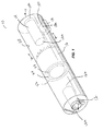
- FIG. 1 illustrates one embodiment of a device as contemplated herein.
- FIG. 2 illustrates a cross-sectional view of the device of FIG. 1 along 2-2.
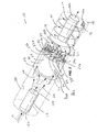
- FIG. 3 illustrates an embodiment of a device as contemplated herein.
- FIG. 4 illustrates a cross-sectional view of the device of FIG. 1 along 4-4.
- the disclosed devices further may be described by the following definitions and figures.
- the devices and elements disclosed herein may be "cylindrical” or “substantially cylindrical.”
- a device that is “cylindrical” or that is “substantially cylindrical” may have a maximum diameter in transverse cross-section (d max ) and a minimum diameter in transverse cross-section (d min ) meeting the equation ((d max - d min )/d max ⁇ 20%, 10%, 5%, or 0%.
- the devices and elements disclosed herein may be “frustoconical” or “substantially frustoconical.”
- frustoconical means having the shape of a cone or a frustrum, where a frustrum is the basal part of a cone formed by cutting off the top of the cone by a plane parallel to the base of the cone.
- FIG. 1 illustrates one embodiment of a device 10 as contemplated herein.
- the device 10 includes an upstream inlet 12 for receiving exhaust gas flow and a downstream outlet 14 for discharging exhaust gas flow.
- the device 10 further includes an acoustic silencer element 16 disposed between the upstream inlet 12 and the downstream outlet 14 for absorbing sound from the exhaust gas flow.
- the device 10 also includes a particle trap 18 having an opening 18b for collecting particulate matter 26 in the exhaust gas flow.
- the particle trap 18 is disposed downstream of the acoustic silencer element 16 on a wall 38 of the device 10.
- the acoustic silencer element 16 has an annular channel 20 permitting axial flow of gas therethrough from an upstream end of the annular channel through a downstream end of the annular channel.
- the downstream end of the annular channel 20 may be configured to have louvered openings 30 (see FIGS. 2-4 ) for discharging exhaust gas flow and imparting a spiral flow to the discharged gas flow (see, e.g., FIG. 3 ) such that the particulate matter 26 is forced radially outward via centrifugal force towards the wall 38 of the device 10 where the particulate matter 26 is collected in the particle trap 18 (see FIG. 3 ).
- the acoustic silencer element 16 of the device 10 includes an outer sound absorptive element 22 positioned adjacent to an inner wall 38 of the device 10 and forming a cylindrical sleeve. Also as illustrated in the figures, the acoustic silencer element 16 of the device 10 includes an inner sound absorptive element 24 positioned inside the outer sound absorptive element 22 and forming a cylindrical body. ( See FIGS. 1-3 ). The outer sound absorptive element 22 and the inner sound absorptive element 24 are spatially positioned relative to each other to form therebetween the annular channel 20 of the acoustic silencer element 16. ( See FIGS. 1-3 ).
- the illustrated acoustic silencer element 16 further includes a perforated cylindrical liner 42 positioned between the outer sound absorptive element 22 and the inner sound absorptive element 24.
- the perforated cylindrical liner 42 lines the annular channel 20. ( See FIG. 2 ).
- the perforated cylindrical liner 42 also supports an inner surface of the outer sound absorptive element 22 and supports an inner surface of the inner sound absorptive element 24 such that the outer sound absorptive element 22 and the inner sound absorptive element 24 are positioned in a spaced relationship to form the annular channel 20 therebetween.
- radial spokes 40 transversing the annular channel 20 and supporting the perforated cylindrical liner 42 and the spaced relationship of the outer sound absorptive element 22 and the inner sound absorptive element 24 ( See FIGS. 2 and 4 ).
- the outer sound absorptive element 22 of the acoustic silencing element 16 has an upstream surface and a downstream surface covered by solid rings (22a and 22b, respectively).
- the inner sound absorptive element 24 has an upstream surface covered by a solid flanged and dished head 24a, and the inner sound absorptive element 24 has a downstream surface covered by a solid circular plate 24b.
- the annular channel 20 is configured to have louvered openings 30 at a downstream end for discharging exhaust gas flow and imparting a spiral flow to the discharged gas flow.
- the louvered openings 30 are formed by: (i) an inner cylindrical frame having axial teeth 34, the axial teeth having peaks and valleys (34a, 34b); (ii) an outer cylindrical frame having axial teeth 32, the axial teeth having peaks and valleys (32a, 32b); and (iii) louvers 36 transversing the axial teeth of the inner cylindrical frame 34 and the axial teeth of the outer cylindrical frame 32. ( See FIGS. 3 and 4 ).
- the louvers 36 tranverse alternate planes defined by a peak and valley of an axial tooth of the inner cylindrical frame (34a-34b) and a plane defined by a peak and valley of an axial tooth of the outer cylindrical frame (32a-32b) in order to provide alternate louvered openings 30 at non-transerved positions.
- the particle trap 18 is present on a wall 38 of the device 10 and includes an opening 18a for collecting particulate matter 26 as it spirals around the wall 38 of the device 10.
- the particle trap 18 further includes a louvered deflector vane 18b for deflecting the particulate matter 26 into the opening 18a of the particle trap 18 as the particulate matter 26 is directly radially outward from the louvered openings 30.
- the diameter of the upstream inlet 12 may be less than the diameter of the device 10 such that exhaust gas flow expands as it exits the inlet 12 into the device 10. ( See FIG. 3 ).
- the downstream outlet 14 also may have a diameter that is less than the diameter of the device 10. ( See FIG. 3 ).
- the downstream outlet 14 is at least partially positioned inside of the device 10 such that the imparted spiral flow of exhaust gas exiting the louvered openings 30 is around the downstream outlet 14 in a circular manner.
- the downstream outlet 14 may have an upstream opening 14a for receiving exhaust gas flow where the upstream opening 14a is positioned upstream of the particle trap 18.
- particulate matter 26 is directed circularly around the downstream outlet 14 such that particulate matter 26 is directed into the opening 18a of particle trap 18 by the deflector vane 18b and not through the downstream opening 14b of the downstream outlet 14.
- particulate matter 26 is directed radially outward toward an inner surface of the wall 38 of the device 10 as exhaust containing the particulate matter 12 exits the louvered openings 30 at the downstream end of the annular channel 20.
- the annular channel 20 has a diameter that is less than the diameter of the device 10 such that particulate matter 26 present in exhaust gas exiting the louvered openings 30 at the downstream end of the annular channel 20 contacts the wall 38 of the device 10 ( See arrows 50 in FIG. 4 ).
- the invention as described provides a device comprising: an upstream inlet receiving exhaust gas flow; a downstream outlet discharging exhaust gas flow; a cylindrical body disposed between the upstream inlet and downstream outlet; and a particle trap having an opening for collecting particulate matter in the exhaust gas flow, the particle trap disposed downstream of the cylindrical body on a wall of the device; wherein the cylindrical body comprises an annular channel permitting axial flow of gas therethrough from an upstream end of the annular channel through a downstream end of the annular channel, the annular channel comprising flow deflecting devices for discharging exhaust gas flow and imparting a spiral flow to the discharged gas flow such that the particulate matter is forced radially outward via centrifugal force towards the wall of the device where the particulate matter is collected in the particle trap.
- the cylindrical body is an acoustic silencer element comprising: an outer sound absorptive element positioned adjacent to an inner wall of the device and forming a cylindrical or frustoconical sleeve; and an inner sound absorptive element positioned inside the outer sound absorptive element, the inner sound absorptive element forming a cylindrical or frustoconical body or sleeve; wherein the outer sound absorptive element and the inner sound absorptive element are spatially positioned relative to each other to form the annular channel therebetween.
- the outer sound absorptive element and the inner sound absorptive element may comprise absorptive material having a density of about 4-8 lbs/ft 3 .
- the absorptive material may comprise mineral wool or fiberglass.
- the device may further comprise a perforated liner positioned between the outer sound absorptive element and the inner sound absorptive element, the perforated liner supporting an inner surface of the outer sound absorptive element and the perforated liner supporting an inner surface of the inner sound absorptive element in a spaced relationship to form the annular channel therebetween.
- the perforated liner may have a surface area that is about 20-40% open.
- the perforated liner may comprise metal.
- the outer sound absorptive element has an upstream surface covered by a ring, and the outer sound absorptive element has a downstream surface covered by a ring.
- the rings may comprise metal.
- the inner sound absorptive element has an upstream surface covered by one of a circular plate, a flanged and dished head, or a cone, and the inner sound absorptive element has a downstream surface covered by a circular plate, a flanged and dished head, or a cone.
- the circular plates, the flanged and dished head, and the cone may comprise metal.
- the openings with flow deflecting devices form louvered openings.
- the louvered openings may be formed by (i) an inner cylindrical or frusto-conical frame; (ii) an outer cylindrical or frusto-conical frame; and (iii) louvers transversing the inner frame and the outer cylindrical frame.
- the inner frame comprises axial teeth having peaks and valleys
- the outer frame comprise axial teeth having peaks and valleys
- the louvers transverse alternate planes defined by a peak and valley of an axial tooth of the inner frame and a peak and valley of an axial tooth of the outer frame in order to provide alternate louvered openings at non-transversed planes.
- the inner frame, the outer frame, and the louvers may comprise metal and the louvers may be welded to the inner frame and the outer frame.
Landscapes
- Engineering & Computer Science (AREA)
- Chemical & Material Sciences (AREA)
- Combustion & Propulsion (AREA)
- Mechanical Engineering (AREA)
- General Engineering & Computer Science (AREA)
- Chemical Kinetics & Catalysis (AREA)
- Processes For Solid Components From Exhaust (AREA)
- Exhaust Silencers (AREA)
Abstract
Description
- The field of the invention relates to particulate arresting devices. In particular, the field of the invention relates to devices having low pressure drop, high efficiency spark or particulate arresting features and muffler features.
- Many muffler devices require a feature to separate solid particular matter from exhaust or gas flow. Such features sometimes are referred to as "spark arrestors" or "particle arrestors." Spark or particle separation or entrapment typically has been accomplished by utilizing internal piping arrangements to generate a centrifugal flow in an exhaust stream that separates carbon particulate matter from the stream based on the higher density of the particulate matter relative to gas in the stream. This piping typically results in an increased pressure drop, which consequently results in a decrease in engine or machine performance and an increase in energy consumption. For these reasons, muffler devices having a high particulate separation efficiency and low pressure drop are desirable.
- Disclosed are devices that include spark or particulate arresting features and optional muffler features. The disclosed devices may include: (a) an upstream inlet receiving exhaust gas flow; (b) a downstream outlet discharging exhaust gas flow; (c) a cylindrical body disposed between the upstream inlet and downstream outlet; and (d) a particle trap having an opening for collecting particulate matter in the exhaust gas flow, the particle trap disposed downstream of the cylindrical body on a wall of the device. The cylindrical body of the devices typically has an annular channel permitting axial flow of gas therethrough from an upstream end of the annular channel through a downstream end of the annular channel. The annular channel may be configured to impart a spiral flow to gas passing therethrough, for example via flow deflecting devices which may be positioned at the upstream end of the annular channel, at a downstream end of the annular channel, or between the upstream and downstream ends of the annular channel. As gas exits the annular channel, the particulate matter is forced radially outward via centrifugal force towards the wall of the device where the particulate matter is collected in the particle trap.
- In some embodiments, the cylindrical body of the devices is an acoustic silencer that includes: (i) an outer sound absorptive element positioned adjacent to an inner wall of the device and forming a cylindrical or frustoconical sleeve of sound absorptive material; and (ii) an inner sound absorptive element positioned inside the outer sound absorptive element, the inner sound absorptive element forming a cylindrical or frustoconical body or sleeve of sound absorptive material. The outer sound absorptive element and the inner sound absorptive element may be spatially positioned relative to each other to form the annular channel therebetween. The outer sound absorptive element and the inner sound absorptive element may comprise absorptive material having a density of about 4-8 lbs/ft3, including but not limited to mineral wool or fiberglass.
- In further embodiments, the acoustic silencer element further includes a perforated liner positioned between the outer sound absorptive element and the inner sound absorptive element. The perforated liner may form a cylindrical or frustoconical sleeve which lines the annular channel of the acoustic silencer element. Further, the perforated liner may support an inner surface of the outer sound absorptive element and the liner may support an inner surface of the inner sound absorptive element in a spaced relationship to form the annular channel therebetween. The perforated liner and may have a surface area that is about 20-40% open permitting access to supported sound absorptive material of the outer sound absorptive element and the inner sound absorptive element. The perforated liner may comprise material including but not limited to metal.
- In even further embodiments, the acoustic silencer element further includes radial spokes transversing the annular channel. The radial spokes may support the perforated liner and may support the spatial relationship of the outer sound absorptive element and the inner sound absorptive element which form the annular channel.
- The outer sound absorptive element of the acoustic silencing element may be covered or supported by additional structures. In some embodiments, the outer sound absorptive element has an upstream surface covered by a ring, which may be a solid ring, and the outer sound absorptive element has a downstream surface covered by a ring, which may be a solid ring. The rings may comprise material including but not limited to metal.
- The inner sound absorptive element of the acoustic silencing element may be covered or supported by additional structures. In some embodiments, the inner sound absorptive element has an upstream surface covered by a circular plate, a flanged and dished head, or a cone. In further embodiments, the inner sound absorptive element has a downstream surface covered by a circular plate. The circular plates, the solid flanged and dished head, and the cone may be solid and may comprise material including but not limited to metal.
- In the disclosed devices, the annular channel may be configured to impart a spiral flow to the discharged gas flow. For example, in some embodiments, the downstream end of the annular channel may include openings with flow deflecting devices which may include louvers. In some embodiments, the devices include louvered openings formed by: (i) an inner frame (e.g., an inner cylindrical or frustoconical frame), optionally having axial teeth, the axial teeth having peaks and valleys; (ii) an outer frame (e.g., an outer cylindrical or frustoconical frame), optionally having axial teeth, the axial teeth having peaks and valleys, and (iii) louvers transversing the inner frame and the outer frame, optionally at the axial teeth of the inner frame and the axial teeth of the outer frame. In further embodiments, the louvers may transverse alternate planes defined by a peak and valley of an axial tooth of the inner frame and a peak and valley of an axial tooth of the outer frame in order to provide alternate louvered openings at non-transversed planes. The inner frame, the outer frame, and the louvers may comprise material including but not limited to metal. In some embodiments, the inner frame, the outer frame, and the louvers comprise material, and the louvers are welded to the inner frame and the outer frame.
- The disclosed devices typically include a particle trap. In some embodiments, the particle trap comprises a louvered deflector vane for deflecting the particulate matter into the opening of the particle trap as the particulate matter is directly radially outward from the louvered openings.
- The disclosed devices typically include an upstream inlet and a downstream outlet. In some embodiments, the diameter of the upstream inlet is less than the diameter of the device such that exhaust gas flow expands as it exits the inlet into the device. The downstream outlet also may have a diameter that is less than the diameter of the device. In some embodiments, the downstream outlet is at least partially positioned inside of the device such that the imparted spiral flow of exhaust gas exiting the louvered opening is around the downstream outlet in a circular manner. In further embodiments, the downstream outlet may have an upstream opening for receiving exhaust gas flow where the upstream opening is positioned upstream of the particle trap. In such embodiments, particulate matter may be directed circularly around the downstream outlet such that particulate matter is forced into the particle trap and not through the downstream outlet.
- Also disclosed are methods for removing particulate matter from an exhaust stream. The methods include passing the exhaust stream through the presently disclosed devices and collecting particulate matter from the exhaust stream as the exhaust stream passes through the devices. In some embodiments of the methods, at least about 80%, 90%, 95%, 96%, 97%, 98%, 99%, or 100% of the particulate matter is removed from the exhaust stream as it passes through the devices. In further embodiments of the methods, the exhaust stream exhibits a pressure drop of less than about 1800, 1700, 1500, 1400, 1300, 1200, 1100, 1000, 900, 800, 700, 600, or 500 Pa as the exhaust stream passes through the device.
-
FIG. 1 illustrates one embodiment of a device as contemplated herein. -
FIG. 2 illustrates a cross-sectional view of the device ofFIG. 1 along 2-2. -
FIG. 3 illustrates an embodiment of a device as contemplated herein. -
FIG. 4 illustrates a cross-sectional view of the device ofFIG. 1 along 4-4. - Disclosed are devices having low pressure drop, high efficiency spark or particulate arresting features and muffler features. The disclosed devices further may be described by the following definitions and figures.
- Unless otherwise noted, the terms used herein are to be understood according to conventional usage by those of ordinary skill in the relevant art. In addition to the definitions of terms provided below, it is to be understood that as used in the specification, embodiments, and in the claims, "a", "an", or "the" can mean one or more, depending upon the context in which it is used. For example, "an element" should be interpreted to mean "one or more elements," depending upon the context in which it is used.
- As used herein, "about", "approximately," "substantially," and "significantly" will be understood by persons of ordinary skill in the art and will vary to some extent on the context in which they are used. If there are uses of the term which are not clear to persons of ordinary skill in the art given the context in which it is used, "about" and "approximately" will mean plus or minus ≤10% of the particular term and "substantially" and "significantly" will mean plus or minus >10% of the particular term, unless defined as otherwise herein.
- In some embodiments, the devices and elements disclosed herein may be "cylindrical" or "substantially cylindrical." In some embodiments, a device that is "cylindrical" or that is "substantially cylindrical" may have a maximum diameter in transverse cross-section (dmax) and a minimum diameter in transverse cross-section (dmin) meeting the equation ((dmax - dmin)/dmax ≤ 20%, 10%, 5%, or 0%.
- In some embodiments, the devices and elements disclosed herein may be "frustoconical" or "substantially frustoconical." As used herein, "frustoconical" means having the shape of a cone or a frustrum, where a frustrum is the basal part of a cone formed by cutting off the top of the cone by a plane parallel to the base of the cone.
- As used herein, the terms "include" and "including" have the same meaning as the terms "comprise" and "comprising." These terms should be interpreted to be "open-ended" unless otherwise specified. The terms "consisting of" or "consisting essentially of" should be interpreted to be "closed-ended" unless otherwise specified.
- Referring now to the figures,
FIG. 1 illustrates one embodiment of adevice 10 as contemplated herein. Thedevice 10 includes anupstream inlet 12 for receiving exhaust gas flow and adownstream outlet 14 for discharging exhaust gas flow. Thedevice 10 further includes anacoustic silencer element 16 disposed between theupstream inlet 12 and thedownstream outlet 14 for absorbing sound from the exhaust gas flow. Thedevice 10 also includes aparticle trap 18 having an opening 18b for collectingparticulate matter 26 in the exhaust gas flow. Theparticle trap 18 is disposed downstream of theacoustic silencer element 16 on awall 38 of thedevice 10. Theacoustic silencer element 16 has anannular channel 20 permitting axial flow of gas therethrough from an upstream end of the annular channel through a downstream end of the annular channel. The downstream end of theannular channel 20 may be configured to have louvered openings 30 (seeFIGS. 2-4 ) for discharging exhaust gas flow and imparting a spiral flow to the discharged gas flow (see, e.g.,FIG. 3 ) such that theparticulate matter 26 is forced radially outward via centrifugal force towards thewall 38 of thedevice 10 where theparticulate matter 26 is collected in the particle trap 18 (seeFIG. 3 ). - As illustrated is the figures, the
acoustic silencer element 16 of thedevice 10 includes an outer soundabsorptive element 22 positioned adjacent to aninner wall 38 of thedevice 10 and forming a cylindrical sleeve. Also as illustrated in the figures, theacoustic silencer element 16 of thedevice 10 includes an inner soundabsorptive element 24 positioned inside the outer soundabsorptive element 22 and forming a cylindrical body. (SeeFIGS. 1-3 ). The outer soundabsorptive element 22 and the inner soundabsorptive element 24 are spatially positioned relative to each other to form therebetween theannular channel 20 of theacoustic silencer element 16. (SeeFIGS. 1-3 ). - The illustrated
acoustic silencer element 16 further includes a perforated cylindrical liner 42 positioned between the outer soundabsorptive element 22 and the inner soundabsorptive element 24. The perforated cylindrical liner 42 lines theannular channel 20. (SeeFIG. 2 ). The perforated cylindrical liner 42 also supports an inner surface of the outer soundabsorptive element 22 and supports an inner surface of the inner soundabsorptive element 24 such that the outer soundabsorptive element 22 and the inner soundabsorptive element 24 are positioned in a spaced relationship to form theannular channel 20 therebetween. Also illustrated areradial spokes 40 transversing theannular channel 20 and supporting the perforated cylindrical liner 42 and the spaced relationship of the outer soundabsorptive element 22 and the inner sound absorptive element 24 (SeeFIGS. 2 and4 ). - As illustrated in
FIGS. 2 and3 , the outer soundabsorptive element 22 of the acoustic silencingelement 16 has an upstream surface and a downstream surface covered by solid rings (22a and 22b, respectively). Also as illustrated inFIGS. 2 and3 , the inner soundabsorptive element 24 has an upstream surface covered by a solid flanged and dishedhead 24a, and the inner soundabsorptive element 24 has a downstream surface covered by a solidcircular plate 24b. - As illustrated in
FIG. 3 , theannular channel 20 is configured to havelouvered openings 30 at a downstream end for discharging exhaust gas flow and imparting a spiral flow to the discharged gas flow. Thelouvered openings 30 are formed by: (i) an inner cylindrical frame havingaxial teeth 34, the axial teeth having peaks and valleys (34a, 34b); (ii) an outer cylindrical frame havingaxial teeth 32, the axial teeth having peaks and valleys (32a, 32b); and (iii)louvers 36 transversing the axial teeth of the innercylindrical frame 34 and the axial teeth of the outercylindrical frame 32. (SeeFIGS. 3 and4 ). Thelouvers 36 tranverse alternate planes defined by a peak and valley of an axial tooth of the inner cylindrical frame (34a-34b) and a plane defined by a peak and valley of an axial tooth of the outer cylindrical frame (32a-32b) in order to provide alternatelouvered openings 30 at non-transerved positions. - As illustrated in
FIG. 3 , theparticle trap 18 is present on awall 38 of thedevice 10 and includes anopening 18a for collectingparticulate matter 26 as it spirals around thewall 38 of thedevice 10. Theparticle trap 18 further includes a louvered deflector vane 18b for deflecting theparticulate matter 26 into theopening 18a of theparticle trap 18 as theparticulate matter 26 is directly radially outward from thelouvered openings 30. - In the disclosed
device 10, the diameter of theupstream inlet 12 may be less than the diameter of thedevice 10 such that exhaust gas flow expands as it exits theinlet 12 into thedevice 10. (SeeFIG. 3 ). Thedownstream outlet 14 also may have a diameter that is less than the diameter of thedevice 10. (SeeFIG. 3 ). - As illustrated in
FIG. 3 , thedownstream outlet 14 is at least partially positioned inside of thedevice 10 such that the imparted spiral flow of exhaust gas exiting thelouvered openings 30 is around thedownstream outlet 14 in a circular manner. Also as illustrated inFIG. 3 , thedownstream outlet 14 may have an upstream opening 14a for receiving exhaust gas flow where the upstream opening 14a is positioned upstream of theparticle trap 18. In this configuration,particulate matter 26 is directed circularly around thedownstream outlet 14 such thatparticulate matter 26 is directed into theopening 18a ofparticle trap 18 by the deflector vane 18b and not through the downstream opening 14b of thedownstream outlet 14. - As illustrated in
FIG. 4 ,particulate matter 26 is directed radially outward toward an inner surface of thewall 38 of thedevice 10 as exhaust containing theparticulate matter 12 exits thelouvered openings 30 at the downstream end of theannular channel 20. As illustrated inFIG. 4 , theannular channel 20 has a diameter that is less than the diameter of thedevice 10 such thatparticulate matter 26 present in exhaust gas exiting thelouvered openings 30 at the downstream end of theannular channel 20 contacts thewall 38 of the device 10 (Seearrows 50 inFIG. 4 ). - Accordingly, the invention as described provides a device comprising: an upstream inlet receiving exhaust gas flow; a downstream outlet discharging exhaust gas flow; a cylindrical body disposed between the upstream inlet and downstream outlet; and a particle trap having an opening for collecting particulate matter in the exhaust gas flow, the particle trap disposed downstream of the cylindrical body on a wall of the device; wherein the cylindrical body comprises an annular channel permitting axial flow of gas therethrough from an upstream end of the annular channel through a downstream end of the annular channel, the annular channel comprising flow deflecting devices for discharging exhaust gas flow and imparting a spiral flow to the discharged gas flow such that the particulate matter is forced radially outward via centrifugal force towards the wall of the device where the particulate matter is collected in the particle trap.
- Advantageously, the cylindrical body is an acoustic silencer element comprising: an outer sound absorptive element positioned adjacent to an inner wall of the device and forming a cylindrical or frustoconical sleeve; and an inner sound absorptive element positioned inside the outer sound absorptive element, the inner sound absorptive element forming a cylindrical or frustoconical body or sleeve; wherein the outer sound absorptive element and the inner sound absorptive element are spatially positioned relative to each other to form the annular channel therebetween.
- The outer sound absorptive element and the inner sound absorptive element may comprise absorptive material having a density of about 4-8 lbs/ft3. The absorptive material may comprise mineral wool or fiberglass.
- The device may further comprise a perforated liner positioned between the outer sound absorptive element and the inner sound absorptive element, the perforated liner supporting an inner surface of the outer sound absorptive element and the perforated liner supporting an inner surface of the inner sound absorptive element in a spaced relationship to form the annular channel therebetween.
- For example, the perforated liner may have a surface area that is about 20-40% open. The perforated liner may comprise metal.
- Conveniently, the outer sound absorptive element has an upstream surface covered by a ring, and the outer sound absorptive element has a downstream surface covered by a ring. For example, the rings may comprise metal.
- Preferably, the inner sound absorptive element has an upstream surface covered by one of a circular plate, a flanged and dished head, or a cone, and the inner sound absorptive element has a downstream surface covered by a circular plate, a flanged and dished head, or a cone. The circular plates, the flanged and dished head, and the cone may comprise metal.
- Advantageously, the openings with flow deflecting devices form louvered openings. For example, the louvered openings may be formed by (i) an inner cylindrical or frusto-conical frame; (ii) an outer cylindrical or frusto-conical frame; and (iii) louvers transversing the inner frame and the outer cylindrical frame.
- In a preferred embodiment, the inner frame comprises axial teeth having peaks and valleys, the outer frame comprise axial teeth having peaks and valleys, and the louvers transverse alternate planes defined by a peak and valley of an axial tooth of the inner frame and a peak and valley of an axial tooth of the outer frame in order to provide alternate louvered openings at non-transversed planes. For example, the inner frame, the outer frame, and the louvers may comprise metal and the louvers may be welded to the inner frame and the outer frame.
- In the foregoing description, it will be readily apparent to one skilled in the art that varying substitutions and modifications may be made to the invention disclosed herein without departing from the scope and spirit of the invention. The invention illustratively described herein suitably may be practiced in the absence of any element or elements, limitation or limitations which is not specifically disclosed herein. The terms and expressions which have been employed are used as terms of description and not of limitation, and there is no intention that in the use of such terms and expressions of excluding any equivalents of the features shown and described or portions thereof, but it is recognized that various modifications are possible within the scope of the invention. Thus, it should be understood that although the present invention has been illustrated by specific embodiments and optional features, modification and/or variation of the concepts herein disclosed may be resorted to by those skilled in the art, and that such modifications and variations are considered to be within the scope of this invention.
Claims (15)
- A device comprising:(a) an upstream inlet receiving exhaust gas flow;(b) a downstream outlet discharging exhaust gas flow;(c) a cylindrical body disposed between the upstream inlet and downstream outlet; and(d) a particle trap having an opening for collecting particulate matter in the exhaust gas flow, the particle trap disposed downstream of the cylindrical body on a wall of the device;
wherein the cylindrical body comprises an annular channel permitting axial flow of gas therethrough from an upstream end of the annular channel through a downstream end of the annular channel, the annular channel comprising flow deflecting devices for discharging exhaust gas flow and imparting a spiral flow to the discharged gas flow such that the particulate matter is forced radially outward via centrifugal force towards the wall of the device where the particulate matter is collected in the particle trap. - The device of claim 1, wherein the flow deflecting devices are positioned at the upstream end of the annular channel, at the downstream end of the annular channel, or in between the upstream end and the downstream end of the annular channel.
- The device of claim 1, wherein the cylindrical body is an acoustic silencer element comprising:(i) an outer sound absorptive element positioned adjacent to an inner wall of the device and forming a cylindrical or frustoconical sleeve;(ii) an inner sound absorptive element positioned inside the outer sound absorptive element, the inner sound absorptive element forming a cylindrical or frustoconical body or sleeve;
wherein the outer sound absorptive element and the inner sound absorptive element are spatially positioned relative to each other to form the annular channel therebetween. - The device of claim 3, further comprising a perforated liner positioned between the outer sound absorptive element and the inner sound absorptive element, the perforated liner supporting an inner surface of the outer sound absorptive element and the perforated liner supporting an inner surface of the inner sound absorptive element in a spaced relationship to form the annular channel therebetween.
- The device of claim 4, further comprising radial spokes transversing the annular channel and supporting the perforated liner.
- The device of claim 3, wherein the outer sound absorptive element has an upstream surface covered by a ring, and the outer sound absorptive element has a downstream surface covered by a ring.
- The device of claim 3, wherein the inner sound absorptive element has an upstream surface covered by one of a circular plate, a flanged and dished head, or a cone, and the inner sound absorptive element has a downstream surface covered by a circular plate, a flanged and dished head, or a cone.
- The device of claim 1, wherein the openings with flow deflecting devices form louvered openings.
- The device of claim 8, wherein the louvered openings are formed by(i) an inner cylindrical or frustoconical frame;(ii) an outer cylindrical or frustoconical frame;(iii) louvers transversing the inner frame and the outer cylindrical frame.
- The device of claim 9, wherein the inner frame comprises axial teeth having peaks and valleys, the outer frame comprise axial teeth having peaks and valleys, and the louvers transverse alternate planes defined by a peak and valley of an axial tooth of the inner frame and a peak and valley of an axial tooth of the outer frame in order to provide alternate louvered openings at non-transversed planes.
- The device of claim 1, wherein the particle trap comprises a louvered deflector vane for deflecting the particulate matter into the opening of the particle trap.
- The device of claim 1, wherein the device and the upstream inlet having diameters such that the diameter of the upstream inlet is less than the diameter of the diameter of the device and exhaust gas flow expands as it exits the inlet into the device.
- The device of claim 1, wherein the downstream outlet is at least partially positioned inside of the device such that the imparted spiral flow is around the downstream outlet.
- The device of claim 13, wherein the downstream outlet has an upstream opening for receiving exhaust gas flow, the upstream opening being positioned upstream of the particle trap.
- A method for removing particulate matter from an exhaust stream, the method comprising passing the exhaust stream through the device of claim 1, wherein at least about 80% of the particulate matter is removed from the exhaust stream.
Applications Claiming Priority (1)
| Application Number | Priority Date | Filing Date | Title |
|---|---|---|---|
| US13/653,058 US9121319B2 (en) | 2012-10-16 | 2012-10-16 | Low pressure drop, high efficiency spark or particulate arresting devices and methods of use |
Publications (1)
| Publication Number | Publication Date |
|---|---|
| EP2722501A1 true EP2722501A1 (en) | 2014-04-23 |
Family
ID=49301311
Family Applications (1)
| Application Number | Title | Priority Date | Filing Date |
|---|---|---|---|
| EP20130186255 Withdrawn EP2722501A1 (en) | 2012-10-16 | 2013-09-26 | Low pressure drop, high efficiency spark or particulate arresting devices and methods of use |
Country Status (2)
| Country | Link |
|---|---|
| US (1) | US9121319B2 (en) |
| EP (1) | EP2722501A1 (en) |
Families Citing this family (10)
| Publication number | Priority date | Publication date | Assignee | Title |
|---|---|---|---|---|
| EP2720822B1 (en) * | 2011-06-16 | 2019-07-31 | Plymovent Group B.V. | Particle pre-separator for removing particles from a flow of gas mixture ; air cleaning system and gas treatment system comprising such pre-separator |
| US9108136B2 (en) * | 2013-02-13 | 2015-08-18 | Camfil Usa, Inc. | Dust collector with spark arrester |
| USD767456S1 (en) * | 2015-02-05 | 2016-09-27 | V&H Performance, Llc | Exhaust muffler |
| CN105854428A (en) * | 2016-05-26 | 2016-08-17 | 北京龙腾华创环境能源技术有限公司 | Multistage spiral-flow type ultra-clean dust removal device |
| US10639750B2 (en) | 2017-04-14 | 2020-05-05 | Felix Sorkin | Spark capture system for use with cutting torch |
| RU2659701C1 (en) * | 2017-07-05 | 2018-07-03 | Акционерное общество "Управляющая компания "Брянский машиностроительный завод" (АО "УК "БМЗ") | Spark arrester for exhaust gases of internal combustion engine |
| CN109499190B (en) * | 2018-09-28 | 2021-06-25 | 长沙吉天环保科技有限公司 | Primary effect preprocessor |
| US20200109713A1 (en) * | 2018-10-09 | 2020-04-09 | Hi-Bar Blowers, Inc. | Integrated rotary positive-displacement machinery |
| US11154873B2 (en) * | 2019-09-19 | 2021-10-26 | X'pole Precision Tools Inc. | Multi-cyclonic dust filter device |
| US11253874B2 (en) * | 2019-09-19 | 2022-02-22 | X'pole Precision Tools Inc. | Cyclonic dust filter device |
Citations (2)
| Publication number | Priority date | Publication date | Assignee | Title |
|---|---|---|---|---|
| US4311494A (en) * | 1977-09-26 | 1982-01-19 | Facet Enterprises, Inc. | Axial flow gas cleaning device |
| WO2009087270A1 (en) * | 2008-01-09 | 2009-07-16 | Wärtsilä Finland Oy | Exhaust silencer |
Family Cites Families (170)
| Publication number | Priority date | Publication date | Assignee | Title |
|---|---|---|---|---|
| US246038A (en) | 1881-08-23 | Reflector | ||
| US1304096A (en) | 1919-05-20 | John j | ||
| US35237A (en) | 1862-05-13 | Improved automatic boiler-feeder | ||
| US2732032A (en) | 1956-01-24 | sandison | ||
| US2463A (en) | 1842-02-21 | Spark-arrester | ||
| US429347A (en) | 1890-06-03 | Dust-collector | ||
| US970397A (en) | 1909-12-01 | 1910-09-13 | Charles A Rush | Spark-arrester. |
| US1037326A (en) | 1911-11-17 | 1912-09-03 | Nickolas J Roether | Spark-arrester. |
| US1215935A (en) | 1915-11-22 | 1917-02-13 | Milton L Hickman | Separator. |
| US1784627A (en) | 1924-03-18 | 1930-12-09 | Hamill James | Apparatus for separating moisture from vapor |
| US1840862A (en) | 1928-12-20 | 1932-01-12 | Sr Jean Francis Webb | Exhaust treating apparatus |
| US2511190A (en) | 1945-10-04 | 1950-06-13 | Centrifix Corp | Baffle type muffler |
| BE486957A (en) | 1948-01-26 | |||
| US2646854A (en) | 1948-09-22 | 1953-07-28 | Walker George Bromhead | Baffle type muffler having a plurality of helical passages |
| US2662610A (en) | 1950-08-04 | 1953-12-15 | Oswald X Heinrich | Apparatus for centrifugal separation of suspended particles |
| US2925884A (en) | 1956-07-13 | 1960-02-23 | Centrifix Corp | Line purifier construction |
| US2886121A (en) * | 1956-10-25 | 1959-05-12 | John T Welbourn | Air-cooled silencer |
| US3064411A (en) | 1959-08-14 | 1962-11-20 | Jr Joseph Breslove | Separator |
| US3009539A (en) | 1960-03-07 | 1961-11-21 | Rockwell Standard Co | Spark arrester |
| US3216182A (en) | 1964-10-06 | 1965-11-09 | Gen Electric | Axial flow vapor-liquid separator |
| US3374857A (en) | 1966-12-29 | 1968-03-26 | Hugh A. Hutchins | Muffler construction |
| US3407575A (en) | 1967-12-08 | 1968-10-29 | Krizman John | Through-flow spark arrester |
| US3498233A (en) | 1968-02-15 | 1970-03-03 | Ormco Corp | Vane pump |
| US3545179A (en) | 1968-06-25 | 1970-12-08 | Nelson Muffler Corp | Silencer |
| US3687225A (en) | 1971-04-06 | 1972-08-29 | Nelson Muffler Corp | Combined exhaust muffler with spark arrester |
| US3805495A (en) | 1971-06-28 | 1974-04-23 | J Steel | Apparatus for removing particles from a gaseous stream |
| US3779340A (en) | 1972-10-10 | 1973-12-18 | Enviro Acoustic R & D Inc | Muffler and spark arrestor for internal combustion engine |
| US3957471A (en) | 1973-12-21 | 1976-05-18 | Hoei Kogyo Kabushiki Kaisha | Exhaust gas purifier |
| US3947731A (en) | 1974-01-01 | 1976-03-30 | Manufactura de Articulos para el Hogar "Aurora" Sociedad Anonima Industrial Comercial, Inmobiliaria y Financiera | Piezoelectric lighter |
| US3969895A (en) | 1974-06-24 | 1976-07-20 | John Krizman | Power control valve attachment for two cycle motorcycle type engine exhaust systems |
| US3958967A (en) | 1974-08-02 | 1976-05-25 | Bassani Manufacturing | Motocycle spark arrestor |
| FR2287014A1 (en) | 1974-10-04 | 1976-04-30 | Bicosa Recherches | IMPROVEMENTS TO AUTOMATIC CONTROL DEVICES, ACCORDING TO A PARAMETER, OF A GAS FUEL APPLIANCE |
| US3945331A (en) | 1975-01-23 | 1976-03-23 | Enertherm, Inc. | Thermal recovery system |
| US4011922A (en) | 1975-07-18 | 1977-03-15 | Nelson Industries, Inc. | Muffler construction |
| GB1571710A (en) | 1977-10-21 | 1980-07-16 | Veenendaal J | Dehulling of cocoa beans |
| US4259941A (en) | 1978-02-01 | 1981-04-07 | Sadie M. Northwood | Fireplace construction for mobile homes |
| US4241719A (en) | 1978-03-17 | 1980-12-30 | Vickery Joseph K | Heater stove apparatus |
| US4147230A (en) | 1978-04-14 | 1979-04-03 | Nelson Industries, Inc. | Combination spark arrestor and aspirating muffler |
| US4222349A (en) | 1978-04-24 | 1980-09-16 | Kadan Bertram Z | Stack exhaust heat recycling system |
| JPS6246416Y2 (en) | 1978-04-27 | 1987-12-15 | ||
| IT7853327V0 (en) | 1978-05-17 | 1978-05-17 | Fiat Spa | EXHAUST SILENCER FOR AGRICULTURAL TRACTORS |
| US4226224A (en) | 1978-06-19 | 1980-10-07 | Milligan Orley B | Wood burning stove for heating homes |
| US4198856A (en) | 1978-08-11 | 1980-04-22 | Appleton Joseph H | Smoke bomb isolation and containment device |
| US4180052A (en) | 1978-10-19 | 1979-12-25 | Henderson Delbert H | Furnace fireplace apparatus having separate combustion and heating air systems and settling chambers for particulate matter |
| US4370855A (en) | 1979-06-25 | 1983-02-01 | Emerson Electric Co. | Muffler for portable engine |
| US4317502A (en) | 1979-10-22 | 1982-03-02 | Harris Theodore R | Engine exhaust muffler |
| US4271815A (en) | 1979-11-08 | 1981-06-09 | Chinook Manufacturing Co. | Prefabricated fireplace for permanent installation |
| US4409946A (en) | 1980-01-25 | 1983-10-18 | Vaporpak Pty. Limited | Internal combustion engines |
| US4325460A (en) | 1980-04-14 | 1982-04-20 | Donaldson Company, Inc. | Ejector muffler |
| US4385623A (en) | 1980-09-22 | 1983-05-31 | Simpson-Duravent | Flue pipe for fireplace stove |
| US4637792A (en) | 1980-12-22 | 1987-01-20 | Arkansas Patents, Inc. | Pulsing combustion |
| US4348466A (en) | 1981-01-27 | 1982-09-07 | Varta Batteries Limited | Anti-spill device for electrolyte battery |
| US4424882A (en) | 1981-02-09 | 1984-01-10 | Moller Paul S | Resonator type mufflers |
| FR2502789A1 (en) | 1981-03-26 | 1982-10-01 | Singer Edouard | IMPROVEMENT TO PORTABLE VOLTAGE ABSENCE VERIFICATION DEVICES ON HIGH VOLTAGE HIGH VOLTAGE INSTALLATIONS |
| US4330372A (en) | 1981-05-29 | 1982-05-18 | National Steel Corporation | Coke oven emission control method and apparatus |
| US4400754A (en) | 1981-11-27 | 1983-08-23 | Esquire, Inc. | Spark arrestor |
| US4553528A (en) | 1982-01-04 | 1985-11-19 | Wells William T | Free-standing stove and fireplace apparatus |
| US4487289A (en) | 1982-03-01 | 1984-12-11 | Nelson Industries, Inc. | Exhaust muffler with protective shield |
| US4450932A (en) | 1982-06-14 | 1984-05-29 | Nelson Industries, Inc. | Heat recovery muffler |
| US4580657A (en) | 1983-06-16 | 1986-04-08 | Donaldson Company, Inc. | Integral fluted tube for sound suppression and exhaust ejection |
| US4569329A (en) | 1984-02-01 | 1986-02-11 | The Coleman Company, Inc. | Reflector for radiant heater |
| US4624241A (en) | 1984-02-01 | 1986-11-25 | The Coleman Company, Inc. | Reflector for radiant heater |
| US4782814A (en) | 1984-02-01 | 1988-11-08 | The Coleman Company, Inc. | Burner for radiant heater |
| US4632216A (en) | 1984-06-27 | 1986-12-30 | Donaldson Company, Inc. | Muffler apparatus and method for making same |
| US4608963A (en) | 1985-01-04 | 1986-09-02 | Simpson Dura Vent Company, Inc. | Thermally balanced air flow chimney |
| US4727828A (en) | 1985-03-29 | 1988-03-01 | Komatsu Zenoah Company | Portable engine unit |
| US4711032A (en) | 1985-09-05 | 1987-12-08 | Delta International Machinery Corp. | Portable saw mill |
| US4780076A (en) | 1985-10-11 | 1988-10-25 | Arkansas Patents, Inc. | Power burner |
| US4651712A (en) | 1985-10-11 | 1987-03-24 | Arkansas Patents, Inc. | Pulsing combustion |
| US4727617A (en) | 1985-12-09 | 1988-03-01 | Bardini Armando J | Chimney cleaning apparatus |
| US4809666A (en) | 1986-01-21 | 1989-03-07 | Outboard Marine Corporation | Fuel feed system |
| US4815430A (en) | 1986-03-26 | 1989-03-28 | Komatsu Zenoah Company | Portable engine unit |
| US4909948A (en) | 1986-09-19 | 1990-03-20 | Eichelberger Sr Philip T | Above ground waste water disposal system |
| US4867768A (en) | 1987-08-21 | 1989-09-19 | Donaldson Company, Inc. | Muffler apparatus with filter trap and method of use |
| US4851015A (en) | 1987-08-21 | 1989-07-25 | Donaldson Company, Inc. | Muffler apparatus with filter trap and method of use |
| US4816042A (en) | 1987-09-25 | 1989-03-28 | Baker International Corporation | Scrubber-exhaust gas conditioner |
| GB8824276D0 (en) | 1988-10-17 | 1988-11-23 | Telektron Ltd | Pressuring & purging apparatus |
| US5123501A (en) | 1988-10-21 | 1992-06-23 | Donaldson Company, Inc. | In-line constricted sound-attenuating system |
| JPH0639903B2 (en) | 1988-11-15 | 1994-05-25 | 本田技研工業株式会社 | Engine generator |
| US5058704A (en) | 1988-11-21 | 1991-10-22 | Yu Chuen Huan | Turbo jet muffler |
| US5156114A (en) | 1989-11-22 | 1992-10-20 | Gunnerman Rudolf W | Aqueous fuel for internal combustion engine and method of combustion |
| US5159884A (en) | 1990-07-02 | 1992-11-03 | Malick Franklin S | Automatic incinerator apparatus |
| US5564588A (en) | 1990-09-21 | 1996-10-15 | Ace Tank & Equipment Company | Method and storage tank system for aboveground storage of flammable liquids |
| US5251473A (en) | 1990-09-21 | 1993-10-12 | Ace Tank & Equipment Company | Method and storage tank system for aboveground storage of flammable liquids |
| US5107698A (en) | 1991-04-05 | 1992-04-28 | Leslie Gilliam | Smoke generating apparatus and method for in situ vacuum leak detection |
| US5177962A (en) | 1992-01-14 | 1993-01-12 | Tecumseh Products Company | External spark arrestor |
| US5250094A (en) | 1992-03-16 | 1993-10-05 | Donaldson Company, Inc. | Ceramic filter construction and method |
| USD343700S (en) | 1992-05-04 | 1994-01-25 | New England Ventilation Technologies | Spark arrestor apparatus |
| US5451728A (en) | 1992-11-19 | 1995-09-19 | Wci Outdoor Products, Inc. | Muffler for two-cycle internal combustion engine and method of assembly |
| US5325841A (en) | 1993-02-05 | 1994-07-05 | Hooper Sr Virgil | Barbecue apparatus and method |
| US5434407A (en) | 1993-08-23 | 1995-07-18 | Gentex Corporation | Automatic rearview mirror incorporating light pipe |
| US5431706A (en) | 1993-10-05 | 1995-07-11 | Dry Systems Technologies | Disposable particulate filter |
| JP3373942B2 (en) | 1994-07-27 | 2003-02-04 | 本田技研工業株式会社 | Exhaust silencer |
| US5555876A (en) | 1994-10-17 | 1996-09-17 | Francisco, Jr.; Richard V. | Chimney safety and control system |
| US5521339A (en) | 1994-11-18 | 1996-05-28 | Wci Outdoor Products, Inc. | Catalyst muffler system |
| US5623958A (en) | 1995-02-22 | 1997-04-29 | Bumpers; Norman R. | Low pressure relief valve |
| US5558079A (en) | 1995-07-07 | 1996-09-24 | Diamond G Progressive Enterprises, Inc. | Trash incinerator |
| US6199345B1 (en) | 1995-09-27 | 2001-03-13 | Gary A. Dean | Method and apparatus for seismically retrofitting a household chimney |
| US5809989A (en) | 1996-02-28 | 1998-09-22 | Dacotah Rose, Inc. | Apparatus and method to prevent campfires from spreading |
| US6355904B1 (en) | 1996-06-07 | 2002-03-12 | Science Applications International Corporation | Method and system for high-temperature waste treatment |
| US5785046A (en) | 1996-08-09 | 1998-07-28 | Colla; Gregory D. | Portable fire pit |
| US5753800A (en) | 1997-01-16 | 1998-05-19 | Gilliam; Leslie | Smoke generating apparatus for in situ exhaust leak detection |
| US6263851B1 (en) | 1997-03-07 | 2001-07-24 | Yamaha Hatsudoki Kabushiki Kaisha | Air inlet device for watercraft engine |
| JP3920406B2 (en) | 1997-05-21 | 2007-05-30 | ヤマハ発動機株式会社 | Small ship |
| US5904042A (en) | 1997-08-28 | 1999-05-18 | Rohrbaugh; David | Diesel exhaust conditioning system |
| US5916136A (en) | 1997-10-02 | 1999-06-29 | Ettere; Mark | Aspiration device for vehicle engine exhaust system |
| US6238622B1 (en) | 1997-12-05 | 2001-05-29 | Rosemount Analytical Inc. | Flame ionization detector |
| US6012285A (en) | 1998-03-19 | 2000-01-11 | Wacker Corporation | Exhaust pipe with improved drain |
| US6047767A (en) | 1998-04-21 | 2000-04-11 | Vita International, Inc. | Heat exchanger |
| US6119638A (en) | 1998-05-13 | 2000-09-19 | Kennedy; Gino W. | Diesel powered generator cooling-water pump |
| US6152817A (en) | 1998-06-23 | 2000-11-28 | Gelco Manufacturing, Inc. | Chimney cover |
| US6062922A (en) | 1998-10-30 | 2000-05-16 | Yamaha Hatsudoki Kabushiki Kaisha | Watercraft propulsion system |
| US6698394B2 (en) | 1999-03-23 | 2004-03-02 | Thomas Engine Company | Homogenous charge compression ignition and barrel engines |
| US7469662B2 (en) | 1999-03-23 | 2008-12-30 | Thomas Engine Company, Llc | Homogeneous charge compression ignition engine with combustion phasing |
| DE10020373A1 (en) | 2000-04-26 | 2001-10-31 | Stihl Maschf Andreas | Exhaust silencer with spark screen |
| US6591935B1 (en) | 2000-07-17 | 2003-07-15 | Gary L. Petley | ATV stealth exhaust system |
| ATE347024T1 (en) | 2000-12-20 | 2006-12-15 | Quiet Storm Llc | DEVICE FOR IMPROVED NOISE ATTENUATION IN AN ABSORPTION DAMPER OF AN INTERNAL COMBUSTION ENGINE |
| US6467569B2 (en) | 2001-01-19 | 2002-10-22 | Supertrapp Industries | Spark arresting muffler with exhaust path parallel to muffler centerline |
| US6467570B1 (en) | 2001-05-15 | 2002-10-22 | Arvin Technologies, Inc. | Spark arrester with spark filter |
| JP4138275B2 (en) | 2001-07-23 | 2008-08-27 | エキサイド インダストリーズ リミテッド | Electrolyte leakage resistance automotive battery |
| US6540046B1 (en) | 2001-08-06 | 2003-04-01 | Nelson Industries, Inc. | Compact economical spark arrestor and muffler |
| US7726444B1 (en) | 2001-08-31 | 2010-06-01 | Laughlin James C | Exhaust system baffle apparatus |
| US7438003B2 (en) | 2001-10-03 | 2008-10-21 | Wilfer Ronald R | Burning container |
| US6758875B2 (en) | 2001-11-13 | 2004-07-06 | Great Lakes Air Systems, Inc. | Air cleaning system for a robotic welding chamber |
| CA2381497A1 (en) | 2002-01-02 | 2003-08-01 | Peter F. Crombeen | Exhaust gas muffler |
| US6712888B2 (en) | 2002-06-24 | 2004-03-30 | Albert F. Siska | Engine emission control system and method |
| US6933931B2 (en) | 2002-08-23 | 2005-08-23 | Ceronix, Inc. | Method and apparatus of position location |
| AU2003284386A1 (en) | 2002-10-31 | 2004-06-07 | White Brothers Performance Products, Inc. | Muffler with spark arrestor |
| US20040200665A1 (en) | 2003-04-08 | 2004-10-14 | Adams Gar M | Exhaust system for V-twin engines |
| US7482705B2 (en) | 2003-05-12 | 2009-01-27 | Piercey Iii Gerald S | Generator support plenum |
| US8132646B2 (en) | 2003-08-06 | 2012-03-13 | Andreas Stihl Ag & Co. Kg | Exhaust gas muffler |
| DE10335864B4 (en) | 2003-08-06 | 2014-12-04 | Andreas Stihl Ag & Co. Kg | exhaust silencer |
| US7282077B2 (en) | 2003-10-24 | 2007-10-16 | Briggs & Stratton Corporation | Air cleaner assembly |
| CN100379639C (en) | 2004-03-31 | 2008-04-09 | 本田技研工业株式会社 | all terrain vehicle |
| US7156202B2 (en) | 2004-04-05 | 2007-01-02 | Mtd Products Inc | Method and apparatus for venting exhaust gas from an engine |
| JP4381868B2 (en) | 2004-04-07 | 2009-12-09 | 本田技研工業株式会社 | Exhaust muffler with engine exhaust purification function |
| SE527104C2 (en) * | 2004-05-21 | 2005-12-20 | Alstom Technology Ltd | Method and apparatus for separating dust particles |
| US20050263344A1 (en) | 2004-05-27 | 2005-12-01 | Warfel Paul A | Exhaust gas muffler |
| EP1781907B1 (en) | 2004-05-28 | 2009-07-29 | Silentor Holding A/S | Combination silencer |
| USD534111S1 (en) | 2004-08-09 | 2006-12-26 | Advanced Car Specialties Limited | Spark arrestor |
| JP4383294B2 (en) | 2004-09-06 | 2009-12-16 | 本田技研工業株式会社 | Saddle riding vehicle |
| WO2006029199A1 (en) | 2004-09-08 | 2006-03-16 | Donaldson Company, Inc. | Joint for an engine exhaust system component |
| US6913011B1 (en) | 2004-09-08 | 2005-07-05 | Ronald B. Snider | Tapered grill, smoker and fireplace device |
| JP4391377B2 (en) | 2004-09-30 | 2009-12-24 | 本田技研工業株式会社 | Muffler mounting structure |
| DE102004054966A1 (en) | 2004-11-13 | 2006-05-18 | Andreas Stihl Ag & Co. Kg | exhaust silencer |
| US20060157295A1 (en) | 2005-01-14 | 2006-07-20 | Ziehl John C | Combination muffler and spark arrester |
| US20090013673A1 (en) | 2005-01-28 | 2009-01-15 | Hiraoka Manufacturing Co.,Ltd | Muffler for small engine |
| US20060219476A1 (en) | 2005-03-29 | 2006-10-05 | Nigel Southway | Modular muffler |
| US7644711B2 (en) | 2005-08-05 | 2010-01-12 | The Big Green Egg, Inc. | Spark arrestor and airflow control assembly for a portable cooking or heating device |
| JP5066344B2 (en) | 2006-06-21 | 2012-11-07 | ハスクバーナ・ゼノア株式会社 | Scarf |
| USD615814S1 (en) | 2006-08-04 | 2010-05-18 | The Big Green Egg, Inc. | Combination airflow control and spark arrestor assembly for a cooker |
| JP5027880B2 (en) | 2006-09-07 | 2012-09-19 | ボルボ トラックス ノース アメリカ | Commercial truck exhaust diffuser |
| US7682232B2 (en) | 2006-09-16 | 2010-03-23 | Olympia Chimney Supply | Dripless chimney cap |
| WO2008079056A1 (en) | 2006-12-22 | 2008-07-03 | Husqvarna Aktiebolaget | Exhaust muffler comprising a catalytic converter |
| EP2108075B1 (en) | 2007-01-12 | 2015-08-12 | Angelo B. Miretti | Explosion protection system with integrated emission control device |
| US20080190689A1 (en) | 2007-02-12 | 2008-08-14 | Ballard Ebbin C | Inserts for engine exhaust systems |
| US7905321B2 (en) | 2007-02-12 | 2011-03-15 | Ballard Iii Ebbin C | Inserts for engine exhaust systems |
| US7988343B2 (en) | 2007-04-26 | 2011-08-02 | Palmisano Jr Lester J | Easy-glide offshore ready light tower system |
| CA2687056A1 (en) | 2007-05-25 | 2008-12-18 | Refaat Kammel | System and method for the treatment of diesel exhaust particulate matter |
| JP2010538204A (en) | 2007-08-31 | 2010-12-09 | テネコ オートモティブ オペレーティング カンパニー インコーポレイテッド | Exhaust resonator for vehicles with cooling function |
| US8292981B2 (en) | 2007-11-07 | 2012-10-23 | Oskar Air Products, Inc. | Low maintenance air cleaning system for welding chambers |
| US8132337B1 (en) | 2008-02-27 | 2012-03-13 | Robert Batey | Method and apparatus for drying wood particles/sawdust and other particulate matter |
| US7811081B2 (en) | 2008-04-18 | 2010-10-12 | Moneyhun Equipment Sales & Service | Off-gas flare |
| US7708114B2 (en) | 2008-07-10 | 2010-05-04 | Zvi Shaya | Sound-attenuating muffler having reduced back pressure |
| US8172930B2 (en) | 2009-03-13 | 2012-05-08 | Suncoke Technology And Development Llc | Cleanable in situ spark arrestor |
| US8327834B1 (en) | 2009-05-28 | 2012-12-11 | Judge Marc A | Campfire smokestack and method |
| US8844276B2 (en) | 2009-09-14 | 2014-09-30 | Honda Motor Co., Ltd. | Exhaust muffler for general-purpose engine |
| US8247738B2 (en) | 2010-01-21 | 2012-08-21 | Sithes Edwin F | Welding booth |
| US8286720B1 (en) | 2011-01-25 | 2012-10-16 | Dennis Moyer | Spark arrestor for processing metal workpieces |
| US8281869B2 (en) | 2011-01-25 | 2012-10-09 | Dennis Moyer | Spark arrestor for processing railroad rails |
-
2012
- 2012-10-16 US US13/653,058 patent/US9121319B2/en active Active
-
2013
- 2013-09-26 EP EP20130186255 patent/EP2722501A1/en not_active Withdrawn
Patent Citations (2)
| Publication number | Priority date | Publication date | Assignee | Title |
|---|---|---|---|---|
| US4311494A (en) * | 1977-09-26 | 1982-01-19 | Facet Enterprises, Inc. | Axial flow gas cleaning device |
| WO2009087270A1 (en) * | 2008-01-09 | 2009-07-16 | Wärtsilä Finland Oy | Exhaust silencer |
Also Published As
| Publication number | Publication date |
|---|---|
| US9121319B2 (en) | 2015-09-01 |
| US20140102300A1 (en) | 2014-04-17 |
Similar Documents
| Publication | Publication Date | Title |
|---|---|---|
| US9121319B2 (en) | Low pressure drop, high efficiency spark or particulate arresting devices and methods of use | |
| CN107469470B (en) | Gas-liquid separator | |
| US10807030B2 (en) | Blade group for demisting and dedusting | |
| JP6172714B2 (en) | Exhaust gas treatment equipment for marine diesel engines using heavy oil | |
| JP6646952B2 (en) | Discharge electrode of electric precipitator for exhaust gas treatment of diesel engine | |
| US8104572B2 (en) | Spin muffler | |
| US20120000168A1 (en) | Inlet air filtration system | |
| US5403557A (en) | Emission control apparatus for diesel engine | |
| JP2014238086A5 (en) | ||
| US8881863B2 (en) | Exhaust gas carrying component of an exhaust gas system | |
| US20030221906A1 (en) | Low-noise pressure reduction system | |
| US3545179A (en) | Silencer | |
| JP5806671B2 (en) | Combined exhaust gas aftertreatment and air cleaner dust discharge device | |
| US20150377192A1 (en) | Exhaust ejector tube for engine system | |
| RU2008135300A (en) | COOLANT SEPARATOR FOR CURRENT AIR TURBINE, GAS TURBINE ENGINE | |
| CN109915241A (en) | Baffles, Oxidation Catalysts and Vehicles | |
| RU133432U1 (en) | GAS FLOW PARTICIPATOR | |
| JP6529408B2 (en) | Electric dust collector for diesel engine exhaust gas treatment | |
| KR101593786B1 (en) | Exhauster for improving efficiency of exhausting gas | |
| JP2014156865A (en) | Exhaust gas purifying device | |
| KR101298615B1 (en) | Particles collecting apparatus | |
| CN111520220B (en) | Rain guide module installed in muffler and muffler with the module | |
| CN204961018U (en) | Diesel engine motor vehicle tail gas catalytic purification silencer | |
| RU169602U1 (en) | SCRUBER GRILLE | |
| JP2019002359A (en) | Pre-cleaner for internal combustion engine |
Legal Events
| Date | Code | Title | Description |
|---|---|---|---|
| PUAI | Public reference made under article 153(3) epc to a published international application that has entered the european phase |
Free format text: ORIGINAL CODE: 0009012 |
|
| AK | Designated contracting states |
Kind code of ref document: A1 Designated state(s): AL AT BE BG CH CY CZ DE DK EE ES FI FR GB GR HR HU IE IS IT LI LT LU LV MC MK MT NL NO PL PT RO RS SE SI SK SM TR |
|
| AX | Request for extension of the european patent |
Extension state: BA ME |
|
| 17P | Request for examination filed |
Effective date: 20141022 |
|
| RBV | Designated contracting states (corrected) |
Designated state(s): AL AT BE BG CH CY CZ DE DK EE ES FI FR GB GR HR HU IE IS IT LI LT LU LV MC MK MT NL NO PL PT RO RS SE SI SK SM TR |
|
| 17Q | First examination report despatched |
Effective date: 20150409 |
|
| 17Q | First examination report despatched |
Effective date: 20150430 |
|
| GRAP | Despatch of communication of intention to grant a patent |
Free format text: ORIGINAL CODE: EPIDOSNIGR1 |
|
| INTG | Intention to grant announced |
Effective date: 20160119 |
|
| STAA | Information on the status of an ep patent application or granted ep patent |
Free format text: STATUS: THE APPLICATION IS DEEMED TO BE WITHDRAWN |
|
| 18D | Application deemed to be withdrawn |
Effective date: 20160531 |