EP2722299B1 - Pneumatic splicer unit for textile machines - Google Patents
Pneumatic splicer unit for textile machines Download PDFInfo
- Publication number
- EP2722299B1 EP2722299B1 EP13188559.2A EP13188559A EP2722299B1 EP 2722299 B1 EP2722299 B1 EP 2722299B1 EP 13188559 A EP13188559 A EP 13188559A EP 2722299 B1 EP2722299 B1 EP 2722299B1
- Authority
- EP
- European Patent Office
- Prior art keywords
- preparation
- tails
- tail
- cutting
- yarn
- Prior art date
- Legal status (The legal status is an assumption and is not a legal conclusion. Google has not performed a legal analysis and makes no representation as to the accuracy of the status listed.)
- Active
Links
- 239000004753 textile Substances 0.000 title description 3
- 238000002360 preparation method Methods 0.000 claims description 70
- 238000005520 cutting process Methods 0.000 claims description 26
- 210000000056 organ Anatomy 0.000 claims description 20
- 239000012530 fluid Substances 0.000 claims description 11
- 230000014759 maintenance of location Effects 0.000 claims description 9
- 238000000034 method Methods 0.000 claims description 7
- 238000005304 joining Methods 0.000 claims description 5
- 238000003825 pressing Methods 0.000 claims description 2
- 230000000717 retained effect Effects 0.000 description 5
- 238000004804 winding Methods 0.000 description 5
- 238000007664 blowing Methods 0.000 description 4
- 210000003027 ear inner Anatomy 0.000 description 3
- 229920001971 elastomer Polymers 0.000 description 3
- 239000000806 elastomer Substances 0.000 description 3
- 210000003128 head Anatomy 0.000 description 3
- 230000000694 effects Effects 0.000 description 2
- 238000003780 insertion Methods 0.000 description 2
- 230000037431 insertion Effects 0.000 description 2
- 208000034713 Spontaneous Rupture Diseases 0.000 description 1
- 230000015572 biosynthetic process Effects 0.000 description 1
- 238000010276 construction Methods 0.000 description 1
- 230000001276 controlling effect Effects 0.000 description 1
- 230000007547 defect Effects 0.000 description 1
- 230000001419 dependent effect Effects 0.000 description 1
- 230000001788 irregular Effects 0.000 description 1
- 230000002045 lasting effect Effects 0.000 description 1
- 230000007246 mechanism Effects 0.000 description 1
- 238000004806 packaging method and process Methods 0.000 description 1
- 230000001105 regulatory effect Effects 0.000 description 1
- 238000004904 shortening Methods 0.000 description 1
- 238000003786 synthesis reaction Methods 0.000 description 1
- 238000011144 upstream manufacturing Methods 0.000 description 1
- 238000009941 weaving Methods 0.000 description 1
Images


Classifications
-
- B—PERFORMING OPERATIONS; TRANSPORTING
- B65—CONVEYING; PACKING; STORING; HANDLING THIN OR FILAMENTARY MATERIAL
- B65H—HANDLING THIN OR FILAMENTARY MATERIAL, e.g. SHEETS, WEBS, CABLES
- B65H54/00—Winding, coiling, or depositing filamentary material
- B65H54/70—Other constructional features of yarn-winding machines
- B65H54/71—Arrangements for severing filamentary materials
-
- B—PERFORMING OPERATIONS; TRANSPORTING
- B65—CONVEYING; PACKING; STORING; HANDLING THIN OR FILAMENTARY MATERIAL
- B65H—HANDLING THIN OR FILAMENTARY MATERIAL, e.g. SHEETS, WEBS, CABLES
- B65H69/00—Methods of, or devices for, interconnecting successive lengths of material; Knot-tying devices ;Control of the correct working of the interconnecting device
- B65H69/06—Methods of, or devices for, interconnecting successive lengths of material; Knot-tying devices ;Control of the correct working of the interconnecting device by splicing
- B65H69/061—Methods of, or devices for, interconnecting successive lengths of material; Knot-tying devices ;Control of the correct working of the interconnecting device by splicing using pneumatic means
- B65H69/063—Preparation of the yarn ends
-
- B—PERFORMING OPERATIONS; TRANSPORTING
- B65—CONVEYING; PACKING; STORING; HANDLING THIN OR FILAMENTARY MATERIAL
- B65H—HANDLING THIN OR FILAMENTARY MATERIAL, e.g. SHEETS, WEBS, CABLES
- B65H2701/00—Handled material; Storage means
- B65H2701/30—Handled filamentary material
- B65H2701/31—Textiles threads or artificial strands of filaments
Description
- The present invention relates to a pneumatic splicer unit for textile machines, in particular for winding machines.
- Textile machines such as winding machines are known as being provided with numerous work stations in each of which splicer devices are installed to restore the continuity of the yarn.
- In fact, the continuity of the yarn during unwinding from the feeding bobbin and winding onto the package can be interrupted as desired, for example ordering a cut of the yarn to eliminate a defect, or on account of a spontaneous rupture of said yarn.
- Another interruption in the continuity of the winding occurs when the feeding bobbing is exhausted.
- Devices of a mechanical type, known as knotting mechanisms were used as yarn-joiners in the past.
- Today however these mechanical yarn-joiners have been replaced by yarn joiners of the pneumatic type, the present invention also falling within such category.
- These appliances, commonly known as "splicers" are defined as pneumatic account of the fact that the joining of the ends of yarn to connect and join is performed without knotting by means of a special jet of air inside a splicing chamber which said ends to be joined are previously inserted.
- Splicers of this type are widely known of in the prior art and are described for example in the patent
US6170247 as well as in many other patent and non -patent documents. - The known method of the pneumatic splicers provides that the two yarns to be joined, coming in opposite directions from the feeding bobbing and the package, are first captured and manipulated by the packaging head, and then inserted in the splicer where, before the actual joining thereof, they are shortened to size at their respective opposite ends, forming tails.
- These tails are first prepared eliminating the twist and making the fibres parallel, and then retracted so as to have the desired length of reciprocal overlap.
- Only at this point are they finally joined in the splicing chamber by means of a jet of pressurized fluid.
- More specifically, the ends of the yarn, guided by specific feeders not shown here and belonging to the prior art, are inserted in the splicer so that such free ends are arranged on opposite sides of the splicing chamber and each on the opposite side to its respective feeding bobbin or package.
- In other words, the package yarn end comes to find itself under the splicing chamber and the feeding bobbing yarn end over the splicing chamber.
- In such position the two yarns are clamped at a point so that the two free ends lie at a preparation nozzle.
- The terminal part of the end, called the yarn tail, is then cut before being captured and transported inside the preparation device where air at a high flow rate and speed removes the twist at the cut end and makes the fibres parallel. Such solution is known by
US4505097 A . - This way a tail with open fibres suitable for subsequent joining is obtained.
- It is known today that improved preparation of the tail corresponds to an improved join.
- The yarn tails thus prepared are then retracted by a known tail retraction device, so as to regulate the length inside the splicing chamber, and lastly transported inside the splicing chamber where a jet of fluid produces, by vorticity and flailing, a weaving of the fibres and generates the pneumatic join desired.
- Depending on the type of splicer, the splicing chamber may be used as is or may also be closed with a cover.
- Lastly, the splicer repositions itself at the starting point releasing the join made to the feeding bobbin head.
- The pneumatic splicers described above thus contain the splicing chambers which the yarns to be joined are inserted in, the organs for clamping and cutting the tails, the organs for preparing the tails before being joined, organs for closing the covers of the chambers when present, organs for adjusting the length of the tails, organs for adjusting the jets of air in the preparation devices, organs for adjusting the jets of air in the splicing chamber, and release organs of the joined yarn.
- The sequence of the operating steps, in brief, provides for:
- 1. intercepting and inserting the feeding bobbin yarn and the package yarn in the splicing chamber, an operation performed entirely by the feeding bobbin head by means of the mouths and feeders or in other cases assisted by specific feeders of the splicer;
- 2. closing the chamber cover (where present);
- 3. clamping and cutting the tails;
- 4. pneumatic preparation of the tails;
- 5. retracting the tails;
- 6. blowing in the splicing chamber;
- 7. releasing the yarn and returning the device to the start position.
- It is to be noted that to achieve good joins it is important that the tails, at the moment of their presentation before the preparation devices, are the same length so that once inserted therein and subjected to the strong flow of air they are prepared optimally in a repeatable and even manner.
- To such purpose a control function of the tail is used at the moment of cutting, which is not described inasmuch as normal and which takes place between
step 3 andstep 4. - In fact, in the absence of such function, after cutting the tail would tend to position itself inadequately for its subsequent preparation, on account of the nature of the yarn, of its liveliness, or the fact that the yarn may contain an elastomer; for example in yarns having an S or Z twist the cut tail may in the first case move in one direction, in the second in the opposite direction and in the case of yarns having an elastomer core inside them added to this effect is the uncontrolled elastic shortening effect.
- Preparation of the tails is conducted by setting a blowing time of the preparation devices, normally lasting 50 to 500 thousandths of a second; the initial part of such time is used to capture the tail, the remaining part of the time to prepare said tail, for de-twisting and making the fibres parallel. It is clearly important for the time spent capturing the tail to be, not only as short as possible, but also even and homogeneous between the two preparation devices, and to achieve this the tail must always present in the same manner before the preparation device so as to make the capturing time limited, even and homogeneous.
- The presence of the tail control function in fact prevents the tail, once cut, from positioning itself inadequately in front of the preparation device, with the risk of determining irregular capturing and an imperfect preparation thereof, which then results in an imperfect join or even in a joining error.
- The various devices available on the market achieve this function in terms of construction, differing only by slight variations.
- This may in fact be achieved with pressurized or suction air or mechanically by providing labyrinths.
- The pneumatic function is generally provided by the preparation devices, which in a first step are powered at a lower flow rate; this flow of air at a low rate is used to control the tail before cutting, making it assume a definite position so that as soon as cut it presents itself adequately to the preparation device.
- The flow rate must be low so as not to risk creating random lengthening of the section of yarn between the splicing chamber and the cutting organs, which would cause unevenness of preparation between the tails.
- When the preparation device is then powered at a high flow rate, the tail already present before it is captured and transported therein by the strong flow of air generated; once inserted, the flow of air de-twists the end and makes the fibres parallel.
- The low pressure pneumatic jet for the control of the tail, called pre-blowing by some, thus provides a control method of the tails commonly used in that it exploits the preparation organs already present in the splicers, powering them with a low flow rate.
- The efficiency thereof is however related to the type of yarn to be treated.
- Moreover, in the splicers in which the flow of air is supplied by solenoid valves and which normally function open or closed, the additional difficulty is precisely that of achieving a lower flow rate.
- Mechanical labyrinths are simple to make but have the disadvantage of not being equally effective as the gauge and twist of the yarn varies. To overcome this drawback they could be regulated or changed depending on the yarn but this would entail overly expensive operating costs.
- The problem to resolve is therefore in general that of providing an alternative control of the tail between cutting and preparation where such control is in addition more secure than that achievable using a pneumatic or mechanical labyrinth method as described above.
- It will be evident how the solution proposed is particularly simple, economical and particularly functional.
- These purposes according to the present invention are achieved by making a pneumatic splicer as disclosed in
claim 1. - The processing steps will then be specified in the more general embodiment in
claim 6. - Further characteristics of the invention are shown in the dependent claims.
- The characteristics and advantages of a pneumatic splicer according to the present invention will be more clearly evident from the description below, made by way of a non-limiting example with reference to the appended schematic drawings.
- In extreme synthesis the solution proposed by the present invention consists of treating the tail as soon as cut for a brief period specifically at the point of the cut to then release it so that it is immediately caught and prepared by the preparation device.
- In other words after cutting, the two ends of the yarn are constrained in two points upstream and downstream of the splicing chamber.
- To such purpose, on one side of the chamber normal clamps are used while on the opposite side means able to retain the freshly cut tails to better guide their advancement towards the preparation device have been inserted in the pneumatic splicer.
- In particular a scissor has been introduced configured so as not just to cut but also to retain the freshly cut tail so that it is not free to move and thereby not subject to uncontrolled movements caused by the type, liveliness ad twist of the yarn.
- Advantageously this further ability of the scissor is independent of the type of tail cut, its gauge, type, liveliness, twist, addition of elastomer and always releases it only at the right moment.
- The right moment is when the preparation devices are already at full rate and thus the capturing and transport of the tail inside the preparation device is performed with maximum efficiency.
- According to the example shown in the figures, the scissor with tail retention function comprises a mobile blade, a fixed blade and a contrast organ.
- In particular, such three elements are arranged in relation to each other so that during cutting they are pressed together by an elastic force, for example exerted on the fixed blade or on the contrast organ.
- This way, the mobile blade, entering between the contrast organ and the fixed blade is pressed slightly so that the yarn is cut as the mobile blade continues its stroke and at least partially elastically trapped between the non-cutting side of the mobile blade and the contrast organ.
- As the blade retracts the tail is then released, the aforementioned pressing force being removed.
- The process described above is schematically shown in
figures 1 to 6 which show the new operating sequence provided for by the splicer according to the present invention. - 1. interception and insertion of the feeding bobbing yarn and package yarn in the splicer;
- 2. closing of the chamber cover (optional);
- 3. clamping of the yarns, retention and cutting of the tail, innovatively the tail is not left free;
- 4. powering of the preparation devices at full rate;
- 5. opening of the scissor and consequent release of the tail;
- 6. immediate insertion of the tail in the preparation device and processing thereof ;
- 7. retraction of the tails;
- 8. blowing in the chamber;
- 9. release of the yarn and return to the start position.
- With reference to
figures 1 to 9 and to the reference numerals indicated therein, the functioning of the splicer according to the present invention is extremely simple to understand. -
Figure 1 shows the arrangement of thepackage yarn 1 and the feedingbobbin yarn 2 just introduced into the splicer. - The
package yarn 1 is manipulated from above and brought downwards beyond the splicing chamber. - Conversely, the
feeding bobbing yarn 2 is manipulated upwards beyond the splicing chamber. - The drawings also show the
splicing chamber 3, thepreparation devices fluid 4" and 5''. - The
clamp 6 of thepackage yarn 1 is also shown with the mobile lever 6' and theblock 6", and theclamp 7 of the feedingbobbin yarn 2 with the mobile lever 7' and block 7''. - Lastly the
innovative scissor 9 of thepackage yarn 1 fitted with the relative mobile blade 9',contrast organ 9"' and fixedblade 9", is shown. - Similarly, the
scissor 8 of thefeeding bobbing yarn 2 is fitted with the relative mobile blade 8',contrast organ 8"' and fixed blade 8''. - In
figure 1 all the splicer elements are shown in the rest position and are not operated. -
Figure 2 shows the arrangement of theyarn clamps yarns blocks 6" and 7". -
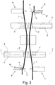
Figure 3 shows the arrangement of the clamped yarns when the tail cutting and retention step begins. Thepackage yarn 1 is clamped by theclamp 6 on the upper side and on the lower side is retained between the mobile blade 9' of thescissor 9 which partially straddles thecontrast organ 9"' imprisoning the end 1' of theyarn 1. - Similarly, the
feeding bobbing yarn 2 is clamped by theclamp 7 on the lower side and on the upper side is retained between the mobile blade 8' of thescissor 8 which partially straddles thecontrast organ 8"' imprisoning the end 2' of theyarn 2. -
Figure 4 shows the subsequent step in which thescissors blades 9" and 8" cutting the yarns just after the retention sections 1' and 2' The section of yarn 1' and 2' remain retained respectively between the mobile blades 9' and 8' and thecontrast organs 9"' and 8"'. - The sections of
yarn 1" and 2" cut by thescissors - Two tails are thus formed 1'" and 2"', comprised between the retention sections 1' and 2' and the
splicing chamber 3. -
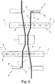
Figure 5 show the arrangement of the yarns as soon as the preparation devices are fed with the high flow rate of fluid. Thenozzles 4" and 5" of thepreparation devices - The preparation means 4,5 comprise preparation tubes 4',5' fluidically connected with
preparation nozzles 4",5", wherein thenozzles 4",5" emit jets of fluid which enter the preparation tubes 4',5'. - The tails 1'" and 2'" thus come to face the entrance of the respective tubes 4' and 5' so as to position themselves adequately for their subsequent capture by the tube 4' and 5' at the moment of release of the point 1' and 2' retained between the blades 9' and 8' and the
respective contrast organs 9"' and 8'''. - In particular, a portion of yarn comprised between the
tail 1"',2"' and thesplicing chamber 3 crosses the preparation means 4,5 in order to be directly influenced by the jets of thepreparation nozzles 4",5". - The portion of yarn crossing the preparation means 4,5 is comprised between the
preparation nozzle 4",5" and the preparation tubes 4',5', so as to being directly influenced by the flow of thepreparation nozzle 4",5" and forced to enter into said preparation tube 4',5' under the thrust of said flow, before releasing thetails 1"',2"'. - According to an embodiment, the
preparation nozzles 4",5" are aligned with aninlet port 4"',5'" of the preparation tubes 4',5', in order to directly send the jets of fluid into the preparation tubes 4',5' and directly force the yarn to enter said preparation tubes 4',5'. - According to an embodiment, the preparation tube 4',5' has a prevalent transversal direction Y-Y which is parallel to the main direction of the jets generated by said
preparation nozzles 4",5". -
Figure 6 shows the arrangement of the yarns 1'" and 2"' just after their release by the mobile blades 9' and 8' which move backwards releasing the points previously retained 1' and 2'. - The tails 1'" and 2'" are shown by a continuous line, letter a, an instant before their release, and by a dotted line, letter b, the same tails 1'" and 2"' are shown inserted in the preparation tubes 4' and 5' subject to the flow of fluid used for their preparation.
-
Figure 7 show the tails 1'" and 2'" withrespective ends 1"" and 2"" prepared by thepreparation devices splicing chamber 3 by the desired length. - Two
mobile levers yarns respective tails 1"' and 2"' return by a predetermined length towards thesplicing chamber 3. -
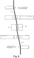
Figure 8 shows the tails 1'" and 2'" after their encompassing in thejoin 12 of theyarns splicing chamber 3, using the known method. -
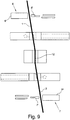
Figure 9 shows the last step, in which the mobile levers 6' and 7' free the two sections ofyarn join 12 from theblocks 6" and 7" of theclamps - The splicer is once again in the rest position and the joined yarn can be extracted to resume the winding operation.
- It is thus evident how the pneumatic splicer according to the present invention achieves the purposes highlighted above.
- In fact, the pneumatic splicer according to the present invention represents an alternative solution to the known splicers relative to the problem of controlling the freshly cut tails as the type of yarn varies.
Claims (6)
- Pneumatic splicer of the type comprising a splicing chamber (3) supplied from opposite sides with two tails (1"',2"') to be joined, for each of said tails (1"',2"') there being provided, arranged in a specular manner in relation to said splicing chamber (3), clamping means (6,7) of the tails positioned at one side of said splicing chamber (3) as well as preparation means (4,5) and cutting means (8,9) positioned on the other side of said splicing chamber (3), wherein the pneumatic splicer comprises for each tail (1"',2"'), means of selective retention and release (8',8",8"',9',9",9"') thereof positioned on the same side as said cutting means (8,9) in relation to the splicing chamber (3),
characterized in that said means of selective retention and release (8',8",8'",9',9",9"')of the tail are configured so as to co-operate with said cutting means (8,9) so as to begin to retain said tail (1"',2"') before cutting and to release it after starting the dispensing of pressurized air in the preparation tubes (4,4',5,5') of the tail (1"',2"'), wherein said cutting means (8,9) comprise a mobile blade (8',9') and a fixed blade (8",9"), said selective retention and release means of the tail comprise a contrast (8"',9"'), said blades (8',8",9',9"') and said contrast (8"',9"') being positioned in relation to each other so that said mobile blade (8',9') slides between said fixed blade (8",9") and said contrast (8"',9"') and that the retention of the tail (1'",2"') begins during the advancement of said mobile blade (8',9') before cutting and that the release begins after starting the dispensing of pressurized air in the preparation tubes (4,4',5,5') of the tail (1"',2"'),
wherein the fixed blade (8",9") is sprung and said contrast (8"',9"') is fixed in a position such as to press the yarn against the advancing mobile blade (8',9'). - Splicer according to claim 1, wherein, the preparation means (4,5) comprise preparation tubes (4',5') fluidically connected with preparation nozzles (4",5"), the nozzles (4",5") emitting jets of fluid which enter the preparation tubes (4',5'), wherein a portion of yarn comprised between the tail (1"',2"') and the splicing chamber (3) crosses the preparation means (4,5) in order to be directly influenced by the jets of the preparation nozzles (4", 5").
- Splicer according to claim 2, wherein the portion of yarn crossing the preparation means (4,5) is comprised between the preparation nozzle (4",5") and the preparation tubes (4',5'), so as to being directly influenced by the flow of the preparation nozzle (4",5") and forced to enter into said preparation tube (4',5') under the thrust of said flow, before releasing the tails (1"',2"').
- Splicer according to claim 2 or 3, wherein the preparation nozzles (4",5") are aligned with an inlet port of the preparation tubes (4',5'), in order to directly send the jets of fluid into the preparation tubes (4',5') and directly force the yarn to enter said preparation tubes (4',5').
- Splicer according to claim 2, 3 or 4, wherein the preparation tube (4',5') has a prevalent transversal direction (Y-Y) which is parallel to the main direction of the jets generated by said preparation nozzles (4",5").
- Method of joining yarn tails (1"',2"') by means of a pneumatic splicer according to claim 1, the method comprising the following manipulation steps of the tails (1"',2"') :a) intercepting and inserting said tails in a splicing chamber (3) so that they at least partially go beyond it;b) clamping said yarns on the side opposite said tails (1"',2"') in relation to the said splicing chamber (3),c) cutting the tails (1"',2"') ;d) preparing the tails (1"',2"') ;e) inserting the tails (1"',2"') in splicing chamber (3) ;f) freeing the clamps;characterized by the fact of also comprising the step of retaining said tails (1"',2"') at the cutting zone, wherein the step of preparing the tails comprises the step of dispensing pressurized air in tubes positioned between said splicing chamber (3) and said cutting zone, said step of dispensing pressurized air starting before the release of said tails (1"',2"'),
wherein said step of retaining said tails at the cutting zone starts before and terminates after cutting of the tail,
wherein said step of retaining said tails at the cutting zone is performed by elastically pressing the tails against the cutting organs.
Applications Claiming Priority (1)
| Application Number | Priority Date | Filing Date | Title |
|---|---|---|---|
| IT001748A ITMI20121748A1 (en) | 2012-10-16 | 2012-10-16 | PNEUMATIC WIRE ASSEMBLY GROUP FOR TEXTILE MACHINES |
Publications (2)
| Publication Number | Publication Date |
|---|---|
| EP2722299A1 EP2722299A1 (en) | 2014-04-23 |
| EP2722299B1 true EP2722299B1 (en) | 2017-07-05 |
Family
ID=47226279
Family Applications (1)
| Application Number | Title | Priority Date | Filing Date |
|---|---|---|---|
| EP13188559.2A Active EP2722299B1 (en) | 2012-10-16 | 2013-10-14 | Pneumatic splicer unit for textile machines |
Country Status (4)
| Country | Link |
|---|---|
| EP (1) | EP2722299B1 (en) |
| CN (2) | CN103726148B (en) |
| IN (1) | IN2013MU03232A (en) |
| IT (1) | ITMI20121748A1 (en) |
Families Citing this family (10)
| Publication number | Priority date | Publication date | Assignee | Title |
|---|---|---|---|---|
| ITMI20121748A1 (en) * | 2012-10-16 | 2014-04-17 | Savio Macchine Tessili Spa | PNEUMATIC WIRE ASSEMBLY GROUP FOR TEXTILE MACHINES |
| JP2016155648A (en) * | 2015-02-24 | 2016-09-01 | 村田機械株式会社 | Piecing unit and yarn winding device |
| CN105951224A (en) * | 2016-04-22 | 2016-09-21 | 东华大学 | Joint shearing device cooperated with gluing method and shearing method |
| CN108341083A (en) * | 2018-01-26 | 2018-07-31 | 巨石集团有限公司 | A kind of yarn knotting method of air eliminant |
| CN109295573A (en) * | 2018-11-28 | 2019-02-01 | 宜宾海丝特纤维有限责任公司 | The technique of untwisted yarn section is controlled in a kind of viscose filament yarn single twisting production process |
| CN110577114B (en) * | 2019-10-10 | 2024-03-15 | 上海枭腾纺织科技有限公司 | Full-automatic intelligent knotter |
| CN112111826A (en) * | 2020-08-27 | 2020-12-22 | 巨石集团有限公司 | Yarn knotter and yarn knotting method |
| CN114507921A (en) * | 2021-02-20 | 2022-05-17 | 王广宪 | Multi-thread layer carding device for preparing para-aramid yarns |
| CN116065273B (en) * | 2023-03-31 | 2023-05-30 | 江苏美丽华电器有限公司 | Winding tension adjusting device of false twist texturing machine |
| CN116676693A (en) * | 2023-06-14 | 2023-09-01 | 常州市宏发纵横新材料科技股份有限公司 | Fiber air twisting device and splicing method |
Family Cites Families (10)
| Publication number | Priority date | Publication date | Assignee | Title |
|---|---|---|---|---|
| JPS55106968A (en) * | 1979-02-09 | 1980-08-16 | Murata Mach Ltd | Pneumatic type thread connector |
| JPS59112038A (en) * | 1982-12-16 | 1984-06-28 | Murata Mach Ltd | Ending of spun yarn |
| JPH0791707B2 (en) * | 1987-07-21 | 1995-10-04 | 村田機械株式会社 | Yarn splicing method and device in spinning device |
| DE4008640A1 (en) * | 1990-03-17 | 1991-09-19 | Stahlecker Gmbh Wilhelm | SPLITTING DEVICE FOR CONNECTING THREADS |
| IT1299006B1 (en) * | 1998-04-02 | 2000-02-07 | Mesdan Spa | DEVICE FOR THE PREPARATION OF THE END OF THE WIRE AT THE JOINT WITH AN EQUIPMENT FOR THE PNEUMATIC JOINT WITHOUT WIRES AND |
| IT1316370B1 (en) * | 2000-02-15 | 2003-04-10 | Mesdan Spa | DEVICE AND PROCEDURE FOR JOINTING TEXTILE THREADS BY COMPRESSED AND LIQUID MEDIUM |
| DE10202781A1 (en) * | 2002-01-25 | 2003-07-31 | Schlafhorst & Co W | Device for the pneumatic connection of yarns |
| DE60216070T2 (en) * | 2002-07-24 | 2007-06-28 | Murata Kikai K.K. | A yarn splicer |
| ITMI20061977A1 (en) * | 2006-10-16 | 2008-04-17 | Mesdan Spa | METHOD FOR THE OPTIMIZED PNEUMATIC JUNCTION OF WIRES OR YARN AND ITS DEVICE |
| ITMI20121748A1 (en) * | 2012-10-16 | 2014-04-17 | Savio Macchine Tessili Spa | PNEUMATIC WIRE ASSEMBLY GROUP FOR TEXTILE MACHINES |
-
2012
- 2012-10-16 IT IT001748A patent/ITMI20121748A1/en unknown
-
2013
- 2013-10-14 EP EP13188559.2A patent/EP2722299B1/en active Active
- 2013-10-15 IN IN3232MU2013 patent/IN2013MU03232A/en unknown
- 2013-10-16 CN CN201310485399.2A patent/CN103726148B/en active Active
- 2013-10-16 CN CN201320639503.4U patent/CN203602819U/en not_active Withdrawn - After Issue
Non-Patent Citations (1)
| Title |
|---|
| None * |
Also Published As
| Publication number | Publication date |
|---|---|
| CN103726148B (en) | 2018-01-12 |
| CN103726148A (en) | 2014-04-16 |
| ITMI20121748A1 (en) | 2014-04-17 |
| EP2722299A1 (en) | 2014-04-23 |
| IN2013MU03232A (en) | 2015-07-10 |
| CN203602819U (en) | 2014-05-21 |
Similar Documents
| Publication | Publication Date | Title |
|---|---|---|
| EP2722299B1 (en) | Pneumatic splicer unit for textile machines | |
| CN101171374B (en) | Joining method on a jet spinner machine spinning device and jet spinning machine | |
| CN101165241B (en) | Method for optimizing pneumatic connecting line or yarn and corresponding equipment | |
| CH652705A5 (en) | METHOD AND DEVICE FOR SPLIT WIDNED YARNS. | |
| JP2005314104A (en) | Yarn splicing device, and handy type splicer | |
| EP2674380B1 (en) | Splicer device for splicing yarns and winding machine | |
| US6868660B2 (en) | Device and process for the pneumatic splicing of threads or yarns containing an elastomer or with a high torque | |
| CH654815A5 (en) | METHOD FOR SPLITING YARN ON A WINDING MACHINE, AND DEVICE FOR CARRYING OUT THE METHOD. | |
| JP6532489B2 (en) | Picking device and creel | |
| US20150129708A1 (en) | Rewinding machine | |
| US4433534A (en) | Apparatus for splicing spun yarns | |
| US4494368A (en) | Method of preventing irregular untwisting of yarn ends in splicing spun yarns | |
| US6854811B2 (en) | Method for producing a brush | |
| US6571545B2 (en) | Device for the pneumatic splicing of threads or yarns and a process to carry out such splicing | |
| JP2001348750A (en) | Method for dividing yarn in sectional warper and dividing apparatus | |
| US4505097A (en) | Method of splicing spun yarns | |
| CN108408490A (en) | A kind of spool yarn repiece device and method | |
| JP4339001B2 (en) | Feeding method and feeding device for weft yarn clamped in a loom to a feeding gripper | |
| US3643990A (en) | Method of and device for gripping a moving yarn end in textile machines, particularly yarn winding machines | |
| US3868133A (en) | Pneumatic yarn knotter mechanism | |
| US4587996A (en) | Weft yarn control for a weaving machine rotor | |
| US7103945B2 (en) | Machine for joining yarns | |
| CN102108576B (en) | knot aligning device | |
| JP2005230477A (en) | Sewing machine | |
| CZ2007178A3 (en) | Method of and device for introducing end of yarn into spinning nozzle of jet spinning machine |
Legal Events
| Date | Code | Title | Description |
|---|---|---|---|
| PUAI | Public reference made under article 153(3) epc to a published international application that has entered the european phase |
Free format text: ORIGINAL CODE: 0009012 |
|
| AK | Designated contracting states |
Kind code of ref document: A1 Designated state(s): AL AT BE BG CH CY CZ DE DK EE ES FI FR GB GR HR HU IE IS IT LI LT LU LV MC MK MT NL NO PL PT RO RS SE SI SK SM TR |
|
| AX | Request for extension of the european patent |
Extension state: BA ME |
|
| 17P | Request for examination filed |
Effective date: 20141021 |
|
| RBV | Designated contracting states (corrected) |
Designated state(s): AL AT BE BG CH CY CZ DE DK EE ES FI FR GB GR HR HU IE IS IT LI LT LU LV MC MK MT NL NO PL PT RO RS SE SI SK SM TR |
|
| 17Q | First examination report despatched |
Effective date: 20151113 |
|
| GRAP | Despatch of communication of intention to grant a patent |
Free format text: ORIGINAL CODE: EPIDOSNIGR1 |
|
| INTG | Intention to grant announced |
Effective date: 20170222 |
|
| GRAS | Grant fee paid |
Free format text: ORIGINAL CODE: EPIDOSNIGR3 |
|
| GRAA | (expected) grant |
Free format text: ORIGINAL CODE: 0009210 |
|
| AK | Designated contracting states |
Kind code of ref document: B1 Designated state(s): AL AT BE BG CH CY CZ DE DK EE ES FI FR GB GR HR HU IE IS IT LI LT LU LV MC MK MT NL NO PL PT RO RS SE SI SK SM TR |
|
| REG | Reference to a national code |
Ref country code: GB Ref legal event code: FG4D |
|
| REG | Reference to a national code |
Ref country code: CH Ref legal event code: EP |
|
| REG | Reference to a national code |
Ref country code: AT Ref legal event code: REF Ref document number: 906452 Country of ref document: AT Kind code of ref document: T Effective date: 20170715 |
|
| REG | Reference to a national code |
Ref country code: IE Ref legal event code: FG4D |
|
| REG | Reference to a national code |
Ref country code: DE Ref legal event code: R096 Ref document number: 602013023066 Country of ref document: DE |
|
| REG | Reference to a national code |
Ref country code: CH Ref legal event code: NV Representative=s name: MICHELI AND CIE SA, CH |
|
| REG | Reference to a national code |
Ref country code: NL Ref legal event code: MP Effective date: 20170705 |
|
| REG | Reference to a national code |
Ref country code: AT Ref legal event code: MK05 Ref document number: 906452 Country of ref document: AT Kind code of ref document: T Effective date: 20170705 |
|
| REG | Reference to a national code |
Ref country code: LT Ref legal event code: MG4D |
|
| PG25 | Lapsed in a contracting state [announced via postgrant information from national office to epo] |
Ref country code: FI Free format text: LAPSE BECAUSE OF FAILURE TO SUBMIT A TRANSLATION OF THE DESCRIPTION OR TO PAY THE FEE WITHIN THE PRESCRIBED TIME-LIMIT Effective date: 20170705 Ref country code: HR Free format text: LAPSE BECAUSE OF FAILURE TO SUBMIT A TRANSLATION OF THE DESCRIPTION OR TO PAY THE FEE WITHIN THE PRESCRIBED TIME-LIMIT Effective date: 20170705 Ref country code: AT Free format text: LAPSE BECAUSE OF FAILURE TO SUBMIT A TRANSLATION OF THE DESCRIPTION OR TO PAY THE FEE WITHIN THE PRESCRIBED TIME-LIMIT Effective date: 20170705 Ref country code: NL Free format text: LAPSE BECAUSE OF FAILURE TO SUBMIT A TRANSLATION OF THE DESCRIPTION OR TO PAY THE FEE WITHIN THE PRESCRIBED TIME-LIMIT Effective date: 20170705 Ref country code: NO Free format text: LAPSE BECAUSE OF FAILURE TO SUBMIT A TRANSLATION OF THE DESCRIPTION OR TO PAY THE FEE WITHIN THE PRESCRIBED TIME-LIMIT Effective date: 20171005 Ref country code: LT Free format text: LAPSE BECAUSE OF FAILURE TO SUBMIT A TRANSLATION OF THE DESCRIPTION OR TO PAY THE FEE WITHIN THE PRESCRIBED TIME-LIMIT Effective date: 20170705 Ref country code: SE Free format text: LAPSE BECAUSE OF FAILURE TO SUBMIT A TRANSLATION OF THE DESCRIPTION OR TO PAY THE FEE WITHIN THE PRESCRIBED TIME-LIMIT Effective date: 20170705 |
|
| PG25 | Lapsed in a contracting state [announced via postgrant information from national office to epo] |
Ref country code: IS Free format text: LAPSE BECAUSE OF FAILURE TO SUBMIT A TRANSLATION OF THE DESCRIPTION OR TO PAY THE FEE WITHIN THE PRESCRIBED TIME-LIMIT Effective date: 20171105 Ref country code: GR Free format text: LAPSE BECAUSE OF FAILURE TO SUBMIT A TRANSLATION OF THE DESCRIPTION OR TO PAY THE FEE WITHIN THE PRESCRIBED TIME-LIMIT Effective date: 20171006 Ref country code: ES Free format text: LAPSE BECAUSE OF FAILURE TO SUBMIT A TRANSLATION OF THE DESCRIPTION OR TO PAY THE FEE WITHIN THE PRESCRIBED TIME-LIMIT Effective date: 20170705 Ref country code: BG Free format text: LAPSE BECAUSE OF FAILURE TO SUBMIT A TRANSLATION OF THE DESCRIPTION OR TO PAY THE FEE WITHIN THE PRESCRIBED TIME-LIMIT Effective date: 20171005 Ref country code: RS Free format text: LAPSE BECAUSE OF FAILURE TO SUBMIT A TRANSLATION OF THE DESCRIPTION OR TO PAY THE FEE WITHIN THE PRESCRIBED TIME-LIMIT Effective date: 20170705 Ref country code: LV Free format text: LAPSE BECAUSE OF FAILURE TO SUBMIT A TRANSLATION OF THE DESCRIPTION OR TO PAY THE FEE WITHIN THE PRESCRIBED TIME-LIMIT Effective date: 20170705 Ref country code: PL Free format text: LAPSE BECAUSE OF FAILURE TO SUBMIT A TRANSLATION OF THE DESCRIPTION OR TO PAY THE FEE WITHIN THE PRESCRIBED TIME-LIMIT Effective date: 20170705 |
|
| REG | Reference to a national code |
Ref country code: DE Ref legal event code: R097 Ref document number: 602013023066 Country of ref document: DE |
|
| PG25 | Lapsed in a contracting state [announced via postgrant information from national office to epo] |
Ref country code: DK Free format text: LAPSE BECAUSE OF FAILURE TO SUBMIT A TRANSLATION OF THE DESCRIPTION OR TO PAY THE FEE WITHIN THE PRESCRIBED TIME-LIMIT Effective date: 20170705 Ref country code: RO Free format text: LAPSE BECAUSE OF FAILURE TO SUBMIT A TRANSLATION OF THE DESCRIPTION OR TO PAY THE FEE WITHIN THE PRESCRIBED TIME-LIMIT Effective date: 20170705 |
|
| PLBE | No opposition filed within time limit |
Free format text: ORIGINAL CODE: 0009261 |
|
| STAA | Information on the status of an ep patent application or granted ep patent |
Free format text: STATUS: NO OPPOSITION FILED WITHIN TIME LIMIT |
|
| PG25 | Lapsed in a contracting state [announced via postgrant information from national office to epo] |
Ref country code: SM Free format text: LAPSE BECAUSE OF FAILURE TO SUBMIT A TRANSLATION OF THE DESCRIPTION OR TO PAY THE FEE WITHIN THE PRESCRIBED TIME-LIMIT Effective date: 20170705 Ref country code: EE Free format text: LAPSE BECAUSE OF FAILURE TO SUBMIT A TRANSLATION OF THE DESCRIPTION OR TO PAY THE FEE WITHIN THE PRESCRIBED TIME-LIMIT Effective date: 20170705 Ref country code: MC Free format text: LAPSE BECAUSE OF FAILURE TO SUBMIT A TRANSLATION OF THE DESCRIPTION OR TO PAY THE FEE WITHIN THE PRESCRIBED TIME-LIMIT Effective date: 20170705 Ref country code: SK Free format text: LAPSE BECAUSE OF FAILURE TO SUBMIT A TRANSLATION OF THE DESCRIPTION OR TO PAY THE FEE WITHIN THE PRESCRIBED TIME-LIMIT Effective date: 20170705 |
|
| 26N | No opposition filed |
Effective date: 20180406 |
|
| GBPC | Gb: european patent ceased through non-payment of renewal fee |
Effective date: 20171014 |
|
| REG | Reference to a national code |
Ref country code: IE Ref legal event code: MM4A |
|
| REG | Reference to a national code |
Ref country code: FR Ref legal event code: ST Effective date: 20180629 |
|
| PG25 | Lapsed in a contracting state [announced via postgrant information from national office to epo] |
Ref country code: LU Free format text: LAPSE BECAUSE OF NON-PAYMENT OF DUE FEES Effective date: 20171014 Ref country code: GB Free format text: LAPSE BECAUSE OF NON-PAYMENT OF DUE FEES Effective date: 20171014 |
|
| REG | Reference to a national code |
Ref country code: BE Ref legal event code: MM Effective date: 20171031 |
|
| PG25 | Lapsed in a contracting state [announced via postgrant information from national office to epo] |
Ref country code: BE Free format text: LAPSE BECAUSE OF NON-PAYMENT OF DUE FEES Effective date: 20171031 Ref country code: FR Free format text: LAPSE BECAUSE OF NON-PAYMENT OF DUE FEES Effective date: 20171031 Ref country code: SI Free format text: LAPSE BECAUSE OF FAILURE TO SUBMIT A TRANSLATION OF THE DESCRIPTION OR TO PAY THE FEE WITHIN THE PRESCRIBED TIME-LIMIT Effective date: 20170705 |
|
| PG25 | Lapsed in a contracting state [announced via postgrant information from national office to epo] |
Ref country code: MT Free format text: LAPSE BECAUSE OF NON-PAYMENT OF DUE FEES Effective date: 20171014 |
|
| PG25 | Lapsed in a contracting state [announced via postgrant information from national office to epo] |
Ref country code: IE Free format text: LAPSE BECAUSE OF NON-PAYMENT OF DUE FEES Effective date: 20171014 |
|
| PG25 | Lapsed in a contracting state [announced via postgrant information from national office to epo] |
Ref country code: HU Free format text: LAPSE BECAUSE OF FAILURE TO SUBMIT A TRANSLATION OF THE DESCRIPTION OR TO PAY THE FEE WITHIN THE PRESCRIBED TIME-LIMIT; INVALID AB INITIO Effective date: 20131014 |
|
| PG25 | Lapsed in a contracting state [announced via postgrant information from national office to epo] |
Ref country code: CY Free format text: LAPSE BECAUSE OF NON-PAYMENT OF DUE FEES Effective date: 20170705 |
|
| PG25 | Lapsed in a contracting state [announced via postgrant information from national office to epo] |
Ref country code: MK Free format text: LAPSE BECAUSE OF FAILURE TO SUBMIT A TRANSLATION OF THE DESCRIPTION OR TO PAY THE FEE WITHIN THE PRESCRIBED TIME-LIMIT Effective date: 20170705 |
|
| PG25 | Lapsed in a contracting state [announced via postgrant information from national office to epo] |
Ref country code: PT Free format text: LAPSE BECAUSE OF FAILURE TO SUBMIT A TRANSLATION OF THE DESCRIPTION OR TO PAY THE FEE WITHIN THE PRESCRIBED TIME-LIMIT Effective date: 20170705 |
|
| PG25 | Lapsed in a contracting state [announced via postgrant information from national office to epo] |
Ref country code: AL Free format text: LAPSE BECAUSE OF FAILURE TO SUBMIT A TRANSLATION OF THE DESCRIPTION OR TO PAY THE FEE WITHIN THE PRESCRIBED TIME-LIMIT Effective date: 20170705 |
|
| PGFP | Annual fee paid to national office [announced via postgrant information from national office to epo] |
Ref country code: CZ Payment date: 20210826 Year of fee payment: 9 |
|
| PGFP | Annual fee paid to national office [announced via postgrant information from national office to epo] |
Ref country code: CH Payment date: 20211020 Year of fee payment: 9 |
|
| REG | Reference to a national code |
Ref country code: CH Ref legal event code: PL |
|
| P01 | Opt-out of the competence of the unified patent court (upc) registered |
Effective date: 20230526 |
|
| PG25 | Lapsed in a contracting state [announced via postgrant information from national office to epo] |
Ref country code: LI Free format text: LAPSE BECAUSE OF NON-PAYMENT OF DUE FEES Effective date: 20221031 Ref country code: CZ Free format text: LAPSE BECAUSE OF NON-PAYMENT OF DUE FEES Effective date: 20221014 Ref country code: CH Free format text: LAPSE BECAUSE OF NON-PAYMENT OF DUE FEES Effective date: 20221031 |
|
| PGFP | Annual fee paid to national office [announced via postgrant information from national office to epo] |
Ref country code: IT Payment date: 20230807 Year of fee payment: 11 |
|
| PGFP | Annual fee paid to national office [announced via postgrant information from national office to epo] |
Ref country code: TR Payment date: 20231009 Year of fee payment: 11 Ref country code: DE Payment date: 20231020 Year of fee payment: 11 |