EP2722277A1 - Direct-drive control of aircraft stability augmentation - Google Patents
Direct-drive control of aircraft stability augmentation Download PDFInfo
- Publication number
- EP2722277A1 EP2722277A1 EP13171020.4A EP13171020A EP2722277A1 EP 2722277 A1 EP2722277 A1 EP 2722277A1 EP 13171020 A EP13171020 A EP 13171020A EP 2722277 A1 EP2722277 A1 EP 2722277A1
- Authority
- EP
- European Patent Office
- Prior art keywords
- linkage
- commands
- stability augmentation
- motor
- operable
- Prior art date
- Legal status (The legal status is an assumption and is not a legal conclusion. Google has not performed a legal analysis and makes no representation as to the accuracy of the status listed.)
- Granted
Links
Images


Classifications
-
- B—PERFORMING OPERATIONS; TRANSPORTING
- B64—AIRCRAFT; AVIATION; COSMONAUTICS
- B64C—AEROPLANES; HELICOPTERS
- B64C27/00—Rotorcraft; Rotors peculiar thereto
- B64C27/54—Mechanisms for controlling blade adjustment or movement relative to rotor head, e.g. lag-lead movement
- B64C27/58—Transmitting means, e.g. interrelated with initiating means or means acting on blades
- B64C27/59—Transmitting means, e.g. interrelated with initiating means or means acting on blades mechanical
-
- B—PERFORMING OPERATIONS; TRANSPORTING
- B64—AIRCRAFT; AVIATION; COSMONAUTICS
- B64C—AEROPLANES; HELICOPTERS
- B64C27/00—Rotorcraft; Rotors peculiar thereto
- B64C27/54—Mechanisms for controlling blade adjustment or movement relative to rotor head, e.g. lag-lead movement
- B64C27/58—Transmitting means, e.g. interrelated with initiating means or means acting on blades
- B64C27/59—Transmitting means, e.g. interrelated with initiating means or means acting on blades mechanical
- B64C27/605—Transmitting means, e.g. interrelated with initiating means or means acting on blades mechanical including swash plate, spider or cam mechanisms
-
- B—PERFORMING OPERATIONS; TRANSPORTING
- B64—AIRCRAFT; AVIATION; COSMONAUTICS
- B64C—AEROPLANES; HELICOPTERS
- B64C27/00—Rotorcraft; Rotors peculiar thereto
- B64C27/001—Vibration damping devices
- B64C2027/004—Vibration damping devices using actuators, e.g. active systems
-
- Y—GENERAL TAGGING OF NEW TECHNOLOGICAL DEVELOPMENTS; GENERAL TAGGING OF CROSS-SECTIONAL TECHNOLOGIES SPANNING OVER SEVERAL SECTIONS OF THE IPC; TECHNICAL SUBJECTS COVERED BY FORMER USPC CROSS-REFERENCE ART COLLECTIONS [XRACs] AND DIGESTS
- Y10—TECHNICAL SUBJECTS COVERED BY FORMER USPC
- Y10T—TECHNICAL SUBJECTS COVERED BY FORMER US CLASSIFICATION
- Y10T74/00—Machine element or mechanism
- Y10T74/18—Mechanical movements
- Y10T74/18056—Rotary to or from reciprocating or oscillating
Definitions
- This invention relates generally to aircraft stability and control augmentation systems, and more particularly, to a direct-drive control of aircraft stability augmentation.
- a rotorcraft may include one or more rotor systems.
- a rotorcraft rotor system is a main rotor system.
- a main rotor system may generate aerodynamic lift to support the weight of the rotorcraft in flight and thrust to counteract aerodynamic drag and move the rotorcraft in forward flight.
- Another example of a rotorcraft rotor system is a tail rotor system.
- a tail rotor system may generate thrust in the same direction as the main rotor system's rotation to counter the torque effect created by the main rotor system.
- a rotor system may include one or more devices to rotate, deflect, and/or adjust rotor blades.
- a technical advantage of one embodiment may include the capability to provide stability augmentation in an aircraft.
- a technical advantage of one embodiment may also include the capability to reduce jam-type failure modes in a stability augmentation system.
- a technical advantage of one embodiment may also include the capability to reduce the weight and size of a stability augmentation system.
- a technical advantage of one embodiment may also include the capability to eliminate gearboxes from a stability augmentation system.
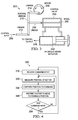
- FIGURE 1 shows a rotorcraft 100 according to one example configuration.
- Rotorcraft 100 features a rotor system 110, blades 120, a fuselage 130, a landing gear 140, and an empennage 150.
- Rotor system 110 may rotate blades 120.
- Rotor system 110 may include a control system for selectively controlling the pitch of each blade 120 in order to selectively control direction, thrust, and lift of rotorcraft 100.
- Fuselage 130 represents the body of rotorcraft 100 and may be coupled to rotor system 110 such that rotor system 110 and blades 120 may move fuselage 130 through the air.
- Landing gear 140 supports rotorcraft 100 when rotorcraft 100 is landing and/or when rotorcraft 100 is at rest on the ground.
- Empennage 150 represents the tail section of the aircraft and features components of a rotor system 110 and blades 120'. Blades 120' may provide thrust in the same direction as the rotation of blades 120 so as to counter the torque effect created by rotor system 110 and blades 120.
- Teachings of certain embodiments relating to rotor systems described herein may apply to rotor system 110 and/or other rotor systems, such as other tilt rotor and helicopter rotor systems. It should also be appreciated that teachings from rotorcraft 100 may apply to aircraft other than rotorcraft, such as airplanes and unmanned aircraft, to name a few examples.
- FIGURE 2 shows rotor system 110 and blades 120 of FIGURE 1 according to one example configuration.
- rotor system 110 features a power train 112, a hub 114, a swashplate 116, and pitch links 118.
- rotor system 110 may include more or fewer components.
- FIGURE 2 does not show components such as a gearbox, a swash plate, drive links, drive levers, and other components that may be incorporated.
- Power train 112 features a power source 112a and a drive shaft 112b.
- Power source 112a, drive shaft 112b, and hub 114 are mechanical components for transmitting torque and/or rotation.
- Power train 112 may include a variety of components, including an engine, a transmission, and differentials.
- drive shaft 112b receives torque or rotational energy from power source 112a and rotates hub 114. Rotation of rotor hub 114 causes blades 120 to rotate about drive shaft 112b.
- Swashplate 116 translates rotorcraft flight control input into motion of blades 120. Because blades 120 are typically spinning when the rotorcraft is in flight, swashplate 116 may transmit flight control input from the non-rotating fuselage to the hub 114, blades 120, and/or components coupling hub 114 to blades 120 (e.g., grips and pitch horns). References in this description to coupling between a pitch link and a hub may also include, but are not limited to, coupling between a pitch link and a blade or components coupling a hub to a blade.
- swashplate 116 may include a non-rotating swashplate ring 116a and a rotating swashplate ring 116b.
- Non-rotating swashplate ring 116a does not rotate with drive shaft 112b
- rotating swashplate ring 116b does rotate with drive shaft 112b.
- pitch links 118 connect rotating swashplate ring 116b to blades 120.
- translating the non-rotating swashplate ring 116a along the axis of drive shaft 112b causes the pitch links 118 to move up or down. This changes the pitch angle of all blades 120 equally, increasing or decreasing the thrust of the rotor and causing the aircraft to ascend or descend. Tilting the non-rotating swashplate ring 116a causes the rotating swashplate 116b to tilt, moving the pitch links 118 up and down cyclically as they rotate with the drive shaft. This tilts the thrust vector of the rotor, causing rotorcraft 100 to translate horizontally following the direction the swashplate is tilted.
- a stability augmentation system may be provided to the stabilize the movement of flight-control devices such as swashplate 116.
- flight-control devices such as swashplate 116.
- a stability augmentation system may add damping to a flight-control system to increase stability.
- FIGURE 3 shows a stability augmentation system 200 according to one example embodiment.
- System 200 features a master linkage 210; linkages 212, 214, and 216; a stability augmentation motor 220; a control valve 230; and a hydraulic actuator 240.
- teachings of certain embodiments also recognize that system 200 may include more, fewer, or different components.
- FIGURE 3 does not show components that may mechanically and/or hydraulically link the swashplate 116 of FIGURE 2 to the hydraulic actuator 240 of FIGURE 3 .
- Master linkage 210 and linkages 212, 214, and 216 may be constructed from any suitable material.
- master linkage 210 and linkages 212, 214, and 216 may be considered rigid, and the connections between the linkages may be considered joints.
- the joint between master linkage 210 and linkage 214 may operate as an adjustable fulcrum.
- control input 205 may cause the joint between master linkage 210 and linkage 212 to rotate about the joint between master linkage 210 and linkage 212.
- the joint between master linkage 210 and linkage 216 may move in response to this rotation, causing linkage 216 to move.
- the position of the joint between master linkage 210 and linkage 214 is adjustable by motor 220.
- motor 220 may reposition linkage 214 such that the joint between master linkage 210 and linkage 214 moves to a different position.
- Stability augmentation motor 220 moves linkage 214.
- stability augmentation motor 220 may be a torque motor.
- stability augmentation motor 220 may provide a substantially constant torque over a limited range.
- motor 220 is shown as a rotary motor, but embodiments of system 200 may also include a linear motor.
- system 200 may include two or more stability augmentation motors 220.
- a fourth linkage may couple a second motor to master linkage 210 proximate to the joint between master linkage 210 and linkage 214.
- the torque provided by two or more motors may be mechanically summed at master linkage 210.
- Control valve 230 and hydraulic actuator 240 may convert movements of linkage 216 into a control output 245.
- control valve 230 includes a spool 235 that is coupled to linkage 216. Moving spool 235 may open and close passages within control valve 230 which, in turn, may change the hydraulic pressures within hydraulic actuator 240.
- a change in hydraulic output pressure by hydraulic actuator 240 may represent one example of a control output 245.
- the control output 245 may move an aircraft control device (e.g., swashplate 116).
- control output 245 may represent a change in hydraulic pressure by hydraulic actuator 240, which may cause swashplate 116 to change position.
- stability augmentation motor 220 repositions linkage 214 to provide stability augmentation to system 200.
- the aircraft control device associated with control output 245 may tend toward low damping or even instability.
- low damping or instability may cause hydraulic actuator 240 to oscillate or vibrate, which may result in spool 235 and linkage 216 oscillating or vibrating as well.
- oscillations and vibrations in linkage 216 could cause linkage 212 to oscillate and vibrate.
- oscillations and vibrations in linkage 212 could cause the pilot control stick to oscillate and vibrate.
- Motor 220 may reduce or even eliminate pilot control stick oscillations and vibrations by moving linkage 214 to counteract oscillations and vibrations in linkage 216.
- linkage 216 moves master linkage 210
- motor 220 could move linkage 214 in such a manner so as to keep the joint between master linkage 210 and linkage 212 in approximately the same position.
- motor 220 and linkage 214 may provide stability augmentation to system 200 by counteracting the oscillations and vibrations in linkage 216.
- master linkage 210 may act as a "summing" linkage by mechanically summing inputs from linkage 212 and linkages 214 and providing the summed mechanical output to linkage 216.
- linkage 212 may provide a mechanical input to linkage 216 through master linkage 210, but linkage 214 may be moved so as to add to or subtract from this mechanical input. If the mechanical input from linkage 212 would result in linkage 216 moving a certain distance in a certain direction, for example, moving linkage 214 may change the distance that linkage 216 moves and/or change the direction in which linkage 216 moves.
- linkage 216 may oscillate or vibrate at a high frequency.
- motor 220 may oscillate linkage 214 at a sufficiently high frequency so as to counteract the oscillations of linkage 216.
- a limited-angle torque motor may provide torque with sufficient control, precision, and bandwidth so as to counteract the oscillations of linkage 216.
- motor 220 may provide sufficient torque without the use of gearboxes and other devices designed to multiple the torque output. Such gearboxes may add complexity and weight and may limit the ability of motor 220 to control the position of linkage 214.
- system 200 may continue to operate even if motor 220 fails.
- the pilot may continue to control the aircraft even if motor 220 fails. If motor 220 stops operating, for example, linkage 214 may become fixed by motor 220 while still allowing master linkage 210 and linkages 212 and 216 to move. In this example, the pilot control stick may oscillate and vibrate, but the pilot would still have the ability to control the aircraft control devices.
- the aircraft control device in communication with hydraulic actuator 240 is a rotor flight control device such as swashplate 116.
- system 200 may operate with a variety of flight control devices on a variety of aircraft.
- system 200 may provide stability augmentation for aileron, flap, and/or rudder controls on an airplane.
- motor 220 may be controlled and/or monitored by a flight control computer.
- a flight control computer may instruct motor 220 on how to move linkage 214 so as to counteract the oscillations of linkage 216.
- FIGURE 4 shows a method 300 of controlling and monitoring motor 220 according to one example embodiment.
- a command input is received.
- this command input may be provided by a flight control computer.
- the command input may specify, for example, an output position of motor 220, which is mechanically related to the position of linkage 214.
- the current position of motor 220 is measured.
- the current position of motor 220 is compared with the command input position.
- motor 220 is instructed to move its output position to the command position.
- motor 220 may be subject to various vibrations and other movements. Accordingly, teachings of certain embodiments recognize the capability to periodically remeasure the output position of motor 220 and adjust the output position if it does not match the command position. Accordingly, after step 340, method 300 may return to step 320 even if no new command input is received. If a new command input specifying a new command position is received, then method 300 may return to step 310.
Landscapes
- Engineering & Computer Science (AREA)
- Mechanical Engineering (AREA)
- Aviation & Aerospace Engineering (AREA)
- Feedback Control In General (AREA)
- Transmission Devices (AREA)
- Toys (AREA)
Abstract
Description
- This invention relates generally to aircraft stability and control augmentation systems, and more particularly, to a direct-drive control of aircraft stability augmentation.
- A rotorcraft may include one or more rotor systems. One example of a rotorcraft rotor system is a main rotor system. A main rotor system may generate aerodynamic lift to support the weight of the rotorcraft in flight and thrust to counteract aerodynamic drag and move the rotorcraft in forward flight. Another example of a rotorcraft rotor system is a tail rotor system. A tail rotor system may generate thrust in the same direction as the main rotor system's rotation to counter the torque effect created by the main rotor system. A rotor system may include one or more devices to rotate, deflect, and/or adjust rotor blades.
- Particular embodiments of the present disclosure may provide one or more technical advantages. A technical advantage of one embodiment may include the capability to provide stability augmentation in an aircraft. A technical advantage of one embodiment may also include the capability to reduce jam-type failure modes in a stability augmentation system. A technical advantage of one embodiment may also include the capability to reduce the weight and size of a stability augmentation system. A technical advantage of one embodiment may also include the capability to eliminate gearboxes from a stability augmentation system.
- Certain embodiments of the present disclosure may include some, all, or none of the above advantages. One or more other technical advantages may be readily apparent to those skilled in the art from the figures, descriptions, and claims included herein.
- To provide a more complete understanding of the present invention and the features and advantages thereof, reference is made to the following description taken in conjunction with the accompanying drawings, in which:
-
Figure 1 shows a rotorcraft according to one example configuration; -
Figure 2 shows the rotor system and blades ofFIGURE 1 according to one example configuration; -
Figure 3 shows a stability augmentation system according to one example embodiment; and -
Figure 4 shows a method of controlling and monitoring the motor ofFIGURE 3 according to one example embodiment. -
FIGURE 1 shows arotorcraft 100 according to one example configuration. Rotorcraft 100 features arotor system 110,blades 120, afuselage 130, alanding gear 140, and anempennage 150.Rotor system 110 may rotateblades 120.Rotor system 110 may include a control system for selectively controlling the pitch of eachblade 120 in order to selectively control direction, thrust, and lift ofrotorcraft 100.Fuselage 130 represents the body ofrotorcraft 100 and may be coupled torotor system 110 such thatrotor system 110 andblades 120 may movefuselage 130 through the air.Landing gear 140 supportsrotorcraft 100 when rotorcraft 100 is landing and/or when rotorcraft 100 is at rest on the ground.Empennage 150 represents the tail section of the aircraft and features components of arotor system 110 and blades 120'. Blades 120' may provide thrust in the same direction as the rotation ofblades 120 so as to counter the torque effect created byrotor system 110 andblades 120. Teachings of certain embodiments relating to rotor systems described herein may apply torotor system 110 and/or other rotor systems, such as other tilt rotor and helicopter rotor systems. It should also be appreciated that teachings fromrotorcraft 100 may apply to aircraft other than rotorcraft, such as airplanes and unmanned aircraft, to name a few examples. -
FIGURE 2 showsrotor system 110 andblades 120 ofFIGURE 1 according to one example configuration. In the example configuration ofFIGURE 2 ,rotor system 110 features a power train 112, ahub 114, aswashplate 116, andpitch links 118. In some examples,rotor system 110 may include more or fewer components. For example,FIGURE 2 does not show components such as a gearbox, a swash plate, drive links, drive levers, and other components that may be incorporated. - Power train 112 features a
power source 112a and a drive shaft112b. Power source 112a,drive shaft 112b, andhub 114 are mechanical components for transmitting torque and/or rotation. Power train 112 may include a variety of components, including an engine, a transmission, and differentials. In operation,drive shaft 112b receives torque or rotational energy frompower source 112a and rotateshub 114. Rotation ofrotor hub 114 causesblades 120 to rotate aboutdrive shaft 112b. - Swashplate 116 translates rotorcraft flight control input into motion of
blades 120. Becauseblades 120 are typically spinning when the rotorcraft is in flight,swashplate 116 may transmit flight control input from the non-rotating fuselage to thehub 114,blades 120, and/orcomponents coupling hub 114 to blades 120 (e.g., grips and pitch horns). References in this description to coupling between a pitch link and a hub may also include, but are not limited to, coupling between a pitch link and a blade or components coupling a hub to a blade. - In some examples,
swashplate 116 may include anon-rotating swashplate ring 116a and a rotatingswashplate ring 116b. Non-rotatingswashplate ring 116a does not rotate withdrive shaft 112b, whereas rotatingswashplate ring 116b does rotate withdrive shaft 112b. In the example ofFIGURE 2 ,pitch links 118 connect rotatingswashplate ring 116b toblades 120. - In operation, according to one example embodiment, translating the
non-rotating swashplate ring 116a along the axis ofdrive shaft 112b causes thepitch links 118 to move up or down. This changes the pitch angle of allblades 120 equally, increasing or decreasing the thrust of the rotor and causing the aircraft to ascend or descend. Tilting thenon-rotating swashplate ring 116a causes the rotatingswashplate 116b to tilt, moving thepitch links 118 up and down cyclically as they rotate with the drive shaft. This tilts the thrust vector of the rotor, causingrotorcraft 100 to translate horizontally following the direction the swashplate is tilted. - In some examples, a stability augmentation system may be provided to the stabilize the movement of flight-control devices such as
swashplate 116. In general, the inherent stability and response behavior of many modern aircraft flight-control systems may tend towards low damping or even instability. A stability augmentation system may add damping to a flight-control system to increase stability. -
FIGURE 3 shows astability augmentation system 200 according to one example embodiment.System 200 features amaster linkage 210;linkages stability augmentation motor 220; acontrol valve 230; and ahydraulic actuator 240. Teachings of certain embodiments also recognize thatsystem 200 may include more, fewer, or different components. As one example,FIGURE 3 does not show components that may mechanically and/or hydraulically link theswashplate 116 ofFIGURE 2 to thehydraulic actuator 240 ofFIGURE 3 . -
Master linkage 210 andlinkages master linkage 210 andlinkages - In the example of
FIGURE 3 , the joint betweenmaster linkage 210 andlinkage 214 may operate as an adjustable fulcrum. In this manner,control input 205 may cause the joint betweenmaster linkage 210 andlinkage 212 to rotate about the joint betweenmaster linkage 210 andlinkage 212. The joint betweenmaster linkage 210 andlinkage 216 may move in response to this rotation, causinglinkage 216 to move. The position of the joint betweenmaster linkage 210 andlinkage 214 is adjustable bymotor 220. For example,motor 220 may repositionlinkage 214 such that the joint betweenmaster linkage 210 andlinkage 214 moves to a different position. -
Stability augmentation motor 220 moveslinkage 214. In some embodiments,stability augmentation motor 220 may be a torque motor. In some embodiments,stability augmentation motor 220 may provide a substantially constant torque over a limited range. In the example ofFIGURE 3 ,motor 220 is shown as a rotary motor, but embodiments ofsystem 200 may also include a linear motor. In some embodiments,system 200 may include two or morestability augmentation motors 220. For example, a fourth linkage may couple a second motor tomaster linkage 210 proximate to the joint betweenmaster linkage 210 andlinkage 214. In this and other examples, the torque provided by two or more motors may be mechanically summed atmaster linkage 210. -
Control valve 230 andhydraulic actuator 240, in combination, may convert movements oflinkage 216 into acontrol output 245. In the example ofFIGURE 3 ,control valve 230 includes aspool 235 that is coupled tolinkage 216. Movingspool 235 may open and close passages withincontrol valve 230 which, in turn, may change the hydraulic pressures withinhydraulic actuator 240. A change in hydraulic output pressure byhydraulic actuator 240 may represent one example of acontrol output 245. Thecontrol output 245 may move an aircraft control device (e.g., swashplate 116). For example,control output 245 may represent a change in hydraulic pressure byhydraulic actuator 240, which may causeswashplate 116 to change position. - In operation, according to one example embodiment,
stability augmentation motor 220 repositionslinkage 214 to provide stability augmentation tosystem 200. For example, the aircraft control device associated withcontrol output 245 may tend toward low damping or even instability. In this example, low damping or instability may causehydraulic actuator 240 to oscillate or vibrate, which may result inspool 235 andlinkage 216 oscillating or vibrating as well. Withoutmotor 220 andlinkage 214, oscillations and vibrations inlinkage 216 could causelinkage 212 to oscillate and vibrate. In a mechanical flight control system, oscillations and vibrations inlinkage 212 could cause the pilot control stick to oscillate and vibrate.Motor 220, however, may reduce or even eliminate pilot control stick oscillations and vibrations by movinglinkage 214 to counteract oscillations and vibrations inlinkage 216. For example, iflinkage 216 movesmaster linkage 210,motor 220 could movelinkage 214 in such a manner so as to keep the joint betweenmaster linkage 210 andlinkage 212 in approximately the same position. Thus in this example,motor 220 andlinkage 214 may provide stability augmentation tosystem 200 by counteracting the oscillations and vibrations inlinkage 216. - Teachings of certain embodiments recognize that
master linkage 210 may act as a "summing" linkage by mechanically summing inputs fromlinkage 212 andlinkages 214 and providing the summed mechanical output tolinkage 216. For example,linkage 212 may provide a mechanical input tolinkage 216 throughmaster linkage 210, butlinkage 214 may be moved so as to add to or subtract from this mechanical input. If the mechanical input fromlinkage 212 would result inlinkage 216 moving a certain distance in a certain direction, for example, movinglinkage 214 may change the distance thatlinkage 216 moves and/or change the direction in whichlinkage 216 moves. - In some circumstances,
linkage 216 may oscillate or vibrate at a high frequency. In this example, teachings of certain embodiments recognize thatmotor 220 may oscillatelinkage 214 at a sufficiently high frequency so as to counteract the oscillations oflinkage 216. Teachings of certain embodiments recognize that a limited-angle torque motor may provide torque with sufficient control, precision, and bandwidth so as to counteract the oscillations oflinkage 216. Teachings of certain embodiments recognize thatmotor 220 may provide sufficient torque without the use of gearboxes and other devices designed to multiple the torque output. Such gearboxes may add complexity and weight and may limit the ability ofmotor 220 to control the position oflinkage 214. - Teachings of certain embodiments recognize that
system 200 may continue to operate even ifmotor 220 fails. In particular, the pilot may continue to control the aircraft even ifmotor 220 fails. Ifmotor 220 stops operating, for example,linkage 214 may become fixed bymotor 220 while still allowingmaster linkage 210 andlinkages - In the example of
FIGURES 1-3 , the aircraft control device in communication withhydraulic actuator 240 is a rotor flight control device such asswashplate 116. Teachings of certain embodiments recognize, however, thatsystem 200 may operate with a variety of flight control devices on a variety of aircraft. As one non-limiting example,system 200 may provide stability augmentation for aileron, flap, and/or rudder controls on an airplane. - In some embodiments,
motor 220 may be controlled and/or monitored by a flight control computer. For example, a flight control computer may instructmotor 220 on how to movelinkage 214 so as to counteract the oscillations oflinkage 216.FIGURE 4 shows amethod 300 of controlling andmonitoring motor 220 according to one example embodiment. Atstep 310, a command input is received. In one example, this command input may be provided by a flight control computer. The command input may specify, for example, an output position ofmotor 220, which is mechanically related to the position oflinkage 214. Atstep 320, the current position ofmotor 220 is measured. Atstep 330, the current position ofmotor 220 is compared with the command input position. Atstep 340,motor 220 is instructed to move its output position to the command position. - During operation,
motor 220 may be subject to various vibrations and other movements. Accordingly, teachings of certain embodiments recognize the capability to periodically remeasure the output position ofmotor 220 and adjust the output position if it does not match the command position. Accordingly, afterstep 340,method 300 may return to step 320 even if no new command input is received. If a new command input specifying a new command position is received, thenmethod 300 may return to step 310. - Modifications, additions, or omissions may be made to the systems and apparatuses described herein without departing from the scope of the invention. The components of the systems and apparatuses may be integrated or separated. Moreover, the operations of the systems and apparatuses may be performed by more, fewer, or other components. The methods may include more, fewer, or other steps. Additionally, steps may be performed in any suitable order.
- Although several embodiments have been illustrated and described in detail, it will be recognized that substitutions and alterations are possible without departing from the spirit and scope of the present invention, as defined by the appended claims.
- To aid the Patent Office, and any readers of any patent issued on this application in interpreting the claims appended hereto, applicants wish to note that they do not intend any of the appended claims to invoke paragraph 6 of 35 U.S.C. § 112 as it exists on the date of filing hereof unless the words "means for" or "step for" are explicitly used in the particular claim.
Claims (15)
- A rotorcraft, comprising:a body;a power train coupled to the body and comprising a power source and a drive shaft coupled to the power source;a hub coupled to the drive shaft;a rotor blade coupled to the hub;a blade control system operable to change a position of the rotor blade; anda stability augmentation system coupled between the blade control system and a pilot command system, the control augmentation system comprising:a master linkage;a first linkage coupled between the master linkage and the pilot command system and operable to receive movements representative of pilot commands from the pilot command system;a stability augmentation motor;a second linkage coupled between the stability augmentation motor and the master linkage and operable to receive movements representative of augmentation commands from the stability augmentation motor; anda third linkage coupled between the blade control system and the master linkage and operable to transmit movements representative of blade position commands to the blade control system in response to the movements representative of pilot commands and the movements representative of augmentation commands.
- The rotorcraft of Claim 1, wherein the second linkage is coupled to the master linkage between the first linkage and the third linkage.
- The rotorcraft of Claim 1 or Claim 2, wherein the third linkage is operable to transmit the movements representative of blade position commands to the blade control system as a mechanical sum of the movements representative of the pilot commands and the movements representative of the augmentation commands.
- The rotorcraft of Claim 1 or Claim 2 or Claim 3, wherein the stability augmentation motor is a rotary motor or a linear motor, and optionally or preferably wherein the stability augmentation motor is a rotary torque motor operable to provide a constant torque over a limited range of motion.
- The rotorcraft of Claim 1 or any of Claims 2 to 4, wherein the second linkage is coupled to the stability augmentation motor at a first end and to the master linkage at a second end opposite the first end.
- The rotorcraft of Claim 1 or any of Claims 2 to 5, wherein the second linkage is operable to transmit torque from the stability augmentation motor to the master linkage without multiplying the torque received from the stability augmentation motor.
- The rotorcraft of Claim 1 or any of Claims 2 to 6, wherein the blade control system comprises a hydraulic control valve, wherein the third linkage is coupled to a spool associated with the hydraulic control valve.
- The rotorcraft of Claim 7, wherein the blade control system further comprises a hydraulic actuator in fluid communication with the control valve, wherein movement of the spool by the third linkage is operable to change a hydraulic pressure within the hydraulic actuator.
- The rotorcraft of Claim 1 or of any preceding Claim, further comprising:a second stability augmentation motor; anda fourth linkage coupled between the second stability augmentation motor and the master linkage and operable to receive augmentation commands from the second stability augmentation motor, and optionally or preferably wherein the second and fourth linkages are coupled to the master linkage at an approximately common location.
- A method of providing stability augmentation in an aircraft, comprising:receiving mechanical movements representative of pilot commands;receiving mechanical movements representative of stability augmentation commands;mechanically summing the mechanical movements representative of pilot commands and the mechanical movements representative of stability augmentation commands to yield mechanical movements representative of position commands; andtransmitting the mechanical movements representative of position commands to a control system.
- The method of Claim 10, wherein the position commands are blade position commands, and the control system is a blade control system operable to change a position of a rotor blade.
- The method of Claim 10, wherein the position commands are flight control surface commands, and the control system is operable to change a position of a flight control surface.
- A stability augmentation system comprising:a master linkage;a first linkage coupled to the master linkage and operable to receive movements representative of pilot commands;a stability augmentation motor;a second linkage coupled between the stability augmentation motor and the master linkage and operable to receive movements representative of augmentation commands from the stability augmentation motor; anda third linkage coupled to the master linkage and operable to transmit movements representative of blade position commands to a blade control system in response to the movements representative of pilot commands and the movements representative of augmentation commands.
- The stability augmentation system of Claim 13, wherein the second linkage is coupled to the master linkage between the first linkage and the third linkage; and/or
the stability augmentation system of Claim 13, wherein the third linkage is operable to transmit the movements representative of blade position commands to the blade control system as a mechanical sum of the movements representative of the pilot commands and the movements representative of the augmentation commands. - The stability augmentation system of Claim 13 or Claim 14, wherein the second linkage is operable to transmit torque from the stability augmentation motor to the master linkage without multiplying the torque received from the stability augmentation motor; and/or
wherein the stability augmentation system further comprises:a second stability augmentation motor; anda fourth linkage coupled between the second stability augmentation motor and the master linkage and operable to receive augmentation commands from the second stability augmentation motor.
Applications Claiming Priority (1)
| Application Number | Priority Date | Filing Date | Title |
|---|---|---|---|
| US13/655,778 US8967552B2 (en) | 2012-10-19 | 2012-10-19 | Direct-drive control of aircraft stability augmentation |
Publications (2)
| Publication Number | Publication Date |
|---|---|
| EP2722277A1 true EP2722277A1 (en) | 2014-04-23 |
| EP2722277B1 EP2722277B1 (en) | 2015-03-11 |
Family
ID=48613446
Family Applications (1)
| Application Number | Title | Priority Date | Filing Date |
|---|---|---|---|
| EP13171020.4A Active EP2722277B1 (en) | 2012-10-19 | 2013-06-07 | Direct-drive control of aircraft stability augmentation |
Country Status (4)
| Country | Link |
|---|---|
| US (1) | US8967552B2 (en) |
| EP (1) | EP2722277B1 (en) |
| CN (1) | CN103770941B (en) |
| CA (1) | CA2829734C (en) |
Cited By (1)
| Publication number | Priority date | Publication date | Assignee | Title |
|---|---|---|---|---|
| EP3868654A1 (en) * | 2020-02-19 | 2021-08-25 | Microtecnica S.r.l. | Servo-actuator architecture with electromechanical-stability and control augmentation system |
Families Citing this family (6)
| Publication number | Priority date | Publication date | Assignee | Title |
|---|---|---|---|---|
| US10618645B2 (en) | 2015-08-25 | 2020-04-14 | Aerovironment, Inc. | Ganged servo flight control system for an unmanned aerial vehicle |
| CN106828884A (en) * | 2015-12-04 | 2017-06-13 | 中航通飞研究院有限公司 | The method that amphibious aircraft flight control system installs control augmentation stability system additional |
| US10507910B2 (en) * | 2017-02-24 | 2019-12-17 | The Boeing Company | Dual-input mechanical bypass linkage apparatus and methods |
| EP3598263A1 (en) * | 2017-10-05 | 2020-01-22 | LEONARDO S.p.A. | Stability and command augmentation system for an aircraft |
| EP4019823A1 (en) | 2018-03-23 | 2022-06-29 | SZ DJI Technology Co., Ltd. | Load-stabilizing apparatus |
| WO2019178878A1 (en) * | 2018-03-23 | 2019-09-26 | 深圳市大疆创新科技有限公司 | Vertical stability enhancing mechanism and vertical stability enhancing device |
Citations (5)
| Publication number | Priority date | Publication date | Assignee | Title |
|---|---|---|---|---|
| GB2065042A (en) * | 1979-12-13 | 1981-06-24 | Sperry Corp | Multifunction servoactuator apparatus for aircraft |
| EP1037130A2 (en) * | 1999-03-12 | 2000-09-20 | Advanced Technology Institute of Commuter-Helicopter, Ltd. | Flight control apparatus for helicopters |
| US20050173595A1 (en) * | 2004-02-05 | 2005-08-11 | Hoh Roger H. | Helicopter force-feel and stability augmentation system with parallel servo-actuator |
| US20090266940A1 (en) * | 2008-04-25 | 2009-10-29 | David George Miller | Precision adjust split detent for a vehicle |
| US20110031346A1 (en) * | 2009-06-16 | 2011-02-10 | Eurocopter | Method of assisting piloting, piloting assistance means, and a piloting assistance device for a rotorcraft using said piloting assistance means to implement said piloting assistance method |
Family Cites Families (4)
| Publication number | Priority date | Publication date | Assignee | Title |
|---|---|---|---|---|
| US3021097A (en) * | 1956-06-28 | 1962-02-13 | Sperry Rand Corp | Automatic pilot for dirigible craft |
| US3050276A (en) * | 1958-09-02 | 1962-08-21 | United Aircraft Corp | Automatic stabilization device |
| US4095763A (en) * | 1977-02-25 | 1978-06-20 | Textron, Inc. | Fail safe augmentation system |
| US5058825A (en) * | 1989-02-09 | 1991-10-22 | Denis Rabouyt | Steering aid for rotor aircraft |
-
2012
- 2012-10-19 US US13/655,778 patent/US8967552B2/en active Active
-
2013
- 2013-06-07 EP EP13171020.4A patent/EP2722277B1/en active Active
- 2013-10-08 CA CA2829734A patent/CA2829734C/en active Active
- 2013-10-21 CN CN201310495665.XA patent/CN103770941B/en not_active Expired - Fee Related
Patent Citations (5)
| Publication number | Priority date | Publication date | Assignee | Title |
|---|---|---|---|---|
| GB2065042A (en) * | 1979-12-13 | 1981-06-24 | Sperry Corp | Multifunction servoactuator apparatus for aircraft |
| EP1037130A2 (en) * | 1999-03-12 | 2000-09-20 | Advanced Technology Institute of Commuter-Helicopter, Ltd. | Flight control apparatus for helicopters |
| US20050173595A1 (en) * | 2004-02-05 | 2005-08-11 | Hoh Roger H. | Helicopter force-feel and stability augmentation system with parallel servo-actuator |
| US20090266940A1 (en) * | 2008-04-25 | 2009-10-29 | David George Miller | Precision adjust split detent for a vehicle |
| US20110031346A1 (en) * | 2009-06-16 | 2011-02-10 | Eurocopter | Method of assisting piloting, piloting assistance means, and a piloting assistance device for a rotorcraft using said piloting assistance means to implement said piloting assistance method |
Cited By (2)
| Publication number | Priority date | Publication date | Assignee | Title |
|---|---|---|---|---|
| EP3868654A1 (en) * | 2020-02-19 | 2021-08-25 | Microtecnica S.r.l. | Servo-actuator architecture with electromechanical-stability and control augmentation system |
| US11584511B2 (en) | 2020-02-19 | 2023-02-21 | Microtecnica S.R.L. | Servo-actuator architecture with electromechanical-stability and control augmentation system |
Also Published As
| Publication number | Publication date |
|---|---|
| CN103770941A (en) | 2014-05-07 |
| US8967552B2 (en) | 2015-03-03 |
| EP2722277B1 (en) | 2015-03-11 |
| US20140110532A1 (en) | 2014-04-24 |
| CA2829734A1 (en) | 2014-04-19 |
| CN103770941B (en) | 2016-04-27 |
| CA2829734C (en) | 2016-02-09 |
Similar Documents
| Publication | Publication Date | Title |
|---|---|---|
| CA2829734C (en) | Direct-drive control of aircraft stability augmentation | |
| EP2076436B1 (en) | Dual higher harmonic control (hhc) for a counter-rotating, coaxial rotor system | |
| US9181811B2 (en) | Device for varying lade pitch of a lift rotor | |
| EP2678221B1 (en) | Blade-pitch control system with feedback swashplate | |
| EP2604513B1 (en) | Blade-pitch control system with feedback lever | |
| EP2796368B1 (en) | Integration of rotary electrical actuator for swashplateless individual blade control | |
| EP3431392B1 (en) | Higher harmonic control augmented with active vibration control | |
| EA021156B1 (en) | HELICOPTER WITH OPTIMAL ROTATING SCREWS WITHOUT A CYCLIC CHANGE OF STEP, EQUIPPED WITH MEANS OF AERODYNAMIC CONTROL OF THE POSITION AND FLIGHT TRAJECTORY | |
| EP3450308A1 (en) | Adaptable rotor control system for a variable number of blades | |
| US20150001337A1 (en) | Independent Hydraulic Control System for Rotorcraft Secondary Rotor | |
| US9139298B2 (en) | Rotorcraft control system for rotorcraft with two or more rotor systems | |
| EP3168145B1 (en) | Reduced power individual blade control system on a rotorcraft | |
| EP3446973A1 (en) | Adaptable rotor control system for a variable number of blades | |
| EP2907747A1 (en) | Cyclic pitch actuation system for counter-rotating propellers | |
| US20160200430A1 (en) | Tail Rotor Actuation System | |
| WO2016057215A1 (en) | Anti-vibration moment generating aircraft actuation system | |
| JP7200410B2 (en) | periodic pitch angle adjuster | |
| EP3421360A1 (en) | Independent propeller/main rotor speed control for x2 technology | |
| US10752349B2 (en) | Active counterweight for main rotor |
Legal Events
| Date | Code | Title | Description |
|---|---|---|---|
| PUAI | Public reference made under article 153(3) epc to a published international application that has entered the european phase |
Free format text: ORIGINAL CODE: 0009012 |
|
| 17P | Request for examination filed |
Effective date: 20130607 |
|
| AK | Designated contracting states |
Kind code of ref document: A1 Designated state(s): AL AT BE BG CH CY CZ DE DK EE ES FI FR GB GR HR HU IE IS IT LI LT LU LV MC MK MT NL NO PL PT RO RS SE SI SK SM TR |
|
| AX | Request for extension of the european patent |
Extension state: BA ME |
|
| GRAP | Despatch of communication of intention to grant a patent |
Free format text: ORIGINAL CODE: EPIDOSNIGR1 |
|
| RIC1 | Information provided on ipc code assigned before grant |
Ipc: B64C 27/56 20060101AFI20140905BHEP Ipc: B64C 27/59 20060101ALI20140905BHEP Ipc: B64C 27/00 20060101ALI20140905BHEP Ipc: B64C 27/605 20060101ALI20140905BHEP |
|
| INTG | Intention to grant announced |
Effective date: 20140930 |
|
| GRAS | Grant fee paid |
Free format text: ORIGINAL CODE: EPIDOSNIGR3 |
|
| GRAA | (expected) grant |
Free format text: ORIGINAL CODE: 0009210 |
|
| AK | Designated contracting states |
Kind code of ref document: B1 Designated state(s): AL AT BE BG CH CY CZ DE DK EE ES FI FR GB GR HR HU IE IS IT LI LT LU LV MC MK MT NL NO PL PT RO RS SE SI SK SM TR |
|
| REG | Reference to a national code |
Ref country code: GB Ref legal event code: FG4D |
|
| REG | Reference to a national code |
Ref country code: CH Ref legal event code: EP |
|
| REG | Reference to a national code |
Ref country code: IE Ref legal event code: FG4D |
|
| REG | Reference to a national code |
Ref country code: AT Ref legal event code: REF Ref document number: 715158 Country of ref document: AT Kind code of ref document: T Effective date: 20150415 |
|
| REG | Reference to a national code |
Ref country code: DE Ref legal event code: R096 Ref document number: 602013001158 Country of ref document: DE Effective date: 20150423 |
|
| REG | Reference to a national code |
Ref country code: NL Ref legal event code: VDEP Effective date: 20150311 |
|
| REG | Reference to a national code |
Ref country code: NL Ref legal event code: VDEP Effective date: 20150311 |
|
| PG25 | Lapsed in a contracting state [announced via postgrant information from national office to epo] |
Ref country code: LT Free format text: LAPSE BECAUSE OF FAILURE TO SUBMIT A TRANSLATION OF THE DESCRIPTION OR TO PAY THE FEE WITHIN THE PRESCRIBED TIME-LIMIT Effective date: 20150311 Ref country code: ES Free format text: LAPSE BECAUSE OF FAILURE TO SUBMIT A TRANSLATION OF THE DESCRIPTION OR TO PAY THE FEE WITHIN THE PRESCRIBED TIME-LIMIT Effective date: 20150311 Ref country code: FI Free format text: LAPSE BECAUSE OF FAILURE TO SUBMIT A TRANSLATION OF THE DESCRIPTION OR TO PAY THE FEE WITHIN THE PRESCRIBED TIME-LIMIT Effective date: 20150311 Ref country code: SE Free format text: LAPSE BECAUSE OF FAILURE TO SUBMIT A TRANSLATION OF THE DESCRIPTION OR TO PAY THE FEE WITHIN THE PRESCRIBED TIME-LIMIT Effective date: 20150311 Ref country code: NO Free format text: LAPSE BECAUSE OF FAILURE TO SUBMIT A TRANSLATION OF THE DESCRIPTION OR TO PAY THE FEE WITHIN THE PRESCRIBED TIME-LIMIT Effective date: 20150611 Ref country code: HR Free format text: LAPSE BECAUSE OF FAILURE TO SUBMIT A TRANSLATION OF THE DESCRIPTION OR TO PAY THE FEE WITHIN THE PRESCRIBED TIME-LIMIT Effective date: 20150311 |
|
| REG | Reference to a national code |
Ref country code: AT Ref legal event code: MK05 Ref document number: 715158 Country of ref document: AT Kind code of ref document: T Effective date: 20150311 |
|
| REG | Reference to a national code |
Ref country code: LT Ref legal event code: MG4D |
|
| PG25 | Lapsed in a contracting state [announced via postgrant information from national office to epo] |
Ref country code: GR Free format text: LAPSE BECAUSE OF FAILURE TO SUBMIT A TRANSLATION OF THE DESCRIPTION OR TO PAY THE FEE WITHIN THE PRESCRIBED TIME-LIMIT Effective date: 20150612 Ref country code: RS Free format text: LAPSE BECAUSE OF FAILURE TO SUBMIT A TRANSLATION OF THE DESCRIPTION OR TO PAY THE FEE WITHIN THE PRESCRIBED TIME-LIMIT Effective date: 20150311 Ref country code: LV Free format text: LAPSE BECAUSE OF FAILURE TO SUBMIT A TRANSLATION OF THE DESCRIPTION OR TO PAY THE FEE WITHIN THE PRESCRIBED TIME-LIMIT Effective date: 20150311 |
|
| PG25 | Lapsed in a contracting state [announced via postgrant information from national office to epo] |
Ref country code: NL Free format text: LAPSE BECAUSE OF FAILURE TO SUBMIT A TRANSLATION OF THE DESCRIPTION OR TO PAY THE FEE WITHIN THE PRESCRIBED TIME-LIMIT Effective date: 20150311 |
|
| PG25 | Lapsed in a contracting state [announced via postgrant information from national office to epo] |
Ref country code: PT Free format text: LAPSE BECAUSE OF FAILURE TO SUBMIT A TRANSLATION OF THE DESCRIPTION OR TO PAY THE FEE WITHIN THE PRESCRIBED TIME-LIMIT Effective date: 20150713 Ref country code: CZ Free format text: LAPSE BECAUSE OF FAILURE TO SUBMIT A TRANSLATION OF THE DESCRIPTION OR TO PAY THE FEE WITHIN THE PRESCRIBED TIME-LIMIT Effective date: 20150311 Ref country code: RO Free format text: LAPSE BECAUSE OF FAILURE TO SUBMIT A TRANSLATION OF THE DESCRIPTION OR TO PAY THE FEE WITHIN THE PRESCRIBED TIME-LIMIT Effective date: 20150311 Ref country code: EE Free format text: LAPSE BECAUSE OF FAILURE TO SUBMIT A TRANSLATION OF THE DESCRIPTION OR TO PAY THE FEE WITHIN THE PRESCRIBED TIME-LIMIT Effective date: 20150311 Ref country code: SK Free format text: LAPSE BECAUSE OF FAILURE TO SUBMIT A TRANSLATION OF THE DESCRIPTION OR TO PAY THE FEE WITHIN THE PRESCRIBED TIME-LIMIT Effective date: 20150311 |
|
| PG25 | Lapsed in a contracting state [announced via postgrant information from national office to epo] |
Ref country code: IS Free format text: LAPSE BECAUSE OF FAILURE TO SUBMIT A TRANSLATION OF THE DESCRIPTION OR TO PAY THE FEE WITHIN THE PRESCRIBED TIME-LIMIT Effective date: 20150711 Ref country code: AT Free format text: LAPSE BECAUSE OF FAILURE TO SUBMIT A TRANSLATION OF THE DESCRIPTION OR TO PAY THE FEE WITHIN THE PRESCRIBED TIME-LIMIT Effective date: 20150311 Ref country code: PL Free format text: LAPSE BECAUSE OF FAILURE TO SUBMIT A TRANSLATION OF THE DESCRIPTION OR TO PAY THE FEE WITHIN THE PRESCRIBED TIME-LIMIT Effective date: 20150311 |
|
| REG | Reference to a national code |
Ref country code: DE Ref legal event code: R097 Ref document number: 602013001158 Country of ref document: DE |
|
| PLBE | No opposition filed within time limit |
Free format text: ORIGINAL CODE: 0009261 |
|
| STAA | Information on the status of an ep patent application or granted ep patent |
Free format text: STATUS: NO OPPOSITION FILED WITHIN TIME LIMIT |
|
| PG25 | Lapsed in a contracting state [announced via postgrant information from national office to epo] |
Ref country code: MC Free format text: LAPSE BECAUSE OF FAILURE TO SUBMIT A TRANSLATION OF THE DESCRIPTION OR TO PAY THE FEE WITHIN THE PRESCRIBED TIME-LIMIT Effective date: 20150311 Ref country code: DK Free format text: LAPSE BECAUSE OF FAILURE TO SUBMIT A TRANSLATION OF THE DESCRIPTION OR TO PAY THE FEE WITHIN THE PRESCRIBED TIME-LIMIT Effective date: 20150311 |
|
| 26N | No opposition filed |
Effective date: 20151214 |
|
| PG25 | Lapsed in a contracting state [announced via postgrant information from national office to epo] |
Ref country code: LU Free format text: LAPSE BECAUSE OF FAILURE TO SUBMIT A TRANSLATION OF THE DESCRIPTION OR TO PAY THE FEE WITHIN THE PRESCRIBED TIME-LIMIT Effective date: 20150607 Ref country code: SI Free format text: LAPSE BECAUSE OF FAILURE TO SUBMIT A TRANSLATION OF THE DESCRIPTION OR TO PAY THE FEE WITHIN THE PRESCRIBED TIME-LIMIT Effective date: 20150311 |
|
| REG | Reference to a national code |
Ref country code: IE Ref legal event code: MM4A |
|
| PG25 | Lapsed in a contracting state [announced via postgrant information from national office to epo] |
Ref country code: IE Free format text: LAPSE BECAUSE OF NON-PAYMENT OF DUE FEES Effective date: 20150607 |
|
| REG | Reference to a national code |
Ref country code: FR Ref legal event code: PLFP Year of fee payment: 4 |
|
| PG25 | Lapsed in a contracting state [announced via postgrant information from national office to epo] |
Ref country code: BE Free format text: LAPSE BECAUSE OF FAILURE TO SUBMIT A TRANSLATION OF THE DESCRIPTION OR TO PAY THE FEE WITHIN THE PRESCRIBED TIME-LIMIT Effective date: 20150311 |
|
| PG25 | Lapsed in a contracting state [announced via postgrant information from national office to epo] |
Ref country code: MT Free format text: LAPSE BECAUSE OF FAILURE TO SUBMIT A TRANSLATION OF THE DESCRIPTION OR TO PAY THE FEE WITHIN THE PRESCRIBED TIME-LIMIT Effective date: 20150311 |
|
| REG | Reference to a national code |
Ref country code: CH Ref legal event code: PL |
|
| PG25 | Lapsed in a contracting state [announced via postgrant information from national office to epo] |
Ref country code: CH Free format text: LAPSE BECAUSE OF NON-PAYMENT OF DUE FEES Effective date: 20160630 Ref country code: LI Free format text: LAPSE BECAUSE OF NON-PAYMENT OF DUE FEES Effective date: 20160630 |
|
| PG25 | Lapsed in a contracting state [announced via postgrant information from national office to epo] |
Ref country code: BG Free format text: LAPSE BECAUSE OF FAILURE TO SUBMIT A TRANSLATION OF THE DESCRIPTION OR TO PAY THE FEE WITHIN THE PRESCRIBED TIME-LIMIT Effective date: 20150311 Ref country code: HU Free format text: LAPSE BECAUSE OF FAILURE TO SUBMIT A TRANSLATION OF THE DESCRIPTION OR TO PAY THE FEE WITHIN THE PRESCRIBED TIME-LIMIT; INVALID AB INITIO Effective date: 20130607 |
|
| REG | Reference to a national code |
Ref country code: FR Ref legal event code: PLFP Year of fee payment: 5 |
|
| PG25 | Lapsed in a contracting state [announced via postgrant information from national office to epo] |
Ref country code: CY Free format text: LAPSE BECAUSE OF FAILURE TO SUBMIT A TRANSLATION OF THE DESCRIPTION OR TO PAY THE FEE WITHIN THE PRESCRIBED TIME-LIMIT Effective date: 20150311 |
|
| PG25 | Lapsed in a contracting state [announced via postgrant information from national office to epo] |
Ref country code: TR Free format text: LAPSE BECAUSE OF FAILURE TO SUBMIT A TRANSLATION OF THE DESCRIPTION OR TO PAY THE FEE WITHIN THE PRESCRIBED TIME-LIMIT Effective date: 20150311 |
|
| PG25 | Lapsed in a contracting state [announced via postgrant information from national office to epo] |
Ref country code: SM Free format text: LAPSE BECAUSE OF FAILURE TO SUBMIT A TRANSLATION OF THE DESCRIPTION OR TO PAY THE FEE WITHIN THE PRESCRIBED TIME-LIMIT Effective date: 20150311 |
|
| REG | Reference to a national code |
Ref country code: FR Ref legal event code: PLFP Year of fee payment: 6 |
|
| PG25 | Lapsed in a contracting state [announced via postgrant information from national office to epo] |
Ref country code: MK Free format text: LAPSE BECAUSE OF FAILURE TO SUBMIT A TRANSLATION OF THE DESCRIPTION OR TO PAY THE FEE WITHIN THE PRESCRIBED TIME-LIMIT Effective date: 20150311 |
|
| PG25 | Lapsed in a contracting state [announced via postgrant information from national office to epo] |
Ref country code: AL Free format text: LAPSE BECAUSE OF FAILURE TO SUBMIT A TRANSLATION OF THE DESCRIPTION OR TO PAY THE FEE WITHIN THE PRESCRIBED TIME-LIMIT Effective date: 20150311 |
|
| P01 | Opt-out of the competence of the unified patent court (upc) registered |
Effective date: 20230602 |
|
| PGFP | Annual fee paid to national office [announced via postgrant information from national office to epo] |
Ref country code: GB Payment date: 20260629 Year of fee payment: 14 |
|
| PGFP | Annual fee paid to national office [announced via postgrant information from national office to epo] |
Ref country code: IT Payment date: 20260622 Year of fee payment: 14 |
|
| PGFP | Annual fee paid to national office [announced via postgrant information from national office to epo] |
Ref country code: DE Payment date: 20260629 Year of fee payment: 14 |
|
| PGFP | Annual fee paid to national office [announced via postgrant information from national office to epo] |
Ref country code: FR Payment date: 20260625 Year of fee payment: 14 |