EP2722232A1 - On-vehicle electronic device and its operation control method - Google Patents
On-vehicle electronic device and its operation control method Download PDFInfo
- Publication number
- EP2722232A1 EP2722232A1 EP13188876.0A EP13188876A EP2722232A1 EP 2722232 A1 EP2722232 A1 EP 2722232A1 EP 13188876 A EP13188876 A EP 13188876A EP 2722232 A1 EP2722232 A1 EP 2722232A1
- Authority
- EP
- European Patent Office
- Prior art keywords
- electronic device
- panel
- vehicle electronic
- front chassis
- unit
- Prior art date
- Legal status (The legal status is an assumption and is not a legal conclusion. Google has not performed a legal analysis and makes no representation as to the accuracy of the status listed.)
- Granted
Links
- 238000000034 method Methods 0.000 title claims description 42
- 238000001514 detection method Methods 0.000 claims abstract description 37
- 230000001960 triggered effect Effects 0.000 claims abstract description 8
- 238000012545 processing Methods 0.000 description 12
- 230000006870 function Effects 0.000 description 5
- 238000010586 diagram Methods 0.000 description 3
- 238000005516 engineering process Methods 0.000 description 3
- 230000005540 biological transmission Effects 0.000 description 2
- 238000013461 design Methods 0.000 description 2
- 238000013459 approach Methods 0.000 description 1
- 230000013011 mating Effects 0.000 description 1
- 238000012986 modification Methods 0.000 description 1
- 230000004048 modification Effects 0.000 description 1
- 230000003287 optical effect Effects 0.000 description 1
- 239000004065 semiconductor Substances 0.000 description 1
- 230000005236 sound signal Effects 0.000 description 1
Images



Classifications
-
- B—PERFORMING OPERATIONS; TRANSPORTING
- B60—VEHICLES IN GENERAL
- B60R—VEHICLES, VEHICLE FITTINGS, OR VEHICLE PARTS, NOT OTHERWISE PROVIDED FOR
- B60R11/00—Arrangements for holding or mounting articles, not otherwise provided for
-
- H—ELECTRICITY
- H04—ELECTRIC COMMUNICATION TECHNIQUE
- H04B—TRANSMISSION
- H04B1/00—Details of transmission systems, not covered by a single one of groups H04B3/00 - H04B13/00; Details of transmission systems not characterised by the medium used for transmission
- H04B1/06—Receivers
- H04B1/08—Constructional details, e.g. cabinet
- H04B1/082—Constructional details, e.g. cabinet to be used in vehicles
-
- H—ELECTRICITY
- H04—ELECTRIC COMMUNICATION TECHNIQUE
- H04B—TRANSMISSION
- H04B1/00—Details of transmission systems, not covered by a single one of groups H04B3/00 - H04B13/00; Details of transmission systems not characterised by the medium used for transmission
- H04B1/38—Transceivers, i.e. devices in which transmitter and receiver form a structural unit and in which at least one part is used for functions of transmitting and receiving
- H04B1/3822—Transceivers, i.e. devices in which transmitter and receiver form a structural unit and in which at least one part is used for functions of transmitting and receiving specially adapted for use in vehicles
-
- B—PERFORMING OPERATIONS; TRANSPORTING
- B60—VEHICLES IN GENERAL
- B60R—VEHICLES, VEHICLE FITTINGS, OR VEHICLE PARTS, NOT OTHERWISE PROVIDED FOR
- B60R11/00—Arrangements for holding or mounting articles, not otherwise provided for
- B60R2011/0096—Theft prevention of articles
- B60R2011/0098—Theft prevention of articles using electric or electronic means, e.g. alarms, codes
Definitions
- the present invention relates to an on-vehicle electronic device and its operation control method.
- the present invention relates to an on-vehicle electronic device and its operation control method suitable for attachment/detachment of a panel.
- an on-vehicle electronic device such as an on-vehicle navigation system has employed, as a theft-prevention measure, a detaching/attaching mechanism (what is called a detaching mechanism), with which a front panel is detachable from and attachable to a front chassis (a nose chassis) arranged near the front surface of the main unit of the on-vehicle electronic device.
- a detaching/attaching mechanism what is called a detaching mechanism
- an on-vehicle electronic device with such a detaching/attaching mechanism has employed a motorized panel mechanism, which is capable of setting an angle of the front chassis with respect to the front surface of the main unit of the on-vehicle electronic device to an angle appropriate for operation of operation buttons arranged on the front panel and the like by electrically tilting the front chassis.
- Japanese Patent 4,242,788 discloses a technology as an existing technology regarding an on-vehicle electronic device with such a detaching/attaching mechanism and such a motorized panel mechanism.
- an on-vehicle electronic device and its operation control method the usability of which is improved by making attachment of a panel easier using a simple method while the cost is reduced or maintained almost the same.
- an on-vehicle electronic device that includes a front chassis, a drive mechanism, a power supply unit, a drive control unit, a panel attaching detection unit, and a start-up control unit.
- the front chassis is arranged near a front surface of the main unit of the on-vehicle electronic device such that the front chassis is capable of tilting and from which and to which a panel is detachable/attachable.
- the drive mechanism makes the front chassis tilt with respect to the front surface of the main unit of the on-vehicle electronic device.
- the power supply unit performs power supply to the main unit of the on-vehicle electronic device.
- the drive control unit performs drive control on the drive mechanism such that the front chassis is tilted from an initial position, in which the front chassis lies along the front surface of the main unit of the on-vehicle electronic device, to a panel attachment waiting position, in which the front chassis forms a certain angle with the front surface of the main unit of the on-vehicle electronic device, the drive control being triggered by starting of the power supply performed by the power supply unit.
- the panel attaching detection unit detects whether or not the panel is attached to the front chassis, after the front chassis has been tilted to or while the front chassis is being tilted to the panel attachment waiting position by drive control performed by the drive control unit.
- the start-up control unit in the case where the panel attaching detection unit has detected that the panel is attached to the front chassis, starts up the main unit of the on-vehicle electronic device and makes the on-vehicle electronic device enter a state in which the main unit of the on-vehicle electronic device is usable and, in the case where the panel attaching detection unit has detected that the panel is not attached to the front chassis, puts the main unit of the on-vehicle electronic device on standby until the panel attaching detection unit detects that the panel has been attached to the front chassis at which point the main unit of the on-vehicle electronic device starts up.
- an operation control method for an on-vehicle electronic device that includes a front chassis that is arranged near a front surface of the main unit of the on-vehicle electronic device such that the front chassis is capable of tilting and from which and to which a panel is detachable/attachable, and a drive mechanism that makes the front chassis tilt with respect to the front surface of the main unit of the on-vehicle electronic device.
- the operation control method includes a first step of starting power supply to the main unit of the on-vehicle electronic device; a second step of performing drive control on the drive mechanism such that the front chassis is tilted from an initial position, in which the front chassis lies along the front surface of the main unit of the on-vehicle electronic device, to a panel attachment waiting position, in which the front chassis forms a certain angle with the front surface of the main unit of the on-vehicle electronic device, the drive control being triggered by starting of the power supply in the first step; a third step of detecting whether or not the panel is attached to the front chassis, after the front chassis has been tilted to or while the front chassis is being tilted to the panel attachment waiting position in the second step; in the case where it has been detected that the panel is attached to the front chassis in the third step, a fourth step of starting up the main unit of the on-vehicle electronic device and making the on-vehicle electronic device enter a state in which the main unit of the on-vehicle electronic
- attachment of the panel to the front chassis may be made easier using a simple method.
- the certain angle may be a preset angle, an angle formed when the on-vehicle electronic device was last used, or an angle formed when attachment of the panel was last performed.
- the certain angle may be a preset angle, an angle formed when the on-vehicle electronic device was last used, or an angle formed when attachment of the panel was last performed.
- the power supply unit may start power supply upon detecting at least one of turning on of an accessory switch of the vehicle, opening of a door of the vehicle, unlocking of a door of the vehicle, and a user approaching the vehicle.
- power supply in the first step, power supply may be started upon detection of at least one of turning on of an accessory switch of the vehicle, opening of a door of the vehicle, unlocking of a door of the vehicle, and a user approaching the vehicle.
- additional degrees of freedom may be provided in the design of the way in which power supply to the main unit of the on-vehicle electronic device is triggered.
- a warning generation unit that outputs a warning to prompt a user to attach the panel to the front chassis may further be included, the warning being constituted by a voice message, a warning beep, or both, in the case where it has been detected that the panel is not attached to the front chassis within a predetermined period of time after the front chassis has been tilted to the panel attachment waiting position.
- a sixth step of outputting a warning to prompt a user to attach the panel to the front chassis may further be included, the warning being constituted by a voice message, a warning beep, or both, in the case where, in the third step, it has been detected that the panel is not attached to the front chassis within a predetermined period of time after the front chassis has been tilted to the panel attachment waiting position.
- attachment of a panel may be prevented from being forgotten by outputting a warning.
- the usability may be improved by making attachment of a panel easier using a simple method while the cost is reduced or maintained almost the same.
- an on-vehicle electronic device 100 in the first embodiment includes a front chassis 2 having a plate-like shape and arranged near a front surface 1a of a main unit 1 of the on-vehicle electronic device 100.
- the front chassis 2 includes, for example, a detaching/attaching mechanism that provides easy mating and unmating of a front panel 3 illustrated in Fig. 1B , an electrode terminal used to supply power to drive the front panel 3, and the like, the detaching/attaching mechanism and the electrode terminal being not illustrated.
- the front panel 3 includes a display unit, various operation buttons, a mechanism that engages the detaching/attaching mechanism of the front chassis 2, an electrode terminal that receives power supplied from the electrode terminal of the front chassis 2, and the like. Note that an existing mechanism may be applied as the detaching/attaching mechanism.
- the on-vehicle electronic device 100 includes a drive mechanism 5 that makes the front chassis 2 tilt, that is, that makes the front chassis 2 move so as to form a certain angle with the front surface 1a of the main unit 1.
- a bottom portion of the front chassis 2 is coupled to a front end of the drive mechanism 5 in a rotatable manner.
- the drive mechanism 5 may include a slide member 51, a drive source 52, and a transmission system 53.
- the slide member 51 is capable of sliding in a fore-and-aft manner (in the side to side directions in Figs. 1A and 1B ).
- the drive source 52 includes a motor that drives the slide member 51.
- the transmission system 53 includes a plurality of gears used to convert driving force of the drive source 52 into sliding movement of the slide member 51.
- the front chassis 2 is angled in accordance with the length of a projected portion of the slide member 51 from the front surface 1a of the main unit 1.
- a technology described in, for example, Japanese Unexamined Patent Application Publication No. 2000-40882 or Japanese Unexamined Patent Application Publication No. 2000-76838 may be applied to the drive mechanism 5.
- an existing guide mechanism may be provided on the front surface 1a of the main unit 1 in order to guide tilting of the front chassis 2.
- the main unit 1 is covered by a housing having a rectangular parallelepiped shape.
- a navigation unit, a disc drive unit that plays back CDs or DVDs, an amplifier that amplifies sound signals, and the like are contained in the housing. None of the navigation unit, the disc drive unit, and the amplifier is illustrated.
- the on-vehicle electronic device 100 includes a power supply unit 6 as a power supply device. Power supply in the on-vehicle electronic device 100 is performed by the power supply unit 6.
- the power supply unit 6 may include, for example, an electric circuit, a control unit, and the like. The electric circuit is connected to a battery of a vehicle.
- the control unit electrically controls, by a switching operation or the like, power supply from the battery via the electric circuit in the on-vehicle electronic device 100.
- the power supply unit 6 may start power supply upon detecting at least one of turning on of an accessory (ACC) switch of the vehicle, opening of a door of the vehicle, unlocking of a door of the vehicle, and a user approaching the vehicle.
- ACC accessory
- the power supply unit 6 includes an approach detection sensor that is electrically and directly or wirelessly connected to an ACC power supply circuit that detects turning on of ACC of the vehicle, a door sensor that detects opening of a door of the vehicle, a door lock sensor that detects whether a door of the vehicle is being in a locked state or an unlocked state, a smart-key detection circuit that detects a user approaching the vehicle, and the like.
- the on-vehicle electronic device 100 includes a drive control unit 7 as a drive control device.
- the drive control unit 7 performs drive control on the drive mechanism 5 such that the front chassis 2 is tilted from an initial position to a panel attachment waiting position.
- the front chassis 2 lies along the front surface 1a of the main unit 1 (the front chassis 2 is arranged almost parallel to the front surface 1a).
- the front chassis 2 forms a certain angle with the front surface 1a.
- Such drive control is performed without performing determination as to whether or not the front panel 3 is attached to the front chassis 2.
- Fig. 1A illustrates a state in which the front chassis 2 is positioned upright at the initial position.
- Fig. 1B illustrates a state in which the front chassis 2 is tilted to the panel attachment waiting position and the front chassis 2 forms a certain angle with the front surface 1a.
- a certain angle that defines the panel attachment waiting position may be an angle preset by a manufacturer or a user, an angle formed when the on-vehicle electronic device 100 was last used, or an angle formed when attachment of the front panel 3 was last performed.
- the drive control unit 7 may perform drive control on the drive mechanism 5 by controlling power supply to the drive mechanism 5 (drive source 52), the power supply being performed by the power supply unit 6.
- the drive control unit 7 may be realized by executing a program (a operation control program) that realizes functions of the drive control unit 7 and is stored in a read-only memory (ROM) or the like, the execution being performed by a processing unit (a computer) such as a central processing unit (CPU).
- a processing unit a computer
- the processing unit may perform processing using a work area such as a random-access memory (RAM).
- the on-vehicle electronic device 100 includes a panel attaching detection unit 8 as a panel attaching detection device.
- the panel attaching detection unit 8 detects whether or not the front panel 3 is attached to the front chassis 2 after the front chassis 2 has been tilted to or while the front chassis 2 is being tilted to the panel attachment waiting position by drive control performed by the drive control unit 7.
- the panel attaching detection unit 8 may detect that the front panel 3 has been attached to the front chassis 2, by electrically detecting that power is being successfully supplied to the front panel 3.
- the panel attaching detection unit 8 may detect that the front panel 3 has been attached to the front chassis 2, by using a mechanical switch or an optical switch that performs output switching when the front panel 3 is attached to the front chassis 2.
- the panel attaching detection unit 8 may be realized by executing a program that realizes functions of the panel attaching detection unit 8, the execution being performed by a processing unit. Note that when the panel attaching detection unit 8 detects whether or not the front panel 3 is attached to the front chassis 2 while front chassis 2 is being tilted to the panel attachment waiting position, it is possible to start up the on-vehicle electronic device 100 faster, which will be described later.
- the on-vehicle electronic device 100 includes a start-up control unit 11 as a start-up control device.
- the start-up control unit 11 starts up the on-vehicle electronic device 100 and makes the on-vehicle electronic device 100 enter a state in which the on-vehicle electronic device 100 is usable.
- "usable” refers to a state in which the main function of the on-vehicle electronic device 100 is usable by performing input (a button operation or the like), output (image display or the like), or both via the front panel 3.
- the position of the front chassis 2 when the on-vehicle electronic device 100 starts up may be the panel attachment waiting position, a position whose angle with respect to the front surface 1a is smaller than that of the panel attachment waiting position, or a position whose angle with respect to the front surface 1a is larger than that of the panel attachment waiting position.
- the start-up control unit 11 puts the on-vehicle electronic device 100 on standby until the panel attaching detection unit 8 detects that the front panel 3 has been attached to the front chassis 2 at which point the on-vehicle electronic device 100 starts up.
- the start-up control unit 11 may be realized by executing a program that realizes functions of the start-up control unit 11, the execution being performed by a processing unit.
- the front chassis 2 may be easily attached to the front chassis 2 at the panel attachment waiting position. That is, since the front chassis 2 forms an angel with the front surface 1a of the main unit 1, an issue tends not to come up such that hands and fingers of a user who holds the outer edge of the front panel 3 touch an instrument panel portion of the vehicle positioned around the front chassis 2, which makes it difficult to attach the front panel 3 to the front chassis 2.
- the front chassis 2 is at the initial position as illustrated in Fig. 1A .
- step 1 (ST1) in Fig. 3 it is determined in the initial state whether or not the power supply unit 6 has triggered starting of power supply.
- starting of power supply may be triggered upon detection of at least one of turning on of an accessory (ACC) switch of the vehicle, opening of a door of the vehicle, unlocking of a door of the vehicle, and a user approaching the vehicle. If YES in step 1 (ST1), the procedure proceeds to step 2 (ST2). If NO in step 1 (ST1), the procedure returns to step 1 (ST1).
- ACC accessory
- step 2 the drive control unit 7 performs drive control on the drive mechanism 5 on the basis of the operation control program and makes the front chassis 2 move from the initial position to the panel attachment waiting position illustrated in Fig. 1B .
- step 3 the panel attaching detection unit 8 detects whether or not the front panel 3 is attached to the front chassis 2 after the front chassis 2 has been moved to or while the front chassis 2 is being moved to the panel attachment waiting position in step 2 (ST2). If it is detected that the front panel 3 is attached to the front chassis 2 in step 3 (ST3) (that is, in the case of YES), the procedure proceeds to step 4(ST4). If a negative detection result is obtained in step 3 (ST3), that is, it is detected that the front panel 3 is not attached to the front chassis 2 (that is, in the case of NO), the procedure proceeds to step 5 (ST5).
- step 4 on the basis of the operation control program, the start-up control unit 11 starts up the on-vehicle electronic device 100 and makes the on-vehicle electronic device enter a state in which the on-vehicle electronic device 100 is usable, and completes processing.
- step 5 on the basis of the operation control program, the start-up control unit 11 starts putting or continues maintaining the on-vehicle electronic device 100 on standby before start-up, and the procedure returns to step 3 (ST3).
- step 5 (ST5) is executed for the first time, processing for putting the on-vehicle electronic device 100 on standby before start-up is "started” in step 5 (ST5).
- step 5 (ST5) has already been executed at least once
- processing for maintaining the on-vehicle electronic device 100 on standby before start-up is "continued” in step 5 (ST5).
- the difference between the on-vehicle electronic device 100 according to the first embodiment and an on-vehicle electronic device 100 according to the second embodiment is that the on-vehicle electronic device 100 according to the second embodiment includes a warning generation unit 12, as a warning generation device.
- the warning generation unit 12 outputs a warning to prompt a user to attach the front panel 3 to the front chassis 2.
- a warning may be at least one of a voice message such as "please attach a panel to the front chassis" and a simple warning beep without a message.
- a warning is output via a sound output unit, not illustrated, such as a speaker.
- the warning generation unit 12 may be realized by executing a program that realizes functions of the warning generation unit 12, the execution being performed by a processing unit.
- the on-vehicle electronic device 100 may help a user not to forget to attach the front panel 3 to the front chassis 2 by outputting a warning.
- step 5' ST5'
- step 5' the start-up control unit 11 starts putting the on-vehicle electronic device 100 on standby before start-up on the basis of the operation control program, and the procedure proceeds to step 6 (ST6).
- step 6 the start-up control unit 11 determines whether or not a predetermined period of time has elapsed. If YES in step 6 (ST6), the procedure proceeds to step 7 (ST7). If NO in step 6 (ST6), the procedure proceeds to step 10 (ST10).
- step 7 (ST7) the warning generation unit 12 outputs a warning.
- step 8 the panel attaching detection unit 8 detects whether or not the front panel 3 is attached to the front chassis 2. If it is detected that the front panel 3 is attached to the proofing printer 2 in step 8 (ST8) (in the case of YES), the procedure proceeds to step 9 (ST9). If a negative detection result is obtained in step 8 (ST8) (in the case of NO), the procedure returns to step 7 (ST7) and outputting of the warning continues.
- step 9 the warning generation unit 12 stops the warning and the procedure proceeds to step 4 (ST4).
- step 10 the panel attaching detection unit 8 detects whether or not the front panel 3 is attached to the front chassis 2. If it is detected that the front panel 3 is attached to the front chassis 2 in step 10 (ST10) (in the case of YES), the procedure proceeds to step 4 (ST4). If a negative detection result is obtained in step 10 (ST10) (in the case of NO), the procedure proceeds to step 11 (ST11).
- step 11 the start-up control unit 11 continues maintaining the on-vehicle electronic device 100 on standby before start-up on the basis of the operation control program, and the procedure returns to step 6 (ST6).
- the drive control unit 7 may hold the front chassis 2 for a predetermined period of time at a position to which the front chassis 2 has been tilted even after driving of the on-vehicle electronic device 100 is commanded to stop, without immediately returning the front chassis 2 to the initial position.
- the position to which the front chassis 2 has been tilted may be the panel attachment waiting position described above.
- the drive control unit 7 performs drive control on the drive mechanism 5 in accordance with a certain angle prestored for the front chassis 2.
- a sensor is provided that optically detects that the front chassis 2 has been tilted to the panel attachment waiting position, and the drive control unit 7 may perform drive control on the drive mechanism 5 until the front chassis 2 reaches a position detected by the sensor.
Landscapes
- Engineering & Computer Science (AREA)
- Computer Networks & Wireless Communication (AREA)
- Signal Processing (AREA)
- Mechanical Engineering (AREA)
- Fittings On The Vehicle Exterior For Carrying Loads, And Devices For Holding Or Mounting Articles (AREA)
Abstract

Description
- The present invention relates to an on-vehicle electronic device and its operation control method. In particular, the present invention relates to an on-vehicle electronic device and its operation control method suitable for attachment/detachment of a panel.
- Hitherto, an on-vehicle electronic device such as an on-vehicle navigation system has employed, as a theft-prevention measure, a detaching/attaching mechanism (what is called a detaching mechanism), with which a front panel is detachable from and attachable to a front chassis (a nose chassis) arranged near the front surface of the main unit of the on-vehicle electronic device.
- In addition, hitherto, an on-vehicle electronic device with such a detaching/attaching mechanism has employed a motorized panel mechanism, which is capable of setting an angle of the front chassis with respect to the front surface of the main unit of the on-vehicle electronic device to an angle appropriate for operation of operation buttons arranged on the front panel and the like by electrically tilting the front chassis.
- For example, Japanese Patent
4,242,788 - As illustrated in
Fig. 3 and the like of Japanese Patent No.4,242,788 - Thus, with such a structure, it is necessary to attach the front panel to the front chassis in the state in which the front chassis is fully closed. As a result, there has been an issue in that attaching of the front panel to the front chassis is difficult since hands and fingers of a user who holds the outer edge of the front panel touch an instrument panel portion and the like of the vehicle positioned around the front chassis.
- According to the present invention there is provided an on-vehicle electronic device and its operation control method, the usability of which is improved by making attachment of a panel easier using a simple method while the cost is reduced or maintained almost the same.
- According to an aspect of the present invention, there is provided an on-vehicle electronic device that includes a front chassis, a drive mechanism, a power supply unit, a drive control unit, a panel attaching detection unit, and a start-up control unit. The front chassis is arranged near a front surface of the main unit of the on-vehicle electronic device such that the front chassis is capable of tilting and from which and to which a panel is detachable/attachable. The drive mechanism makes the front chassis tilt with respect to the front surface of the main unit of the on-vehicle electronic device. The power supply unit performs power supply to the main unit of the on-vehicle electronic device. The drive control unit performs drive control on the drive mechanism such that the front chassis is tilted from an initial position, in which the front chassis lies along the front surface of the main unit of the on-vehicle electronic device, to a panel attachment waiting position, in which the front chassis forms a certain angle with the front surface of the main unit of the on-vehicle electronic device, the drive control being triggered by starting of the power supply performed by the power supply unit. The panel attaching detection unit detects whether or not the panel is attached to the front chassis, after the front chassis has been tilted to or while the front chassis is being tilted to the panel attachment waiting position by drive control performed by the drive control unit. The start-up control unit, in the case where the panel attaching detection unit has detected that the panel is attached to the front chassis, starts up the main unit of the on-vehicle electronic device and makes the on-vehicle electronic device enter a state in which the main unit of the on-vehicle electronic device is usable and, in the case where the panel attaching detection unit has detected that the panel is not attached to the front chassis, puts the main unit of the on-vehicle electronic device on standby until the panel attaching detection unit detects that the panel has been attached to the front chassis at which point the main unit of the on-vehicle electronic device starts up.
- According to another aspect of the present invention, there is provided an operation control method for an on-vehicle electronic device that includes a front chassis that is arranged near a front surface of the main unit of the on-vehicle electronic device such that the front chassis is capable of tilting and from which and to which a panel is detachable/attachable, and a drive mechanism that makes the front chassis tilt with respect to the front surface of the main unit of the on-vehicle electronic device. The operation control method includes a first step of starting power supply to the main unit of the on-vehicle electronic device; a second step of performing drive control on the drive mechanism such that the front chassis is tilted from an initial position, in which the front chassis lies along the front surface of the main unit of the on-vehicle electronic device, to a panel attachment waiting position, in which the front chassis forms a certain angle with the front surface of the main unit of the on-vehicle electronic device, the drive control being triggered by starting of the power supply in the first step; a third step of detecting whether or not the panel is attached to the front chassis, after the front chassis has been tilted to or while the front chassis is being tilted to the panel attachment waiting position in the second step; in the case where it has been detected that the panel is attached to the front chassis in the third step, a fourth step of starting up the main unit of the on-vehicle electronic device and making the on-vehicle electronic device enter a state in which the main unit of the on-vehicle electronic device is usable; and in the case where it has been detected that the panel is not attached to the front chassis in the third step, a fifth step of putting the main unit of the on-vehicle electronic device on standby until it is detected that the panel has been attached to the front chassis at which point the main unit of the on-vehicle electronic device starts up.
- According to the present invention, since it is possible to put the front chassis on standby in order to allow attachment of a panel after the front chassis has been tilted to a panel attachment waiting position from an initial position after power supply to the main unit of the on-vehicle electronic device had started, attachment of the panel to the front chassis may be made easier using a simple method.
- In the on-vehicle electronic device according to the present invention, the certain angle may be a preset angle, an angle formed when the on-vehicle electronic device was last used, or an angle formed when attachment of the panel was last performed. Likewise, in the operation control method for an on-vehicle electronic device according to the present invention, the certain angle may be a preset angle, an angle formed when the on-vehicle electronic device was last used, or an angle formed when attachment of the panel was last performed.
- With such a structure, additional degrees of freedom may be provided in the design in terms of the panel attachment waiting position of the front chassis.
- Furthermore, in the on-vehicle electronic device according to the present invention, the power supply unit may start power supply upon detecting at least one of turning on of an accessory switch of the vehicle, opening of a door of the vehicle, unlocking of a door of the vehicle, and a user approaching the vehicle. Likewise, in the operation control method for an on-vehicle electronic device according to the present invention, in the first step, power supply may be started upon detection of at least one of turning on of an accessory switch of the vehicle, opening of a door of the vehicle, unlocking of a door of the vehicle, and a user approaching the vehicle.
- According to the present invention, additional degrees of freedom may be provided in the design of the way in which power supply to the main unit of the on-vehicle electronic device is triggered.
- Furthermore, in the on-vehicle electronic device according to the present invention, a warning generation unit that outputs a warning to prompt a user to attach the panel to the front chassis may further be included, the warning being constituted by a voice message, a warning beep, or both, in the case where it has been detected that the panel is not attached to the front chassis within a predetermined period of time after the front chassis has been tilted to the panel attachment waiting position. Likewise, in the operation control method for an on-vehicle electronic device according to the present invention, a sixth step of outputting a warning to prompt a user to attach the panel to the front chassis may further be included, the warning being constituted by a voice message, a warning beep, or both, in the case where, in the third step, it has been detected that the panel is not attached to the front chassis within a predetermined period of time after the front chassis has been tilted to the panel attachment waiting position.
- According to the present invention, attachment of a panel may be prevented from being forgotten by outputting a warning.
- According to the present invention, the usability may be improved by making attachment of a panel easier using a simple method while the cost is reduced or maintained almost the same.
-
-
Figs. 1A and 1B are schematic diagrams of an on-vehicle electronic device according to a first embodiment of the present invention; -
Fig. 2 is a block diagram of the on-vehicle electronic device according to the first embodiment; -
Fig. 3 is a flowchart of an operation control method for the on-vehicle electronic device according to the first embodiment of the present invention; -
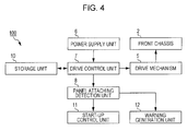
Fig. 4 is a block diagram of an on-vehicle electronic device according to a second embodiment of the present invention; and -
Fig. 5 is a flowchart of an operation control method for the on-vehicle electronic device according to the second embodiment of the present invention. - In the following, an on-vehicle electronic device according to a first embodiment of the present invention will be described with reference to
Figs. 1A, 1B , and2 . - As illustrated in
Figs. 1A and 1B , an on-vehicleelectronic device 100 in the first embodiment includes afront chassis 2 having a plate-like shape and arranged near afront surface 1a of a main unit 1 of the on-vehicleelectronic device 100. Thefront chassis 2 includes, for example, a detaching/attaching mechanism that provides easy mating and unmating of a front panel 3 illustrated inFig. 1B , an electrode terminal used to supply power to drive the front panel 3, and the like, the detaching/attaching mechanism and the electrode terminal being not illustrated. In addition, the front panel 3 includes a display unit, various operation buttons, a mechanism that engages the detaching/attaching mechanism of thefront chassis 2, an electrode terminal that receives power supplied from the electrode terminal of thefront chassis 2, and the like. Note that an existing mechanism may be applied as the detaching/attaching mechanism. - As illustrated in
Figs. 1A and 1B , the on-vehicleelectronic device 100 includes adrive mechanism 5 that makes thefront chassis 2 tilt, that is, that makes thefront chassis 2 move so as to form a certain angle with thefront surface 1a of the main unit 1. As illustrated inFigs. 1A and 1B , a bottom portion of thefront chassis 2 is coupled to a front end of thedrive mechanism 5 in a rotatable manner. Thedrive mechanism 5 may include aslide member 51, adrive source 52, and a transmission system 53. Theslide member 51 is capable of sliding in a fore-and-aft manner (in the side to side directions inFigs. 1A and 1B ). Thedrive source 52 includes a motor that drives theslide member 51. The transmission system 53 includes a plurality of gears used to convert driving force of thedrive source 52 into sliding movement of theslide member 51. In this case, thefront chassis 2 is angled in accordance with the length of a projected portion of theslide member 51 from thefront surface 1a of the main unit 1. Note that a technology described in, for example, Japanese Unexamined Patent Application Publication No.2000-40882 2000-76838 drive mechanism 5. Moreover, when needed, an existing guide mechanism may be provided on thefront surface 1a of the main unit 1 in order to guide tilting of thefront chassis 2. - The main unit 1 is covered by a housing having a rectangular parallelepiped shape. A navigation unit, a disc drive unit that plays back CDs or DVDs, an amplifier that amplifies sound signals, and the like are contained in the housing. None of the navigation unit, the disc drive unit, and the amplifier is illustrated.
- Furthermore, as illustrated in
Fig. 2 , the on-vehicleelectronic device 100 includes apower supply unit 6 as a power supply device. Power supply in the on-vehicleelectronic device 100 is performed by thepower supply unit 6. Thepower supply unit 6 may include, for example, an electric circuit, a control unit, and the like. The electric circuit is connected to a battery of a vehicle. The control unit electrically controls, by a switching operation or the like, power supply from the battery via the electric circuit in the on-vehicleelectronic device 100. In addition, thepower supply unit 6 may start power supply upon detecting at least one of turning on of an accessory (ACC) switch of the vehicle, opening of a door of the vehicle, unlocking of a door of the vehicle, and a user approaching the vehicle. Note that, in this case, it is necessary that thepower supply unit 6 includes an approach detection sensor that is electrically and directly or wirelessly connected to an ACC power supply circuit that detects turning on of ACC of the vehicle, a door sensor that detects opening of a door of the vehicle, a door lock sensor that detects whether a door of the vehicle is being in a locked state or an unlocked state, a smart-key detection circuit that detects a user approaching the vehicle, and the like. - Furthermore, as illustrated in
Fig. 2 , the on-vehicleelectronic device 100 includes adrive control unit 7 as a drive control device. When thepower supply unit 6 starts power supply, thedrive control unit 7 performs drive control on thedrive mechanism 5 such that thefront chassis 2 is tilted from an initial position to a panel attachment waiting position. At the initial position, thefront chassis 2 lies along thefront surface 1a of the main unit 1 (thefront chassis 2 is arranged almost parallel to thefront surface 1a). At the panel attachment waiting position, thefront chassis 2 forms a certain angle with thefront surface 1a. Such drive control is performed without performing determination as to whether or not the front panel 3 is attached to thefront chassis 2. Here,Fig. 1A illustrates a state in which thefront chassis 2 is positioned upright at the initial position. In contrast,Fig. 1B illustrates a state in which thefront chassis 2 is tilted to the panel attachment waiting position and thefront chassis 2 forms a certain angle with thefront surface 1a. Here, a certain angle that defines the panel attachment waiting position may be an angle preset by a manufacturer or a user, an angle formed when the on-vehicleelectronic device 100 was last used, or an angle formed when attachment of the front panel 3 was last performed. It is desirable that data regarding such a certain angle (for example, the data may be data regarding the number of revolutions of the motor included in thedrive source 52 corresponding to a certain angle from the initial position) be stored in astorage unit 10 constituted by a semiconductor memory and the like, in a state in which thedrive control unit 7 is capable of reading the data. In addition, thedrive control unit 7 may perform drive control on thedrive mechanism 5 by controlling power supply to the drive mechanism 5 (drive source 52), the power supply being performed by thepower supply unit 6. Furthermore, thedrive control unit 7 may be realized by executing a program (a operation control program) that realizes functions of thedrive control unit 7 and is stored in a read-only memory (ROM) or the like, the execution being performed by a processing unit (a computer) such as a central processing unit (CPU). In this case, the processing unit may perform processing using a work area such as a random-access memory (RAM). - Moreover, as illustrated in
Fig. 2 , the on-vehicleelectronic device 100 includes a panel attachingdetection unit 8 as a panel attaching detection device. The panel attachingdetection unit 8 detects whether or not the front panel 3 is attached to thefront chassis 2 after thefront chassis 2 has been tilted to or while thefront chassis 2 is being tilted to the panel attachment waiting position by drive control performed by thedrive control unit 7. The panel attachingdetection unit 8 may detect that the front panel 3 has been attached to thefront chassis 2, by electrically detecting that power is being successfully supplied to the front panel 3. Alternatively, the panel attachingdetection unit 8 may detect that the front panel 3 has been attached to thefront chassis 2, by using a mechanical switch or an optical switch that performs output switching when the front panel 3 is attached to thefront chassis 2. Moreover, the panel attachingdetection unit 8 may be realized by executing a program that realizes functions of the panel attachingdetection unit 8, the execution being performed by a processing unit. Note that when the panel attachingdetection unit 8 detects whether or not the front panel 3 is attached to thefront chassis 2 whilefront chassis 2 is being tilted to the panel attachment waiting position, it is possible to start up the on-vehicleelectronic device 100 faster, which will be described later. - Furthermore, as illustrated in
Fig. 2 , the on-vehicleelectronic device 100 includes a start-upcontrol unit 11 as a start-up control device. In the case where the panel attachingdetection unit 8 has detected that the front panel 3 is attached to thefront chassis 2, the start-upcontrol unit 11 starts up the on-vehicleelectronic device 100 and makes the on-vehicleelectronic device 100 enter a state in which the on-vehicleelectronic device 100 is usable. Here, "usable" refers to a state in which the main function of the on-vehicleelectronic device 100 is usable by performing input (a button operation or the like), output (image display or the like), or both via the front panel 3. Moreover, the position of thefront chassis 2 when the on-vehicleelectronic device 100 starts up may be the panel attachment waiting position, a position whose angle with respect to thefront surface 1a is smaller than that of the panel attachment waiting position, or a position whose angle with respect to thefront surface 1a is larger than that of the panel attachment waiting position. In contrast, in the case where the panel attachingdetection unit 8 has detected that the front panel 3 is not attached to thefront chassis 2, the start-upcontrol unit 11 puts the on-vehicleelectronic device 100 on standby until the panel attachingdetection unit 8 detects that the front panel 3 has been attached to thefront chassis 2 at which point the on-vehicleelectronic device 100 starts up. The start-upcontrol unit 11 may be realized by executing a program that realizes functions of the start-upcontrol unit 11, the execution being performed by a processing unit. - With such a structure, after supplying of power in the on-vehicle
electronic device 100 has been started and thefront chassis 2 has been tilted from the initial position to the panel attachment waiting position, it is possible to put thefront chassis 2 on standby in order to allow attachment of the front panel 3 to thefront chassis 2. Thus, the front panel 3 may be easily attached to thefront chassis 2 at the panel attachment waiting position. That is, since thefront chassis 2 forms an angel with thefront surface 1a of the main unit 1, an issue tends not to come up such that hands and fingers of a user who holds the outer edge of the front panel 3 touch an instrument panel portion of the vehicle positioned around thefront chassis 2, which makes it difficult to attach the front panel 3 to thefront chassis 2. - Next, an operation control method for an on-vehicle electronic device according to the first embodiment of the present invention will be described with reference to
Fig. 3 , the first embodiment employing the on-vehicleelectronic device 100. - Note that, in the initial state, the
front chassis 2 is at the initial position as illustrated inFig. 1A . - In step 1 (ST1) in
Fig. 3 , it is determined in the initial state whether or not thepower supply unit 6 has triggered starting of power supply. As described above, starting of power supply may be triggered upon detection of at least one of turning on of an accessory (ACC) switch of the vehicle, opening of a door of the vehicle, unlocking of a door of the vehicle, and a user approaching the vehicle. If YES in step 1 (ST1), the procedure proceeds to step 2 (ST2). If NO in step 1 (ST1), the procedure returns to step 1 (ST1). - Next, in step 2 (ST2), the
drive control unit 7 performs drive control on thedrive mechanism 5 on the basis of the operation control program and makes thefront chassis 2 move from the initial position to the panel attachment waiting position illustrated inFig. 1B . - Next, in step 3 (ST3), the panel attaching
detection unit 8 detects whether or not the front panel 3 is attached to thefront chassis 2 after thefront chassis 2 has been moved to or while thefront chassis 2 is being moved to the panel attachment waiting position in step 2 (ST2). If it is detected that the front panel 3 is attached to thefront chassis 2 in step 3 (ST3) (that is, in the case of YES), the procedure proceeds to step 4(ST4). If a negative detection result is obtained in step 3 (ST3), that is, it is detected that the front panel 3 is not attached to the front chassis 2 (that is, in the case of NO), the procedure proceeds to step 5 (ST5). - Here, when the procedure proceeds to step 4 (ST4), on the basis of the operation control program, the start-up
control unit 11 starts up the on-vehicleelectronic device 100 and makes the on-vehicle electronic device enter a state in which the on-vehicleelectronic device 100 is usable, and completes processing. - In contrast, when the procedure proceeds to step 5 (ST5), on the basis of the operation control program, the start-up
control unit 11 starts putting or continues maintaining the on-vehicleelectronic device 100 on standby before start-up, and the procedure returns to step 3 (ST3). Here, in the case where step 5 (ST5) is executed for the first time, processing for putting the on-vehicleelectronic device 100 on standby before start-up is "started" in step 5 (ST5). In contrast, in the case where the procedure returns to step 3 (ST3) and step 5 (ST5) has already been executed at least once, processing for maintaining the on-vehicleelectronic device 100 on standby before start-up is "continued" in step 5 (ST5). - Next, an on-vehicle electronic device according to a second embodiment of the present invention will be described only on a difference between the first embodiment and the second embodiment with reference to
Fig. 4 . - As illustrated in
Fig. 4 , the difference between the on-vehicleelectronic device 100 according to the first embodiment and an on-vehicleelectronic device 100 according to the second embodiment is that the on-vehicleelectronic device 100 according to the second embodiment includes awarning generation unit 12, as a warning generation device. - In the case where the panel attaching
detection unit 8 has detected that the front panel 3 is not attached to thefront chassis 2 within a predetermined period of time after thefront chassis 2 has been tilted to the panel attachment waiting position (in other words, from starting of putting of the on-vehicleelectronic device 100 on standby before start-up), thewarning generation unit 12 outputs a warning to prompt a user to attach the front panel 3 to thefront chassis 2. Such a warning may be at least one of a voice message such as "please attach a panel to the front chassis" and a simple warning beep without a message. Preferably, a warning is output via a sound output unit, not illustrated, such as a speaker. Furthermore, thewarning generation unit 12 may be realized by executing a program that realizes functions of thewarning generation unit 12, the execution being performed by a processing unit. - With such a structure, the on-vehicle
electronic device 100 may help a user not to forget to attach the front panel 3 to thefront chassis 2 by outputting a warning. - Next, an operation control method for the on-vehicle electronic device according to the second embodiment of the present invention will be described only on a difference between the first embodiment and the second embodiment with reference to
Fig. 5 . - As illustrated in
Fig. 5 , the difference between the operation control method according to the first embodiment and the operation control method according to the second embodiment is that step 5' (ST5') and steps 6 (ST6) to 11 (ST11) are executed instead of step 5 (ST5) illustrated inFig. 3 . - That is, in step 5' (ST5'), the start-up
control unit 11 starts putting the on-vehicleelectronic device 100 on standby before start-up on the basis of the operation control program, and the procedure proceeds to step 6 (ST6). - Next, in step 6 (ST6), the start-up
control unit 11 determines whether or not a predetermined period of time has elapsed. If YES in step 6 (ST6), the procedure proceeds to step 7 (ST7). If NO in step 6 (ST6), the procedure proceeds to step 10 (ST10). - Here, processing in and after step 7 (ST7) will be first described. First, in step 7 (ST7), the
warning generation unit 12 outputs a warning. - Next, in step 8 (ST8), the panel attaching
detection unit 8 detects whether or not the front panel 3 is attached to thefront chassis 2. If it is detected that the front panel 3 is attached to the proofingprinter 2 in step 8 (ST8) (in the case of YES), the procedure proceeds to step 9 (ST9). If a negative detection result is obtained in step 8 (ST8) (in the case of NO), the procedure returns to step 7 (ST7) and outputting of the warning continues. - Next, in step 9 (ST9), the
warning generation unit 12 stops the warning and the procedure proceeds to step 4 (ST4). - Next, processing in and after step 10 (ST10) will be described. First, in step 10 (ST10), the panel attaching
detection unit 8 detects whether or not the front panel 3 is attached to thefront chassis 2. If it is detected that the front panel 3 is attached to thefront chassis 2 in step 10 (ST10) (in the case of YES), the procedure proceeds to step 4 (ST4). If a negative detection result is obtained in step 10 (ST10) (in the case of NO), the procedure proceeds to step 11 (ST11). - Next, in step 11 (ST11), the start-up
control unit 11 continues maintaining the on-vehicleelectronic device 100 on standby before start-up on the basis of the operation control program, and the procedure returns to step 6 (ST6). - Note that the present invention is not limited to the above-described embodiments. A variety of modifications and changes may be made without departing from the scope of the present invention.
- For example, in order to easily detach the front panel 3 from the
front chassis 2 while thefront chassis 2 is in a tilted state after the on-vehicleelectronic device 100 is used, thedrive control unit 7 may hold thefront chassis 2 for a predetermined period of time at a position to which thefront chassis 2 has been tilted even after driving of the on-vehicleelectronic device 100 is commanded to stop, without immediately returning thefront chassis 2 to the initial position. The position to which thefront chassis 2 has been tilted may be the panel attachment waiting position described above. - In addition, in the above-described embodiments, as a specific unit that makes the
front chassis 2 tilt to the panel attachment waiting position, thedrive control unit 7 performs drive control on thedrive mechanism 5 in accordance with a certain angle prestored for thefront chassis 2. However, in addition to this, for example, a sensor is provided that optically detects that thefront chassis 2 has been tilted to the panel attachment waiting position, and thedrive control unit 7 may perform drive control on thedrive mechanism 5 until thefront chassis 2 reaches a position detected by the sensor.
Claims (8)
- An on-vehicle electronic device (100) that includes a front chassis (2) that is arranged near a front surface (1a) of the main unit (1) of the on-vehicle electronic device (100) such that the front chassis (2) is capable of tilting and from which and to which a panel (3) is detachable/attachable, and
a drive mechanism (5) that makes the front chassis (2) tilt with respect to the front surface (1a) of the main unit (1) of the on-vehicle electronic device (100), the on-vehicle electronic device (100) comprising:a power supply unit (6) that performs power supply to the main unit (1) of the on-vehicle electronic device (100);a drive control unit (7) that performs drive control on the drive mechanism such that the front chassis (2) is tilted from an initial position, in which the front chassis (2) lies along the front surface (1a) of the main unit (1) of the on-vehicle electronic device (100), to a panel attachment waiting position, in which the front chassis (2) forms a certain angle with the front surface (1a) of the main unit (1) of the on-vehicle electronic device (100), the drive control being triggered by starting of the power supply performed by the power supply unit (6);a panel attaching detection unit (8) that detects whether or not the panel (3) is attached to the front chassis (2), after the front chassis (2) has been tilted to or while the front chassis (2) is being tilted to the panel attachment waiting position by drive control performed by the drive control unit (7); anda start-up control unit (11) that, in the case where the panel attaching detection unit (8) has detected that the panel (3) is attached to the front chassis (2), starts up the main unit (1) of the on-vehicle electronic device (100) and makes the on-vehicle electronic device (100) enter a state in which the main unit (1) of the on-vehicle electronic device (100) is usable and that, in the case where the panel attaching detection unit (8) has detected that the panel (3) is not attached to the front chassis (2), puts the main unit (1) of the on-vehicle electronic device (100) on standby until the panel attaching detection unit (8) detects that the panel (3) has been attached to the front chassis (2) at which point the main unit (1) of the on-vehicle electronic device (100) starts up. - The on-vehicle electronic device (100) according to Claim 1, wherein the certain angle is a preset angle, an angle formed when the on-vehicle electronic device (100) was last used, or an angle formed when attachment of the panel (3) was last performed.
- The on-vehicle electronic device (100) according to Claim 1 or 2, wherein the power supply unit (6) starts power supply upon detecting at least one of turning on of an accessory switch of the vehicle, opening of a door of the vehicle, unlocking of a door of the vehicle, and a user approaching the vehicle.
- The on-vehicle electronic device (100) according to any one of Claims 1 to 3, further comprising a warning generation unit (12) that outputs a warning to prompt a user to attach the panel (3) to the front chassis (2), the warning being constituted by a voice message, a warning beep, or both, in the case where it has been detected that the panel (3) is not attached to the front chassis (2) within a predetermined period of time after the front chassis (2) has been tilted to the panel attachment waiting position.
- An operation control method for an on-vehicle electronic device (100) that includes a front chassis (2) that is arranged near a front surface (1a) of the main unit (1) of the on-vehicle electronic device (100) such that the front chassis (2) is capable of tilting and from which and to which a panel (3) is detachable/attachable, and
a drive mechanism (5) that makes the front chassis (2) tilt with respect to the front surface (1a) of the main unit (1) of the on-vehicle electronic device (100), the operation control method comprising:a first step of starting power supply to the main unit (1) of the on-vehicle electronic device (100);a second step (ST2) of performing drive control on the drive mechanism such that the front chassis (2) is tilted from an initial position, in which the front chassis (2) lies along the front surface (1a) of the main unit (1) of the on-vehicle electronic device (100), to a panel attachment waiting position, in which the front chassis (2) forms a certain angle with the front surface (1a) of the main unit (1) of the on-vehicle electronic device (100), the drive control being triggered by starting of the power supply in the first step;a third step (ST3) of detecting whether or not the panel (3) is attached to the front chassis (2), after the front chassis (2) has been tilted to or while the front chassis (2) is being tilted to the panel attachment waiting position in the second step (ST2);in the case where it has been detected that the panel (3) is attached to the front chassis (2) in the third step, a fourth step (ST4) of starting up the main unit (1) of the on-vehicle electronic device (100) and making the on-vehicle electronic device (100) enter a state in which the main unit (1) of the on-vehicle electronic device (100) is usable; andin the case where it has been detected that the panel (3) is not attached to the front chassis (2) in the third step, a fifth step (ST5, ST5', ST11) of putting the main unit (1) of the on-vehicle electronic device (100) on standby until it is detected that the panel (3) has been attached to the front chassis (2) at which point the main unit (1) of the on-vehicle electronic device (100) starts up. - The operation control method according to Claim 5, wherein the certain angle is a preset angle, an angle formed when the on-vehicle electronic device (100) was last used, or an angle formed when attachment of the panel (3) was last performed.
- The operation control method according to Claim 5 or 6, wherein, in the first step, power supply is started upon detection of at least one of turning on of an accessory switch of the vehicle, opening of a door of the vehicle, unlocking of a door of the vehicle, and a user approaching the vehicle.
- The operation control method according to any one of Claims 5 to 7, further comprising a sixth step (ST7) of outputting a warning to prompt a user to attach the panel (3) to the front chassis (2), the warning being constituted by a voice message, a warning beep, or both, in the case where, in the third step (ST3), it has been detected that the panel (3) is not attached to the front chassis (2) within a predetermined period of time after the front chassis (2) has been tilted to the panel attachment waiting position.
Applications Claiming Priority (1)
| Application Number | Priority Date | Filing Date | Title |
|---|---|---|---|
| JP2012231638A JP2014083864A (en) | 2012-10-19 | 2012-10-19 | In-vehicle electronic device, and operation control method and operation program thereof |
Publications (2)
| Publication Number | Publication Date |
|---|---|
| EP2722232A1 true EP2722232A1 (en) | 2014-04-23 |
| EP2722232B1 EP2722232B1 (en) | 2017-12-06 |
Family
ID=49385129
Family Applications (1)
| Application Number | Title | Priority Date | Filing Date |
|---|---|---|---|
| EP13188876.0A Not-in-force EP2722232B1 (en) | 2012-10-19 | 2013-10-16 | On-vehicle electronic device and its operation control method |
Country Status (2)
| Country | Link |
|---|---|
| EP (1) | EP2722232B1 (en) |
| JP (1) | JP2014083864A (en) |
Citations (5)
| Publication number | Priority date | Publication date | Assignee | Title |
|---|---|---|---|---|
| JP2000040882A (en) | 1998-05-21 | 2000-02-08 | Alpine Electronics Inc | Front panel device of apparatus for vehicle |
| JP2000076838A (en) | 1998-08-27 | 2000-03-14 | Alpine Electronics Inc | Front panel device for onboard apparatus |
| EP1283132A2 (en) * | 2001-08-06 | 2003-02-12 | Pioneer Corporation | Electronic apparatus, drive mechanism and drive control method for a front panel |
| JP2005206007A (en) * | 2004-01-22 | 2005-08-04 | Kenwood Corp | Electronic equipment having electric panel |
| EP2181897A2 (en) * | 2008-10-30 | 2010-05-05 | Victor Company of Japan Limited | Panel attitude changing system and electronic system and electronic equipment with panel attitude changing system |
-
2012
- 2012-10-19 JP JP2012231638A patent/JP2014083864A/en active Pending
-
2013
- 2013-10-16 EP EP13188876.0A patent/EP2722232B1/en not_active Not-in-force
Patent Citations (6)
| Publication number | Priority date | Publication date | Assignee | Title |
|---|---|---|---|---|
| JP2000040882A (en) | 1998-05-21 | 2000-02-08 | Alpine Electronics Inc | Front panel device of apparatus for vehicle |
| JP2000076838A (en) | 1998-08-27 | 2000-03-14 | Alpine Electronics Inc | Front panel device for onboard apparatus |
| EP1283132A2 (en) * | 2001-08-06 | 2003-02-12 | Pioneer Corporation | Electronic apparatus, drive mechanism and drive control method for a front panel |
| JP2005206007A (en) * | 2004-01-22 | 2005-08-04 | Kenwood Corp | Electronic equipment having electric panel |
| JP4242788B2 (en) | 2004-01-22 | 2009-03-25 | 株式会社ケンウッド | In-vehicle electronic device having electric panel |
| EP2181897A2 (en) * | 2008-10-30 | 2010-05-05 | Victor Company of Japan Limited | Panel attitude changing system and electronic system and electronic equipment with panel attitude changing system |
Also Published As
| Publication number | Publication date |
|---|---|
| JP2014083864A (en) | 2014-05-12 |
| EP2722232B1 (en) | 2017-12-06 |
Similar Documents
| Publication | Publication Date | Title |
|---|---|---|
| JP7805418B2 (en) | Game controller attachments | |
| KR20200129645A (en) | Electronic device incluidng slide body | |
| US10106055B2 (en) | Vehicle control system, portable terminal, and vehicular device | |
| JP2019154147A (en) | Energization device | |
| EP3206394A1 (en) | Electronic mirror device | |
| KR20180044804A (en) | Lighting device that stores rotation angle of head | |
| JP2014144743A (en) | Head-up display device | |
| KR102668971B1 (en) | Electronic device including slide body having rotation type camera module | |
| JP4997989B2 (en) | State control device, state control method, guidance control device, and guidance control method | |
| CN108833699B (en) | Electronic device and control method and device of sliding assembly of electronic device | |
| EP2722232B1 (en) | On-vehicle electronic device and its operation control method | |
| JP2015010331A (en) | Imaging device, slide door control system, and movable body | |
| JP7403604B2 (en) | energizing device | |
| JP6134828B1 (en) | Docking device and electronic device | |
| KR101083161B1 (en) | Button type ignition switching unit and method for controlling the same | |
| JP2016057987A (en) | Small-sized electronic apparatus | |
| JP4122183B2 (en) | Display unit control device | |
| JP6062725B2 (en) | Holding system, communication system, and holding method | |
| US20110271592A1 (en) | Apparatus with opening and closing mechanism | |
| JP6116288B2 (en) | Automotive electronic devices | |
| JP6175916B2 (en) | Vehicle member mounting structure | |
| JP6061717B2 (en) | Automotive electronic devices | |
| JP2009120053A (en) | On-vehicle equipment, and method and program for controlling the same | |
| EP4464539A1 (en) | Motor vehicle with releasable electric charging port | |
| JP5150121B2 (en) | Electronic device with display device, control method thereof, and control program |
Legal Events
| Date | Code | Title | Description |
|---|---|---|---|
| PUAI | Public reference made under article 153(3) epc to a published international application that has entered the european phase |
Free format text: ORIGINAL CODE: 0009012 |
|
| AK | Designated contracting states |
Kind code of ref document: A1 Designated state(s): AL AT BE BG CH CY CZ DE DK EE ES FI FR GB GR HR HU IE IS IT LI LT LU LV MC MK MT NL NO PL PT RO RS SE SI SK SM TR |
|
| AX | Request for extension of the european patent |
Extension state: BA ME |
|
| 17P | Request for examination filed |
Effective date: 20140929 |
|
| RBV | Designated contracting states (corrected) |
Designated state(s): AL AT BE BG CH CY CZ DE DK EE ES FI FR GB GR HR HU IE IS IT LI LT LU LV MC MK MT NL NO PL PT RO RS SE SI SK SM TR |
|
| GRAP | Despatch of communication of intention to grant a patent |
Free format text: ORIGINAL CODE: EPIDOSNIGR1 |
|
| INTG | Intention to grant announced |
Effective date: 20170704 |
|
| GRAS | Grant fee paid |
Free format text: ORIGINAL CODE: EPIDOSNIGR3 |
|
| GRAJ | Information related to disapproval of communication of intention to grant by the applicant or resumption of examination proceedings by the epo deleted |
Free format text: ORIGINAL CODE: EPIDOSDIGR1 |
|
| GRAL | Information related to payment of fee for publishing/printing deleted |
Free format text: ORIGINAL CODE: EPIDOSDIGR3 |
|
| GRAR | Information related to intention to grant a patent recorded |
Free format text: ORIGINAL CODE: EPIDOSNIGR71 |
|
| INTC | Intention to grant announced (deleted) | ||
| GRAA | (expected) grant |
Free format text: ORIGINAL CODE: 0009210 |
|
| INTG | Intention to grant announced |
Effective date: 20171009 |
|
| AK | Designated contracting states |
Kind code of ref document: B1 Designated state(s): AL AT BE BG CH CY CZ DE DK EE ES FI FR GB GR HR HU IE IS IT LI LT LU LV MC MK MT NL NO PL PT RO RS SE SI SK SM TR |
|
| REG | Reference to a national code |
Ref country code: GB Ref legal event code: FG4D |
|
| REG | Reference to a national code |
Ref country code: AT Ref legal event code: REF Ref document number: 952084 Country of ref document: AT Kind code of ref document: T Effective date: 20171215 Ref country code: CH Ref legal event code: EP |
|
| REG | Reference to a national code |
Ref country code: IE Ref legal event code: FG4D |
|
| REG | Reference to a national code |
Ref country code: DE Ref legal event code: R096 Ref document number: 602013030337 Country of ref document: DE |
|
| REG | Reference to a national code |
Ref country code: NL Ref legal event code: MP Effective date: 20171206 |
|
| REG | Reference to a national code |
Ref country code: LT Ref legal event code: MG4D |
|
| PG25 | Lapsed in a contracting state [announced via postgrant information from national office to epo] |
Ref country code: LT Free format text: LAPSE BECAUSE OF FAILURE TO SUBMIT A TRANSLATION OF THE DESCRIPTION OR TO PAY THE FEE WITHIN THE PRESCRIBED TIME-LIMIT Effective date: 20171206 Ref country code: ES Free format text: LAPSE BECAUSE OF FAILURE TO SUBMIT A TRANSLATION OF THE DESCRIPTION OR TO PAY THE FEE WITHIN THE PRESCRIBED TIME-LIMIT Effective date: 20171206 Ref country code: FI Free format text: LAPSE BECAUSE OF FAILURE TO SUBMIT A TRANSLATION OF THE DESCRIPTION OR TO PAY THE FEE WITHIN THE PRESCRIBED TIME-LIMIT Effective date: 20171206 Ref country code: NO Free format text: LAPSE BECAUSE OF FAILURE TO SUBMIT A TRANSLATION OF THE DESCRIPTION OR TO PAY THE FEE WITHIN THE PRESCRIBED TIME-LIMIT Effective date: 20180306 Ref country code: SE Free format text: LAPSE BECAUSE OF FAILURE TO SUBMIT A TRANSLATION OF THE DESCRIPTION OR TO PAY THE FEE WITHIN THE PRESCRIBED TIME-LIMIT Effective date: 20171206 |
|
| REG | Reference to a national code |
Ref country code: AT Ref legal event code: MK05 Ref document number: 952084 Country of ref document: AT Kind code of ref document: T Effective date: 20171206 |
|
| PG25 | Lapsed in a contracting state [announced via postgrant information from national office to epo] |
Ref country code: RS Free format text: LAPSE BECAUSE OF FAILURE TO SUBMIT A TRANSLATION OF THE DESCRIPTION OR TO PAY THE FEE WITHIN THE PRESCRIBED TIME-LIMIT Effective date: 20171206 Ref country code: GR Free format text: LAPSE BECAUSE OF FAILURE TO SUBMIT A TRANSLATION OF THE DESCRIPTION OR TO PAY THE FEE WITHIN THE PRESCRIBED TIME-LIMIT Effective date: 20180307 Ref country code: LV Free format text: LAPSE BECAUSE OF FAILURE TO SUBMIT A TRANSLATION OF THE DESCRIPTION OR TO PAY THE FEE WITHIN THE PRESCRIBED TIME-LIMIT Effective date: 20171206 Ref country code: BG Free format text: LAPSE BECAUSE OF FAILURE TO SUBMIT A TRANSLATION OF THE DESCRIPTION OR TO PAY THE FEE WITHIN THE PRESCRIBED TIME-LIMIT Effective date: 20180306 Ref country code: HR Free format text: LAPSE BECAUSE OF FAILURE TO SUBMIT A TRANSLATION OF THE DESCRIPTION OR TO PAY THE FEE WITHIN THE PRESCRIBED TIME-LIMIT Effective date: 20171206 |
|
| PG25 | Lapsed in a contracting state [announced via postgrant information from national office to epo] |
Ref country code: NL Free format text: LAPSE BECAUSE OF FAILURE TO SUBMIT A TRANSLATION OF THE DESCRIPTION OR TO PAY THE FEE WITHIN THE PRESCRIBED TIME-LIMIT Effective date: 20171206 |
|
| PG25 | Lapsed in a contracting state [announced via postgrant information from national office to epo] |
Ref country code: EE Free format text: LAPSE BECAUSE OF FAILURE TO SUBMIT A TRANSLATION OF THE DESCRIPTION OR TO PAY THE FEE WITHIN THE PRESCRIBED TIME-LIMIT Effective date: 20171206 Ref country code: CZ Free format text: LAPSE BECAUSE OF FAILURE TO SUBMIT A TRANSLATION OF THE DESCRIPTION OR TO PAY THE FEE WITHIN THE PRESCRIBED TIME-LIMIT Effective date: 20171206 Ref country code: SK Free format text: LAPSE BECAUSE OF FAILURE TO SUBMIT A TRANSLATION OF THE DESCRIPTION OR TO PAY THE FEE WITHIN THE PRESCRIBED TIME-LIMIT Effective date: 20171206 |
|
| PG25 | Lapsed in a contracting state [announced via postgrant information from national office to epo] |
Ref country code: PL Free format text: LAPSE BECAUSE OF FAILURE TO SUBMIT A TRANSLATION OF THE DESCRIPTION OR TO PAY THE FEE WITHIN THE PRESCRIBED TIME-LIMIT Effective date: 20171206 Ref country code: AT Free format text: LAPSE BECAUSE OF FAILURE TO SUBMIT A TRANSLATION OF THE DESCRIPTION OR TO PAY THE FEE WITHIN THE PRESCRIBED TIME-LIMIT Effective date: 20171206 Ref country code: IT Free format text: LAPSE BECAUSE OF FAILURE TO SUBMIT A TRANSLATION OF THE DESCRIPTION OR TO PAY THE FEE WITHIN THE PRESCRIBED TIME-LIMIT Effective date: 20171206 Ref country code: RO Free format text: LAPSE BECAUSE OF FAILURE TO SUBMIT A TRANSLATION OF THE DESCRIPTION OR TO PAY THE FEE WITHIN THE PRESCRIBED TIME-LIMIT Effective date: 20171206 Ref country code: SM Free format text: LAPSE BECAUSE OF FAILURE TO SUBMIT A TRANSLATION OF THE DESCRIPTION OR TO PAY THE FEE WITHIN THE PRESCRIBED TIME-LIMIT Effective date: 20171206 |
|
| REG | Reference to a national code |
Ref country code: DE Ref legal event code: R097 Ref document number: 602013030337 Country of ref document: DE |
|
| PLBE | No opposition filed within time limit |
Free format text: ORIGINAL CODE: 0009261 |
|
| STAA | Information on the status of an ep patent application or granted ep patent |
Free format text: STATUS: NO OPPOSITION FILED WITHIN TIME LIMIT |
|
| REG | Reference to a national code |
Ref country code: FR Ref legal event code: PLFP Year of fee payment: 6 |
|
| 26N | No opposition filed |
Effective date: 20180907 |
|
| PG25 | Lapsed in a contracting state [announced via postgrant information from national office to epo] |
Ref country code: DK Free format text: LAPSE BECAUSE OF FAILURE TO SUBMIT A TRANSLATION OF THE DESCRIPTION OR TO PAY THE FEE WITHIN THE PRESCRIBED TIME-LIMIT Effective date: 20171206 Ref country code: SI Free format text: LAPSE BECAUSE OF FAILURE TO SUBMIT A TRANSLATION OF THE DESCRIPTION OR TO PAY THE FEE WITHIN THE PRESCRIBED TIME-LIMIT Effective date: 20171206 |
|
| REG | Reference to a national code |
Ref country code: CH Ref legal event code: PL |
|
| REG | Reference to a national code |
Ref country code: BE Ref legal event code: MM Effective date: 20181031 |
|
| PG25 | Lapsed in a contracting state [announced via postgrant information from national office to epo] |
Ref country code: MC Free format text: LAPSE BECAUSE OF FAILURE TO SUBMIT A TRANSLATION OF THE DESCRIPTION OR TO PAY THE FEE WITHIN THE PRESCRIBED TIME-LIMIT Effective date: 20171206 Ref country code: LU Free format text: LAPSE BECAUSE OF NON-PAYMENT OF DUE FEES Effective date: 20181016 |
|
| REG | Reference to a national code |
Ref country code: IE Ref legal event code: MM4A |
|
| PG25 | Lapsed in a contracting state [announced via postgrant information from national office to epo] |
Ref country code: CH Free format text: LAPSE BECAUSE OF NON-PAYMENT OF DUE FEES Effective date: 20181031 Ref country code: LI Free format text: LAPSE BECAUSE OF NON-PAYMENT OF DUE FEES Effective date: 20181031 Ref country code: BE Free format text: LAPSE BECAUSE OF NON-PAYMENT OF DUE FEES Effective date: 20181031 |
|
| PG25 | Lapsed in a contracting state [announced via postgrant information from national office to epo] |
Ref country code: IE Free format text: LAPSE BECAUSE OF NON-PAYMENT OF DUE FEES Effective date: 20181016 |
|
| PG25 | Lapsed in a contracting state [announced via postgrant information from national office to epo] |
Ref country code: MT Free format text: LAPSE BECAUSE OF NON-PAYMENT OF DUE FEES Effective date: 20181016 |
|
| PG25 | Lapsed in a contracting state [announced via postgrant information from national office to epo] |
Ref country code: TR Free format text: LAPSE BECAUSE OF FAILURE TO SUBMIT A TRANSLATION OF THE DESCRIPTION OR TO PAY THE FEE WITHIN THE PRESCRIBED TIME-LIMIT Effective date: 20171206 |
|
| PG25 | Lapsed in a contracting state [announced via postgrant information from national office to epo] |
Ref country code: PT Free format text: LAPSE BECAUSE OF FAILURE TO SUBMIT A TRANSLATION OF THE DESCRIPTION OR TO PAY THE FEE WITHIN THE PRESCRIBED TIME-LIMIT Effective date: 20171206 |
|
| PG25 | Lapsed in a contracting state [announced via postgrant information from national office to epo] |
Ref country code: CY Free format text: LAPSE BECAUSE OF FAILURE TO SUBMIT A TRANSLATION OF THE DESCRIPTION OR TO PAY THE FEE WITHIN THE PRESCRIBED TIME-LIMIT Effective date: 20171206 Ref country code: MK Free format text: LAPSE BECAUSE OF NON-PAYMENT OF DUE FEES Effective date: 20171206 Ref country code: HU Free format text: LAPSE BECAUSE OF FAILURE TO SUBMIT A TRANSLATION OF THE DESCRIPTION OR TO PAY THE FEE WITHIN THE PRESCRIBED TIME-LIMIT; INVALID AB INITIO Effective date: 20131016 |
|
| PG25 | Lapsed in a contracting state [announced via postgrant information from national office to epo] |
Ref country code: AL Free format text: LAPSE BECAUSE OF FAILURE TO SUBMIT A TRANSLATION OF THE DESCRIPTION OR TO PAY THE FEE WITHIN THE PRESCRIBED TIME-LIMIT Effective date: 20171206 Ref country code: IS Free format text: LAPSE BECAUSE OF FAILURE TO SUBMIT A TRANSLATION OF THE DESCRIPTION OR TO PAY THE FEE WITHIN THE PRESCRIBED TIME-LIMIT Effective date: 20180406 |
|
| PGFP | Annual fee paid to national office [announced via postgrant information from national office to epo] |
Ref country code: GB Payment date: 20211022 Year of fee payment: 9 Ref country code: DE Payment date: 20211020 Year of fee payment: 9 |
|
| PGFP | Annual fee paid to national office [announced via postgrant information from national office to epo] |
Ref country code: FR Payment date: 20211022 Year of fee payment: 9 |
|
| REG | Reference to a national code |
Ref country code: DE Ref legal event code: R119 Ref document number: 602013030337 Country of ref document: DE |
|
| GBPC | Gb: european patent ceased through non-payment of renewal fee |
Effective date: 20221016 |
|
| PG25 | Lapsed in a contracting state [announced via postgrant information from national office to epo] |
Ref country code: FR Free format text: LAPSE BECAUSE OF NON-PAYMENT OF DUE FEES Effective date: 20221031 Ref country code: DE Free format text: LAPSE BECAUSE OF NON-PAYMENT OF DUE FEES Effective date: 20230503 |
|
| PG25 | Lapsed in a contracting state [announced via postgrant information from national office to epo] |
Ref country code: GB Free format text: LAPSE BECAUSE OF NON-PAYMENT OF DUE FEES Effective date: 20221016 |