EP2722200A1 - Pneumatic tire - Google Patents
Pneumatic tire Download PDFInfo
- Publication number
- EP2722200A1 EP2722200A1 EP12802724.0A EP12802724A EP2722200A1 EP 2722200 A1 EP2722200 A1 EP 2722200A1 EP 12802724 A EP12802724 A EP 12802724A EP 2722200 A1 EP2722200 A1 EP 2722200A1
- Authority
- EP
- European Patent Office
- Prior art keywords
- bead
- winding
- adjacent
- start end
- terminal end
- Prior art date
- Legal status (The legal status is an assumption and is not a legal conclusion. Google has not performed a legal analysis and makes no representation as to the accuracy of the status listed.)
- Granted
Links
- 239000011324 bead Substances 0.000 claims abstract description 332
- 230000002093 peripheral effect Effects 0.000 claims abstract description 49
- 239000010410 layer Substances 0.000 description 42
- 230000000052 comparative effect Effects 0.000 description 11
- 238000010008 shearing Methods 0.000 description 11
- 230000000694 effects Effects 0.000 description 10
- 238000004804 winding Methods 0.000 description 10
- 238000011156 evaluation Methods 0.000 description 7
- 238000004519 manufacturing process Methods 0.000 description 7
- 230000000116 mitigating effect Effects 0.000 description 4
- 230000002411 adverse Effects 0.000 description 3
- 230000007423 decrease Effects 0.000 description 3
- 230000002708 enhancing effect Effects 0.000 description 2
- XXZCIYUJYUESMD-UHFFFAOYSA-N 2-[4-[2-(2,3-dihydro-1H-inden-2-ylamino)pyrimidin-5-yl]-3-(morpholin-4-ylmethyl)pyrazol-1-yl]-1-(2,4,6,7-tetrahydrotriazolo[4,5-c]pyridin-5-yl)ethanone Chemical compound C1C(CC2=CC=CC=C12)NC1=NC=C(C=N1)C=1C(=NN(C=1)CC(=O)N1CC2=C(CC1)NN=N2)CN1CCOCC1 XXZCIYUJYUESMD-UHFFFAOYSA-N 0.000 description 1
- WWSJZGAPAVMETJ-UHFFFAOYSA-N 2-[4-[2-(2,3-dihydro-1H-inden-2-ylamino)pyrimidin-5-yl]-3-ethoxypyrazol-1-yl]-1-(2,4,6,7-tetrahydrotriazolo[4,5-c]pyridin-5-yl)ethanone Chemical compound C1C(CC2=CC=CC=C12)NC1=NC=C(C=N1)C=1C(=NN(C=1)CC(=O)N1CC2=C(CC1)NN=N2)OCC WWSJZGAPAVMETJ-UHFFFAOYSA-N 0.000 description 1
- FYELSNVLZVIGTI-UHFFFAOYSA-N 2-[4-[2-(2,3-dihydro-1H-inden-2-ylamino)pyrimidin-5-yl]-5-ethylpyrazol-1-yl]-1-(2,4,6,7-tetrahydrotriazolo[4,5-c]pyridin-5-yl)ethanone Chemical compound C1C(CC2=CC=CC=C12)NC1=NC=C(C=N1)C=1C=NN(C=1CC)CC(=O)N1CC2=C(CC1)NN=N2 FYELSNVLZVIGTI-UHFFFAOYSA-N 0.000 description 1
- 239000002131 composite material Substances 0.000 description 1
- 230000003247 decreasing effect Effects 0.000 description 1
- 239000011229 interlayer Substances 0.000 description 1
- 238000000034 method Methods 0.000 description 1
- XLYOFNOQVPJJNP-UHFFFAOYSA-N water Substances O XLYOFNOQVPJJNP-UHFFFAOYSA-N 0.000 description 1
Images



Classifications
-
- B—PERFORMING OPERATIONS; TRANSPORTING
- B60—VEHICLES IN GENERAL
- B60C—VEHICLE TYRES; TYRE INFLATION; TYRE CHANGING; CONNECTING VALVES TO INFLATABLE ELASTIC BODIES IN GENERAL; DEVICES OR ARRANGEMENTS RELATED TO TYRES
- B60C15/00—Tyre beads, e.g. ply turn-up or overlap
- B60C15/04—Bead cores
-
- D—TEXTILES; PAPER
- D07—ROPES; CABLES OTHER THAN ELECTRIC
- D07B—ROPES OR CABLES IN GENERAL
- D07B1/00—Constructional features of ropes or cables
- D07B1/06—Ropes or cables built-up from metal wires, e.g. of section wires around a hemp core
- D07B1/0606—Reinforcing cords for rubber or plastic articles
- D07B1/062—Reinforcing cords for rubber or plastic articles the reinforcing cords being characterised by the strand configuration
-
- B—PERFORMING OPERATIONS; TRANSPORTING
- B60—VEHICLES IN GENERAL
- B60C—VEHICLE TYRES; TYRE INFLATION; TYRE CHANGING; CONNECTING VALVES TO INFLATABLE ELASTIC BODIES IN GENERAL; DEVICES OR ARRANGEMENTS RELATED TO TYRES
- B60C15/00—Tyre beads, e.g. ply turn-up or overlap
- B60C15/04—Bead cores
- B60C2015/048—Polygonal cores characterised by the winding sequence
-
- D—TEXTILES; PAPER
- D07—ROPES; CABLES OTHER THAN ELECTRIC
- D07B—ROPES OR CABLES IN GENERAL
- D07B2201/00—Ropes or cables
- D07B2201/20—Rope or cable components
- D07B2201/2015—Strands
- D07B2201/2033—Parallel wires
-
- D—TEXTILES; PAPER
- D07—ROPES; CABLES OTHER THAN ELECTRIC
- D07B—ROPES OR CABLES IN GENERAL
- D07B2501/00—Application field
- D07B2501/20—Application field related to ropes or cables
- D07B2501/2046—Tyre cords
- D07B2501/2053—Tyre cords for wheel rim attachment
-
- Y—GENERAL TAGGING OF NEW TECHNOLOGICAL DEVELOPMENTS; GENERAL TAGGING OF CROSS-SECTIONAL TECHNOLOGIES SPANNING OVER SEVERAL SECTIONS OF THE IPC; TECHNICAL SUBJECTS COVERED BY FORMER USPC CROSS-REFERENCE ART COLLECTIONS [XRACs] AND DIGESTS
- Y10—TECHNICAL SUBJECTS COVERED BY FORMER USPC
- Y10T—TECHNICAL SUBJECTS COVERED BY FORMER US CLASSIFICATION
- Y10T152/00—Resilient tires and wheels
- Y10T152/10—Tires, resilient
- Y10T152/10495—Pneumatic tire or inner tube
- Y10T152/10819—Characterized by the structure of the bead portion of the tire
Definitions
- the present invention relates to a pneumatic tire and in particular to a pneumatic tire with a bead core embedded in a bead portion of the tire, which bead core is excellent in fracture strength and bead-expansion force and has a reduced weight.
- Examples of a bead core embedded in a bead portion of a pneumatic tire include a bead core having what is called a "mono-strand" torus structure formed by winding a strand, i.e. a rubber-coated single bead wire, plural times in a bead portion (e.g. PTL 1).
- FIG. 1 is a schematic cross sectional view of a mono-strand torus structure of a bead core as described above cut in the axial direction thereof.
- This mono-strand bead core is constituted by a strand, i.e. a rubber-coated single bead wire 1, juxtaposed in plural columns in the axial direction (the X-axis direction in FIG. 1 ) and stacked in plural rows in the radial direction (the Y-axis direction in FIG. 1 ) of the torus structure as shown in FIG. 1 .
- Such a bead core as described above is generally formed by winding a bead wire from the inner side toward the outer side in the radial direction, as shown by an arrow in FIG. 1 , because a winding process of a bead wire is normally carried out with imparting the bead wire with tension. Accordingly, a winding-start end 1s of a bead wire is normally situated on the innermost side and a winding-terminal end 1e is normally situated on the outermost side in the radial direction.
- Tensile force is hardly exerted on the respective end portions (the winding-start end 1s and the winding-terminal end 1e) of the bead wire due to characteristics of composite materials when a tire with the bead core having the aforementioned structure is inflated at an internal pressure.
- the present invention aims at solving the problems described above and an object thereof is to provide a pneumatic tire with a bead core embedded in a bead portion of the tire, which bead core is excellent in fracture strength and bead-expansion force and has a reduced weight.
- one of the main causes for fracture occurring at a winding-start end position as described above is an increase in tensile force between adjacent bead wires at the position, resulted from shearing deformation of rubber between these bead wires (see FIG. 2 ) caused by force in the direction of pulling the winding-start end of a bead wire out in the circumferential direction when a tire is inflated at an internal pressure.
- a bead core having a mono-strand torus structure as described above it is possible to enhance fracture strength and bead-expansion force by winding a strand to eventually form a U-shaped configuration with the winding-start end and the winding-terminal end thereof both situated in the outermost side in the radial direction.
- Such a bead core having a U-shaped cross sectional configuration as this can also reduce weight because the bead core has a two-column structure in the axial direction, thereby significantly narrowing the width of a bead portion as a whole.
- the inventors of the present invention newly discovered that an increase in tensile force between the adjacent bead wires at each of the end portions (i.e. the winding-start end and the winding-terminal end) of the bead wire due to shearing deformation of rubber described above can be suppressed, to enhance fracture strength of the bead core, by increasing an interval between the end portion and a bead wire constituting a layer adjacent to the end portion.
- the present invention has been contrived based on the aforementioned discoveries and main structural features are as follows.
- a bead core excellent in fracture strength and bead-expansion force it is possible to manufacture a bead core excellent in fracture strength and bead-expansion force and use the bead core in a bead portion of a pneumatic tire.
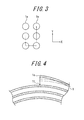
- FIG. 3 is a cross sectional view of one example of a bead core for use in a pneumatic tire of the present invention.
- This bead core has a torus structure formed by winding a strand as a rubber-coated single bead wire 1 (around a bead portion) to be juxtaposed in two columns in the axial direction of the torus structure, as shown in FIG. 3 .
- the strand is stacked in plural rows (three rows in the example of FIG. 3 ) in the radial direction of the torus structure in the bead core.
- a winding-start end 1s and a winding-terminal end 1e are situated on the outermost side in the radial direction of the respective columns in the bead core.
- Such a bead core as described above can be manufactured by winding the strand or the bead wire 1 from the outer side toward the inner side in the radial direction at one column and then from the inner side toward the outer side in the radial direction at the other column (see the arrow indicating the winding order in FIG. 3 ).
- the number of rows in the radial direction in the one column in the axial direction may differ from the number of rows in the radial direction in the other column in the axial direction, as shown in FIG. 6 and FIG. 7 , respectively.
- Such bead cores as shown in FIGS. 6 and 7 can be each manufactured by winding the strand or the bead wire 1 from the outer side toward the inner side in the radial direction at one column and then from the inner side toward the outer side in the radial direction at the other column, as is the case with the example shown in FIG. 3 (see the arrows indicating the winding orders in FIG. 6 and FIG. 7 ).
- FIG. 4 is a view showing a vicinity of an end portion of the bead wire 1 of the bead core shown in FIG. 3 .
- At least one of an interval 1t between the winding-start end 1s and an inner peripheral layer adjacent to the winding-start end 1s of the bead wire and an interval between the winding-terminal end 1e and an inner peripheral layer adjacent to the winding-terminal end 1e of the bead wire is larger than any other intervals between two adjacent bead wires (i.e. any other interlayer intervals between one bead wire layer and another bead wire layer on the inner side in the radial direction than the radially outermost interval 1t of the bead core), as shown in FIG. 4 .
- the present invention it is possible to mitigate concentration of stresses at the winding-start end and the winding-terminal end to enhance fracture strength of the bead core because the winding-start end and the winding-terminal end are each situated on the outermost side in the radial direction of the bead core.
- bead-expansion force of the bead core also enhances because neither the winding-start end nor the winding-terminal end are situated on the inner side in the radial direction.
- the bead core has a torus structure constituted of only two columns of the strand juxtaposed in the axial direction of the torus structure and thus the bead core has a significantly narrowed width, it is possible to reduce tire weight by using the bead core in a bead portion of a tire.
- the winding-start end and the winding-terminal end can be each easily positioned on the outermost side in the radial direction by winding the strand from the outer side toward the inner side in the radial direction at one column and then from the inner side toward the outer side in the radial direction at the other column as described above because the bead core as the torus structure is constituted of two columns of the strand juxtaposed in the axial direction.
- the bead core it is possible in manufacturing the bead core to prevent the winding-start end and the winding-terminal end thereof from being interfered by other bead wire layers, to enhance work efficiency and easily control an inter-wire distance between each of the winding-start end and the winding-terminal end and an inner peripheral bead wire layer adjacent thereto, because the winding-start end and the winding-terminal end are each situated on the outermost side in the radial direction of the bead core.
- the bead core for use in the tire of the present invention therefore has a merit of production easiness, as well.
- the interval between the winding-start end and an inner peripheral layer adjacent to the winding-start end, of the bead wire is preferably larger than any other intervals between two adjacent bead wires of the bead core.
- the arrangement above is preferable because it can mitigate shearing deformation of rubber between the bead wires caused by force in the direction of pulling the winding-start end out in the circumferential direction
- the interval between the winding-terminal end and an inner peripheral layer adjacent to the winding-terminal end of the bead wire, as well as the interval between the winding-start end and an inner peripheral layer adjacent to the winding-start end of the bead wire, is larger than any other intervals between two adjacent bead wires of the bead core.
- the arrangement above is preferable because it can suppress an increase in tensile force between adjacent bead wires at the respective end portions thereof when the increase occurs due to shearing deformation of rubber between each end portion and an inner peripheral layer adjacent thereto of the bead wire, thereby successfully enhancing fracture strength of the bead core.
- the interval between the winding-start end and an inner peripheral layer adjacent to the winding-start end, of the bead wire is larger than any other intervals between two adjacent bead wires of the bead core preferably in a range from the winding-start end to at least a position on the bead wire 5 mm away from the winding-start end along a circumference of the bead wire but not beyond a position on the bead wire away by one circumference from the winding-start end.
- a range in which the interval between the winding-start end and an inner peripheral layer adjacent to the winding-start end, of the bead wire, is larger than any other intervals between two adjacent bead wires of the bead core is set preferably from the winding-start end to at least a position on the bead wire 5 mm away from the winding-start end along a circumference of the bead wire but not beyond a position on the bead wire away by one circumference from the winding-start end.
- the arrangement above is preferable because: when the aforementioned range in which the interval between the winding-start end and an inner peripheral layer adjacent thereto is larger than any other intervals between two adjacent bead wires is situated on the bead wire less than 5 mm away from the winding-start end along a circumference of the bead wire, the shearing deformation of rubber described above cannot be sufficiently mitigated; and when the aforementioned range is situated on the bead wire away, by more than one circumference, from the winding-start end, an effect of mitigating shearing deformation of rubber reaches a plateau and no longer improves.
- a circumferential length of "one circumference" of the bead wire is defined, provided that a position It on the inner peripheral layer adjacent to the winding-start end 1s of the bead wire corresponds to or faces the winding-start end 1s as shown in FIG. 4 , as a circumferential length measured from the winding-start end 1s to the position 1t.
- the interval between the winding-terminal end and an inner peripheral layer adjacent to the winding-terminal end, of the bead wire is larger than any other intervals between two adjacent bead wires of the bead core preferably in a range from the winding-terminal end to at least a position on the bead wire 5 mm away from the winding-terminal end along a circumference of the bead wire but not beyond a position on the bead wire away by one circumference from the winding-terminal end.
- a range in which the interval between the winding-terminal end and an inner peripheral layer adjacent to the winding-terminal end, of the bead wire, is larger than any other intervals between two adjacent bead wires of the bead core is set preferably from the winding-terminal end to at least a position on the bead wire 5 mm away from the winding-terminal end along a circumference of the bead wire but not beyond a position on the bead wire away by one circumference from the winding-terminal end.
- the arrangement above is preferable because: when the aforementioned range in which the interval between the winding-terminal end and an inner peripheral layer adjacent thereto is larger than any other intervals between two adjacent bead wires is situated on the bead wire less than 5 mm away from the winding-terminal end along a circumference of the bead wire, the shearing deformation of rubber described above cannot be sufficiently mitigated; and when the aforementioned range is situated on the bead wire away, by more than one circumference, from the winding-terminal end, an effect of mitigating shearing deformation of rubber reaches a plateau and no longer improves.
- a circumferential length of "one circumference" of the bead wire is defined, provided that a position on the inner peripheral layer adjacent to the winding-terminal end of the bead wire corresponds to or faces the winding-terminal end, as a circumferential length measured from the winding-terminal end to the position.
- a distance between the centers of the two adjacent bead wires in the aforementioned range from the winding-start end to at least a position on the bead wire 5 mm away from the winding-start end along a circumference of the bead wire but not beyond a position on the bead wire away by one circumference from the winding-start end is preferably 1.2 to 5 times larger than a distance between the centers of the two adjacent bead wires at a position beyond said range.
- a distance between the centers of the two adjacent bead wires in the range in which the interval between the winding-start end and an inner peripheral layer adjacent thereto of the bead wire is larger than any other intervals between two adjacent bead wires of the bead core is preferably 1.2 to 5 times larger than a distance between the centers of the two adjacent bead wires at a position beyond said range.
- the arrangement above is preferable because: when a distance between the centers of the two adjacent bead wires in the aforementioned range is at least 1.2 times larger than a distance between the centers of the two adjacent bead wires at a position beyond said range, at least an effect at the minimum level required in the present invention can be ensured by a relatively small change in the bead core configuration; and when a distance between the centers of the two adjacent bead wires in the aforementioned range is not more than 5 times larger than a distance between the centers of the two adjacent bead wires at a position beyond said range, it is possible to suppress an adverse effect possibly caused on uniformity of the bead core by an unbalanced cross section of the bead core to the minimum, while sufficiently mitigating shearing deformation of rubber between the relevant bead wires.
- a distance between the centers of the two adjacent bead wires in the aforementioned range from the winding-terminal end to at least a position on the bead wire 5 mm away from the winding-terminal end along a circumference of the bead wire but not beyond a position on the bead wire away by one circumference from the winding-terminal end is preferably 1.2 to 5 times larger than a distance between the centers of the two adjacent bead wires at a position beyond said range.
- a distance between the centers of the two adjacent bead wires in the range in which the interval between the winding-terminal end and an inner peripheral layer adjacent thereto of the bead wire is larger than any other intervals between two adjacent bead wires of the bead core is preferably 1.2 to 5 times larger than a distance between the centers of the two adjacent bead wires at a position beyond said range.
- the arrangement above is preferable because: when a distance between the centers of the two adjacent bead wires in the aforementioned range is at least 1.2 times larger than a distance between the centers of the two adjacent bead wires at a position beyond said range, at least an effect at the minimum level required in the present invention can be ensured by a relatively small change in the bead core configuration; and when a distance between the centers of the two adjacent bead wires in the aforementioned range is not more than 5 times larger than a distance between the centers of the two adjacent bead wires at a position beyond said range, it is possible to suppress an adverse effect possibly caused on uniformity of the bead core by an unbalanced cross section of the bead core to the minimum, while sufficiently mitigating shearing deformation of rubber between the relevant bead wires.
- each of pneumatic test tires for Examples 1 to 3 was prepared by: manufacturing a corresponding bead core where two columns of a bead wire is juxtaposed in the axial direction, a winding-start end and a winding-terminal end of the bead wire are each situated on the outermost side in the radial direction, and at least one of an interval between the winding-start end and an inner peripheral layer adjacent to the winding-start end of the bead wire and an interval between the winding-terminal end and an inner peripheral layer adjacent to the winding-terminal end of the bead wire is larger than any other intervals between two adjacent bead wires of the bead core; and embedding the bead core in a bead portion of a tire.
- a pneumatic test tire for Comparative Example 1 was prepared by: manufacturing a corresponding bead core where two columns of a bead wire is juxtaposed in the axial direction and a winding-start end and a winding-terminal end of the bead wire are situated on the innermost side and the outermost side in the radial direction, respectively, as shown in FIG. 5 ; and embedding the bead core in a bead portion of a tire.
- a pneumatic test tire for Comparative Example 2 was prepared by: manufacturing a corresponding bead core where two columns of a bead wire is juxtaposed in the axial direction, a winding-start end and a winding-terminal end of the bead wire are each situated on the outermost side in the radial direction, but an interval between the winding-start end and an inner peripheral layer adjacent thereto of the bead wire and an interval between the winding-terminal end and an inner peripheral layer adjacent thereto of the bead wire is each equal to other intervals between two adjacent bead wires of the bead core; and embedding the bead core in a bead portion of a tire.
- Table 1 shows details of the characteristics of the respective test tires.
- a range in which the interval between the winding-start end and an inner peripheral layer adjacent thereto of the bead wire is larger than any other intervals between two adjacent bead wires of the bead core was set from the winding-start end to a position on the bead wire 5 mm away from the winding-start end along a circumference of the bead wire; and a range in which the interval between the winding-terminal end and an inner peripheral layer adj acent thereto of the bead wire is larger than any other intervals between two adjacent bead wires of the bead core was set from the winding-terminal end to a position on the bead wire 5 mm away from the winding-terminal end along a circumference of the bead wire.
- a circumferential length of "one circumference" of the bead wire is 1045 mm on each of the winding-start end side and the winding-terminal end side.
- Table 1 Figure Number of columns in the axial direction Number of rows in the radial direction Radial position of winding-start end Radial position of winding-terminal end Interval between winding-start end and inner peripheral layer adjacent thereto Interval between winding-terminal end and inner peripheral layer adjacent thereto
- Example 1 Fig. 3 2 3 Outermost side Outermost side Larger than intervals between other adjacent bead wires Larger than intervals between other adjacent bead wires Example 2 Fig.
- Fracture strength of the test tire was evaluated by a hydraulic fracture test including the steps of assembling the tire with a prescribed rim having rim size: 13 x 4.5J, injecting water into the tire, and measuring hydraulic pressure when the bead core is fractured.
- the evaluation results are expressed as index values relative to the reference value "100" for Comparative Example 1.
- the larger value represents the higher fracture strength of the sample.
- Bead-expansion force of the test tire was evaluated by: disposing a bead portion of one side of the pneumatic tire to be tested on an eight-divided rim block of a bead-expansion force tester manufactured by Hoffmann Corporation; measuring a magnitude of change in the bead portion of the tire when the bead portion is expanded toward the outer side in the radial direction; and converting the magnitude of change in the bead portion thus measured into an index value representing bead-expansion force of the tire, for evaluation.
- the evaluation results are expressed as index values relative to the reference value "100" for the bead-expansion force of Comparative Example 1.
- the larger value represents the higher bead-expansion force of the sample.
- test tires of Examples 1 to 3 are unanimously more excellent in both bead-expansion force and fracture strength than the test tire of Comparative Example 1 and unanimously more excellent in fracture strength than the test tire of Comparative Example 2.
- Example 1 a test tire for Conventional Example was prepared by embedding the conventional bead core shown in FIG. 1 in a bead portion of a tire.
- Tire weight was measured for each of the test tires of Example 1 and Conventional Example.
- the evaluation results expressed as index values relative to the reference value "100" for the tire weight of Conventional Example are shown in Table 3 below. The smaller value represents the more reduced tire weight of the sample.
- Table 3 Tire weight Example 1 98 Conventional Example 100
- test tire of Example 1 having narrower width of the bead core, exhibits more reduced tire weight than the test tire of Conventional Example.
- each of test tires for Examples 4 to 13 was prepared by changing either a ratio of a distance between the centers of the two adjacent bead wires at the winding-start end, with respect to a distance between the centers of other two adjacent bead wires, of the bead core ("Ratio of between-center distance on the winding-start end side" in Table 4) or a ratio of a distance between the centers of the two adjacent bead wires at the winding-terminal end, with respect to the distance between the centers of other two adjacent bead wires, of the bead core ("Ratio of between-center distance on the winding-terminal end side" in Table 4).
- Each of these test tires was subjected to a test for evaluating fracture strength in a manner similar to the foregoing Examples and Comparative Examples. Details of the characteristics and evaluation results of the test tires for Examples 4 to 13 are shown in Table 4.
- the evaluation results are expressed in FIG. 4 as index values relative to the reference value "100" for Comparative Example 1.
- the larger value represents the higher fracture strength of the sample.
- Example 4 Each of the test tires of Examples 4 to 13 is substantially the same as the tire of Example 1, except that the former has the characteristics shown in Table 4.
- Table 4 Ratio of between-center distance on the winding-start end side Ratio of between-center distance on the winding-terminal end side Fracture strength
- Example 4 1.1 1 101
- Example 5 1.2 1 102
- Example 6 3 1 103
- Example 7 5 1 104
- Example 8 6 1 104
- Example 9 1 1.1 101
- Example 10 1 1.2 102
- Example 11 Example 12 1 5 104
- Example 13 1 6 104
- test tires of Examples 5 to 7 and Examples 10 to 12 each having an optimum ratio of a distance between the centers of the two adjacent bead wires at the winding-start/terminal end with respect to the distance between the centers of other two adjacent bead wires, unanimously exhibit better fracture strength than the test tire of Conventional Example 1.
Landscapes
- Engineering & Computer Science (AREA)
- Mechanical Engineering (AREA)
- Tires In General (AREA)
- Tyre Moulding (AREA)
- Ropes Or Cables (AREA)
Abstract
Description
- The present invention relates to a pneumatic tire and in particular to a pneumatic tire with a bead core embedded in a bead portion of the tire, which bead core is excellent in fracture strength and bead-expansion force and has a reduced weight.
- Examples of a bead core embedded in a bead portion of a pneumatic tire include a bead core having what is called a "mono-strand" torus structure formed by winding a strand, i.e. a rubber-coated single bead wire, plural times in a bead portion (e.g. PTL 1).
-
FIG. 1 is a schematic cross sectional view of a mono-strand torus structure of a bead core as described above cut in the axial direction thereof. This mono-strand bead core is constituted by a strand, i.e. a rubber-coatedsingle bead wire 1, juxtaposed in plural columns in the axial direction (the X-axis direction inFIG. 1 ) and stacked in plural rows in the radial direction (the Y-axis direction inFIG. 1 ) of the torus structure as shown inFIG. 1 . - Such a bead core as described above is generally formed by winding a bead wire from the inner side toward the outer side in the radial direction, as shown by an arrow in
FIG. 1 , because a winding process of a bead wire is normally carried out with imparting the bead wire with tension. Accordingly, a winding-start end 1s of a bead wire is normally situated on the innermost side and a winding-terminal end 1e is normally situated on the outermost side in the radial direction. - Tensile force is hardly exerted on the respective end portions (the winding-
start end 1s and the winding-terminal end 1e) of the bead wire due to characteristics of composite materials when a tire with the bead core having the aforementioned structure is inflated at an internal pressure. - It is known that therefore fracture tends to occur at a winding-start end, in particular, due to stress concentration there when a fracture test of a mono-strand bead core is carried out.
- Further, there arises another problem in the conventional mono-strand bead core in that bead-expansion force (engaging force between a tire and a rim) decreases when the winding-start end is situated on the innermost side in the radial direction as described above.
- Yet further, development of a reduced-weight tire using as few resources as possible has been demanded in recent years in terms of environment protection and, regarding a mono-strand bead core, it is considered to reduce weight thereof by decreasing the numbers of columns in the axial direction and rows in the radial direction of the mono-strand torus structure.
- However, there arises a problem in a bead core having a reduced number of columns in the axial direction thereof in that bead-expansion force of the bead core decreases and there arises a problem in a bead core having a reduced numbers of columns in the axial direction and rows in the radial direction thereof in that fracture strength of the bead core decreases.
- There is therefore a strong demand for developing a bead core being excellent in fracture strength and bead-expansion force in spite of reduced weight thereof.
- PTL 1:
JP-A 2003-025815 - The present invention aims at solving the problems described above and an object thereof is to provide a pneumatic tire with a bead core embedded in a bead portion of the tire, which bead core is excellent in fracture strength and bead-expansion force and has a reduced weight.
- The inventors of the present invention keenly studied to solve the problems described above.
- As a result, they revealed that one of the main causes for fracture occurring at a winding-start end position as described above is an increase in tensile force between adjacent bead wires at the position, resulted from shearing deformation of rubber between these bead wires (see
FIG. 2 ) caused by force in the direction of pulling the winding-start end of a bead wire out in the circumferential direction when a tire is inflated at an internal pressure. - On this basis, the inventors of the present invention discovered that in a bead core having a mono-strand torus structure as described above it is possible to enhance fracture strength and bead-expansion force by winding a strand to eventually form a U-shaped configuration with the winding-start end and the winding-terminal end thereof both situated in the outermost side in the radial direction. Such a bead core having a U-shaped cross sectional configuration as this can also reduce weight because the bead core has a two-column structure in the axial direction, thereby significantly narrowing the width of a bead portion as a whole.
- Further, the inventors of the present invention newly discovered that an increase in tensile force between the adjacent bead wires at each of the end portions (i.e. the winding-start end and the winding-terminal end) of the bead wire due to shearing deformation of rubber described above can be suppressed, to enhance fracture strength of the bead core, by increasing an interval between the end portion and a bead wire constituting a layer adjacent to the end portion.
- The present invention has been contrived based on the aforementioned discoveries and main structural features are as follows.
- (1) A pneumatic tire having a bead core embedded in a bead portion of the tire, the bead core being constituted of a strand as a rubber-coated single bead wire wound around the bead portion to be juxtaposed in plural columns in the axial direction and stacked in plural rows in the radial direction to form a torus structure, characterized in that: the bead core as the torus structure is constituted of two columns of the bead wire juxtaposed in the axial direction; a winding-start end and a winding-terminal end of the bead wire are situated at the outermost rows in the radial direction of the corresponding columns thereof, respectively; and at least one of an interval between the winding-start end and an inner peripheral layer adjacent to the winding-start end of the bead wire and an interval between the winding-terminal end and an inner peripheral layer adjacent to the winding-terminal end of the bead wire is larger than any other intervals between two adjacent bead wires of the bead core.
- (2) The pneumatic tire of (1) above, wherein the interval between the winding-start end and an inner peripheral layer adjacent to the winding-start end, of the bead wire, is larger than any other intervals between two adjacent bead wires of the bead core.
- (3) The pneumatic tire of (1) or (2) above, wherein the interval between the winding-start end and an inner peripheral layer adjacent to the winding-start end of the bead wire and the interval between the winding-terminal end and an inner peripheral layer adjacent to the winding-terminal end of the bead wire are each larger than any other intervals between two adjacent bead wires of the bead core.
- (4) The pneumatic tire of (2) or (3) above, wherein the interval between the winding-start end and an inner peripheral layer adjacent to the winding-start end, of the bead wire, is larger than any other intervals between two adjacent bead wires of the bead core in a range from the winding-start end to at least a position on the bead wire 5 mm away from the winding-start end along a circumference of the bead wire but not beyond a position on the bead wire away by one circumference from the winding-start end.
- (5) The pneumatic tire of (3) above, wherein the interval between the winding-terminal end and an inner peripheral layer adjacent to the winding-terminal end, of the bead wire, is larger than any other intervals between two adjacent bead wires of the bead core in a range from the winding-terminal end to at least a position on the bead wire 5 mm away from the winding-terminal end along a circumference of the bead wire but not beyond a position on the bead wire away by one circumference from the winding-terminal end.
- (6) The pneumatic tire of (4) above, wherein a distance between the centers of the two adjacent bead wires in said range in which the interval between the winding-start end and an inner peripheral layer adjacent to the winding-start end, of the bead wire, is larger than any other intervals between two adjacent bead wires of the bead core is 1.2 to 5 times larger than a distance between the centers of the two adjacent bead wires at a position beyond said range.
- (7) The pneumatic tire of (5) above, wherein a distance between the centers of the two adjacent bead wires in said range in which the interval between the winding-terminal end and an inner peripheral layer adjacent to the winding-terminal end, of the bead wire, is larger than any other intervals between two adjacent bead wires of the bead core is 1.2 to 5 times larger than a distance between the centers of the two adj acent bead wires at a position beyond said range.
- According to the present invention, it is possible to manufacture a bead core excellent in fracture strength and bead-expansion force and use the bead core in a bead portion of a pneumatic tire.
- Further, according to the present invention, it is possible to reduce weight of the pneumatic tire by embedding the bead core having reduced weight in the bead portion of the tire.
-
-
FIG. 1 is a cross sectional view explaining a bead core for use in a conventional pneumatic tire. -
FIG. 2 is a view explaining tensile force exerted on an inner peripheral layer adjacent to an end portion of a bead wire. -
FIG. 3 is a cross sectional view explaining one example of a bead core for use in a pneumatic tire of the present invention. -
FIG. 4 is a view explaining an interval between an end portion and an inner peripheral layer adjacent to the end portion of a bead wire. -
FIG. 5 is a cross sectional view showing one example of a bead core for use in a Comparative Example tire. -
FIG. 6 is a cross sectional view explaining another example of the bead core for use in a pneumatic tire of the present invention. -
FIG. 7 is a cross sectional view explaining yet another example of the bead core for use in a pneumatic tire of the present invention. -
FIG. 8 is a cross sectional view explaining another example of the bead core for use in a Comparative Example pneumatic tire. -
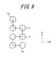
FIG. 9 is a cross sectional view explaining yet another example of the bead core for use in a Comparative Example pneumatic tire. -
FIG. 3 is a cross sectional view of one example of a bead core for use in a pneumatic tire of the present invention. - This bead core has a torus structure formed by winding a strand as a rubber-coated single bead wire 1 (around a bead portion) to be juxtaposed in two columns in the axial direction of the torus structure, as shown in
FIG. 3 . - Further, the strand is stacked in plural rows (three rows in the example of
FIG. 3 ) in the radial direction of the torus structure in the bead core. - Yet further, a winding-
start end 1s and a winding-terminal end 1e are situated on the outermost side in the radial direction of the respective columns in the bead core. - Such a bead core as described above can be manufactured by winding the strand or the
bead wire 1 from the outer side toward the inner side in the radial direction at one column and then from the inner side toward the outer side in the radial direction at the other column (see the arrow indicating the winding order inFIG. 3 ). - The number of rows in the radial direction in the one column in the axial direction may differ from the number of rows in the radial direction in the other column in the axial direction, as shown in
FIG. 6 andFIG. 7 , respectively. Such bead cores as shown inFIGS. 6 and7 can be each manufactured by winding the strand or thebead wire 1 from the outer side toward the inner side in the radial direction at one column and then from the inner side toward the outer side in the radial direction at the other column, as is the case with the example shown inFIG. 3 (see the arrows indicating the winding orders inFIG. 6 andFIG. 7 ). -
FIG. 4 is a view showing a vicinity of an end portion of thebead wire 1 of the bead core shown inFIG. 3 . - It is essentially important in the bead core for use in a tire of the present invention that at least one of an
interval 1t between the winding-start end 1s and an inner peripheral layer adjacent to the winding-start end 1s of the bead wire and an interval between the winding-terminal end 1e and an inner peripheral layer adjacent to the winding-terminal end 1e of the bead wire is larger than any other intervals between two adjacent bead wires (i.e. any other interlayer intervals between one bead wire layer and another bead wire layer on the inner side in the radial direction than the radiallyoutermost interval 1t of the bead core), as shown inFIG. 4 . - An effect of the present invention, caused by the aforementioned structures, will be described hereinafter.
- First, according to the present invention, since at least one of an interval between the winding-start end and an inner peripheral layer adjacent to the winding-start end of the bead wire and an interval between the winding-terminal end and an inner peripheral layer adjacent to the winding-terminal end of the bead wire is relatively large, it is possible to suppress an increase in tensile force between the two adjacent bead wires when the increase occurs due to shearing deformation of rubber described above, thereby
- enhancing fracture strength of the bead core.
- Further, according to the present invention, it is possible to mitigate concentration of stresses at the winding-start end and the winding-terminal end to enhance fracture strength of the bead core because the winding-start end and the winding-terminal end are each situated on the outermost side in the radial direction of the bead core.
- Yet further, according to the present invention, bead-expansion force of the bead core also enhances because neither the winding-start end nor the winding-terminal end are situated on the inner side in the radial direction.
- Yet further, according to the present invention, since the bead core has a torus structure constituted of only two columns of the strand juxtaposed in the axial direction of the torus structure and thus the bead core has a significantly narrowed width, it is possible to reduce tire weight by using the bead core in a bead portion of a tire.
- Yet further, in terms of a manufacturing aspect of the bead core, the winding-start end and the winding-terminal end can be each easily positioned on the outermost side in the radial direction by winding the strand from the outer side toward the inner side in the radial direction at one column and then from the inner side toward the outer side in the radial direction at the other column as described above because the bead core as the torus structure is constituted of two columns of the strand juxtaposed in the axial direction.
- In this connection, it is possible in manufacturing the bead core to prevent the winding-start end and the winding-terminal end thereof from being interfered by other bead wire layers, to enhance work efficiency and easily control an inter-wire distance between each of the winding-start end and the winding-terminal end and an inner peripheral bead wire layer adjacent thereto, because the winding-start end and the winding-terminal end are each situated on the outermost side in the radial direction of the bead core.
- The bead core for use in the tire of the present invention therefore has a merit of production easiness, as well.
- In the present invention, the interval between the winding-start end and an inner peripheral layer adjacent to the winding-start end, of the bead wire, is preferably larger than any other intervals between two adjacent bead wires of the bead core.
- The arrangement above is preferable because it can mitigate shearing deformation of rubber between the bead wires caused by force in the direction of pulling the winding-start end out in the circumferential direction
- Further, it is preferable that the interval between the winding-terminal end and an inner peripheral layer adjacent to the winding-terminal end of the bead wire, as well as the interval between the winding-start end and an inner peripheral layer adjacent to the winding-start end of the bead wire, is larger than any other intervals between two adjacent bead wires of the bead core.
- The arrangement above is preferable because it can suppress an increase in tensile force between adjacent bead wires at the respective end portions thereof when the increase occurs due to shearing deformation of rubber between each end portion and an inner peripheral layer adjacent thereto of the bead wire, thereby successfully enhancing fracture strength of the bead core.
- Yet further, in the present invention, the interval between the winding-start end and an inner peripheral layer adjacent to the winding-start end, of the bead wire, is larger than any other intervals between two adjacent bead wires of the bead core preferably in a range from the winding-start end to at least a position on the bead wire 5 mm away from the winding-start end along a circumference of the bead wire but not beyond a position on the bead wire away by one circumference from the winding-start end.
- In other words, a range in which the interval between the winding-start end and an inner peripheral layer adjacent to the winding-start end, of the bead wire, is larger than any other intervals between two adjacent bead wires of the bead core is set preferably from the winding-start end to at least a position on the bead wire 5 mm away from the winding-start end along a circumference of the bead wire but not beyond a position on the bead wire away by one circumference from the winding-start end.
- The arrangement above is preferable because: when the aforementioned range in which the interval between the winding-start end and an inner peripheral layer adjacent thereto is larger than any other intervals between two adjacent bead wires is situated on the bead wire less than 5 mm away from the winding-start end along a circumference of the bead wire, the shearing deformation of rubber described above cannot be sufficiently mitigated; and when the aforementioned range is situated on the bead wire away, by more than one circumference, from the winding-start end, an effect of mitigating shearing deformation of rubber reaches a plateau and no longer improves.
- In the present invention, a circumferential length of "one circumference" of the bead wire is defined, provided that a position It on the inner peripheral layer adjacent to the winding-
start end 1s of the bead wire corresponds to or faces the winding-start end 1s as shown inFIG. 4 , as a circumferential length measured from the winding-start end 1s to theposition 1t. - Similarly, in the present invention, the interval between the winding-terminal end and an inner peripheral layer adjacent to the winding-terminal end, of the bead wire, is larger than any other intervals between two adjacent bead wires of the bead core preferably in a range from the winding-terminal end to at least a position on the bead wire 5 mm away from the winding-terminal end along a circumference of the bead wire but not beyond a position on the bead wire away by one circumference from the winding-terminal end.
- In other words, a range in which the interval between the winding-terminal end and an inner peripheral layer adjacent to the winding-terminal end, of the bead wire, is larger than any other intervals between two adjacent bead wires of the bead core is set preferably from the winding-terminal end to at least a position on the bead wire 5 mm away from the winding-terminal end along a circumference of the bead wire but not beyond a position on the bead wire away by one circumference from the winding-terminal end.
- The arrangement above is preferable because: when the aforementioned range in which the interval between the winding-terminal end and an inner peripheral layer adjacent thereto is larger than any other intervals between two adjacent bead wires is situated on the bead wire less than 5 mm away from the winding-terminal end along a circumference of the bead wire, the shearing deformation of rubber described above cannot be sufficiently mitigated; and when the aforementioned range is situated on the bead wire away, by more than one circumference, from the winding-terminal end, an effect of mitigating shearing deformation of rubber reaches a plateau and no longer improves.
- In the present invention, a circumferential length of "one circumference" of the bead wire is defined, provided that a position on the inner peripheral layer adjacent to the winding-terminal end of the bead wire corresponds to or faces the winding-terminal end, as a circumferential length measured from the winding-terminal end to the position.
- Further, in the present invention, a distance between the centers of the two adjacent bead wires in the aforementioned range from the winding-start end to at least a position on the bead wire 5 mm away from the winding-start end along a circumference of the bead wire but not beyond a position on the bead wire away by one circumference from the winding-start end is preferably 1.2 to 5 times larger than a distance between the centers of the two adjacent bead wires at a position beyond said range.
- In other words, a distance between the centers of the two adjacent bead wires in the range in which the interval between the winding-start end and an inner peripheral layer adjacent thereto of the bead wire is larger than any other intervals between two adjacent bead wires of the bead core is preferably 1.2 to 5 times larger than a distance between the centers of the two adjacent bead wires at a position beyond said range.
- The arrangement above is preferable because: when a distance between the centers of the two adjacent bead wires in the aforementioned range is at least 1.2 times larger than a distance between the centers of the two adjacent bead wires at a position beyond said range, at least an effect at the minimum level required in the present invention can be ensured by a relatively small change in the bead core configuration; and when a distance between the centers of the two adjacent bead wires in the aforementioned range is not more than 5 times larger than a distance between the centers of the two adjacent bead wires at a position beyond said range, it is possible to suppress an adverse effect possibly caused on uniformity of the bead core by an unbalanced cross section of the bead core to the minimum, while sufficiently mitigating shearing deformation of rubber between the relevant bead wires.
- Similarly, in the present invention, a distance between the centers of the two adjacent bead wires in the aforementioned range from the winding-terminal end to at least a position on the bead wire 5 mm away from the winding-terminal end along a circumference of the bead wire but not beyond a position on the bead wire away by one circumference from the winding-terminal end is preferably 1.2 to 5 times larger than a distance between the centers of the two adjacent bead wires at a position beyond said range.
- In other words, a distance between the centers of the two adjacent bead wires in the range in which the interval between the winding-terminal end and an inner peripheral layer adjacent thereto of the bead wire is larger than any other intervals between two adjacent bead wires of the bead core is preferably 1.2 to 5 times larger than a distance between the centers of the two adjacent bead wires at a position beyond said range.
- The arrangement above is preferable because: when a distance between the centers of the two adjacent bead wires in the aforementioned range is at least 1.2 times larger than a distance between the centers of the two adjacent bead wires at a position beyond said range, at least an effect at the minimum level required in the present invention can be ensured by a relatively small change in the bead core configuration; and when a distance between the centers of the two adjacent bead wires in the aforementioned range is not more than 5 times larger than a distance between the centers of the two adjacent bead wires at a position beyond said range, it is possible to suppress an adverse effect possibly caused on uniformity of the bead core by an unbalanced cross section of the bead core to the minimum, while sufficiently mitigating shearing deformation of rubber between the relevant bead wires.
- In order to confirm an effect of the present invention, each of pneumatic test tires for Examples 1 to 3 was prepared by: manufacturing a corresponding bead core where two columns of a bead wire is juxtaposed in the axial direction, a winding-start end and a winding-terminal end of the bead wire are each situated on the outermost side in the radial direction, and at least one of an interval between the winding-start end and an inner peripheral layer adjacent to the winding-start end of the bead wire and an interval between the winding-terminal end and an inner peripheral layer adjacent to the winding-terminal end of the bead wire is larger than any other intervals between two adjacent bead wires of the bead core; and embedding the bead core in a bead portion of a tire.
- Further, a pneumatic test tire for Comparative Example 1 was prepared by: manufacturing a corresponding bead core where two columns of a bead wire is juxtaposed in the axial direction and a winding-start end and a winding-terminal end of the bead wire are situated on the innermost side and the outermost side in the radial direction, respectively, as shown in
FIG. 5 ; and embedding the bead core in a bead portion of a tire. - Yet further, a pneumatic test tire for Comparative Example 2 was prepared by: manufacturing a corresponding bead core where two columns of a bead wire is juxtaposed in the axial direction, a winding-start end and a winding-terminal end of the bead wire are each situated on the outermost side in the radial direction, but an interval between the winding-start end and an inner peripheral layer adjacent thereto of the bead wire and an interval between the winding-terminal end and an inner peripheral layer adjacent thereto of the bead wire is each equal to other intervals between two adjacent bead wires of the bead core; and embedding the bead core in a bead portion of a tire.
- Table 1 shows details of the characteristics of the respective test tires.
- In Examples 1 and 2, a range in which the interval between the winding-start end and an inner peripheral layer adjacent thereto of the bead wire is larger than any other intervals between two adjacent bead wires of the bead core was set from the winding-start end to a position on the bead wire 5 mm away from the winding-start end along a circumference of the bead wire; and a range in which the interval between the winding-terminal end and an inner peripheral layer adj acent thereto of the bead wire is larger than any other intervals between two adjacent bead wires of the bead core was set from the winding-terminal end to a position on the bead wire 5 mm away from the winding-terminal end along a circumference of the bead wire.
- In Examples 1 to 3, a circumferential length of "one circumference" of the bead wire is 1045 mm on each of the winding-start end side and the winding-terminal end side.
Table 1 Figure Number of columns in the axial direction Number of rows in the radial direction Radial position of winding-start end Radial position of winding-terminal end Interval between winding-start end and inner peripheral layer adjacent thereto Interval between winding-terminal end and inner peripheral layer adjacent thereto Example 1 Fig. 3 2 3 Outermost side Outermost side Larger than intervals between other adjacent bead wires Larger than intervals between other adjacent bead wires Example 2 Fig. 3 2 3 Outermost side Outermost side Larger than intervals between other adjacent bead wires Equal to intervals between other adjacent bead wires Example 3 Fig. 3 2 3 Outermost side Outermost side Equal to intervals between other adjacent bead wires Larger than intervals between other adjacent bead wires Comp. Example 1 Fig. 5 2 3 Innermost side Outermost side Equal to intervals between other adjacent bead wires Equal to intervals between other adjacent bead wires Comp. Example 2 Fig. 3 2 3 Outermost side Outermost side Equal to intervals between other adjacent bead wires Equal to intervals between other adjacent bead wires - Following tests were carried out for each of the aforementioned test tires.
- Fracture strength of the test tire (tire size: 155/65R13) was evaluated by a hydraulic fracture test including the steps of assembling the tire with a prescribed rim having rim size: 13 x 4.5J, injecting water into the tire, and measuring hydraulic pressure when the bead core is fractured.
- The evaluation results are expressed as index values relative to the reference value "100" for Comparative Example 1. The larger value represents the higher fracture strength of the sample.
- Bead-expansion force of the test tire was evaluated by: disposing a bead portion of one side of the pneumatic tire to be tested on an eight-divided rim block of a bead-expansion force tester manufactured by Hoffmann Corporation; measuring a magnitude of change in the bead portion of the tire when the bead portion is expanded toward the outer side in the radial direction; and converting the magnitude of change in the bead portion thus measured into an index value representing bead-expansion force of the tire, for evaluation.
- The evaluation results are expressed as index values relative to the reference value "100" for the bead-expansion force of Comparative Example 1. The larger value represents the higher bead-expansion force of the sample.
- The evaluation results of these two tests are shown in Table 2.
Table 2 Bead-expansion force Fracture strength Example 1 130 105 Example 2 130 103 Example 3 130 103 Comp. Example 1 100 100 Comp. Example 2 130 100 - It is understood from Table 2 that the test tires of Examples 1 to 3 are unanimously more excellent in both bead-expansion force and fracture strength than the test tire of Comparative Example 1 and unanimously more excellent in fracture strength than the test tire of Comparative Example 2.
- Next, a test tire for Conventional Example was prepared by embedding the conventional bead core shown in
FIG. 1 in a bead portion of a tire. Tire weight was measured for each of the test tires of Example 1 and Conventional Example. The evaluation results expressed as index values relative to the reference value "100" for the tire weight of Conventional Example are shown in Table 3 below. The smaller value represents the more reduced tire weight of the sample.Table 3 Tire weight Example 1 98 Conventional Example 100 - It is understood from Table 3 that the test tire of Example 1, having narrower width of the bead core, exhibits more reduced tire weight than the test tire of Conventional Example.
- Next, each of test tires for Examples 4 to 13 was prepared by changing either a ratio of a distance between the centers of the two adjacent bead wires at the winding-start end, with respect to a distance between the centers of other two adjacent bead wires, of the bead core ("Ratio of between-center distance on the winding-start end side" in Table 4) or a ratio of a distance between the centers of the two adjacent bead wires at the winding-terminal end, with respect to the distance between the centers of other two adjacent bead wires, of the bead core ("Ratio of between-center distance on the winding-terminal end side" in Table 4). Each of these test tires was subjected to a test for evaluating fracture strength in a manner similar to the foregoing Examples and Comparative Examples. Details of the characteristics and evaluation results of the test tires for Examples 4 to 13 are shown in Table 4.
- The evaluation results are expressed in
FIG. 4 as index values relative to the reference value "100" for Comparative Example 1. The larger value represents the higher fracture strength of the sample. - Each of the test tires of Examples 4 to 13 is substantially the same as the tire of Example 1, except that the former has the characteristics shown in Table 4.
Table 4 Ratio of between-center distance on the winding-start end side Ratio of between-center distance on the winding-terminal end side Fracture strength Example 4 1.1 1 101 Example 5 1.2 1 102 Example 6 3 1 103 Example 7 5 1 104 Example 8 6 1 104 Example 9 1 1.1 101 Example 10 1 1.2 102 Example 11 1 3 103 Example 12 1 5 104 Example 13 1 6 104 - It is understood from Table 4 that the test tires of Examples 5 to 7 and Examples 10 to 12, each having an optimum ratio of a distance between the centers of the two adjacent bead wires at the winding-start/terminal end with respect to the distance between the centers of other two adjacent bead wires, unanimously exhibit better fracture strength than the test tire of Conventional Example 1.
- Further, it is understood from comparison of Example 7 with Example 8 and comparison of Example 12 with Example 13, respectively, that setting either "Ratio of between-center distance on the winding-start end side" or "Ratio of between-center distance on the winding-terminal end side" to be 5 suffices to satisfactorily improve fracture strength of the bead core. Accordingly, setting either "Ratio of between-center distance on the winding-start end side" or "Ratio of between-center distance on the winding-terminal end side" to be around but not larger than 5 will effectively suppress an adverse effect on uniformity of the bead core, while satisfactorily improving fracture strength of the bead core.
-
- 1
- Bead wire
- 1s
- Winding-start end
- 1e
- Winding-terminal end
Claims (7)
- A pneumatic tire having a bead core embedded in a bead portion of the tire, the bead core being constituted of a strand as a rubber-coated single bead wire wound around the bead portion to be juxtaposed in plural columns in the axial direction and stacked in plural rows in the radial direction to form a torus structure, characterized in that:the bead core as the torus structure is constituted of two columns of the bead wire juxtaposed in the axial direction;a winding-start end and a winding-terminal end of the bead wire are situated at the outermost rows in the radial direction of the corresponding columns thereof, respectively; andat least one of an interval between the winding-start end and an inner peripheral layer adjacent to the winding-start end of the bead wire and an interval between the winding-terminal end and an inner peripheral layer adjacent to the winding-terminal end of the bead wire is larger than any other intervals between two adjacent bead wires of the bead core.
- The pneumatic tire of claim 1, wherein the interval between the winding-start end and an inner peripheral layer adjacent to the winding-start end, of the bead wire, is larger than any other intervals between two adjacent bead wires of the bead core.
- The pneumatic tire of claim 1 or 2, wherein the interval between the winding-start end and an inner peripheral layer adjacent to the winding-start end of the bead wire and the interval between the winding-terminal end and an inner peripheral layer adjacent to the winding-terminal end of the bead wire are each larger than any other intervals between two adjacent bead wires of the bead core.
- The pneumatic tire of claim 2 or 3, wherein the interval between the winding-start end and an inner peripheral layer adjacent to the winding-start end, of the bead wire, is larger than any other intervals between two adjacent bead wires of the bead core in a range from the winding-start end to at least a position on the bead wire 5 mm away from the winding-start end along a circumference of the bead wire but not beyond a position on the bead wire away by one circumference from the winding-start end.
- The pneumatic tire of claim 3, wherein the interval between the winding-terminal end and an inner peripheral layer adjacent to the winding-terminal end, of the bead wire, is larger than any other intervals between two adjacent bead wires of the bead core in a range from the winding-terminal end to at least a position on the bead wire 5 mm away from the winding-terminal end along a circumference of the bead wire but not beyond a position on the bead wire away by one circumference from the winding-terminal end.
- The pneumatic tire of claim 4, wherein a distance between the centers of the two adjacent bead wires in said range in which the interval between the winding-start end and an inner peripheral layer adjacent to the winding-start end, of the bead wire, is larger than any other intervals between two adjacent bead wires of the bead core is 1.2 to 5 times larger than a distance between the centers of the two adjacent bead wires at a position beyond said range.
- The pneumatic tire of claim 5, wherein a distance between the centers of the two adjacent bead wires in said range in which the interval between the winding-terminal end and an inner peripheral layer adjacent to the winding-terminal end, of the bead wire, is larger than any other intervals between two adjacent bead wires of the bead core is 1.2 to 5 times larger than a distance between the centers of the two adjacent bead wires at a position beyond said range.
Applications Claiming Priority (2)
| Application Number | Priority Date | Filing Date | Title |
|---|---|---|---|
| JP2011136368 | 2011-06-20 | ||
| PCT/JP2012/004008 WO2012176447A1 (en) | 2011-06-20 | 2012-06-20 | Pneumatic tire |
Publications (3)
| Publication Number | Publication Date |
|---|---|
| EP2722200A1 true EP2722200A1 (en) | 2014-04-23 |
| EP2722200A4 EP2722200A4 (en) | 2015-07-01 |
| EP2722200B1 EP2722200B1 (en) | 2018-05-16 |
Family
ID=47422304
Family Applications (1)
| Application Number | Title | Priority Date | Filing Date |
|---|---|---|---|
| EP12802724.0A Not-in-force EP2722200B1 (en) | 2011-06-20 | 2012-06-20 | Pneumatic tire |
Country Status (5)
| Country | Link |
|---|---|
| US (1) | US20140124118A1 (en) |
| EP (1) | EP2722200B1 (en) |
| JP (1) | JPWO2012176447A1 (en) |
| CN (1) | CN103608195A (en) |
| WO (1) | WO2012176447A1 (en) |
Families Citing this family (1)
| Publication number | Priority date | Publication date | Assignee | Title |
|---|---|---|---|---|
| JP2020069690A (en) * | 2018-10-30 | 2020-05-07 | Toyo Tire株式会社 | Bead member manufacturing method, bead member and pneumatic tire |
Family Cites Families (18)
| Publication number | Priority date | Publication date | Assignee | Title |
|---|---|---|---|---|
| DE3613100A1 (en) * | 1986-04-18 | 1987-10-29 | Continental Gummi Werke Ag | Core ring for the beads of pneumatic tyres |
| JPH0616018A (en) * | 1992-06-30 | 1994-01-25 | Bridgestone Corp | Pneumatic tire |
| JPH06143914A (en) * | 1992-11-02 | 1994-05-24 | Bridgestone Corp | Pneumatic radial tire |
| JPH08290703A (en) * | 1995-04-21 | 1996-11-05 | Yokohama Rubber Co Ltd:The | Pneumatic bias tire |
| JP4382177B2 (en) * | 1998-09-01 | 2009-12-09 | 株式会社ブリヂストン | Pneumatic radial tire |
| JP2001097010A (en) * | 1999-09-30 | 2001-04-10 | Bridgestone Corp | Pneumatic tire |
| EP1103390A1 (en) * | 1999-11-23 | 2001-05-30 | Bekaert Naamloze Vennootschap | Steel wire bead for tyres |
| ATE298674T1 (en) * | 1999-12-03 | 2005-07-15 | Michelin Soc Tech | BEAD FOR FLAT TIRES |
| JP2002254909A (en) * | 2001-02-28 | 2002-09-11 | Yokohama Rubber Co Ltd:The | Pneumatic tire |
| JP2003025815A (en) | 2001-07-10 | 2003-01-29 | Bridgestone Corp | Pneumatic bias tire |
| JP2003118323A (en) * | 2001-10-16 | 2003-04-23 | Sumitomo Rubber Ind Ltd | Pneumatic tire |
| JP2005028944A (en) * | 2003-07-09 | 2005-02-03 | Yokohama Rubber Co Ltd:The | Bead for tire |
| JP2009051451A (en) * | 2007-08-29 | 2009-03-12 | Yokohama Rubber Co Ltd:The | Pneumatic bias tire |
| DE102008004886A1 (en) * | 2008-01-17 | 2009-07-23 | Continental Aktiengesellschaft | Vehicle tires |
| KR20100006627A (en) * | 2008-07-10 | 2010-01-21 | 한국타이어 주식회사 | Pneumatic vehicle tire |
| DE102008049314A1 (en) * | 2008-09-29 | 2010-04-01 | Continental Reifen Deutschland Gmbh | Vehicle tires |
| DE102008049315A1 (en) * | 2008-09-29 | 2010-04-01 | Continental Reifen Deutschland Gmbh | Vehicle tires |
| JP5351675B2 (en) * | 2009-09-10 | 2013-11-27 | 不二精工株式会社 | Bead core for pneumatic tire and pneumatic tire using the bead core |
-
2012
- 2012-06-20 EP EP12802724.0A patent/EP2722200B1/en not_active Not-in-force
- 2012-06-20 JP JP2013521458A patent/JPWO2012176447A1/en active Pending
- 2012-06-20 CN CN201280030453.8A patent/CN103608195A/en active Pending
- 2012-06-20 US US14/124,842 patent/US20140124118A1/en not_active Abandoned
- 2012-06-20 WO PCT/JP2012/004008 patent/WO2012176447A1/en not_active Ceased
Also Published As
| Publication number | Publication date |
|---|---|
| EP2722200A4 (en) | 2015-07-01 |
| EP2722200B1 (en) | 2018-05-16 |
| JPWO2012176447A1 (en) | 2015-02-23 |
| US20140124118A1 (en) | 2014-05-08 |
| CN103608195A (en) | 2014-02-26 |
| WO2012176447A1 (en) | 2012-12-27 |
Similar Documents
| Publication | Publication Date | Title |
|---|---|---|
| EP3027805B1 (en) | High elongation steel cord and pneumatic tire comprising said cord | |
| US20150159325A1 (en) | Method of manufacturing a two-layer multistrand metal cord | |
| US20150136295A1 (en) | Two-layer multi-strand metal cable | |
| US10906353B2 (en) | Steel cord for reinforcing rubber article | |
| EP3000624B1 (en) | Pneumatic tire | |
| EP3196354B2 (en) | Steel cord for reinforcing rubber article | |
| EP2236663A1 (en) | Steel cord for tire and pneumatic tire employing it | |
| EP3202977B1 (en) | Steel cord for reinforcing rubber article, and pneumatic tire using same | |
| EP3196355B1 (en) | Steel cord for reinforcing rubber article | |
| CN102282311A (en) | Steel cords for reinforcing rubber products and pneumatic tires | |
| US20170028789A1 (en) | Tire | |
| EP2722200B1 (en) | Pneumatic tire | |
| EP2248683A1 (en) | Pneumatic tire for heavy loads | |
| EA019624B1 (en) | Tyre for heavy vehicles having a crown reinforcement comprising a complex strip | |
| JP5425515B2 (en) | Pneumatic tire | |
| JPWO2018105419A1 (en) | Heavy load tire and method for manufacturing heavy load tire | |
| JP2006283198A (en) | Steel cord and tire | |
| JP4903035B2 (en) | Radial tire | |
| EP2319710A1 (en) | Pneumatic radial tire | |
| JP5678558B2 (en) | Pneumatic tire | |
| JP2005041392A (en) | Tire excellent in bead section durability | |
| JP2011143823A (en) | Pneumatic radial tire | |
| JP2011032596A (en) | Steel cord for reinforcing rubber article and tire | |
| JP2009293149A (en) | Steel cord for reinforcing rubber article, and pneumatic radial tire using the same | |
| JP2008062739A (en) | Heavy load pneumatic bias tire |
Legal Events
| Date | Code | Title | Description |
|---|---|---|---|
| PUAI | Public reference made under article 153(3) epc to a published international application that has entered the european phase |
Free format text: ORIGINAL CODE: 0009012 |
|
| 17P | Request for examination filed |
Effective date: 20131205 |
|
| AK | Designated contracting states |
Kind code of ref document: A1 Designated state(s): AL AT BE BG CH CY CZ DE DK EE ES FI FR GB GR HR HU IE IS IT LI LT LU LV MC MK MT NL NO PL PT RO RS SE SI SK SM TR |
|
| DAX | Request for extension of the european patent (deleted) | ||
| RA4 | Supplementary search report drawn up and despatched (corrected) |
Effective date: 20150603 |
|
| RIC1 | Information provided on ipc code assigned before grant |
Ipc: B60C 15/04 20060101AFI20150528BHEP Ipc: D07B 1/06 20060101ALI20150528BHEP |
|
| GRAP | Despatch of communication of intention to grant a patent |
Free format text: ORIGINAL CODE: EPIDOSNIGR1 |
|
| INTG | Intention to grant announced |
Effective date: 20171127 |
|
| GRAS | Grant fee paid |
Free format text: ORIGINAL CODE: EPIDOSNIGR3 |
|
| GRAA | (expected) grant |
Free format text: ORIGINAL CODE: 0009210 |
|
| AK | Designated contracting states |
Kind code of ref document: B1 Designated state(s): AL AT BE BG CH CY CZ DE DK EE ES FI FR GB GR HR HU IE IS IT LI LT LU LV MC MK MT NL NO PL PT RO RS SE SI SK SM TR |
|
| REG | Reference to a national code |
Ref country code: GB Ref legal event code: FG4D |
|
| REG | Reference to a national code |
Ref country code: CH Ref legal event code: EP |
|
| REG | Reference to a national code |
Ref country code: IE Ref legal event code: FG4D |
|
| REG | Reference to a national code |
Ref country code: DE Ref legal event code: R096 Ref document number: 602012046439 Country of ref document: DE |
|
| REG | Reference to a national code |
Ref country code: AT Ref legal event code: REF Ref document number: 999201 Country of ref document: AT Kind code of ref document: T Effective date: 20180615 |
|
| REG | Reference to a national code |
Ref country code: FR Ref legal event code: PLFP Year of fee payment: 7 |
|
| REG | Reference to a national code |
Ref country code: NL Ref legal event code: MP Effective date: 20180516 |
|
| REG | Reference to a national code |
Ref country code: LT Ref legal event code: MG4D |
|
| PG25 | Lapsed in a contracting state [announced via postgrant information from national office to epo] |
Ref country code: NO Free format text: LAPSE BECAUSE OF FAILURE TO SUBMIT A TRANSLATION OF THE DESCRIPTION OR TO PAY THE FEE WITHIN THE PRESCRIBED TIME-LIMIT Effective date: 20180816 Ref country code: LT Free format text: LAPSE BECAUSE OF FAILURE TO SUBMIT A TRANSLATION OF THE DESCRIPTION OR TO PAY THE FEE WITHIN THE PRESCRIBED TIME-LIMIT Effective date: 20180516 Ref country code: ES Free format text: LAPSE BECAUSE OF FAILURE TO SUBMIT A TRANSLATION OF THE DESCRIPTION OR TO PAY THE FEE WITHIN THE PRESCRIBED TIME-LIMIT Effective date: 20180516 Ref country code: SE Free format text: LAPSE BECAUSE OF FAILURE TO SUBMIT A TRANSLATION OF THE DESCRIPTION OR TO PAY THE FEE WITHIN THE PRESCRIBED TIME-LIMIT Effective date: 20180516 Ref country code: BG Free format text: LAPSE BECAUSE OF FAILURE TO SUBMIT A TRANSLATION OF THE DESCRIPTION OR TO PAY THE FEE WITHIN THE PRESCRIBED TIME-LIMIT Effective date: 20180816 Ref country code: FI Free format text: LAPSE BECAUSE OF FAILURE TO SUBMIT A TRANSLATION OF THE DESCRIPTION OR TO PAY THE FEE WITHIN THE PRESCRIBED TIME-LIMIT Effective date: 20180516 |
|
| PG25 | Lapsed in a contracting state [announced via postgrant information from national office to epo] |
Ref country code: LV Free format text: LAPSE BECAUSE OF FAILURE TO SUBMIT A TRANSLATION OF THE DESCRIPTION OR TO PAY THE FEE WITHIN THE PRESCRIBED TIME-LIMIT Effective date: 20180516 Ref country code: RS Free format text: LAPSE BECAUSE OF FAILURE TO SUBMIT A TRANSLATION OF THE DESCRIPTION OR TO PAY THE FEE WITHIN THE PRESCRIBED TIME-LIMIT Effective date: 20180516 Ref country code: GR Free format text: LAPSE BECAUSE OF FAILURE TO SUBMIT A TRANSLATION OF THE DESCRIPTION OR TO PAY THE FEE WITHIN THE PRESCRIBED TIME-LIMIT Effective date: 20180817 Ref country code: HR Free format text: LAPSE BECAUSE OF FAILURE TO SUBMIT A TRANSLATION OF THE DESCRIPTION OR TO PAY THE FEE WITHIN THE PRESCRIBED TIME-LIMIT Effective date: 20180516 Ref country code: NL Free format text: LAPSE BECAUSE OF FAILURE TO SUBMIT A TRANSLATION OF THE DESCRIPTION OR TO PAY THE FEE WITHIN THE PRESCRIBED TIME-LIMIT Effective date: 20180516 |
|
| REG | Reference to a national code |
Ref country code: AT Ref legal event code: MK05 Ref document number: 999201 Country of ref document: AT Kind code of ref document: T Effective date: 20180516 |
|
| PG25 | Lapsed in a contracting state [announced via postgrant information from national office to epo] |
Ref country code: AT Free format text: LAPSE BECAUSE OF FAILURE TO SUBMIT A TRANSLATION OF THE DESCRIPTION OR TO PAY THE FEE WITHIN THE PRESCRIBED TIME-LIMIT Effective date: 20180516 Ref country code: DK Free format text: LAPSE BECAUSE OF FAILURE TO SUBMIT A TRANSLATION OF THE DESCRIPTION OR TO PAY THE FEE WITHIN THE PRESCRIBED TIME-LIMIT Effective date: 20180516 Ref country code: EE Free format text: LAPSE BECAUSE OF FAILURE TO SUBMIT A TRANSLATION OF THE DESCRIPTION OR TO PAY THE FEE WITHIN THE PRESCRIBED TIME-LIMIT Effective date: 20180516 Ref country code: PL Free format text: LAPSE BECAUSE OF FAILURE TO SUBMIT A TRANSLATION OF THE DESCRIPTION OR TO PAY THE FEE WITHIN THE PRESCRIBED TIME-LIMIT Effective date: 20180516 Ref country code: SK Free format text: LAPSE BECAUSE OF FAILURE TO SUBMIT A TRANSLATION OF THE DESCRIPTION OR TO PAY THE FEE WITHIN THE PRESCRIBED TIME-LIMIT Effective date: 20180516 Ref country code: CZ Free format text: LAPSE BECAUSE OF FAILURE TO SUBMIT A TRANSLATION OF THE DESCRIPTION OR TO PAY THE FEE WITHIN THE PRESCRIBED TIME-LIMIT Effective date: 20180516 Ref country code: RO Free format text: LAPSE BECAUSE OF FAILURE TO SUBMIT A TRANSLATION OF THE DESCRIPTION OR TO PAY THE FEE WITHIN THE PRESCRIBED TIME-LIMIT Effective date: 20180516 |
|
| REG | Reference to a national code |
Ref country code: CH Ref legal event code: PL |
|
| REG | Reference to a national code |
Ref country code: DE Ref legal event code: R097 Ref document number: 602012046439 Country of ref document: DE |
|
| PG25 | Lapsed in a contracting state [announced via postgrant information from national office to epo] |
Ref country code: IT Free format text: LAPSE BECAUSE OF FAILURE TO SUBMIT A TRANSLATION OF THE DESCRIPTION OR TO PAY THE FEE WITHIN THE PRESCRIBED TIME-LIMIT Effective date: 20180516 Ref country code: SM Free format text: LAPSE BECAUSE OF FAILURE TO SUBMIT A TRANSLATION OF THE DESCRIPTION OR TO PAY THE FEE WITHIN THE PRESCRIBED TIME-LIMIT Effective date: 20180516 |
|
| REG | Reference to a national code |
Ref country code: BE Ref legal event code: MM Effective date: 20180630 |
|
| REG | Reference to a national code |
Ref country code: IE Ref legal event code: MM4A |
|
| PLBE | No opposition filed within time limit |
Free format text: ORIGINAL CODE: 0009261 |
|
| STAA | Information on the status of an ep patent application or granted ep patent |
Free format text: STATUS: NO OPPOSITION FILED WITHIN TIME LIMIT |
|
| PG25 | Lapsed in a contracting state [announced via postgrant information from national office to epo] |
Ref country code: LU Free format text: LAPSE BECAUSE OF NON-PAYMENT OF DUE FEES Effective date: 20180620 Ref country code: MC Free format text: LAPSE BECAUSE OF FAILURE TO SUBMIT A TRANSLATION OF THE DESCRIPTION OR TO PAY THE FEE WITHIN THE PRESCRIBED TIME-LIMIT Effective date: 20180516 |
|
| 26N | No opposition filed |
Effective date: 20190219 |
|
| GBPC | Gb: european patent ceased through non-payment of renewal fee |
Effective date: 20180816 |
|
| PG25 | Lapsed in a contracting state [announced via postgrant information from national office to epo] |
Ref country code: IE Free format text: LAPSE BECAUSE OF NON-PAYMENT OF DUE FEES Effective date: 20180620 Ref country code: CH Free format text: LAPSE BECAUSE OF NON-PAYMENT OF DUE FEES Effective date: 20180630 Ref country code: LI Free format text: LAPSE BECAUSE OF NON-PAYMENT OF DUE FEES Effective date: 20180630 |
|
| PG25 | Lapsed in a contracting state [announced via postgrant information from national office to epo] |
Ref country code: SI Free format text: LAPSE BECAUSE OF FAILURE TO SUBMIT A TRANSLATION OF THE DESCRIPTION OR TO PAY THE FEE WITHIN THE PRESCRIBED TIME-LIMIT Effective date: 20180516 Ref country code: BE Free format text: LAPSE BECAUSE OF NON-PAYMENT OF DUE FEES Effective date: 20180630 |
|
| PG25 | Lapsed in a contracting state [announced via postgrant information from national office to epo] |
Ref country code: GB Free format text: LAPSE BECAUSE OF NON-PAYMENT OF DUE FEES Effective date: 20180816 |
|
| PG25 | Lapsed in a contracting state [announced via postgrant information from national office to epo] |
Ref country code: AL Free format text: LAPSE BECAUSE OF FAILURE TO SUBMIT A TRANSLATION OF THE DESCRIPTION OR TO PAY THE FEE WITHIN THE PRESCRIBED TIME-LIMIT Effective date: 20180516 |
|
| PG25 | Lapsed in a contracting state [announced via postgrant information from national office to epo] |
Ref country code: MT Free format text: LAPSE BECAUSE OF NON-PAYMENT OF DUE FEES Effective date: 20180620 |
|
| PG25 | Lapsed in a contracting state [announced via postgrant information from national office to epo] |
Ref country code: TR Free format text: LAPSE BECAUSE OF FAILURE TO SUBMIT A TRANSLATION OF THE DESCRIPTION OR TO PAY THE FEE WITHIN THE PRESCRIBED TIME-LIMIT Effective date: 20180516 |
|
| PG25 | Lapsed in a contracting state [announced via postgrant information from national office to epo] |
Ref country code: PT Free format text: LAPSE BECAUSE OF FAILURE TO SUBMIT A TRANSLATION OF THE DESCRIPTION OR TO PAY THE FEE WITHIN THE PRESCRIBED TIME-LIMIT Effective date: 20180516 Ref country code: HU Free format text: LAPSE BECAUSE OF FAILURE TO SUBMIT A TRANSLATION OF THE DESCRIPTION OR TO PAY THE FEE WITHIN THE PRESCRIBED TIME-LIMIT; INVALID AB INITIO Effective date: 20120620 |
|
| PG25 | Lapsed in a contracting state [announced via postgrant information from national office to epo] |
Ref country code: MK Free format text: LAPSE BECAUSE OF NON-PAYMENT OF DUE FEES Effective date: 20180516 Ref country code: CY Free format text: LAPSE BECAUSE OF FAILURE TO SUBMIT A TRANSLATION OF THE DESCRIPTION OR TO PAY THE FEE WITHIN THE PRESCRIBED TIME-LIMIT Effective date: 20180516 |
|
| PG25 | Lapsed in a contracting state [announced via postgrant information from national office to epo] |
Ref country code: IS Free format text: LAPSE BECAUSE OF FAILURE TO SUBMIT A TRANSLATION OF THE DESCRIPTION OR TO PAY THE FEE WITHIN THE PRESCRIBED TIME-LIMIT Effective date: 20180916 |
|
| PGFP | Annual fee paid to national office [announced via postgrant information from national office to epo] |
Ref country code: DE Payment date: 20200618 Year of fee payment: 9 Ref country code: FR Payment date: 20200619 Year of fee payment: 9 |
|
| REG | Reference to a national code |
Ref country code: DE Ref legal event code: R119 Ref document number: 602012046439 Country of ref document: DE |
|
| PG25 | Lapsed in a contracting state [announced via postgrant information from national office to epo] |
Ref country code: DE Free format text: LAPSE BECAUSE OF NON-PAYMENT OF DUE FEES Effective date: 20220101 |
|
| PG25 | Lapsed in a contracting state [announced via postgrant information from national office to epo] |
Ref country code: FR Free format text: LAPSE BECAUSE OF NON-PAYMENT OF DUE FEES Effective date: 20210630 |