EP2722147A1 - Method for manufacturing fiber-reinforced plastic - Google Patents
Method for manufacturing fiber-reinforced plastic Download PDFInfo
- Publication number
- EP2722147A1 EP2722147A1 EP12800101.3A EP12800101A EP2722147A1 EP 2722147 A1 EP2722147 A1 EP 2722147A1 EP 12800101 A EP12800101 A EP 12800101A EP 2722147 A1 EP2722147 A1 EP 2722147A1
- Authority
- EP
- European Patent Office
- Prior art keywords
- base material
- mold
- fiber
- reinforced plastic
- manufacturing
- Prior art date
- Legal status (The legal status is an assumption and is not a legal conclusion. Google has not performed a legal analysis and makes no representation as to the accuracy of the status listed.)
- Withdrawn
Links
- 238000000034 method Methods 0.000 title claims abstract description 50
- 229920002430 Fibre-reinforced plastic Polymers 0.000 title claims abstract description 49
- 239000011151 fibre-reinforced plastic Substances 0.000 title claims abstract description 49
- 238000004519 manufacturing process Methods 0.000 title claims abstract description 40
- 239000000463 material Substances 0.000 claims abstract description 124
- 239000012783 reinforcing fiber Substances 0.000 claims abstract description 108
- 229920005992 thermoplastic resin Polymers 0.000 claims abstract description 75
- 239000000835 fiber Substances 0.000 claims description 52
- 229920005989 resin Polymers 0.000 claims description 52
- 239000011347 resin Substances 0.000 claims description 52
- 229920000049 Carbon (fiber) Polymers 0.000 claims description 47
- 239000004917 carbon fiber Substances 0.000 claims description 47
- 238000009960 carding Methods 0.000 claims description 21
- 230000006835 compression Effects 0.000 claims description 15
- 238000007906 compression Methods 0.000 claims description 15
- 238000000465 moulding Methods 0.000 claims description 14
- 238000000748 compression moulding Methods 0.000 claims description 4
- 229920001643 poly(ether ketone) Polymers 0.000 claims description 3
- 239000004952 Polyamide Substances 0.000 claims description 2
- 239000004697 Polyetherimide Substances 0.000 claims description 2
- 239000004734 Polyphenylene sulfide Substances 0.000 claims description 2
- 229920002647 polyamide Polymers 0.000 claims description 2
- 239000004417 polycarbonate Substances 0.000 claims description 2
- 229920000515 polycarbonate Polymers 0.000 claims description 2
- 229920000728 polyester Polymers 0.000 claims description 2
- 229920001601 polyetherimide Polymers 0.000 claims description 2
- 229920000098 polyolefin Polymers 0.000 claims description 2
- 229920000069 polyphenylene sulfide Polymers 0.000 claims description 2
- 239000011159 matrix material Substances 0.000 description 15
- 238000002347 injection Methods 0.000 description 12
- 239000007924 injection Substances 0.000 description 12
- VNWKTOKETHGBQD-UHFFFAOYSA-N methane Chemical compound C VNWKTOKETHGBQD-UHFFFAOYSA-N 0.000 description 12
- 238000003825 pressing Methods 0.000 description 9
- 239000004918 carbon fiber reinforced polymer Substances 0.000 description 8
- 230000015572 biosynthetic process Effects 0.000 description 7
- 238000005470 impregnation Methods 0.000 description 6
- -1 polyethylene Polymers 0.000 description 4
- 230000000694 effects Effects 0.000 description 3
- 238000002844 melting Methods 0.000 description 3
- 230000008018 melting Effects 0.000 description 3
- 238000002156 mixing Methods 0.000 description 3
- 229920001187 thermosetting polymer Polymers 0.000 description 3
- 229920003235 aromatic polyamide Polymers 0.000 description 2
- 239000011230 binding agent Substances 0.000 description 2
- 238000010586 diagram Methods 0.000 description 2
- 230000002708 enhancing effect Effects 0.000 description 2
- 239000004745 nonwoven fabric Substances 0.000 description 2
- 241000531908 Aramides Species 0.000 description 1
- 229920002292 Nylon 6 Polymers 0.000 description 1
- 229920002302 Nylon 6,6 Polymers 0.000 description 1
- 239000004695 Polyether sulfone Substances 0.000 description 1
- 239000004698 Polyethylene Substances 0.000 description 1
- 239000004743 Polypropylene Substances 0.000 description 1
- 230000001070 adhesive effect Effects 0.000 description 1
- 239000004760 aramid Substances 0.000 description 1
- 238000005260 corrosion Methods 0.000 description 1
- 230000007797 corrosion Effects 0.000 description 1
- 239000003365 glass fiber Substances 0.000 description 1
- 238000010438 heat treatment Methods 0.000 description 1
- 230000000977 initiatory effect Effects 0.000 description 1
- 238000001746 injection moulding Methods 0.000 description 1
- 229920006122 polyamide resin Polymers 0.000 description 1
- 229920001707 polybutylene terephthalate Polymers 0.000 description 1
- 229920006393 polyether sulfone Polymers 0.000 description 1
- 229920000573 polyethylene Polymers 0.000 description 1
- 229920000139 polyethylene terephthalate Polymers 0.000 description 1
- 239000005020 polyethylene terephthalate Substances 0.000 description 1
- 229920001155 polypropylene Polymers 0.000 description 1
- 239000011148 porous material Substances 0.000 description 1
- 238000009987 spinning Methods 0.000 description 1
- 238000011144 upstream manufacturing Methods 0.000 description 1
- 239000002759 woven fabric Substances 0.000 description 1
Images



Classifications
-
- B—PERFORMING OPERATIONS; TRANSPORTING
- B29—WORKING OF PLASTICS; WORKING OF SUBSTANCES IN A PLASTIC STATE IN GENERAL
- B29C—SHAPING OR JOINING OF PLASTICS; SHAPING OF MATERIAL IN A PLASTIC STATE, NOT OTHERWISE PROVIDED FOR; AFTER-TREATMENT OF THE SHAPED PRODUCTS, e.g. REPAIRING
- B29C43/00—Compression moulding, i.e. applying external pressure to flow the moulding material; Apparatus therefor
- B29C43/02—Compression moulding, i.e. applying external pressure to flow the moulding material; Apparatus therefor of articles of definite length, i.e. discrete articles
- B29C43/18—Compression moulding, i.e. applying external pressure to flow the moulding material; Apparatus therefor of articles of definite length, i.e. discrete articles incorporating preformed parts or layers, e.g. compression moulding around inserts or for coating articles
-
- B—PERFORMING OPERATIONS; TRANSPORTING
- B29—WORKING OF PLASTICS; WORKING OF SUBSTANCES IN A PLASTIC STATE IN GENERAL
- B29C—SHAPING OR JOINING OF PLASTICS; SHAPING OF MATERIAL IN A PLASTIC STATE, NOT OTHERWISE PROVIDED FOR; AFTER-TREATMENT OF THE SHAPED PRODUCTS, e.g. REPAIRING
- B29C43/00—Compression moulding, i.e. applying external pressure to flow the moulding material; Apparatus therefor
- B29C43/32—Component parts, details or accessories; Auxiliary operations
- B29C43/34—Feeding the material to the mould or the compression means
-
- B—PERFORMING OPERATIONS; TRANSPORTING
- B29—WORKING OF PLASTICS; WORKING OF SUBSTANCES IN A PLASTIC STATE IN GENERAL
- B29C—SHAPING OR JOINING OF PLASTICS; SHAPING OF MATERIAL IN A PLASTIC STATE, NOT OTHERWISE PROVIDED FOR; AFTER-TREATMENT OF THE SHAPED PRODUCTS, e.g. REPAIRING
- B29C45/00—Injection moulding, i.e. forcing the required volume of moulding material through a nozzle into a closed mould; Apparatus therefor
- B29C45/0005—Injection moulding, i.e. forcing the required volume of moulding material through a nozzle into a closed mould; Apparatus therefor using fibre reinforcements
-
- B—PERFORMING OPERATIONS; TRANSPORTING
- B29—WORKING OF PLASTICS; WORKING OF SUBSTANCES IN A PLASTIC STATE IN GENERAL
- B29C—SHAPING OR JOINING OF PLASTICS; SHAPING OF MATERIAL IN A PLASTIC STATE, NOT OTHERWISE PROVIDED FOR; AFTER-TREATMENT OF THE SHAPED PRODUCTS, e.g. REPAIRING
- B29C45/00—Injection moulding, i.e. forcing the required volume of moulding material through a nozzle into a closed mould; Apparatus therefor
- B29C45/14—Injection moulding, i.e. forcing the required volume of moulding material through a nozzle into a closed mould; Apparatus therefor incorporating preformed parts or layers, e.g. injection moulding around inserts or for coating articles
- B29C45/14778—Injection moulding, i.e. forcing the required volume of moulding material through a nozzle into a closed mould; Apparatus therefor incorporating preformed parts or layers, e.g. injection moulding around inserts or for coating articles the article consisting of a material with particular properties, e.g. porous, brittle
- B29C45/14786—Fibrous material or fibre containing material, e.g. fibre mats or fibre reinforced material
-
- B—PERFORMING OPERATIONS; TRANSPORTING
- B29—WORKING OF PLASTICS; WORKING OF SUBSTANCES IN A PLASTIC STATE IN GENERAL
- B29C—SHAPING OR JOINING OF PLASTICS; SHAPING OF MATERIAL IN A PLASTIC STATE, NOT OTHERWISE PROVIDED FOR; AFTER-TREATMENT OF THE SHAPED PRODUCTS, e.g. REPAIRING
- B29C45/00—Injection moulding, i.e. forcing the required volume of moulding material through a nozzle into a closed mould; Apparatus therefor
- B29C45/17—Component parts, details or accessories; Auxiliary operations
- B29C45/46—Means for plasticising or homogenising the moulding material or forcing it into the mould
- B29C45/56—Means for plasticising or homogenising the moulding material or forcing it into the mould using mould parts movable during or after injection, e.g. injection-compression moulding
- B29C45/561—Injection-compression moulding
-
- B—PERFORMING OPERATIONS; TRANSPORTING
- B29—WORKING OF PLASTICS; WORKING OF SUBSTANCES IN A PLASTIC STATE IN GENERAL
- B29C—SHAPING OR JOINING OF PLASTICS; SHAPING OF MATERIAL IN A PLASTIC STATE, NOT OTHERWISE PROVIDED FOR; AFTER-TREATMENT OF THE SHAPED PRODUCTS, e.g. REPAIRING
- B29C70/00—Shaping composites, i.e. plastics material comprising reinforcements, fillers or preformed parts, e.g. inserts
- B29C70/04—Shaping composites, i.e. plastics material comprising reinforcements, fillers or preformed parts, e.g. inserts comprising reinforcements only, e.g. self-reinforcing plastics
- B29C70/06—Fibrous reinforcements only
- B29C70/10—Fibrous reinforcements only characterised by the structure of fibrous reinforcements, e.g. hollow fibres
- B29C70/12—Fibrous reinforcements only characterised by the structure of fibrous reinforcements, e.g. hollow fibres using fibres of short length, e.g. in the form of a mat
-
- B—PERFORMING OPERATIONS; TRANSPORTING
- B29—WORKING OF PLASTICS; WORKING OF SUBSTANCES IN A PLASTIC STATE IN GENERAL
- B29C—SHAPING OR JOINING OF PLASTICS; SHAPING OF MATERIAL IN A PLASTIC STATE, NOT OTHERWISE PROVIDED FOR; AFTER-TREATMENT OF THE SHAPED PRODUCTS, e.g. REPAIRING
- B29C70/00—Shaping composites, i.e. plastics material comprising reinforcements, fillers or preformed parts, e.g. inserts
- B29C70/04—Shaping composites, i.e. plastics material comprising reinforcements, fillers or preformed parts, e.g. inserts comprising reinforcements only, e.g. self-reinforcing plastics
- B29C70/28—Shaping operations therefor
- B29C70/40—Shaping or impregnating by compression not applied
- B29C70/42—Shaping or impregnating by compression not applied for producing articles of definite length, i.e. discrete articles
- B29C70/46—Shaping or impregnating by compression not applied for producing articles of definite length, i.e. discrete articles using matched moulds, e.g. for deforming sheet moulding compounds [SMC] or prepregs
- B29C70/461—Rigid movable compressing mould parts acting independently from opening or closing action of the main mould
-
- B—PERFORMING OPERATIONS; TRANSPORTING
- B29—WORKING OF PLASTICS; WORKING OF SUBSTANCES IN A PLASTIC STATE IN GENERAL
- B29C—SHAPING OR JOINING OF PLASTICS; SHAPING OF MATERIAL IN A PLASTIC STATE, NOT OTHERWISE PROVIDED FOR; AFTER-TREATMENT OF THE SHAPED PRODUCTS, e.g. REPAIRING
- B29C70/00—Shaping composites, i.e. plastics material comprising reinforcements, fillers or preformed parts, e.g. inserts
- B29C70/04—Shaping composites, i.e. plastics material comprising reinforcements, fillers or preformed parts, e.g. inserts comprising reinforcements only, e.g. self-reinforcing plastics
- B29C70/28—Shaping operations therefor
- B29C70/40—Shaping or impregnating by compression not applied
- B29C70/42—Shaping or impregnating by compression not applied for producing articles of definite length, i.e. discrete articles
- B29C70/46—Shaping or impregnating by compression not applied for producing articles of definite length, i.e. discrete articles using matched moulds, e.g. for deforming sheet moulding compounds [SMC] or prepregs
- B29C70/48—Shaping or impregnating by compression not applied for producing articles of definite length, i.e. discrete articles using matched moulds, e.g. for deforming sheet moulding compounds [SMC] or prepregs and impregnating the reinforcements in the closed mould, e.g. resin transfer moulding [RTM], e.g. by vacuum
-
- B—PERFORMING OPERATIONS; TRANSPORTING
- B29—WORKING OF PLASTICS; WORKING OF SUBSTANCES IN A PLASTIC STATE IN GENERAL
- B29C—SHAPING OR JOINING OF PLASTICS; SHAPING OF MATERIAL IN A PLASTIC STATE, NOT OTHERWISE PROVIDED FOR; AFTER-TREATMENT OF THE SHAPED PRODUCTS, e.g. REPAIRING
- B29C45/00—Injection moulding, i.e. forcing the required volume of moulding material through a nozzle into a closed mould; Apparatus therefor
- B29C45/17—Component parts, details or accessories; Auxiliary operations
- B29C45/46—Means for plasticising or homogenising the moulding material or forcing it into the mould
- B29C45/56—Means for plasticising or homogenising the moulding material or forcing it into the mould using mould parts movable during or after injection, e.g. injection-compression moulding
- B29C45/561—Injection-compression moulding
- B29C2045/564—Compression drive means acting independently from the mould closing and clamping means
Definitions
- the present invention relates to a method for manufacturing a fiber-reinforced plastic, and specifically, to a method for manufacturing a fiber-reinforced plastic capable of molding a fiber-reinforced plastic having high mechanical properties easily and inexpensively even if it has a complicated shape.
- a fiber-reinforced plastic made of reinforcing fibers and a matrix resin (also referred to as "FRP” [Fiber Reinforced Plastic]), in particular, a carbon fiber-reinforced plastic made of carbon fibers and a matrix resin (also referred to as “CFRP” [Carbon Fiber Reinforced Plastic]), is developed broadly in various uses, because of its excellent mechanical properties, property light in weight, corrosion resistance, etc.
- an FRP As a method for manufacturing an FRP, although there is a method for using a so-called prepreg which is impregnated with a resin in advance, in case where it is required to broaden the range of the moldable shape of FRP and to shorten the time required for molding, for example, in case where a mass production is required such as in parts for vehicles or parts for electronic equipment, a method is frequently employed wherein a reinforcing fiber base material (dry-type reinforcing fiber base material) substantially containing no resin is formed in a predetermined shape, and by impregnating a matrix resin thereinto, a desired FRP is molded.
- a reinforcing fiber base material dry-type reinforcing fiber base material
- thermosetting resin in case where a thermosetting resin is used as the matrix resin, because the viscosity of the thermosetting resin before being cured is low, the resin can be cured after it is impregnated into a reinforcing fiber base material in a mold. In this method, there is an advantage that an expensive autoclave is not required and the time for molding may be relatively short.
- thermoplastic resin better in moldability as the matrix resin.
- a thermoplastic resin is generally high in viscosity at the time of being melted as compared with a thermosetting resin, it is frequently difficult to impregnate a melted resin into a reinforcing fiber base material well in a short period of time, and it has been difficult to manufacture an FRP with a high productivity by a molding method wherein a resin is impregnated into a reinforcing fiber base material in a mold.
- thermoplastic resin As a matrix resin and impregnate it into a reinforcing fiber base material at a relatively good condition, it is considered to form a reinforcing fiber base material in a non-woven fabric-like form by using discontinuous reinforcing fibers, thereby making the porosity of the base material high and facilitating the impregnation of the resin having a high viscosity.
- an object of the present invention is to provide a method for manufacturing a fiber-reinforced plastic which can mold a fiber-reinforced plastic having high mechanical properties easily and inexpensively even if it has a complicated shape.
- a method for manufacturing a fiber-reinforced plastic comprises steps for placing a compressible reinforcing fiber base material made of discontinuous reinforcing fibers in a cavity of a mold, injecting melted thermoplastic resin into the cavity, and impregnating it into the reinforcing fiber base material, and the method is characterized in that the mold is configured as one capable of changing a cavity volume of the mold, and the reinforcing fiber base material after having been or while being impregnated with the thermoplastic resin is compressed in the cavity by reducing the cavity volume of the mold after injecting the melted thermoplastic resin.
- the reinforcing fiber base material is made of discontinuous reinforcing fibers, it is formed as a base material the porosity of which is high as compared with that of a dense woven fabric base material and the like and which can be impregnated with a melted thermoplastic resin with a high viscosity relatively easily. Therefore, with respect to only this reinforcing fiber base material, it has a good resin impregnation ability and exhibits an excellent moldability from this point of view.
- the mold when such a reinforcing fiber base material having a good resin impregnation ability is placed in a cavity of a mold and the melted thermoplastic resin is injected into the mold after the mold is heated, for example, before or after the reinforcing fiber base material is placed in the mold, the mold has been configured as one capable of changing the cavity volume, and after the melted thermoplastic resin is injected into the cavity of the mold, the cavity volume of the mold is reduced mechanically. Then, by this reduction of the cavity volume of the mold, the above-described reinforcing fiber base material having been or being impregnated with the thermoplastic resin is compressed in the cavity.
- the resin is easily filled in the space, and by pressing substantially after the filling, the resin can be quickly impregnated into the base material with the high porosity from the entire surface of the reinforcing fiber base material facing the space at a small distance for impregnation.
- the reinforcing fiber base material is also compressed by the pressing, the fiber volume content is increased, and high mechanical properties as FRP can be obtained.
- the reinforcing fiber base material made of discontinuous reinforcing fibers for example, formed as a non-woven fabric-like material, has an excellent formability, it can be adapted to a complicated molding shape, and by using such a reinforcing fiber base material, a good moldability can be maintained.
- This good moldability is not damaged at all by the above-described compression in the mold after the reinforcing fiber base material is placed in the mold. Namely, while the good moldability is maintained, high mechanical properties and good quality as FRP can be easily ensured.
- the reduction of the cavity volume of the mold can be carried out as follows. For example, after injecting the melted thermoplastic resin into the cavity of the mold at a condition where the mold is opened in advance, the cavity volume of the mold is reduced by closing the mold. Further, after placing the above-described reinforcing fiber base material in the cavity of the mold and closing the mold, the cavity volume may also be reduced after the mold is opened by a resin pressure at which the above-described melted thermoplastic resin is injected into the cavity.
- thermoplastic resin can be impregnated easily and satisfactorily into the reinforcing fiber base material at a condition where the base material has a high apparent porosity and a good resin impregnation ability and the reinforcing fiber base material after having been or while being impregnated with the resin can be compressed in the mold, thereby enhancing the fiber volume content of an FRP to be molded and realizing high mechanical properties as the FRP.
- the compression force at the time of reducing the cavity volume is 10 MPa or more.
- the compression force is preferably 10 MPa or more.
- the above-described mold capable of changing the cavity volume for example, a mold, mold pieces disposed facing to each other of which can be closed and opened via a fitting structure or a movable core, can be used. Namely, in a mold having a fitting structure, the cavity volume can be reduced by operating the mold pieces, which are in an opening condition, in the mold closing direction to each other. In a mold equipped with a movable core, the cavity volume can be reduced by operating the movable core in a specified direction in the cavity. However, as long as it is a mold capable of changing its cavity volume, a mold having a structure other than those structures can be used.
- the melted thermoplastic resin can also be injected at a condition where the pressure in the cavity is reduced, and the cavity volume may be reduced after the resin injection. Because gas can be smoothly discharged from the reinforcing fiber base material by the pressure reduction, generation of voids due to gas can be suppressed further satisfactorily. Further, by injecting the melted thermoplastic resin in to the pressure-reduced cavity, it becomes possible to distribute the resin in the cavity more easily and uniformly.
- the reinforcing fiber base material has initial properties of a porosity as high as possible and an ability easily impregnated with a high-viscosity melted thermoplastic resin.
- the porosity is suppressed as low as possible in order to achieve a high fiber volume content.
- the apparent porosity of the base material at the time of being compressed at 2 MPa (namely, at the time of being compressed at a small pressure in order to define the property of the base material itself quantitatively) is 70% or more. Further, it is preferred that the apparent porosity of the above-described reinforcing fiber base material at the time of being compressed at 10 MPa is 40% or less.
- the kind of the reinforcing fibers of the above-described reinforcing fiber base material is not particularly restricted and carbon fibers, glass fibers, aramide fibers and the like, and further, reinforcing fibers with a hybrid structure combined by these fibers, can be used, in order to realize higher mechanical properties, it is preferred that the reinforcing fibers of the above-described reinforcing fiber base material comprise carbon fibers.
- the weight average fiber length of carbon fibers contained in the reinforcing fiber base material is 1 mm or more. If the weight average fiber length is too short, the function as reinforcing fibers becomes poor, and an effect for enhancing the mechanical properties becomes small. Further, in order to maintain the aforementioned good moldability, it is preferred that the weight average fiber length of carbon fibers contained in the reinforcing fiber base material is 100 mm or less. If the weight average fiber length is too long, because they become close to continuous fibers, there is a fear that the formability of the base material and the moldability of FRP are lowered.
- thermoplastic resin in the reinforcing fiber base material by 3 to 50 wt.%.
- This thermoplastic resin mainly has a function of adhesion for holding a formation of the reinforcing fiber base material, and it is different from the function of a matrix resin for molding an FRP.
- the kind of the resin may be same as that of the matrix resin.
- the above-described reinforcing fiber base material made of discontinuous reinforcing fibers is formed in a formation of a nonwoven fabric.
- Such a desirable formation can be realized by the reinforcing fiber base material made by paper making method, or by the reinforcing fiber base material made by a carding machine.
- the above-described reinforcing fiber base material is formed preferably as a formation in which the discontinuous reinforcing fibers are randomly oriented.
- the above-described reinforcing fiber base material is formed preferably as a formation in which at least a part of the discontinuous reinforcing fibers are oriented in the specified direction. It can be realized also by the above-described carding machine to thus orient at least a part of the discontinuous reinforcing fibers in a specified direction.
- discontinuous reinforcing fibers are oriented in a specified direction as described above, it is possible to control a ratio of an elastic modulus in the specified direction to an elastic modulus in a direction perpendicular to the specified direction of a fiber-reinforced plastic after molding, for example, in a range of 2:1 to 10:1.
- thermoplastic resin as the matrix resin impregnated into the above-described reinforcing fiber base material is not particularly restricted, its temperature for molding is preferably, for example, 100°C or higher.
- the temperature for molding of the thermoplastic resin is 100°C or higher.
- thermoplastic resin usable in the present invention for example, one selected from the group consisting of a polyolefin, a polyamide, a polyester, a polyphenylene sulfide, a polycarbonate, a polyetherketone and a polyetherimide can be exemplified.
- a mold for injection-compression molding in which a gas vent is provided to a cavity part positioned at an opposite side relatively to a gate filled with the thermoplastic resin, can be used. If such a mold is used, when the melted thermoplastic resin is injected into the cavity of the mold, gas is adequately discharged through the gas vent as well as gas is adequately discharged also when the cavity volume of the mold is reduced, and it becomes possible to perform the compression molding more smoothly.
- a base material in which the above-described compressible reinforcing fiber base material is held in a resin film pack at a pressure reduced condition, can also be used, and the base material with such a formation can be placed in the cavity of the mold. If the base material with such a formation is used, it becomes possible to maintain a desirable compressible condition of the reinforcing fiber base material also during handling, and it becomes possible to serve it to compression only when the compression is required.
- the compressible reinforcing fiber base material it is preferred to suppress the fiber bundles each having 50 to 1,000 reinforcing fibers at an amount of 80 wt.% or less relative to the whole of the compressible reinforcing fiber base material.
- a fiber-reinforced plastic having high mechanical properties can be molded easily and inexpensively even if it has a complicated shape.
- carbon fibers cut at a weight average fiber length of 50 mm are used as discontinuous reinforcing fibers, and the carbon fibers are supplied to a carding machine to make a compressible sheet-like carbon fiber base material.
- This base material sheet is placed, for example, in a cavity of a mold equipped in an injection press machine. After placing the base material, the mold is heated at a temperature of 100°C or higher, and for example, a melted polyamide resin as a thermoplastic resin is injected into the cavity of the mold. Together with the injection or after the injection, although the inside of the mold is compressed by reducing the cavity volume of the mold, examples of the compression operation due to this reduction of the cavity volume of the mold will be described later referring to Fig. 1 to Fig. 3 .
- Fig. 4 shows a schematic diagram in case where a reinforcing fiber base material is made by a carding machine in the present invention.
- a cylinder roll 42 mainly comprises a cylinder roll 42, a take-in roll 43 provided at an upstream side and closely to the outer circumferential surface of the cylinder roll 42, a doffer roll 44 provided closely to the outer circumferential surface of the cylinder roll 42 at a downstream side which is a side opposite to the side of the take-in roll 43, a plurality of worker rolls 45 provided closely to the outer circumferential surface of the cylinder roll 42 between the take-in roll 43 and the doffer roll 44, stripper rolls 46 provided closely to the worker rolls 45, and a feed roll 47 provided closely to the take-in roll 43, and a belt conveyer 48.
- Aggregates of discontinuous carbon fibers 49 which are cut, for example, at a weight average fiber length of 50 mm, are supplied onto belt conveyer 48, and the discontinuous carbon fibers 49 are introduced onto the outer circumferential surface of cylinder roll 42 through the outer circumferential surface of feed roll 47 and then through the outer circumferential surface of take-in roll 43.
- discontinuous carbon fibers 49 become a floc-like form.
- a part of the floc-like carbon fibers introduced onto the outer circumferential surface of cylinder roll 42 wind around the outer circumferential surface of the respective worker rolls 45, these carbon fibers are stripped off by the respective stripper rolls 46 and returned again onto the outer circumferential surface of the cylinder roll 42.
- the carding can also be performed at a condition mixed with discontinuous organic fibers, in particular, thermoplastic resin fibers.
- thermoplastic resin fibers it is preferred to add thermoplastic resin fibers when the carding is performed, because breakage of carbon fibers at the carding can be prevented.
- carbon fibers are rigid and fragile, they are hard to be tangled and liable to be broken. Therefore, there is a problem in the carbon fiber aggregate formed by only carbon fibers that during the carding, carbon fibers are easily cut or carbon fibers are liable to be fallen off.
- thermoplastic resin fibers which are flexible and easily tangled, a carbon fiber aggregate, in which the carbon fibers are hard to be cut and the carbon fibers are hard to be fallen off, can be formed. Further, it is also preferred to perform the carding mixing such organic fibers, in particular, thermoplastic resin fibers, after the carding, to perform pressing after melting at least a part of the organic fibers.
- thermoplastic resin fibers by mixing an adequately small amount of thermoplastic resin fibers and melting at least a part of the thermoplastic resin fibers at a condition where carbon fibers are treated with a predetermined carding, for example, so that a part of carbon fibers are oriented in a specified direction, a function of a binder for maintaining a predetermined form of a sheet-like base material is given to the thermoplastic resin fibers, and by performing pressing at such a condition, the maintained form is appropriately fixed via the thermoplastic resin fibers.
- thermoplastic resin fibers are contained in a carbon fiber aggregate as described above
- the content of carbon fibers in the carbon fiber aggregate is preferably in a range of 50 to 95 mass%, more preferably in a range of 70 to 95 mass%. If the rate of carbon fibers is low, it becomes difficult to obtain high mechanical properties when a carbon fiber-reinforced plastic is made, and to the contrary, if the rate of thermoplastic resin fibers is too low, the above-described function of the thermoplastic resin fibers when the thermoplastic resin fibers are mixed to the carbon fiber aggregate cannot be expected, or becomes poor.
- thermoplastic resin fibers in order to enhance the effect of tangle due to the thermoplastic resin fibers.
- degree of the crimp is not particularly limited, generally, thermoplastic resin fibers having a number of crimp in a range of approximately 5 to 25 crests per 25 mm and a rate of crimp in a range of approximately 3 to 30% can be used.
- thermoplastic resin fibers are not particularly restricted, and it can be appropriately selected from a range that does not greatly reduce the mechanical properties of a carbon fiber-reinforced plastic.
- fibers can be used which are prepared by spinning a resin such as a polyolefin-group resin such as polyethylene or polypropylene, a polyamide-group resin such as nylon 6 or nylon 6,6, a polyester-group resin such as polyethylene terephthalate or polybutylene terephthalate, a polyetherketone, a polyethersulfone, or an aromatic polyamide. It is preferred that such a material for thermoplastic resin fibers is appropriately selected in accordance with the combination with a matrix resin of a carbon fiber-reinforced plastic.
- thermoplastic resin fibers prepared using the same resin as a matrix resin a resin having a compatibility with a matrix resin or a resin having a high adhesive property with a matrix resin are preferred, because the mechanical properties of a carbon fiber-reinforced plastic are not lowered.
- a method of pressing in case where as described above the carding is carried out at a condition of mixing thermoplastic resin fibers to carbon fibers, and after the carding, the pressing is performed after melting at least a part of the thermoplastic resin fibers, is not particularly restricted, and for example, a usual press machine for pressing at a condition of nipping with a flat plate, a calender roll machine for pressing at a condition of nipping with a pair of rolls, etc. can be employed.
- a property of the base material itself in particular, the aforementioned apparent porosity of the base material at the time of being compressed at 2 MPa or apparent porosity of the base material at the time of being compressed at 10 MPa, can be controlled at a desired property.
- a base material made so as to have a desirable compression property placing the compressible base material in a mold, heating the mold at a temperature of, for example, 100°C or higher before placing the base material or after placing the base material, injecting the melted thermoplastic resin into the mold by injection and the like, and compressing the inside of the mold together with the injection or after the injection, even if a complicated shape is molded, a fiber-reinforced plastic having high mechanical properties can be manufactured easily and inexpensively.
- Fig. 1 shows respective steps in a method for manufacturing a fiber-reinforced plastic according to an embodiment of the present invention.
- a mold 1 As shown in Fig. 1(A) , a mold 1, mold pieces 2, 3 disposed facing to each other of which have a fitting structure 4, is used, and a reinforcing fiber base material 6 made as aforementioned and having a relatively low apparent porosity is placed in a cavity 5 of the mold 1 which is in a mold opened condition.
- Fig. 1(B) for example, through one mold piece 2, melted thermoplastic resin 7 is injected and supplied into cavity 5 by injection. Then, as shown in Fig.
- mold pieces 2, 3 are precisely closed to each other via fitting structure 4, and the volume of the above-described cavity 5 is reduced.
- the inside of cavity 5 of mold 1 is compressed, and reinforcing fiber base material 6 after having been or while being impregnated with thermoplastic resin 7 is also compressed.
- thermoplastic resin 7 is also compressed.
- an excellent resin impregnated state suppressed with voids can be obtained as well as a high fiber volume content can be achieved, and a fiber-reinforced plastic 8 having high mechanical properties can be obtained.
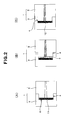
- Fig. 2 shows respective steps in a method for manufacturing a fiber-reinforced plastic according to another embodiment of the present invention.
- a mold 1 similar to that in the above-described embodiment, mold pieces 2, 3 disposed facing to each other of which have the fitting structure 4, is used, a reinforcing fiber base material 11 is placed in the cavity 5 of the mold, and first the mold is closed. At this step, the base material 11 is not compressed greatly.
- Fig. 2(B) for example, through one mold piece 2, melted thermoplastic resin 7 is injected and supplied into cavity 5 by injection, and by the resin pressure at the time of the injection, mold pieces 2, 3 are slightly opened to each other precisely via fitting structure 4.
- thermoplastic resin 7 filled in cavity 5 begins to impregnate into reinforcing fiber base material 11 having a relatively great porosity. Then, as shown in Fig. 2(C) , mold pieces 2, 3 are precisely closed to each other via fitting structure 4, and the volume of the above-described cavity 5 is reduced. By the reduction of the cavity volume at this stage, the inside of cavity 5 of mold 1 is compressed, and reinforcing fiber base material 11 after having been or while being impregnated with thermoplastic resin 7 is also compressed. Through this compression, an excellent resin impregnated state suppressed with voids can be obtained as well as a high fiber volume content can be achieved, and a fiber-reinforced plastic 12 having high mechanical properties can be obtained.
- Fig. 3 shows respective steps in a method for manufacturing a fiber-reinforced plastic according to a further embodiment of the present invention.
- a mold 21 which forms a cavity 24 between mold pieces 22, 23 disposed facing to each other, is used.
- a movable core 25 capable of moving in the cavity 24 is provided, and the movable core 25 can forcibly move in both directions in the cavity 24 by a driving means 26 provided in one mold piece 23 (for example, a driving means comprising a ball screw).
- a reinforcing fiber base material 27 made as aforementioned and having a relatively low apparent porosity is placed in the cavity 24 of the mold 21.
- a valve 28 provided in the other mold piece 22 is opened, and the inside of the cavity 24 is reduced in pressure by the suction operation (shown by an arrow) through a suction path 29.
- the cavity 24 is sealed from outside by a seal material 30 disposed between mold pieces 22, 23.
- a seal material 30 disposed between mold pieces 22, 23.
- melted thermoplastic resin 31 is injected and supplied into cavity 24 by injection.
- valve 28 is closed, and resin clogging of suction path 29 is avoided.
- the melted thermoplastic resin 31 filled in cavity 24 begins to impregnate into reinforcing fiber base material 27 having a relatively great porosity. Then, as shown in Fig.
- movable core 25 is forcibly moved in cavity 24 by driving means 26, and the volume of the cavity 24 is reduced.
- reinforcing fiber base material 27 after having been or while being impregnated with thermoplastic resin 31 is also compressed.
- an excellent resin impregnated state suppressed with voids can be obtained as well as a high fiber volume content can be achieved, and a fiber-reinforced plastic 32 having high mechanical properties can be obtained.
- the method according to the present invention can be applied to manufacturing of any fiber-reinforced plastic a matrix resin of which is basically a thermoplastic resin.
Landscapes
- Engineering & Computer Science (AREA)
- Mechanical Engineering (AREA)
- Chemical & Material Sciences (AREA)
- Composite Materials (AREA)
- Manufacturing & Machinery (AREA)
- Textile Engineering (AREA)
- Casting Or Compression Moulding Of Plastics Or The Like (AREA)
- Reinforced Plastic Materials (AREA)
Abstract
Description
- The present invention relates to a method for manufacturing a fiber-reinforced plastic, and specifically, to a method for manufacturing a fiber-reinforced plastic capable of molding a fiber-reinforced plastic having high mechanical properties easily and inexpensively even if it has a complicated shape.
- A fiber-reinforced plastic made of reinforcing fibers and a matrix resin (also referred to as "FRP" [Fiber Reinforced Plastic]), in particular, a carbon fiber-reinforced plastic made of carbon fibers and a matrix resin (also referred to as "CFRP" [Carbon Fiber Reinforced Plastic]), is developed broadly in various uses, because of its excellent mechanical properties, property light in weight, corrosion resistance, etc. As a method for manufacturing an FRP, although there is a method for using a so-called prepreg which is impregnated with a resin in advance, in case where it is required to broaden the range of the moldable shape of FRP and to shorten the time required for molding, for example, in case where a mass production is required such as in parts for vehicles or parts for electronic equipment, a method is frequently employed wherein a reinforcing fiber base material (dry-type reinforcing fiber base material) substantially containing no resin is formed in a predetermined shape, and by impregnating a matrix resin thereinto, a desired FRP is molded.
- In such a molding of FRP, in case where a thermosetting resin is used as the matrix resin, because the viscosity of the thermosetting resin before being cured is low, the resin can be cured after it is impregnated into a reinforcing fiber base material in a mold. In this method, there is an advantage that an expensive autoclave is not required and the time for molding may be relatively short.
- On the other hand, in order to mold an FRP having a more complicated shape, in particular, in order to conform it also to a mass-production article, it is considered that it is preferred to use a thermoplastic resin better in moldability as the matrix resin. However, because a thermoplastic resin is generally high in viscosity at the time of being melted as compared with a thermosetting resin, it is frequently difficult to impregnate a melted resin into a reinforcing fiber base material well in a short period of time, and it has been difficult to manufacture an FRP with a high productivity by a molding method wherein a resin is impregnated into a reinforcing fiber base material in a mold.
- In order to use a thermoplastic resin as a matrix resin and impregnate it into a reinforcing fiber base material at a relatively good condition, it is considered to form a reinforcing fiber base material in a non-woven fabric-like form by using discontinuous reinforcing fibers, thereby making the porosity of the base material high and facilitating the impregnation of the resin having a high viscosity. However, even in such a reinforcing fiber base material having a high porosity, it is not easy to impregnate a thermoplastic resin thereinto, and only a method has been known wherein a matrix resin is once formed in a sheet-like shape such as a non-woven fabric and it is pressed while being heated at a condition of being stacked with a reinforcing fiber base material (for example,
Patent documents 1 and 2). Even if such a reinforcing fiber base material having a high porosity is placed in a mold for injection molding and a thermoplastic resin is injected, only a CFRP having a very low fiber content or having many pores (voids) has been able to be obtained. -
- Patent document 1:
JP-A-2010-037358 - Patent document 2:
JP-A-2010-235779 - Accordingly, an object of the present invention is to provide a method for manufacturing a fiber-reinforced plastic which can mold a fiber-reinforced plastic having high mechanical properties easily and inexpensively even if it has a complicated shape.
- To achieve the above-described object, a method for manufacturing a fiber-reinforced plastic according to the present invention comprises steps for placing a compressible reinforcing fiber base material made of discontinuous reinforcing fibers in a cavity of a mold, injecting melted thermoplastic resin into the cavity, and impregnating it into the reinforcing fiber base material, and the method is characterized in that the mold is configured as one capable of changing a cavity volume of the mold, and the reinforcing fiber base material after having been or while being impregnated with the thermoplastic resin is compressed in the cavity by reducing the cavity volume of the mold after injecting the melted thermoplastic resin.
- In such a method for manufacturing a fiber-reinforced plastic according to the present invention, because the reinforcing fiber base material is made of discontinuous reinforcing fibers, it is formed as a base material the porosity of which is high as compared with that of a dense woven fabric base material and the like and which can be impregnated with a melted thermoplastic resin with a high viscosity relatively easily. Therefore, with respect to only this reinforcing fiber base material, it has a good resin impregnation ability and exhibits an excellent moldability from this point of view. However, merely by impregnating the high-viscosity thermoplastic resin into this reinforcing fiber base material, as aforementioned, because the fiber volume content of the reinforcing fibers becomes low, and desirable high mechanical properties cannot be obtained or voids in an FRP increase when the FRP is molded, an FRP having a good quality can be hardly obtained. Accordingly, in the present invention, when such a reinforcing fiber base material having a good resin impregnation ability is placed in a cavity of a mold and the melted thermoplastic resin is injected into the mold after the mold is heated, for example, before or after the reinforcing fiber base material is placed in the mold, the mold has been configured as one capable of changing the cavity volume, and after the melted thermoplastic resin is injected into the cavity of the mold, the cavity volume of the mold is reduced mechanically. Then, by this reduction of the cavity volume of the mold, the above-described reinforcing fiber base material having been or being impregnated with the thermoplastic resin is compressed in the cavity. By this compression of the reinforcing fiber base material in the cavity, its apparent porosity is made smaller, the fiber volume content of an FRP to be molded is made higher, and high mechanical properties as the FRP can be realized. Further, at the same time, by the condition where the apparent porosity of the reinforcing fiber base material is made smaller, voids being enclosed in the base material are pushed out or suppressed to be very small, thereby ensuring a good quality of an FRP after molding. Concretely, for example, by forming a space in the cavity at the stage of placing the reinforcing fiber base material in the cavity and injecting the melted thermoplastic resin into this space, the resin is easily filled in the space, and by pressing substantially after the filling, the resin can be quickly impregnated into the base material with the high porosity from the entire surface of the reinforcing fiber base material facing the space at a small distance for impregnation. As well as that, because the reinforcing fiber base material is also compressed by the pressing, the fiber volume content is increased, and high mechanical properties as FRP can be obtained. Furthermore, because the reinforcing fiber base material made of discontinuous reinforcing fibers, for example, formed as a non-woven fabric-like material, has an excellent formability, it can be adapted to a complicated molding shape, and by using such a reinforcing fiber base material, a good moldability can be maintained. This good moldability is not damaged at all by the above-described compression in the mold after the reinforcing fiber base material is placed in the mold. Namely, while the good moldability is maintained, high mechanical properties and good quality as FRP can be easily ensured.
- In the above-described method for manufacturing a fiber-reinforced plastic according to the present invention, the reduction of the cavity volume of the mold can be carried out as follows. For example, after injecting the melted thermoplastic resin into the cavity of the mold at a condition where the mold is opened in advance, the cavity volume of the mold is reduced by closing the mold. Further, after placing the above-described reinforcing fiber base material in the cavity of the mold and closing the mold, the cavity volume may also be reduced after the mold is opened by a resin pressure at which the above-described melted thermoplastic resin is injected into the cavity. Even in any of the above-described methods, a thermoplastic resin can be impregnated easily and satisfactorily into the reinforcing fiber base material at a condition where the base material has a high apparent porosity and a good resin impregnation ability and the reinforcing fiber base material after having been or while being impregnated with the resin can be compressed in the mold, thereby enhancing the fiber volume content of an FRP to be molded and realizing high mechanical properties as the FRP.
- Further, in the above-described reduction of the cavity volume of the mold, it is preferred that the compression force at the time of reducing the cavity volume is 10 MPa or more. Namely, because in the cavity the reinforcing fiber base material after having been or while being impregnated with the resin is to be compressed, in order to achieve a sufficiently low apparent porosity (sufficiently high fiber volume content) by compression, the compression force is preferably 10 MPa or more.
- Further, as the above-described mold capable of changing the cavity volume, for example, a mold, mold pieces disposed facing to each other of which can be closed and opened via a fitting structure or a movable core, can be used. Namely, in a mold having a fitting structure, the cavity volume can be reduced by operating the mold pieces, which are in an opening condition, in the mold closing direction to each other. In a mold equipped with a movable core, the cavity volume can be reduced by operating the movable core in a specified direction in the cavity. However, as long as it is a mold capable of changing its cavity volume, a mold having a structure other than those structures can be used.
- Further, with respect to the above-described injection of the melted thermoplastic resin into the cavity, the melted thermoplastic resin can also be injected at a condition where the pressure in the cavity is reduced, and the cavity volume may be reduced after the resin injection. Because gas can be smoothly discharged from the reinforcing fiber base material by the pressure reduction, generation of voids due to gas can be suppressed further satisfactorily. Further, by injecting the melted thermoplastic resin in to the pressure-reduced cavity, it becomes possible to distribute the resin in the cavity more easily and uniformly.
- Further, in the method for manufacturing a fiber-reinforced plastic according to the present invention, it is preferred that the reinforcing fiber base material has initial properties of a porosity as high as possible and an ability easily impregnated with a high-viscosity melted thermoplastic resin. On the other hand, it is preferred that, after the above-described predetermined compression in the mold, the porosity is suppressed as low as possible in order to achieve a high fiber volume content. From such a point of view, in the present invention, as the property of the above-described reinforcing fiber base material itself, it is preferred that the apparent porosity of the base material at the time of being compressed at 2 MPa (namely, at the time of being compressed at a small pressure in order to define the property of the base material itself quantitatively) is 70% or more. Further, it is preferred that the apparent porosity of the above-described reinforcing fiber base material at the time of being compressed at 10 MPa is 40% or less.
- Further, in the present invention, although the kind of the reinforcing fibers of the above-described reinforcing fiber base material is not particularly restricted and carbon fibers, glass fibers, aramide fibers and the like, and further, reinforcing fibers with a hybrid structure combined by these fibers, can be used, in order to realize higher mechanical properties, it is preferred that the reinforcing fibers of the above-described reinforcing fiber base material comprise carbon fibers.
- Further, in the present invention, in case where the reinforcing fibers of the above-described reinforcing fiber base material comprise carbon fibers, in order to realize high mechanical properties, it is preferred that the weight average fiber length of carbon fibers contained in the reinforcing fiber base material is 1 mm or more. If the weight average fiber length is too short, the function as reinforcing fibers becomes poor, and an effect for enhancing the mechanical properties becomes small. Further, in order to maintain the aforementioned good moldability, it is preferred that the weight average fiber length of carbon fibers contained in the reinforcing fiber base material is 100 mm or less. If the weight average fiber length is too long, because they become close to continuous fibers, there is a fear that the formability of the base material and the moldability of FRP are lowered.
- Further, in the present invention, it is possible to contain a thermoplastic resin in the reinforcing fiber base material by 3 to 50 wt.%. This thermoplastic resin mainly has a function of adhesion for holding a formation of the reinforcing fiber base material, and it is different from the function of a matrix resin for molding an FRP. However, the kind of the resin may be same as that of the matrix resin.
- Further, in the present invention, in order to ensure a good formability of the base material and ensure a good resin impregnation property into the base material, it is desired that the above-described reinforcing fiber base material made of discontinuous reinforcing fibers is formed in a formation of a nonwoven fabric. Such a desirable formation can be realized by the reinforcing fiber base material made by paper making method, or by the reinforcing fiber base material made by a carding machine.
- Further, in the present invention, in particular, in case where more excellent formability of the base material and molding of FRP into a more complicated shape are required, the above-described reinforcing fiber base material is formed preferably as a formation in which the discontinuous reinforcing fibers are randomly oriented. On the other hand, in case where high mechanical properties in a specified direction are desired to be exhibited in an FRP to be molded, the above-described reinforcing fiber base material is formed preferably as a formation in which at least a part of the discontinuous reinforcing fibers are oriented in the specified direction. It can be realized also by the above-described carding machine to thus orient at least a part of the discontinuous reinforcing fibers in a specified direction.
- Further, in case where at least a part of the discontinuous reinforcing fibers are oriented in a specified direction as described above, it is possible to control a ratio of an elastic modulus in the specified direction to an elastic modulus in a direction perpendicular to the specified direction of a fiber-reinforced plastic after molding, for example, in a range of 2:1 to 10:1.
- Further, in the present invention, although the kind of the above-described thermoplastic resin as the matrix resin impregnated into the above-described reinforcing fiber base material is not particularly restricted, its temperature for molding is preferably, for example, 100°C or higher. For example, in the present invention, in case where the mold is heated at a temperature of 100°C or higher, it is particularly preferable that the temperature for molding of the thermoplastic resin is 100°C or higher.
- As a thermoplastic resin usable in the present invention, for example, one selected from the group consisting of a polyolefin, a polyamide, a polyester, a polyphenylene sulfide, a polycarbonate, a polyetherketone and a polyetherimide can be exemplified.
- Further, in the present invention, as the above-described mold, a mold for injection-compression molding, in which a gas vent is provided to a cavity part positioned at an opposite side relatively to a gate filled with the thermoplastic resin, can be used. If such a mold is used, when the melted thermoplastic resin is injected into the cavity of the mold, gas is adequately discharged through the gas vent as well as gas is adequately discharged also when the cavity volume of the mold is reduced, and it becomes possible to perform the compression molding more smoothly.
- Further, in the present invention, a base material, in which the above-described compressible reinforcing fiber base material is held in a resin film pack at a pressure reduced condition, can also be used, and the base material with such a formation can be placed in the cavity of the mold. If the base material with such a formation is used, it becomes possible to maintain a desirable compressible condition of the reinforcing fiber base material also during handling, and it becomes possible to serve it to compression only when the compression is required.
- Furthermore, in the present invention, although there is a case where reinforcing fibers exist at a fiber bundle condition in the above-described compressible reinforcing fiber base material, in such a case, if the rate of the fiber bundles in the reinforcing fiber base material becomes too much, there is a fear that the flowability of the resin containing the reinforcing fibers at the time of compression molding is damaged. Therefore, in the compressible reinforcing fiber base material, it is preferred to suppress the fiber bundles each having 50 to 1,000 reinforcing fibers at an amount of 80 wt.% or less relative to the whole of the compressible reinforcing fiber base material.
- Thus, in the present invention, a fiber-reinforced plastic having high mechanical properties can be molded easily and inexpensively even if it has a complicated shape.
-
- [
Fig. 1] Fig. 1 depicts schematic sectional views of a mold showing respective steps in a method for manufacturing a fiber-reinforced plastic according to an embodiment of the present invention. - [
Fig. 2] Fig. 2 depicts schematic sectional views of a mold showing respective steps in a method for manufacturing a fiber-reinforced plastic according to another embodiment of the present invention. - [
Fig. 3] Fig. 3 depicts schematic sectional views of a mold showing respective steps in a method for manufacturing a fiber-reinforced plastic according to a further embodiment of the present invention. - [
Fig. 4] Fig. 4 is a schematic diagram in case where a reinforcing fiber base material is made by a carding machine in the present invention. - Hereinafter, more concrete embodiments of the present invention will be explained.
- For example, carbon fibers cut at a weight average fiber length of 50 mm are used as discontinuous reinforcing fibers, and the carbon fibers are supplied to a carding machine to make a compressible sheet-like carbon fiber base material. This base material sheet is placed, for example, in a cavity of a mold equipped in an injection press machine. After placing the base material, the mold is heated at a temperature of 100°C or higher, and for example, a melted polyamide resin as a thermoplastic resin is injected into the cavity of the mold. Together with the injection or after the injection, although the inside of the mold is compressed by reducing the cavity volume of the mold, examples of the compression operation due to this reduction of the cavity volume of the mold will be described later referring to
Fig. 1 to Fig. 3 . - The above-described making the carbon fiber base material by a carding machine is carried out, for example, as follows.
Fig. 4 shows a schematic diagram in case where a reinforcing fiber base material is made by a carding machine in the present invention. A cardingmachine 1 shown inFig. 4 mainly comprises acylinder roll 42, a take-inroll 43 provided at an upstream side and closely to the outer circumferential surface of thecylinder roll 42, adoffer roll 44 provided closely to the outer circumferential surface of thecylinder roll 42 at a downstream side which is a side opposite to the side of the take-inroll 43, a plurality of worker rolls 45 provided closely to the outer circumferential surface of thecylinder roll 42 between the take-inroll 43 and thedoffer roll 44, stripper rolls 46 provided closely to the worker rolls 45, and afeed roll 47 provided closely to the take-inroll 43, and abelt conveyer 48. - Aggregates of
discontinuous carbon fibers 49, which are cut, for example, at a weight average fiber length of 50 mm, are supplied ontobelt conveyer 48, and thediscontinuous carbon fibers 49 are introduced onto the outer circumferential surface ofcylinder roll 42 through the outer circumferential surface offeed roll 47 and then through the outer circumferential surface of take-inroll 43. Up to this stage,discontinuous carbon fibers 49 become a floc-like form. Although a part of the floc-like carbon fibers introduced onto the outer circumferential surface ofcylinder roll 42 wind around the outer circumferential surface of the respective worker rolls 45, these carbon fibers are stripped off by the respective stripper rolls 46 and returned again onto the outer circumferential surface of thecylinder roll 42. Many needles, projections exist at standing conditions on the outer circumferential surfaces of the respective rolls offeed roll 47, take-inroll 43,cylinder roll 42, worker rolls 45 and stripper rolls 46, and in the above-described steps, by the operation of the needles, carbon fibers are refined into a single-fiber condition and at the same time the directions of most carbon fibers are arranged in a specified direction, namely, in the rotational direction ofcylinder roll 42. The carbon fibers, refined and promoted in fiber orientation through such steps, move onto the outer circumferential surface ofdoffer roll 44 as a sheet-like web 50 which is one form of a carbon fiber aggregate. Further, by drawing theweb 50 while narrowing the width thereof to a predetermined width, a sheet-like base material made of discontinuous carbon fibers defined in the present invention is formed. - In the carding as described above, although the aggregate of
discontinuous carbon fibers 49 may be formed by only carbon fibers, the carding can also be performed at a condition mixed with discontinuous organic fibers, in particular, thermoplastic resin fibers. In particular, it is preferred to add thermoplastic resin fibers when the carding is performed, because breakage of carbon fibers at the carding can be prevented. Because carbon fibers are rigid and fragile, they are hard to be tangled and liable to be broken. Therefore, there is a problem in the carbon fiber aggregate formed by only carbon fibers that during the carding, carbon fibers are easily cut or carbon fibers are liable to be fallen off. Accordingly, by containing thermoplastic resin fibers which are flexible and easily tangled, a carbon fiber aggregate, in which the carbon fibers are hard to be cut and the carbon fibers are hard to be fallen off, can be formed. Further, it is also preferred to perform the carding mixing such organic fibers, in particular, thermoplastic resin fibers, after the carding, to perform pressing after melting at least a part of the organic fibers. Namely, it is also preferred that, by mixing an adequately small amount of thermoplastic resin fibers and melting at least a part of the thermoplastic resin fibers at a condition where carbon fibers are treated with a predetermined carding, for example, so that a part of carbon fibers are oriented in a specified direction, a function of a binder for maintaining a predetermined form of a sheet-like base material is given to the thermoplastic resin fibers, and by performing pressing at such a condition, the maintained form is appropriately fixed via the thermoplastic resin fibers. - In case where thermoplastic resin fibers are contained in a carbon fiber aggregate as described above, the content of carbon fibers in the carbon fiber aggregate is preferably in a range of 50 to 95 mass%, more preferably in a range of 70 to 95 mass%. If the rate of carbon fibers is low, it becomes difficult to obtain high mechanical properties when a carbon fiber-reinforced plastic is made, and to the contrary, if the rate of thermoplastic resin fibers is too low, the above-described function of the thermoplastic resin fibers when the thermoplastic resin fibers are mixed to the carbon fiber aggregate cannot be expected, or becomes poor.
- Further, it is preferred to provide a crimp to the above-described thermoplastic resin fibers in order to enhance the effect of tangle due to the thermoplastic resin fibers. Although the degree of the crimp is not particularly limited, generally, thermoplastic resin fibers having a number of crimp in a range of approximately 5 to 25 crests per 25 mm and a rate of crimp in a range of approximately 3 to 30% can be used.
- The material for such thermoplastic resin fibers is not particularly restricted, and it can be appropriately selected from a range that does not greatly reduce the mechanical properties of a carbon fiber-reinforced plastic. For example, fibers can be used which are prepared by spinning a resin such as a polyolefin-group resin such as polyethylene or polypropylene, a polyamide-group resin such as
nylon 6 ornylon - Further, a method of pressing, in case where as described above the carding is carried out at a condition of mixing thermoplastic resin fibers to carbon fibers, and after the carding, the pressing is performed after melting at least a part of the thermoplastic resin fibers, is not particularly restricted, and for example, a usual press machine for pressing at a condition of nipping with a flat plate, a calender roll machine for pressing at a condition of nipping with a pair of rolls, etc. can be employed.
- Where, although in the above description the method for making a carbon fiber base material after the treatment of carding has been exemplified, it is also possible to make a carbon fiber base material merely by paper making method without performing carding. For example, it is also possible to make a sheet-like carbon fiber base material by supplying aggregates of
discontinuous carbon fibers 49 cut at a weight average fiber length of 50 mm ontobelt conveyer 48 inFig. 4 and pressing them, for example, by suing the calender roll machine and the like as described above. In this case, similarly to the above description, it is preferred to mix thermoplastic resin fibers in the carbon fiber aggregates and give the thermoplastic resin fibers a function of a binder for maintaining the sheet-like base material form. - Further, by the above-described treatment using a calender roll machine and the like or a similar treatment, a property of the base material itself, in particular, the aforementioned apparent porosity of the base material at the time of being compressed at 2 MPa or apparent porosity of the base material at the time of being compressed at 10 MPa, can be controlled at a desired property.
- Thus, by using a base material made so as to have a desirable compression property, placing the compressible base material in a mold, heating the mold at a temperature of, for example, 100°C or higher before placing the base material or after placing the base material, injecting the melted thermoplastic resin into the mold by injection and the like, and compressing the inside of the mold together with the injection or after the injection, even if a complicated shape is molded, a fiber-reinforced plastic having high mechanical properties can be manufactured easily and inexpensively.
- Hereinafter, the compression operation due to the reduction of the cavity volume of the mold in the present invention will be exemplified referring to
Fig. 1 to Fig. 3 . -
Fig. 1 shows respective steps in a method for manufacturing a fiber-reinforced plastic according to an embodiment of the present invention. As shown inFig. 1(A) , amold 1,mold pieces fitting structure 4, is used, and a reinforcingfiber base material 6 made as aforementioned and having a relatively low apparent porosity is placed in acavity 5 of themold 1 which is in a mold opened condition. At this condition, as shown inFig. 1(B) , for example, through onemold piece 2, meltedthermoplastic resin 7 is injected and supplied intocavity 5 by injection. Then, as shown inFig. 1(C) ,mold pieces fitting structure 4, and the volume of the above-describedcavity 5 is reduced. By this reduction of the cavity volume, the inside ofcavity 5 ofmold 1 is compressed, and reinforcingfiber base material 6 after having been or while being impregnated withthermoplastic resin 7 is also compressed. Through this compression, an excellent resin impregnated state suppressed with voids can be obtained as well as a high fiber volume content can be achieved, and a fiber-reinforcedplastic 8 having high mechanical properties can be obtained. -
Fig. 2 shows respective steps in a method for manufacturing a fiber-reinforced plastic according to another embodiment of the present invention. As shown inFig. 2(A) , amold 1 similar to that in the above-described embodiment,mold pieces fitting structure 4, is used, a reinforcingfiber base material 11 is placed in thecavity 5 of the mold, and first the mold is closed. At this step, thebase material 11 is not compressed greatly. At this condition, as shown inFig. 2(B) , for example, through onemold piece 2, meltedthermoplastic resin 7 is injected and supplied intocavity 5 by injection, and by the resin pressure at the time of the injection,mold pieces fitting structure 4. The meltedthermoplastic resin 7 filled incavity 5 begins to impregnate into reinforcingfiber base material 11 having a relatively great porosity. Then, as shown inFig. 2(C) ,mold pieces fitting structure 4, and the volume of the above-describedcavity 5 is reduced. By the reduction of the cavity volume at this stage, the inside ofcavity 5 ofmold 1 is compressed, and reinforcingfiber base material 11 after having been or while being impregnated withthermoplastic resin 7 is also compressed. Through this compression, an excellent resin impregnated state suppressed with voids can be obtained as well as a high fiber volume content can be achieved, and a fiber-reinforcedplastic 12 having high mechanical properties can be obtained. -
Fig. 3 shows respective steps in a method for manufacturing a fiber-reinforced plastic according to a further embodiment of the present invention. As shown inFig. 3(A) , amold 21, which forms acavity 24 betweenmold pieces cavity 24, amovable core 25 capable of moving in thecavity 24 is provided, and themovable core 25 can forcibly move in both directions in thecavity 24 by a driving means 26 provided in one mold piece 23 (for example, a driving means comprising a ball screw). A reinforcingfiber base material 27 made as aforementioned and having a relatively low apparent porosity is placed in thecavity 24 of themold 21. After placing the reinforcingfiber base material 27, avalve 28 provided in theother mold piece 22 is opened, and the inside of thecavity 24 is reduced in pressure by the suction operation (shown by an arrow) through asuction path 29. At that time, thecavity 24 is sealed from outside by aseal material 30 disposed betweenmold pieces Fig. 3(B) , for example, through onemold piece 22, meltedthermoplastic resin 31 is injected and supplied intocavity 24 by injection. At this time,valve 28 is closed, and resin clogging ofsuction path 29 is avoided. The meltedthermoplastic resin 31 filled incavity 24 begins to impregnate into reinforcingfiber base material 27 having a relatively great porosity. Then, as shown inFig. 3(C) ,movable core 25 is forcibly moved incavity 24 by drivingmeans 26, and the volume of thecavity 24 is reduced. By this reduction of the cavity volume, reinforcingfiber base material 27 after having been or while being impregnated withthermoplastic resin 31 is also compressed. Through this compression, an excellent resin impregnated state suppressed with voids can be obtained as well as a high fiber volume content can be achieved, and a fiber-reinforcedplastic 32 having high mechanical properties can be obtained. - The method according to the present invention can be applied to manufacturing of any fiber-reinforced plastic a matrix resin of which is basically a thermoplastic resin.
-
- 1, 21:
- mold
- 2, 3, 22, 23:
- mold piece
- 4:
- fitting structure
- 5, 24:
- cavity
- 6, 11, 27:
- reinforcing fiber base material
- 7, 31:
- thermoplastic resin
- 8, 12, 32:
- fiber-reinforced plastic
- 25:
- movable core
- 26:
- driving means
- 28:
- valve
- 29:
- suction path
- 30:
- seal material
- 41:
- carding machine
- 42:
- cylinder roll
- 43:
- take-in roll
- 44:
- doffer roll
- 45:
- worker roll
- 46:
- stripper roll
- 47:
- feed roll
- 48:
- belt conveyer
- 49:
- discontinuous carbon fibers
- 50:
- sheet-like web
Claims (20)
- A method for manufacturing a fiber-reinforced plastic that comprises steps for placing a compressible reinforcing fiber base material made of discontinuous reinforcing fibers in a cavity of a mold, injecting melted thermoplastic resin into said cavity, and impregnating it into said reinforcing fiber base material, characterized in that said mold is configured as one capable of changing a cavity volume of said mold, and said reinforcing fiber base material after having been or while being impregnated with said thermoplastic resin is compressed in said cavity by reducing said cavity volume of said mold after injecting said melted thermoplastic resin.
- The method for manufacturing a fiber-reinforced plastic according to claim 1, wherein, after injecting said melted thermoplastic resin into said cavity of said mold at a condition where said mold is opened in advance, said cavity volume of said mold is reduced by closing said mold.
- The method for manufacturing a fiber-reinforced plastic according to claim 1, wherein, after placing said reinforcing fiber base material in said cavity of said mold and closing said mold, said cavity volume is reduced after said mold is opened by a resin pressure at which said melted thermoplastic resin is injected into said cavity.
- The method for manufacturing a fiber-reinforced plastic according to any of claims 1 to 3, wherein a compression force at the time of reducing said cavity volume is 10 MPa or more.
- The method for manufacturing a fiber-reinforced plastic according to any of claims 1 to 4, wherein a mold, mold pieces disposed facing to each other of which can be closed and opened via a fitting structure or a movable core, is used as said mold capable of changing said cavity volume.
- The method for manufacturing a fiber-reinforced plastic according to any of claims 1 to 5, wherein said cavity volume is reduced after said melted thermoplastic resin is injected at a condition where a pressure in said cavity is reduced.
- The method for manufacturing a fiber-reinforced plastic according to any of claims 1 to 6, wherein a base material, an apparent porosity of which at the time of being compressed at 2 MPa is 70% or more, is used as said compressible reinforcing fiber base material.
- The method for manufacturing a fiber-reinforced plastic according to any of claims 1 to 7, wherein a base material, an apparent porosity of which at the time of being compressed at 10 MPa is 40% or less, is used as said compressible reinforcing fiber base material.
- The method for manufacturing a fiber-reinforced plastic according to any of claims 1 to 8, wherein reinforcing fibers of said reinforcing fiber base material comprise carbon fibers.
- The method for manufacturing a fiber-reinforced plastic according to claim 9, wherein a weight average fiber length of said carbon fibers contained in said reinforcing fiber base material is 1 mm or more and 100 mm or less.
- The method for manufacturing a fiber-reinforced plastic according to any of claims 1 to 10, wherein a thermoplastic resin is contained in said reinforcing fiber base material by 3 to 50 wt.%.
- The method for manufacturing a fiber-reinforced plastic according to any of claims 1 to 11, wherein said reinforcing fiber base material is one made by paper making method.
- The method for manufacturing a fiber-reinforced plastic according to any of claims 1 to 11, wherein said reinforcing fiber base material is one made by a carding machine.
- The method for manufacturing a fiber-reinforced plastic according to any of claims 1 to 13, wherein said reinforcing fiber base material is one in which said discontinuous reinforcing fibers are randomly oriented.
- The method for manufacturing a fiber-reinforced plastic according to any of claims 1 to 13, wherein said reinforcing fiber base material is one in which at least a part of said discontinuous reinforcing fibers are oriented in a specified direction.
- The method for manufacturing a fiber-reinforced plastic according to claim 15, wherein a ratio of an elastic modulus in said specified direction to an elastic modulus in a direction perpendicular to said specified direction of a fiber-reinforced plastic after molding is in a range of 2:1 to 10:1.
- The method for manufacturing a fiber-reinforced plastic according to any of claims 1 to 16, wherein a temperature for molding of said thermoplastic resin is 100°C or higher.
- The method for manufacturing a fiber-reinforced plastic according to any of claims 1 to 17, wherein said thermoplastic resin comprises one selected from the group consisting of a polyolefin, a polyamide, a polyester, a polyphenylene sulfide, a polycarbonate, a polyetherketone and a polyetherimide.
- The method for manufacturing a fiber-reinforced plastic according to any of claims 1 to 18, wherein, as said mold, a mold for injection-compression molding, in which a gas vent is provided to a cavity part positioned at an opposite side relatively to a gate filled with said thermoplastic resin, is used.
- The method for manufacturing a fiber-reinforced plastic according to any of claims 1 to 19, wherein a base material, in which said compressible reinforcing fiber base material is held in a resin film pack at a pressure reduced condition, is placed in said cavity of said mold.
Applications Claiming Priority (3)
| Application Number | Priority Date | Filing Date | Title |
|---|---|---|---|
| JP2011134451 | 2011-06-16 | ||
| JP2011148952 | 2011-07-05 | ||
| PCT/JP2012/064023 WO2012172982A1 (en) | 2011-06-16 | 2012-05-31 | Method for manufacturing fiber-reinforced plastic |
Publications (2)
| Publication Number | Publication Date |
|---|---|
| EP2722147A1 true EP2722147A1 (en) | 2014-04-23 |
| EP2722147A4 EP2722147A4 (en) | 2015-12-30 |
Family
ID=47356974
Family Applications (1)
| Application Number | Title | Priority Date | Filing Date |
|---|---|---|---|
| EP12800101.3A Withdrawn EP2722147A4 (en) | 2011-06-16 | 2012-05-31 | Method for manufacturing fiber-reinforced plastic |
Country Status (5)
| Country | Link |
|---|---|
| US (1) | US9011747B2 (en) |
| EP (1) | EP2722147A4 (en) |
| JP (1) | JP5862575B2 (en) |
| CN (1) | CN103561931B (en) |
| WO (1) | WO2012172982A1 (en) |
Cited By (3)
| Publication number | Priority date | Publication date | Assignee | Title |
|---|---|---|---|---|
| DE102014201380A1 (en) * | 2014-01-27 | 2015-07-30 | Bayerische Motoren Werke Aktiengesellschaft | Process for producing a fiber-reinforced hollow profile component |
| FR3028797A1 (en) * | 2014-11-21 | 2016-05-27 | Anthony Bertrand Patrick Mahe | SEQUENTIAL IMPREGNATION METHOD OF A TEXTILE STRUCTURE |
| CN111391216A (en) * | 2020-03-19 | 2020-07-10 | 福建省闽清双棱竹业有限公司 | Hot press for bamboo-plastic composite board and hot pressing process |
Families Citing this family (18)
| Publication number | Priority date | Publication date | Assignee | Title |
|---|---|---|---|---|
| JP6021262B2 (en) * | 2013-01-17 | 2016-11-09 | 株式会社名機製作所 | Compression molding method for fiber composite molded article and compression molding apparatus for fiber composite molded article |
| DE102014007869B4 (en) * | 2014-06-03 | 2016-02-11 | Airbus Defence and Space GmbH | Apparatus and method for infiltrating fiber material with resin to produce a fiber composite component |
| JP6602552B2 (en) * | 2015-04-14 | 2019-11-06 | 国立大学法人岐阜大学 | Manufacturing method of molded body |
| EP3284574A4 (en) | 2015-04-17 | 2018-04-25 | Mitsubishi Chemical Corporation | Fiber-reinforced composite material molded article and method for manufacturing same |
| JP6560955B2 (en) * | 2015-10-19 | 2019-08-14 | 株式会社イノアックコーポレーション | Manufacturing method of composite member |
| CN108778661B (en) * | 2016-03-24 | 2020-08-11 | 本田技研工业株式会社 | FRP sheet press forming method and apparatus, and FRP formed product |
| US11890793B2 (en) * | 2016-05-25 | 2024-02-06 | Basf Se | Assembling fiber-reinforced foams |
| JP6426684B2 (en) * | 2016-12-15 | 2018-11-21 | 本田技研工業株式会社 | Method of manufacturing fiber reinforced resin molded article |
| US11230067B2 (en) * | 2017-03-01 | 2022-01-25 | Nissan Motor Co., Ltd. | Carbon fiber-reinforced resin molded body and manufacturing method thereof |
| JP6895280B2 (en) * | 2017-03-13 | 2021-06-30 | 株式会社東芝 | Membrane member and its manufacturing method |
| EP3427921B1 (en) | 2017-07-14 | 2021-11-17 | Crompton Technology Group Limited | Composite ball screw |
| CN109278242B (en) * | 2018-09-06 | 2019-11-12 | 华中科技大学 | A method for integrally forming a thermoplastic composite structure on a resin plastic part |
| CN110027226B (en) * | 2019-02-28 | 2020-09-15 | 东华大学 | P-RTM (resin transfer molding) forming process for preparing reinforced composite material |
| US12296511B2 (en) * | 2019-06-12 | 2025-05-13 | Mitsubishi Gas Chemical Company, Inc. | Method for producing molded article |
| EP3984715B1 (en) * | 2020-10-13 | 2023-11-15 | Technische Universität München | Fiber-reinforced soluble core and method for its manufacture |
| CN112706432A (en) * | 2021-01-20 | 2021-04-27 | 惠州市奔达建材实业有限公司 | Preparation method of fiber reinforced plastic concrete |
| CN115592981B (en) * | 2022-10-14 | 2023-10-13 | 惠州硕贝德新材料技术有限公司 | Thermoplastic forming process for impregnating compound |
| US20240383213A1 (en) * | 2023-05-19 | 2024-11-21 | B/E Aerospace, Inc | Three dimensional preform based thermoplastic composite panels for ballistic applications formed by compression resin transfer molding |
Family Cites Families (20)
| Publication number | Priority date | Publication date | Assignee | Title |
|---|---|---|---|---|
| DE69021361T2 (en) * | 1989-08-21 | 1996-02-29 | Sumitomo Chemical Co., Ltd., Osaka | METHOD FOR PRODUCING A FIBER REINFORCED THERMOPLASTIC PLASTIC MOLDED PRODUCT. |
| JP2917372B2 (en) | 1990-03-09 | 1999-07-12 | 住友化学工業株式会社 | Method for producing fiber-reinforced thermoplastic resin molded article |
| JP2503782B2 (en) * | 1990-12-21 | 1996-06-05 | 住友化学工業株式会社 | Molding method for multi-layer molded products |
| US5424017A (en) * | 1993-04-12 | 1995-06-13 | Hinduja; Murli L. | Method for forming fiber-reinforced articles |
| US5518385A (en) * | 1994-11-09 | 1996-05-21 | United Technologies Corporation | Apparatus for resin transfer molding |
| JP3310484B2 (en) * | 1994-12-22 | 2002-08-05 | トヨタ自動車株式会社 | Fiber reinforced resin composite |
| JP3767465B2 (en) | 2001-11-27 | 2006-04-19 | 松下電工株式会社 | Method for producing thin-walled molded product and molding die apparatus used therefor |
| JP2003211500A (en) * | 2002-01-23 | 2003-07-29 | Matsushita Electric Ind Co Ltd | Mold and method for molding plastic lens |
| DE10258630A1 (en) * | 2002-12-16 | 2004-07-08 | Daimlerchrysler Ag | Long fiber reinforced thermoplastic component manufacture involves placing fiber preform in tool cavity, introduction of fluid plastic into the open tool and then tool closure of tool |
| JP4414801B2 (en) * | 2004-03-26 | 2010-02-10 | 日産自動車株式会社 | Method and apparatus for molding fiber reinforced plastic |
| CN101157265A (en) * | 2006-01-10 | 2008-04-09 | 马自达汽车株式会社 | Molding method and apparatus for making resin molded article |
| US8597562B2 (en) * | 2006-03-30 | 2013-12-03 | GM Global Technology Operations LLC | Composite products and methods of making the same |
| US7931845B2 (en) * | 2007-05-21 | 2011-04-26 | O & D Manufacturing | Gravity injection of molding material for compression molding and related methods |
| JP2009061767A (en) * | 2007-08-09 | 2009-03-26 | Meiki Co Ltd | Injection press molding method |
| JP2010037358A (en) | 2008-07-31 | 2010-02-18 | Toray Ind Inc | Method for manufacturing fiber-reinforced molded substrate |
| JP4862913B2 (en) | 2009-03-31 | 2012-01-25 | 東レ株式会社 | Prepregs and preforms |
| JP5557997B2 (en) * | 2008-11-19 | 2014-07-23 | 三菱重工業株式会社 | Fiber reinforced composite material manufacturing method and fiber reinforced composite material manufacturing apparatus |
| JP4825899B2 (en) * | 2009-06-22 | 2011-11-30 | トヨタ自動車株式会社 | Manufacturing method of fiber reinforced resin, manufacturing apparatus of fiber reinforced resin |
| JP5427503B2 (en) * | 2009-07-31 | 2014-02-26 | 日産自動車株式会社 | FIBER-REINFORCED RESIN COMPONENT, ITS MANUFACTURING METHOD, AND MANUFACTURING DEVICE |
| WO2011118226A1 (en) * | 2010-03-26 | 2011-09-29 | 三菱重工プラスチックテクノロジー株式会社 | Method for manufacturing a fiber-reinforced composite material |
-
2012
- 2012-05-31 US US14/125,207 patent/US9011747B2/en not_active Expired - Fee Related
- 2012-05-31 EP EP12800101.3A patent/EP2722147A4/en not_active Withdrawn
- 2012-05-31 JP JP2012549188A patent/JP5862575B2/en not_active Expired - Fee Related
- 2012-05-31 WO PCT/JP2012/064023 patent/WO2012172982A1/en not_active Ceased
- 2012-05-31 CN CN201280025548.0A patent/CN103561931B/en not_active Expired - Fee Related
Cited By (4)
| Publication number | Priority date | Publication date | Assignee | Title |
|---|---|---|---|---|
| DE102014201380A1 (en) * | 2014-01-27 | 2015-07-30 | Bayerische Motoren Werke Aktiengesellschaft | Process for producing a fiber-reinforced hollow profile component |
| DE102014201380B4 (en) * | 2014-01-27 | 2017-06-14 | Bayerische Motoren Werke Aktiengesellschaft | Process for producing a fiber-reinforced hollow profile component |
| FR3028797A1 (en) * | 2014-11-21 | 2016-05-27 | Anthony Bertrand Patrick Mahe | SEQUENTIAL IMPREGNATION METHOD OF A TEXTILE STRUCTURE |
| CN111391216A (en) * | 2020-03-19 | 2020-07-10 | 福建省闽清双棱竹业有限公司 | Hot press for bamboo-plastic composite board and hot pressing process |
Also Published As
| Publication number | Publication date |
|---|---|
| CN103561931B (en) | 2016-04-06 |
| EP2722147A4 (en) | 2015-12-30 |
| US9011747B2 (en) | 2015-04-21 |
| WO2012172982A1 (en) | 2012-12-20 |
| JP5862575B2 (en) | 2016-02-16 |
| JPWO2012172982A1 (en) | 2015-02-23 |
| US20140124976A1 (en) | 2014-05-08 |
| CN103561931A (en) | 2014-02-05 |
Similar Documents
| Publication | Publication Date | Title |
|---|---|---|
| US9011747B2 (en) | Method for manufacturing fiber-reinforced plastic | |
| US9469740B2 (en) | Carbon-fiber-reinforced plastic and process for producing same | |
| KR102085014B1 (en) | Method for forming shaped preform | |
| US8329280B2 (en) | Chopped fiber bundle, molding material, and fiber reinforced plastic, and process for producing them | |
| EP1731282B1 (en) | Preform, frp, and processes for producing these | |
| EP2733161A1 (en) | Thermoplastic resin pre-preg, molded preform and molded composite using same, and method for producing molded preform and molded composite | |
| CN103119209B (en) | The manufacture method of carbon fiber aggregate and the manufacture method of carbon fibre reinforced plastic | |
| US11084187B2 (en) | Fiber-reinforced composite material molded article and method for manufacturing same | |
| JP5691699B2 (en) | Press molding method and molded body thereof | |
| KR101684821B1 (en) | Manufacturing method for fibre-reinforced resin substrate or resin molded article, and plasticizing exhauster used in manufacturing method | |
| JP2015085613A (en) | Integrally molded body and method for producing the same | |
| US20080290560A1 (en) | Gravity injection of molding material for compression molding and related methods | |
| CN105531101B (en) | Method for manufacturing fiber reinforced parts | |
| JP2008307692A (en) | Fiber-reinforced plastic and method for producing the same | |
| JPWO2015194533A1 (en) | Method for producing molded body having opening | |
| KR102191092B1 (en) | Thermoplastic resin matrix fiber and carbon fiber-reinforced thermoplastic plastic composite having excellent impregnation property produced therefrom and manufacturing method thereof | |
| CN111699210B (en) | Dry tape material for fiber laying, manufacturing method thereof, and reinforced fiber laminate and fiber-reinforced resin molded body using the same | |
| CN114616090B (en) | Carbon fiber tape material, and reinforcing fiber laminate and molded body using same | |
| JP2013067135A (en) | Composite molding body and method for manufacturing the same | |
| JP2011202303A (en) | Fiber structure and method for producing the same, and preform |
Legal Events
| Date | Code | Title | Description |
|---|---|---|---|
| PUAI | Public reference made under article 153(3) epc to a published international application that has entered the european phase |
Free format text: ORIGINAL CODE: 0009012 |
|
| 17P | Request for examination filed |
Effective date: 20140108 |
|
| AK | Designated contracting states |
Kind code of ref document: A1 Designated state(s): AL AT BE BG CH CY CZ DE DK EE ES FI FR GB GR HR HU IE IS IT LI LT LU LV MC MK MT NL NO PL PT RO RS SE SI SK SM TR |
|
| DAX | Request for extension of the european patent (deleted) | ||
| RA4 | Supplementary search report drawn up and despatched (corrected) |
Effective date: 20151130 |
|
| RIC1 | Information provided on ipc code assigned before grant |
Ipc: B29C 45/56 20060101ALN20151124BHEP Ipc: B29C 43/18 20060101AFI20151124BHEP Ipc: B29C 70/12 20060101ALI20151124BHEP Ipc: B29C 43/34 20060101ALI20151124BHEP Ipc: B29C 45/14 20060101ALN20151124BHEP Ipc: B29C 70/48 20060101ALI20151124BHEP |
|
| STAA | Information on the status of an ep patent application or granted ep patent |
Free format text: STATUS: THE APPLICATION HAS BEEN WITHDRAWN |
|
| 18W | Application withdrawn |
Effective date: 20160530 |