EP2722097A1 - Combustion exhaust gas treatment system and combustion exhaust gas treatment method - Google Patents
Combustion exhaust gas treatment system and combustion exhaust gas treatment method Download PDFInfo
- Publication number
- EP2722097A1 EP2722097A1 EP12802467.6A EP12802467A EP2722097A1 EP 2722097 A1 EP2722097 A1 EP 2722097A1 EP 12802467 A EP12802467 A EP 12802467A EP 2722097 A1 EP2722097 A1 EP 2722097A1
- Authority
- EP
- European Patent Office
- Prior art keywords
- absorbent
- heat
- exhaust gas
- heat exchanger
- combustion exhaust
- Prior art date
- Legal status (The legal status is an assumption and is not a legal conclusion. Google has not performed a legal analysis and makes no representation as to the accuracy of the status listed.)
- Granted
Links
Images

Classifications
-
- F—MECHANICAL ENGINEERING; LIGHTING; HEATING; WEAPONS; BLASTING
- F01—MACHINES OR ENGINES IN GENERAL; ENGINE PLANTS IN GENERAL; STEAM ENGINES
- F01N—GAS-FLOW SILENCERS OR EXHAUST APPARATUS FOR MACHINES OR ENGINES IN GENERAL; GAS-FLOW SILENCERS OR EXHAUST APPARATUS FOR INTERNAL-COMBUSTION ENGINES
- F01N3/00—Exhaust or silencing apparatus having means for purifying, rendering innocuous, or otherwise treating exhaust
- F01N3/08—Exhaust or silencing apparatus having means for purifying, rendering innocuous, or otherwise treating exhaust for rendering innocuous
-
- B—PERFORMING OPERATIONS; TRANSPORTING
- B01—PHYSICAL OR CHEMICAL PROCESSES OR APPARATUS IN GENERAL
- B01D—SEPARATION
- B01D53/00—Separation of gases or vapours; Recovering vapours of volatile solvents from gases; Chemical or biological purification of waste gases, e.g. engine exhaust gases, smoke, fumes, flue gases, aerosols
- B01D53/14—Separation of gases or vapours; Recovering vapours of volatile solvents from gases; Chemical or biological purification of waste gases, e.g. engine exhaust gases, smoke, fumes, flue gases, aerosols by absorption
- B01D53/1456—Removing acid components
- B01D53/1475—Removing carbon dioxide
-
- B—PERFORMING OPERATIONS; TRANSPORTING
- B01—PHYSICAL OR CHEMICAL PROCESSES OR APPARATUS IN GENERAL
- B01D—SEPARATION
- B01D53/00—Separation of gases or vapours; Recovering vapours of volatile solvents from gases; Chemical or biological purification of waste gases, e.g. engine exhaust gases, smoke, fumes, flue gases, aerosols
- B01D53/34—Chemical or biological purification of waste gases
- B01D53/343—Heat recovery
-
- B—PERFORMING OPERATIONS; TRANSPORTING
- B01—PHYSICAL OR CHEMICAL PROCESSES OR APPARATUS IN GENERAL
- B01D—SEPARATION
- B01D53/00—Separation of gases or vapours; Recovering vapours of volatile solvents from gases; Chemical or biological purification of waste gases, e.g. engine exhaust gases, smoke, fumes, flue gases, aerosols
- B01D53/34—Chemical or biological purification of waste gases
- B01D53/46—Removing components of defined structure
- B01D53/62—Carbon oxides
-
- C—CHEMISTRY; METALLURGY
- C01—INORGANIC CHEMISTRY
- C01B—NON-METALLIC ELEMENTS; COMPOUNDS THEREOF; METALLOIDS OR COMPOUNDS THEREOF NOT COVERED BY SUBCLASS C01C
- C01B32/00—Carbon; Compounds thereof
- C01B32/50—Carbon dioxide
-
- B—PERFORMING OPERATIONS; TRANSPORTING
- B01—PHYSICAL OR CHEMICAL PROCESSES OR APPARATUS IN GENERAL
- B01D—SEPARATION
- B01D2252/00—Absorbents, i.e. solvents and liquid materials for gas absorption
- B01D2252/20—Organic absorbents
- B01D2252/204—Amines
- B01D2252/20478—Alkanolamines
-
- B—PERFORMING OPERATIONS; TRANSPORTING
- B01—PHYSICAL OR CHEMICAL PROCESSES OR APPARATUS IN GENERAL
- B01D—SEPARATION
- B01D2257/00—Components to be removed
- B01D2257/30—Sulfur compounds
-
- B—PERFORMING OPERATIONS; TRANSPORTING
- B01—PHYSICAL OR CHEMICAL PROCESSES OR APPARATUS IN GENERAL
- B01D—SEPARATION
- B01D2257/00—Components to be removed
- B01D2257/40—Nitrogen compounds
- B01D2257/404—Nitrogen oxides other than dinitrogen oxide
-
- B—PERFORMING OPERATIONS; TRANSPORTING
- B01—PHYSICAL OR CHEMICAL PROCESSES OR APPARATUS IN GENERAL
- B01D—SEPARATION
- B01D2257/00—Components to be removed
- B01D2257/50—Carbon oxides
- B01D2257/504—Carbon dioxide
-
- B—PERFORMING OPERATIONS; TRANSPORTING
- B01—PHYSICAL OR CHEMICAL PROCESSES OR APPARATUS IN GENERAL
- B01D—SEPARATION
- B01D2258/00—Sources of waste gases
- B01D2258/02—Other waste gases
- B01D2258/0283—Flue gases
-
- B—PERFORMING OPERATIONS; TRANSPORTING
- B01—PHYSICAL OR CHEMICAL PROCESSES OR APPARATUS IN GENERAL
- B01D—SEPARATION
- B01D2259/00—Type of treatment
- B01D2259/65—Employing advanced heat integration, e.g. Pinch technology
-
- Y—GENERAL TAGGING OF NEW TECHNOLOGICAL DEVELOPMENTS; GENERAL TAGGING OF CROSS-SECTIONAL TECHNOLOGIES SPANNING OVER SEVERAL SECTIONS OF THE IPC; TECHNICAL SUBJECTS COVERED BY FORMER USPC CROSS-REFERENCE ART COLLECTIONS [XRACs] AND DIGESTS
- Y02—TECHNOLOGIES OR APPLICATIONS FOR MITIGATION OR ADAPTATION AGAINST CLIMATE CHANGE
- Y02C—CAPTURE, STORAGE, SEQUESTRATION OR DISPOSAL OF GREENHOUSE GASES [GHG]
- Y02C20/00—Capture or disposal of greenhouse gases
- Y02C20/40—Capture or disposal of greenhouse gases of CO2
-
- Y—GENERAL TAGGING OF NEW TECHNOLOGICAL DEVELOPMENTS; GENERAL TAGGING OF CROSS-SECTIONAL TECHNOLOGIES SPANNING OVER SEVERAL SECTIONS OF THE IPC; TECHNICAL SUBJECTS COVERED BY FORMER USPC CROSS-REFERENCE ART COLLECTIONS [XRACs] AND DIGESTS
- Y02—TECHNOLOGIES OR APPLICATIONS FOR MITIGATION OR ADAPTATION AGAINST CLIMATE CHANGE
- Y02P—CLIMATE CHANGE MITIGATION TECHNOLOGIES IN THE PRODUCTION OR PROCESSING OF GOODS
- Y02P20/00—Technologies relating to chemical industry
- Y02P20/10—Process efficiency
-
- Y—GENERAL TAGGING OF NEW TECHNOLOGICAL DEVELOPMENTS; GENERAL TAGGING OF CROSS-SECTIONAL TECHNOLOGIES SPANNING OVER SEVERAL SECTIONS OF THE IPC; TECHNICAL SUBJECTS COVERED BY FORMER USPC CROSS-REFERENCE ART COLLECTIONS [XRACs] AND DIGESTS
- Y02—TECHNOLOGIES OR APPLICATIONS FOR MITIGATION OR ADAPTATION AGAINST CLIMATE CHANGE
- Y02P—CLIMATE CHANGE MITIGATION TECHNOLOGIES IN THE PRODUCTION OR PROCESSING OF GOODS
- Y02P20/00—Technologies relating to chemical industry
- Y02P20/151—Reduction of greenhouse gas [GHG] emissions, e.g. CO2
-
- Y—GENERAL TAGGING OF NEW TECHNOLOGICAL DEVELOPMENTS; GENERAL TAGGING OF CROSS-SECTIONAL TECHNOLOGIES SPANNING OVER SEVERAL SECTIONS OF THE IPC; TECHNICAL SUBJECTS COVERED BY FORMER USPC CROSS-REFERENCE ART COLLECTIONS [XRACs] AND DIGESTS
- Y02—TECHNOLOGIES OR APPLICATIONS FOR MITIGATION OR ADAPTATION AGAINST CLIMATE CHANGE
- Y02P—CLIMATE CHANGE MITIGATION TECHNOLOGIES IN THE PRODUCTION OR PROCESSING OF GOODS
- Y02P20/00—Technologies relating to chemical industry
- Y02P20/50—Improvements relating to the production of bulk chemicals
Definitions
- the present invention relates to a combustion exhaust gas treatment system and a method of treating combustion exhaust gas to absorb and separate carbon dioxide (CO 2 ) in combustion exhaust gas of fossil fuel and the like. More specifically, the present invention relates to a combustion exhaust gas treatment system and a method of treating combustion exhaust gas having a high degree of freedom in plant design as well as high thermal efficiency and high CO 2 removal capability.
- CO 2 carbon dioxide
- Patent Literature 1 discloses a method of purifying combustion exhaust gas comprising: contacting the combustion exhaust gas with absorbent in a CO 2 absorption column to absorb CO 2 in the combustion exhaust gas into the absrobent, the absorbent comprising an aqueous alkanolamine solution; applying heat contained in the combustion exhaust gas and heat of condensation of liquid vapor in the combustion gas to the CO 2 absorbed absorbent in a heat exchanger; heating the CO 2 absorbed absorbent in a desorption column and releasing CO 2 to regenerate the absorbent and then circulating the regenerated absorbent to the CO 2 absorption column.
- a combustion exhaust gas purifying equipment comprising a boiler, an electrostatic precipitator, a blower, a desulfurization device, a CO 2 absorption column, a CO 2 releasing desorption column and the like, wherein a gas/gas heater is provided between a line connecting the blower and the desulfurization device and a line connecting the absorption column and a chimney.
- Patent Literature 2 discloses flue gas treatment equipment in which a dust precipitator and a desulfurization device for treating smoke, dust and sulfur oxides contained in exhaust gas from a boiler are arranged in sequence from the upstream of an exhaust gas flow line, comprising a heat recovery device provided at the exhaust gas flow line between the precipitator and the desulfurization device, and a feed water line for supplying water to the boiler and a feed water heater provided at the feed water line, and an interconnecting line for heat medium circulation interconnecting the heat recovery device and the feed water heater.
- Patent Literature 1 has high thermal efficiency and high removal capability. Nonetheless, there is limitation in arrangement of each device because a plurality of heat exchangers need to be provided in the middle of the line transporting absorbent from the CO 2 absorption column to the desorption column. A material having resistance to both combustion exhaust gas and absorbent has to be selected for use in the heat exchangers. Therefore, the degree of freedom in plant design is low. In addition, further improvement of thermal efficiency is demanded in view of improving power generation efficiency.
- Fig. 4 shows the improved system.
- the system shown in Fig. 4 is provided with a flash tank and a vapor recompression apparatus below a desorption column.
- CO 2 absorbent pooled in a liquid reservoir at the bottom of Desorption Column 40 can be supplied to Flash Tank 91, decompressed through Pressure Regulating Valve 67 by taking advantage of a pressurized condition of about 0.1 MPa (g) in Desorption Column 40, and vaporized under reduced pressure in Flash Tank 91 to generate saturated vapor.
- Compressor 92 serves to recompress the vapor vaporized under reduced pressure in Flash Tank 91 and to transport the vapor to Desorption Column 40.
- Flash Tank 91 A liquid phase in Flash Tank 91 is pressurized with Pump 93 via Flash Tank Outlet Line 96 and cooled by Heat Exchanger 34 and Condenser 31 before supplied to CO 2 Absorption Column 20. It appears that Steam 62 to be supplied to Reboiler 60 can be reduced since absorbent vapor can be passed to the desorption column through the flash tank and the vapor recompression apparatus.
- pressure of Flash Tank 91 is controlled to be near the normal pressure (0 MPa (g)) by Pressure Gage 68 and Pressure Regulating Valve 67, heat is used most efficiently. However, when operated under this condition, the temperature of CO 2 absorbent in Flash Tank 91 is decreased to, for example, about 100 to 105 °C.
- Heat Exchanger 34 of normal size may not maintain the temperature of CO 2 absorbent at the inlet of Desorption Column 40 at a predetermined temperature (for example, 95 to 105 °C). Decrease in the temperature of absorbent which flows into the desorption column reduces calorific value supplied to Desorption Column 40. As a result, the flow rate of Steam 62 to Reboiler 60 has to be increased. In order to maintain absorbent which flows into the desorption column at predetermined temperature, a very large heat transfer area is required for Heat Exchanger 34, which leads to a significant economic disadvantage.
- the combustion exhaust gas treatment system or the method of treating combustion exhaust gas according to the present invention has a high degree of freedom in plant design as well as high thermal efficiency and high CO 2 removal capability.
- the consumption of Steam 62 extracted from a turbine system can be reduced, and decrease in power generation efficiency can be suppressed by heating CO 2 absorbent with sensible heat recovered from exhaust gas in Gas Cooler 4 through heat medium in Heater 38a or 38b provided in a CO 2 absorbent line at an inlet or outlet of Desorption Column 40 and increasing calorific value to be supplied to Desorption Column 40.
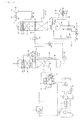
- Fig. 1 shows a combustion exhaust gas treatment system of Embodiment 1 according to the present invention.
- This combustion exhaust gas treatment system is, for example, a part of a power generation plant.
- This combustion exhaust gas treatment system comprises Boiler (Combustion Apparatus) 1, Denitration Device 2, Air Heater 3, Gas Cooler (Heat Exchanger (A)) 4, Electrostatic Precipitator 5, Wet Desulfurization Device 6, Pre-scrubber 10, CO 2 Absorption Column 20, Desorption Column 40, Reboiler 60, Flash Tank 91 and the like.
- Combustion exhaust gas of fossil fuels such as coal and the like discharged from Boiler 1 is passed through Denitration Device 2 to remove nitrogen oxides, and then heat exchanged with air in Air Heater 3 to cool down to, for example, 130 to 220 °C.
- the air heated in Air Heater 3 is supplied to Boiler 1.
- the exhaust gas passed through Air Heater 3 is cooled in Gas Cooler 4, for example, down to about 85 to 100 °C. Heat contained in the exhaust gas is recovered into heat medium in this cooling.
- Sulfur oxide (SO 3 ) in the exhaust gas is absorbed into smoke and dust.
- Electrostatic precipitator 5 removes smoke and dust in the exhaust gas along with SO 3 .
- Pre-scrubber 10 is preferably provided before Absorption Column 20 to minimize residual SO 2 as much as possible (for example, 10 ppm or less).
- CO 2 Absorption Column 20 comprises Packed Bed 21, Absorbent Spray Section 22, Water Washing Section 24, Washing Water Spray Section 25, Demister 26, Washing Water Reservoir 27, Condenser 28, Washing Water Pump 29 and the like.
- Packed Bed 21 CO 2 contained in the exhaust gas is subjected to gas-liquid contacts with CO 2 absorbent supplied from the CO 2 absorbent spray section located at the upper part of the CO 2 Absorption Column 20, and absorbed into the CO 2 absorbent. Heat is generated at the time of CO 2 absorption. The temperature of the CO 2 removed gas (de-CO 2 gas) is increased by this heat.
- Water Washing Section 24 the CO 2 removed gas is cooled and mist coming along with the CO 2 removed gas is removed.
- washing water cooled by Condenser 28 is recirculated for use through Washing Water Pump 29.
- Demister 26 provided above Water Washing Section 24 removes mist which is not able to be removed in the water washing section, and the treated gas (de-CO 2 gas) 37 is discharged.
- Absorbent comprising an amine compound as a main component is preferably used.
- the CO 2 absorbed absorbent is withdrawn from the liquid reservoir at the lower part of Absorption Column 20 by Absorption Column Withdrawal Pump 33, and heated to, for example, 95 to 105 °C in Heat Exchanger 34.
- Heater (Heat Exchanger (B)) 38a is provided in CO 2 Absorbent Supply Line 35 leading to Desorption Column 40.
- the heat source of Heater 38a is heat medium which has recovered heat in Gas Cooler 4.
- the absorbent flowing into the desorption column can be heated to a predetermined temperature (for example, 95 to 105 °C). By this, the consumption of Steam 62 extracted from a turbine system can be reduced, and decrease in power generation efficiency can be suppressed.
- CO 2 enriched absorbent which is sprayed from Spray Section 42 is supplied to Packed Bed 41. Meanwhile, in Reboiler 60 provided at the bottom of Desorption Column 40, absorbent is vaporized by heat supplied via Steam Supply Line 65. In Packed Bed 41, as the CO 2 enriched absorbent is subjected to gas-liquid contacts with absorbent vapor ascending from the bottom, CO 2 is released from the absorbent. Mist of absorbent goes together into the released CO 2 gas, and the mist is removed in Water Washing Section 43. Demister 45 provided above Water Washing Section 43 removes mist which is not able to be removed in the water washing section. CO 2 Gas 46 is discharged from the top of Desorption Column 40.
- This CO 2 gas is cooled down to about 40 °C in Condenser 47 and separated into gas and condensed water in CO 2 Separator 48.
- the CO 2 gas is introduced into a CO 2 liquefying apparatus (not shown) while the condensed water is returned to the washing water spray section by Drain Pump 50.
- the CO 2 released CO 2 absorbent is pooled in Desorption Column Liquid Reservoir 51. Subsequently, it is passed to Reboiler 60 through Reboiler Liquid Supply Line 52. A heat exchanger tube and the like is provided inside Reboiler 60 and CO 2 absorbent is indirectly heated by Steam 62 supplied via the steam supply line such that absorbent vapor is generated inside Reboiler 60 and supplied to Desorption Column 40 via Vapor Supply Line 65. Steam 62 used in Reboiler 60 is returned to drain water in the heat exchanger tube to be collected.
- the vapor recompression apparatus comprising Compressor 92, Line 97 and the like, and Flash Tank 91 are provided.
- CO 2 absorbent pooled in the liquid reservoir at the bottom of Desorption Column 40 is supplied to Flash Tank 91. It is decompressed through Pressure Regulating Valve 67 by taking advantage of a pressurized condition of about 0.1 MPa (g) in Desorption Column 40, and vaporized under reduced pressure in the Flash Tank 91 to generate saturated vapor.
- Compressor 92 serves to recompress the vapor vaporized under reduced pressure in Flash Tank 91 and to transport the vapor to Desorption Column 40.
- the liquid phase in Flash Tank 91 is pressurized with Pump 93 via Flash Tank Outlet Line 96 and cooled by Heat Exchanger 34 and Condenser 31 before supplied to CO 2 Absorption Column 20.
- Embodiment 1 by flash vaporizing absorbent in Flash Tank 91 and heating absorbent in Heater (Heat Exchanger (B)) 38a, the consumption of Steam 62 supplied to Reboiler 60 can be reduced, and decrease in power generation efficiency can be suppressed.
- Heater Heat Exchanger
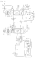
- Fig. 2 shows a combustion exhaust gas treatment system of Embodiment 2 according to the present invention.
- Heater (Heat exchanger (C)) 38b is provided at Outlet Line 96 of Flash Tank 91.
- the heat source of Heater 38b is heat medium which has recovered heat in Gas Cooler 4.
- Regenerated CO 2 absorbent is heated in Heater 38b to a temperature (for example, 130 °C or higher) at which absorbent flowing into the desorption column can be heated by heat exchange in Heat Exchanger 34.
- the absorbent flowing into the desorption column can be easily brought to a predetermined temperature (for example, 95 to 105 °C) in Heat Exchanger 34.
- a predetermined temperature for example, 95 to 105 °C
- Fig. 3 shows a combustion exhaust gas treatment system of Embodiment 3 according to the present invention.
- Gas Reheater (Heat Exchanger (D)) 8 is provided at CO 2 Absorption Column 20.
- Heater (Heat Exchanger (B)) 38a is also provided as in the system shown in Fig. 1 .
- the heat source of Heater 38a and Gas Reheater 8 is heat medium which has recovered heat in Gas Cooler 4.
- CO 2 absorbed absorbent is heated to a predetermined temperature (for example, 95 to 105 °C) by Heater 38a.
- a predetermined temperature for example, 95 to 105 °C
- Heater 38a By this, the consumption of Steam 62 extracted from a turbine system can be reduced, and decrease in power generation efficiency can be suppressed.
- sensible heat recovered in Gas Cooler 4 can be used for reheating CO 2 Removed Gas 37 through heat medium by Gas Reheater 8 provided at the top of Absorption Column 20.
Landscapes
- Chemical & Material Sciences (AREA)
- Engineering & Computer Science (AREA)
- Chemical Kinetics & Catalysis (AREA)
- Analytical Chemistry (AREA)
- General Chemical & Material Sciences (AREA)
- Oil, Petroleum & Natural Gas (AREA)
- Biomedical Technology (AREA)
- Health & Medical Sciences (AREA)
- Environmental & Geological Engineering (AREA)
- Organic Chemistry (AREA)
- Inorganic Chemistry (AREA)
- Combustion & Propulsion (AREA)
- Mechanical Engineering (AREA)
- General Engineering & Computer Science (AREA)
- Treating Waste Gases (AREA)
- Gas Separation By Absorption (AREA)
- Carbon And Carbon Compounds (AREA)
Abstract
Description
- The present invention relates to a combustion exhaust gas treatment system and a method of treating combustion exhaust gas to absorb and separate carbon dioxide (CO2) in combustion exhaust gas of fossil fuel and the like. More specifically, the present invention relates to a combustion exhaust gas treatment system and a method of treating combustion exhaust gas having a high degree of freedom in plant design as well as high thermal efficiency and high CO2 removal capability.
- In thermal power generation facilities and boiler equipment, a large amount of fuels such as coal and heavy oil are burned, generating a large amount of carbon dioxide. In recent years, it has been proposed that discharge of carbon dioxide (CO2) should be globally controlled in view of air pollution and global warming. As one of the techniques for separation and recovery of CO2, known is a method of absorbing CO2 into absorbent such as an amine compound, i.e., a chemical absorption method. This chemical absorption method requires a large amount of thermal energy. In the chemical absorption method, among total energy generated from combustion, energy that can be used for the original purposes such as power generation will be decreased, resulting in reduction of power generation efficiency. From an economical point of view, it is important to suppress the decrease in power generation efficiency to effectively utilize the thermal energy in equipment where the chemical absorption method is used.
- As an approach for increasing thermal efficiency, for example,
Patent Literature 1 discloses a method of purifying combustion exhaust gas comprising: contacting the combustion exhaust gas with absorbent in a CO2 absorption column to absorb CO2 in the combustion exhaust gas into the absrobent, the absorbent comprising an aqueous alkanolamine solution; applying heat contained in the combustion exhaust gas and heat of condensation of liquid vapor in the combustion gas to the CO2 absorbed absorbent in a heat exchanger; heating the CO2 absorbed absorbent in a desorption column and releasing CO2 to regenerate the absorbent and then circulating the regenerated absorbent to the CO2 absorption column. - Further, in the section of BACKGROUND ART and Fig. 7 of
Patent Literature 1, disclosed is a combustion exhaust gas purifying equipment comprising a boiler, an electrostatic precipitator, a blower, a desulfurization device, a CO2 absorption column, a CO2 releasing desorption column and the like, wherein a gas/gas heater is provided between a line connecting the blower and the desulfurization device and a line connecting the absorption column and a chimney. - Further,
Patent Literature 2 discloses flue gas treatment equipment in which a dust precipitator and a desulfurization device for treating smoke, dust and sulfur oxides contained in exhaust gas from a boiler are arranged in sequence from the upstream of an exhaust gas flow line, comprising a heat recovery device provided at the exhaust gas flow line between the precipitator and the desulfurization device, and a feed water line for supplying water to the boiler and a feed water heater provided at the feed water line, and an interconnecting line for heat medium circulation interconnecting the heat recovery device and the feed water heater. - Patent Literature 1:
JP H7-241440 A - Patent Literature 2:
JP 2001-239129 A - The equipment according to
Patent Literature 1 has high thermal efficiency and high removal capability. Nonetheless, there is limitation in arrangement of each device because a plurality of heat exchangers need to be provided in the middle of the line transporting absorbent from the CO2 absorption column to the desorption column. A material having resistance to both combustion exhaust gas and absorbent has to be selected for use in the heat exchangers. Therefore, the degree of freedom in plant design is low. In addition, further improvement of thermal efficiency is demanded in view of improving power generation efficiency. - An object of the present invention is to provide a combustion exhaust gas treatment system and a method of treating combustion exhaust gas, having a high degree of freedom in plant design as well as high thermal efficiency and high removal capability. Another object of the present invention is to provide a combustion exhaust gas treatment system and a method of treating combustion exhaust gas, wherein decrease in temperature of CO2 absorbent supplied to a desorption column can be prevented, the consumption of steam extracted from a turbine system can be reduced, and decrease in power generation efficiency can be suppressed.
- The present inventors have tried to improve the system shown in Fig. 7 of
Patent Literature 1 in order to achieve the above objects.Fig. 4 shows the improved system. The system shown inFig. 4 is provided with a flash tank and a vapor recompression apparatus below a desorption column. CO2 absorbent pooled in a liquid reservoir at the bottom ofDesorption Column 40 can be supplied to FlashTank 91, decompressed through Pressure Regulating Valve 67 by taking advantage of a pressurized condition of about 0.1 MPa (g) inDesorption Column 40, and vaporized under reduced pressure in FlashTank 91 to generate saturated vapor.Compressor 92 serves to recompress the vapor vaporized under reduced pressure in Flash Tank 91 and to transport the vapor to Desorption Column 40. A liquid phase in Flash Tank 91 is pressurized with Pump 93 via Flash Tank Outlet Line 96 and cooled by Heat Exchanger 34 andCondenser 31 before supplied to CO2 Absorption Column 20. It appears that Steam 62 to be supplied to Reboiler 60 can be reduced since absorbent vapor can be passed to the desorption column through the flash tank and the vapor recompression apparatus. When the pressure of Flash Tank 91 is controlled to be near the normal pressure (0 MPa (g)) byPressure Gage 68 and Pressure Regulating Valve 67, heat is used most efficiently. However, when operated under this condition, the temperature of CO2 absorbent in Flash Tank 91 is decreased to, for example, about 100 to 105 °C. When the temperature of absorbent from the flash tank is decreased, heat exchange inHeat Exchanger 34 of normal size alone may not maintain the temperature of CO2 absorbent at the inlet ofDesorption Column 40 at a predetermined temperature (for example, 95 to 105 °C). Decrease in the temperature of absorbent which flows into the desorption column reduces calorific value supplied toDesorption Column 40. As a result, the flow rate of Steam 62 to Reboiler 60 has to be increased. In order to maintain absorbent which flows into the desorption column at predetermined temperature, a very large heat transfer area is required for Heat Exchanger 34, which leads to a significant economic disadvantage. - Accordingly, after additional studies, the present inventors have completed the invention having the following aspects.
- [1] A combustion exhaust gas treatment system comprising: a combustion apparatus, a heat exchanger (A) for recovering heat contained in gas discharged from the combustion apparatus into heat medium, an absorption column for obtaining CO2 removed gas by contacting the exhaust gas with absorbent to absorb CO2 in the exhaust gas into the absorbent, a desorption column for regenerating the absorbent by releasing CO2 from the CO2 absorbed absorbent, a reboiler for vaporizing the absorbent to supply heat to the desorption column, a flash tank for flash vaporizing the regenerated absorbent, and a heat exchanger (E) for transferring heat from the regenerated absorbent to the CO2 absorbed absorbent; the CO2 absorbed absorbent being able to be supplied from the absorption column to the desorption column via the heat exchanger (E), and the regenerated absorbent being able to be supplied from the desorption column to the absorption column via the flash tank and the heat exchanger (E) in this order, wherein the system further comprises a heat exchanger (B) provided between the heat exchanger (E) and the desorption column to apply the heat recovered by the heat medium to the CO2 absorbed absorbent and/or a heat exchanger (C) provided between the flash tank and the heat exchanger (E) to apply the heat recovered by the heat medium to the desorbed absorbent.
- [2] The combustion exhaust gas treatment system according to [1], further comprising a heat exchanger (D) for applying the heat recovered by the heat medium to the CO2 removed gas.
- [3] The combustion exhaust gas treatment system according to [1] or [2], further comprising a vapor recompression apparatus for compressing vapor withdrawn from an upper part of the flash tank to be fed to the desorption column.
- [4] The combustion exhaust gas treatment system according to any one of [1] to [3], further comprising a wet flue gas desulfurization device provided between the heat exchanger (A) and the absorption column to remove sulfur oxides in the exhaust gas.
- [5] The combustion exhaust gas treatment system according to any one of [1] to [4], further comprising a denitration device provided between the combustion apparatus and the heat exchanger (A) to remove nitrogen oxides in the exhaust gas.
- [6] The combustion exhaust gas treatment system according to any one of [1] to [5], wherein the absorbent comprises an amine compound as a main component.
- [7] A method of treating combustion exhaust gas, the method comprising the steps of: recovering heat contained in the combustion exhaust gas into heat medium in the heat exchanger (A), obtaining CO2 removed gas by contacting the combustion exhaust gas with absorbent to absorb CO2 in the combustion exhaust gas into the absorbent, releasing CO2 from the CO2 absorbed absorbent to regenerate the absorbent, flash vaporizing the regenerated absorbent, and performing heat exchange between the flash vaporized absorbent and the CO2 absorbed absorbent in the heat exchanger (E), wherein the method further comprises the steps of: performing heat exchange in the heat exchanger (E) and then applying the heat recovered by the heat medium to the CO2 absorbed absorbent in the heat exchanger (B); and/or applying the heat recovered by the heat medium to the flash vaporized absorbent in the heat exchanger (C) before performing heat exchange in the heat exchanger (E).
- [8] The method of treating combustion exhaust gas according to [7], further comprising the step of applying the heat recovered by the heat medium to the CO2 removed gas in the heat exchanger (D).
- The combustion exhaust gas treatment system or the method of treating combustion exhaust gas according to the present invention has a high degree of freedom in plant design as well as high thermal efficiency and high CO2 removal capability. In addition, according to the present invention, the consumption of Steam 62 extracted from a turbine system can be reduced, and decrease in power generation efficiency can be suppressed by heating CO2 absorbent with sensible heat recovered from exhaust gas in Gas Cooler 4 through heat medium in
Heater 38a or 38b provided in a CO2 absorbent line at an inlet or outlet ofDesorption Column 40 and increasing calorific value to be supplied toDesorption Column 40. -
-
Fig. 1 shows a combustion exhaust gas treatment system ofEmbodiment 1 according to the present invention. - Fig. 2 shows a combustion exhaust gas treatment system of
Embodiment 2 according to the present invention. -
Fig. 3 shows a combustion exhaust gas treatment system ofEmbodiment 3 according to the present invention. -
Fig. 4 shows a combustion exhaust gas treatment system that the present inventors examined first. - Referring to the drawings, the embodiments according to the present invention will be described below. It should be understood that the present invention is not limited to the embodiments described below, and that modification, addition or omission can be made without departing from the object or the spirit of the present invention.
-
Fig. 1 shows a combustion exhaust gas treatment system ofEmbodiment 1 according to the present invention. This combustion exhaust gas treatment system is, for example, a part of a power generation plant. This combustion exhaust gas treatment system comprises Boiler (Combustion Apparatus) 1,Denitration Device 2,Air Heater 3, Gas Cooler (Heat Exchanger (A)) 4,Electrostatic Precipitator 5,Wet Desulfurization Device 6, Pre-scrubber 10, CO2 Absorption Column 20,Desorption Column 40,Reboiler 60, FlashTank 91 and the like. - Combustion exhaust gas of fossil fuels such as coal and the like discharged from
Boiler 1 is passed throughDenitration Device 2 to remove nitrogen oxides, and then heat exchanged with air inAir Heater 3 to cool down to, for example, 130 to 220 °C. The air heated inAir Heater 3 is supplied toBoiler 1. The exhaust gas passed throughAir Heater 3 is cooled in Gas Cooler 4, for example, down to about 85 to 100 °C. Heat contained in the exhaust gas is recovered into heat medium in this cooling. Sulfur oxide (SO3) in the exhaust gas is absorbed into smoke and dust.Electrostatic precipitator 5 removes smoke and dust in the exhaust gas along with SO3. Then, it is pressurized with an induced draft fan, and sulfur oxide (SO2) is removed inWet Desulfurization Device 6. About 10 ppm of SO2 usually remains in outlet gas fromWet Desulfurization Device 6. This residual SO2 may deteriorate CO2 absorbent in CO2 Absorption Column 20. In order to prevent this, Pre-scrubber 10 is preferably provided beforeAbsorption Column 20 to minimize residual SO2 as much as possible (for example, 10 ppm or less). - CO2 Absorption Column 20 comprises Packed
Bed 21, Absorbent Spray Section 22,Water Washing Section 24, WashingWater Spray Section 25,Demister 26,Washing Water Reservoir 27,Condenser 28,Washing Water Pump 29 and the like. InPacked Bed 21, CO2 contained in the exhaust gas is subjected to gas-liquid contacts with CO2 absorbent supplied from the CO2 absorbent spray section located at the upper part of the CO2 Absorption Column 20, and absorbed into the CO2 absorbent. Heat is generated at the time of CO2 absorption. The temperature of the CO2 removed gas (de-CO2 gas) is increased by this heat. InWater Washing Section 24, the CO2 removed gas is cooled and mist coming along with the CO2 removed gas is removed. Further, washing water cooled byCondenser 28 is recirculated for use throughWashing Water Pump 29.Demister 26 provided aboveWater Washing Section 24 removes mist which is not able to be removed in the water washing section, and the treated gas (de-CO2 gas) 37 is discharged. Absorbent comprising an amine compound as a main component is preferably used. - The CO2 absorbed absorbent is withdrawn from the liquid reservoir at the lower part of
Absorption Column 20 by AbsorptionColumn Withdrawal Pump 33, and heated to, for example, 95 to 105 °C inHeat Exchanger 34. In the embodiment according to the present invention shown inFig. 1 , Heater (Heat Exchanger (B)) 38a is provided in CO2Absorbent Supply Line 35 leading toDesorption Column 40. The heat source ofHeater 38a is heat medium which has recovered heat in Gas Cooler 4. WithHeater 38a, the absorbent flowing into the desorption column can be heated to a predetermined temperature (for example, 95 to 105 °C). By this, the consumption ofSteam 62 extracted from a turbine system can be reduced, and decrease in power generation efficiency can be suppressed. - In
Desorption Column 40, CO2 enriched absorbent which is sprayed fromSpray Section 42 is supplied to PackedBed 41. Meanwhile, inReboiler 60 provided at the bottom ofDesorption Column 40, absorbent is vaporized by heat supplied viaSteam Supply Line 65. InPacked Bed 41, as the CO2 enriched absorbent is subjected to gas-liquid contacts with absorbent vapor ascending from the bottom, CO2 is released from the absorbent. Mist of absorbent goes together into the released CO2 gas, and the mist is removed inWater Washing Section 43.Demister 45 provided aboveWater Washing Section 43 removes mist which is not able to be removed in the water washing section. CO2 Gas 46 is discharged from the top ofDesorption Column 40. This CO2 gas is cooled down to about 40 °C inCondenser 47 and separated into gas and condensed water in CO2 Separator 48. The CO2 gas is introduced into a CO2 liquefying apparatus (not shown) while the condensed water is returned to the washing water spray section byDrain Pump 50. - Meanwhile, the CO2 released CO2 absorbent is pooled in Desorption
Column Liquid Reservoir 51. Subsequently, it is passed to Reboiler 60 through ReboilerLiquid Supply Line 52. A heat exchanger tube and the like is provided insideReboiler 60 and CO2 absorbent is indirectly heated bySteam 62 supplied via the steam supply line such that absorbent vapor is generated insideReboiler 60 and supplied toDesorption Column 40 viaVapor Supply Line 65.Steam 62 used inReboiler 60 is returned to drain water in the heat exchanger tube to be collected. - In
Embodiment 1, the vapor recompressionapparatus comprising Compressor 92,Line 97 and the like, andFlash Tank 91 are provided. CO2 absorbent pooled in the liquid reservoir at the bottom ofDesorption Column 40 is supplied toFlash Tank 91. It is decompressed throughPressure Regulating Valve 67 by taking advantage of a pressurized condition of about 0.1 MPa (g) inDesorption Column 40, and vaporized under reduced pressure in theFlash Tank 91 to generate saturated vapor.Compressor 92 serves to recompress the vapor vaporized under reduced pressure inFlash Tank 91 and to transport the vapor toDesorption Column 40. The liquid phase inFlash Tank 91 is pressurized withPump 93 via FlashTank Outlet Line 96 and cooled byHeat Exchanger 34 andCondenser 31 before supplied to CO2 Absorption Column 20. - In
Embodiment 1, by flash vaporizing absorbent inFlash Tank 91 and heating absorbent in Heater (Heat Exchanger (B)) 38a, the consumption ofSteam 62 supplied to Reboiler 60 can be reduced, and decrease in power generation efficiency can be suppressed. - Fig. 2 shows a combustion exhaust gas treatment system of
Embodiment 2 according to the present invention. - In the system shown in Fig. 2, Heater (Heat exchanger (C)) 38b is provided at
Outlet Line 96 ofFlash Tank 91. The heat source of Heater 38b is heat medium which has recovered heat in Gas Cooler 4. Regenerated CO2 absorbent is heated in Heater 38b to a temperature (for example, 130 °C or higher) at which absorbent flowing into the desorption column can be heated by heat exchange inHeat Exchanger 34. Then the absorbent flowing into the desorption column can be easily brought to a predetermined temperature (for example, 95 to 105 °C) inHeat Exchanger 34. As a result, the consumption ofSteam 62 extracted from a turbine system can be reduced, and decrease in power generation efficiency can be suppressed. -
Fig. 3 shows a combustion exhaust gas treatment system ofEmbodiment 3 according to the present invention. - In the system shown in
Fig. 3 , Gas Reheater (Heat Exchanger (D)) 8 is provided at CO2 Absorption Column 20. Heater (Heat Exchanger (B)) 38a is also provided as in the system shown inFig. 1 . The heat source ofHeater 38a andGas Reheater 8 is heat medium which has recovered heat in Gas Cooler 4. CO2 absorbed absorbent is heated to a predetermined temperature (for example, 95 to 105 °C) byHeater 38a. By this, the consumption ofSteam 62 extracted from a turbine system can be reduced, and decrease in power generation efficiency can be suppressed. Further, sensible heat recovered in Gas Cooler 4 can be used for reheating CO2 RemovedGas 37 through heat medium byGas Reheater 8 provided at the top ofAbsorption Column 20. -
- 1:
- Boiler; 2: Denitration Device; 3: Air Heater;
- 4:
- Gas Cooler (Heat Exchanger (A));
- 5:
- Dry Electrostatic Precipitator;
- 6:
- Wet Desulfurization Device;
- 7:
- Desulfurization Outlet Exhaust Gas;
- 8:
- Gas Reheater (Heat Exchanger (D));
- 10:
- Pre-scrubber; 11: Absorbent;
- 12:
- Liquid Reservoir; 14: Circulating Pump;
- 15:
- Condenser; 16: Spray Section; 17: Cooling Water;
- 18:
- Pre-scrubber Outlet Gas; 20: Absorption Column;
- 21:
- Packed Bed; 22: Absorbent Spray Section;
- 23:
- De-CO2 Gas; 24: Water Washing Section;
- 25:
- Washing Water Spray Section; 26: Demister;
- 27:
- Absorption Column Washing Water Reservoir;
- 28:
- Condenser; 29: Washing Water Pump;
- 30:
- Cooling Water; 31: Condenser; 32: Boiler Water;
- 33:
- Absorption Column Withdrawal Pump;
- 34:
- Heat Exchanger (E);
- 35:
- Desorption Column Liquid Supply Line;
- 36:
- Washing Water Withdrawal Line; 37: Treated Gas;
- 38a:
- Amine Heater (Heat Exchanger (B));
- 38b:
- Amine Heater (Heat Exchanger (C));
- 40:
- Desorption Column; 41: Packed Bed;
- 42:
- Spray Section; 43: Water Washing Section;
- 44:
- Washing Water Spray Section; 45: Demister;
- 46:
- CO2 Gas; 47: Condenser; 48: CO2 Separator;
- 49:
- Drain Line; 50: Drain Pump;
- 51:
- Desorption Column Liquid Reservoir;
- 52:
- Reboiler Liquid Supply Line; 60: Reboiler;
- 61:
- Steam Supply Line; 62: Steam;
- 63:
- Reboiler Liquid Reservoir;
- 64:
- Reboiler Liquid Withdrawal Line;
- 65:
- Vapor Supply Line;
- 66:
- Desorption Column Liquid Withdrawal Line;
- 67:
- Pressure Regulating Valve; 68: Pressure Gage;
- 91:
- Flash Tank; 92: Compressor; 93: Pump;
- 96:
- CO2 Absorbent Supply Line; 97: Vapor Line;
Claims (8)
- A combustion exhaust gas treatment system comprising:a combustion apparatus,a heat exchanger (A) for recovering heat contained in gas discharged from the combustion apparatus into heat medium,an absorption column for obtaining CO2 removed gas by contacting the exhaust gas with absorbent to absorb CO2 in the exhaust gas into the absorbent,a desorption column for regenerating the absorbent by releasing CO2 from the CO2 absorbed absorbent,a reboiler for vaporizing the absorbent to supply heat to the desorption column,a flash tank for flash vaporizing the regenerated absorbent anda heat exchanger (E) for transferring heat from the regenerated absorbent to the CO2 absorbed absorbent;the CO2 absorbed absorbent being able to be supplied from the absorption column to the desorption column via the heat exchanger (E), and the regenerated absorbent being able to be supplied from the desorption column to the absorption column via the flash tank and the heat exchanger (E) in this order,wherein the system further comprises a heat exchanger (B) provided between the heat exchanger (E) and the desorption column to apply the heat recovered by the heat medium to the CO2 absorbed absorbent and/ora heat exchanger (C) provided between the flash tank and the heat exchanger (E) to apply the heat recovered by the heat medium to the desorbed absorbent.
- The combustion exhaust gas treatment system according to claim 1, further comprising a heat exchanger (D) for applying the heat recovered by the heat medium to the CO2 removed gas.
- The combustion exhaust gas treatment system according to claim 1 or 2, further comprising a vapor recompression apparatus for compressing vapor withdrawn from an upper part of the flash tank to be fed to the desorption column.
- The combustion exhaust gas treatment system according to any one of claims 1 to 3, further comprising a wet flue gas desulfurization device provided between the heat exchanger (A) and the absorption column to remove sulfur oxides in the exhaust gas.
- The combustion exhaust gas treatment system according to any one of claims 1 to 4, further comprising a denitration device provided between the combustion apparatus and the heat exchanger (A) to remove nitrogen oxides in the exhaust gas.
- The combustion exhaust gas treatment system according to any one of claims 1 to 5, wherein the absorbent comprises an amine compound as a main component.
- A method of treating combustion exhaust gas, the method comprising the steps of: recovering heat contained in the combustion exhaust gas into heat medium in the heat exchanger (A),
obtaining CO2 removed gas by contacting the combustion exhaust gas with absorbent to absorb CO2 in the combustion exhaust gas into the absorbent,
releasing CO2 from the CO2 absorbed absorbent to regenerate the absorbent,
flash vaporizing the regenerated absorbent,
performing heat exchange between the flash vaporized absorbent and the CO2 absorbed absorbent in the heat exchanger (E),
wherein the method further comprises the steps of:performing heat exchange in the heat exchanger (E) andthen applying the heat recovered by the heat medium to the CO2 absorbed absorbent in the heat exchanger (B);and/or applying the heat recovered by the heat medium to the flash vaporized absorbent in the heat exchanger (C) before performing heat exchange in the heat exchanger (E). - The method of treating combustion exhaust gas according to claim 7, further comprising the step of applying the heat recovered by the heat medium to the CO2 removed gas in the heat exchanger (D).
Priority Applications (1)
| Application Number | Priority Date | Filing Date | Title |
|---|---|---|---|
| PL12802467T PL2722097T3 (en) | 2011-06-20 | 2012-06-19 | Combustion exhaust gas treatment system and combustion exhaust gas treatment method |
Applications Claiming Priority (2)
| Application Number | Priority Date | Filing Date | Title |
|---|---|---|---|
| JP2011136110A JP5725992B2 (en) | 2011-06-20 | 2011-06-20 | CO2 recovery equipment |
| PCT/JP2012/003974 WO2012176430A1 (en) | 2011-06-20 | 2012-06-19 | Combustion exhaust gas treatment system and combustion exhaust gas treatment method |
Publications (3)
| Publication Number | Publication Date |
|---|---|
| EP2722097A1 true EP2722097A1 (en) | 2014-04-23 |
| EP2722097A4 EP2722097A4 (en) | 2015-03-18 |
| EP2722097B1 EP2722097B1 (en) | 2018-11-21 |
Family
ID=47422288
Family Applications (1)
| Application Number | Title | Priority Date | Filing Date |
|---|---|---|---|
| EP12802467.6A Active EP2722097B1 (en) | 2011-06-20 | 2012-06-19 | Combustion exhaust gas treatment system and combustion exhaust gas treatment method |
Country Status (7)
| Country | Link |
|---|---|
| US (1) | US9399939B2 (en) |
| EP (1) | EP2722097B1 (en) |
| JP (1) | JP5725992B2 (en) |
| CN (1) | CN103561848A (en) |
| CA (1) | CA2824740C (en) |
| PL (1) | PL2722097T3 (en) |
| WO (1) | WO2012176430A1 (en) |
Families Citing this family (26)
| Publication number | Priority date | Publication date | Assignee | Title |
|---|---|---|---|---|
| JP5901296B2 (en) | 2012-01-06 | 2016-04-06 | 三菱日立パワーシステムズ株式会社 | CO2 chemical absorption system |
| JP2014132250A (en) | 2013-01-07 | 2014-07-17 | Toyota Motor Corp | Radar device |
| US9504957B2 (en) * | 2014-01-06 | 2016-11-29 | University Of Kentucky Research Foundation | Flue gas desulfurization apparatus |
| AU2015243729A1 (en) * | 2014-04-07 | 2016-09-29 | Siemens Aktiengesellschaft | Device and method for separating carbon dioxide from a gas stream, in particular from a flue gas stream, comprising a cooling water system |
| CN104031711A (en) * | 2014-06-28 | 2014-09-10 | 辽宁石油化工大学 | Natural gas pretreatment method and device through combined cooling heating and power |
| KR101630054B1 (en) * | 2014-08-04 | 2016-06-13 | 한국전력공사 | System for collecting acid gas and method for collecting the same |
| CN104296543A (en) * | 2014-09-24 | 2015-01-21 | 中科苏派能源科技靖江有限公司 | Denitration and waste heat recovery integrated furnace |
| CN104307310A (en) * | 2014-11-07 | 2015-01-28 | 清本环保工程(杭州)有限公司 | Gas treatment system and method in photosensory membrane printing |
| JP6392099B2 (en) | 2014-12-01 | 2018-09-19 | 株式会社東芝 | Carbon dioxide recovery system |
| US10375901B2 (en) | 2014-12-09 | 2019-08-13 | Mtd Products Inc | Blower/vacuum |
| JP6345127B2 (en) * | 2015-01-22 | 2018-06-20 | 三菱重工業株式会社 | Exhaust gas treatment system and method |
| US11612851B2 (en) | 2017-04-13 | 2023-03-28 | The Kansai Electric Power Co., Inc. | Carbon dioxide recovery system and carbon dioxide recovery method |
| CN107626185B (en) * | 2017-10-10 | 2019-11-08 | 华中科技大学 | A carbon capture system for supercritical carbon dioxide coal-fired power plants |
| US11224837B2 (en) * | 2018-11-12 | 2022-01-18 | Linde Aktiengesellschaft | Post-combustion carbon dioxide capture and compression |
| US11484825B1 (en) * | 2021-12-20 | 2022-11-01 | Next Carbon Solutions, Llc | Devices, systems, facilities and processes for carbon capture optimization in industrial facilities |
| CN114307577A (en) * | 2021-12-30 | 2022-04-12 | 山东大学 | A system and process for obtaining heat from flue gas by using desulfurization pretreatment |
| KR102753647B1 (en) | 2022-04-20 | 2025-01-14 | 한국전력공사 | Acid gas capture system by heat exchange optimization and method for acid gas capture using thereof |
| CN115463521A (en) * | 2022-05-31 | 2022-12-13 | 华能营口热电有限责任公司 | A low energy consumption carbon capture device and method |
| JP7309983B1 (en) * | 2022-08-08 | 2023-07-18 | 株式会社タクマ | Carbon dioxide recovery device and carbon dioxide recovery method |
| CN115738601A (en) * | 2022-12-01 | 2023-03-07 | 安徽普泛能源技术有限公司 | Gas removing and pressure increasing equipment and process |
| KR102815668B1 (en) * | 2022-12-06 | 2025-06-02 | 에스케이이노베이션 주식회사 | Method for preventing solvent solidification using carbon dioxide |
| KR102815664B1 (en) * | 2022-12-06 | 2025-06-02 | 에스케이이노베이션 주식회사 | System for preventing solvent solidification using waste heat |
| GB2627940A (en) * | 2023-03-08 | 2024-09-11 | Equinor Low Carbon Uk Ltd | Improvements to energy performance in C02 capture |
| WO2024201895A1 (en) * | 2023-03-30 | 2024-10-03 | 三菱重工業株式会社 | Carbon dioxide recovery system |
| WO2025136365A1 (en) * | 2023-12-19 | 2025-06-26 | Ge Infrastructure Technology Llc | System and method having waste heat recovery for gas capture system |
| CN119733335B (en) * | 2025-01-10 | 2026-01-06 | 华能陇东能源有限责任公司正宁电厂 | An integrated system for capturing carbon dioxide from flue gas |
Family Cites Families (17)
| Publication number | Priority date | Publication date | Assignee | Title |
|---|---|---|---|---|
| JPS5926926A (en) * | 1982-07-30 | 1984-02-13 | Hitachi Zosen Corp | Apparatus for removing co2 with hot potassium carbonate |
| DE69318433T2 (en) * | 1992-01-17 | 1998-12-17 | Mitsubishi Jukogyo K.K., Tokio/Tokyo | Processes for the treatment of combustion gases |
| JP3486220B2 (en) * | 1994-03-08 | 2004-01-13 | バブコック日立株式会社 | Combustion exhaust gas purification method and apparatus |
| JP4725985B2 (en) | 2000-03-03 | 2011-07-13 | バブコック日立株式会社 | Operation method of flue gas treatment equipment |
| US7976803B2 (en) | 2005-08-16 | 2011-07-12 | Co2Crc Technologies Pty Ltd. | Plant and process for removing carbon dioxide from gas streams |
| CA2632425A1 (en) | 2005-12-19 | 2007-07-05 | Fluor Technologies Corporation | Integrated compressor/stripper configurations and methods |
| NO333560B1 (en) * | 2006-11-24 | 2013-07-08 | Aker Clean Carbon As | Method and regenerator for regeneration of liquid CO2 absorbent. |
| US7819951B2 (en) * | 2007-01-23 | 2010-10-26 | Air Products And Chemicals, Inc. | Purification of carbon dioxide |
| NO336193B1 (en) * | 2007-09-14 | 2015-06-08 | Aker Engineering & Technology | Improved method of absorbent regeneration |
| JP2009247932A (en) * | 2008-04-02 | 2009-10-29 | Chiyoda Kako Kensetsu Kk | Method for removing carbon dioxide using exhaust gas heat source |
| JP4956519B2 (en) * | 2008-10-06 | 2012-06-20 | 株式会社東芝 | Carbon dioxide recovery system |
| JP5178453B2 (en) * | 2008-10-27 | 2013-04-10 | 株式会社日立製作所 | Oxyfuel boiler and control method for oxygen fired boiler |
| CN101422691B (en) * | 2008-11-20 | 2011-12-07 | 武汉凯迪电力环保有限公司 | Multi-pollutant removing technique and device of fuel coal smoke |
| CN101637694B (en) * | 2009-05-08 | 2011-09-21 | 北京化工大学 | Method for separating and recycling CO2 from mixed gas containing CO2 |
| JP5350935B2 (en) * | 2009-08-06 | 2013-11-27 | バブコック日立株式会社 | CO2 recovery device exhaust gas treatment method |
| JP5369048B2 (en) * | 2010-05-12 | 2013-12-18 | バブコック日立株式会社 | Exhaust gas treatment system and method having carbon dioxide chemical absorption equipment |
| CN101856579B (en) * | 2010-06-02 | 2012-11-14 | 清华大学 | A new energy-saving CO2 capture process with improved potassium carbonate |
-
2011
- 2011-06-20 JP JP2011136110A patent/JP5725992B2/en active Active
-
2012
- 2012-06-19 CA CA2824740A patent/CA2824740C/en active Active
- 2012-06-19 WO PCT/JP2012/003974 patent/WO2012176430A1/en not_active Ceased
- 2012-06-19 CN CN201280025745.2A patent/CN103561848A/en active Pending
- 2012-06-19 EP EP12802467.6A patent/EP2722097B1/en active Active
- 2012-06-19 PL PL12802467T patent/PL2722097T3/en unknown
- 2012-06-19 US US14/001,068 patent/US9399939B2/en active Active
Also Published As
| Publication number | Publication date |
|---|---|
| US20130327025A1 (en) | 2013-12-12 |
| CA2824740A1 (en) | 2012-12-27 |
| CN103561848A (en) | 2014-02-05 |
| EP2722097B1 (en) | 2018-11-21 |
| PL2722097T3 (en) | 2019-05-31 |
| JP5725992B2 (en) | 2015-05-27 |
| EP2722097A4 (en) | 2015-03-18 |
| CA2824740C (en) | 2019-09-24 |
| US9399939B2 (en) | 2016-07-26 |
| JP2013000694A (en) | 2013-01-07 |
| WO2012176430A1 (en) | 2012-12-27 |
Similar Documents
| Publication | Publication Date | Title |
|---|---|---|
| US9399939B2 (en) | Combustion exhaust gas treatment system and method of treating combustion exhaust gas | |
| JP5465246B2 (en) | Method and apparatus for separating carbon dioxide from exhaust gas from fossil fuel power plant equipment | |
| JP5639814B2 (en) | Thermal power generation system with CO2 removal equipment | |
| JP5738137B2 (en) | CO2 recovery apparatus and CO2 recovery method | |
| US9138677B2 (en) | Ammonia stripper for a carbon capture system for reduction of energy consumption | |
| JP5855130B2 (en) | Carbon dioxide chemical absorption system with steam recompression equipment | |
| JP5959882B2 (en) | Carbon dioxide chemical absorption system in combustion exhaust gas | |
| CA2877852C (en) | Exhaust gas treatment system | |
| JP2011240321A (en) | Exhaust gas treatment system having carbon dioxide removal device | |
| JP2013059726A (en) | Co2 recovery device and co2 recovery method | |
| JP6088240B2 (en) | Carbon dioxide recovery device and method of operating the recovery device | |
| JP2011194292A (en) | Method and apparatus for treating exhaust gas | |
| WO2012073553A1 (en) | Co2 recovery system | |
| WO2012073552A1 (en) | Co2 recovery system | |
| CA2810138C (en) | Exhaust gas treatment system |
Legal Events
| Date | Code | Title | Description |
|---|---|---|---|
| PUAI | Public reference made under article 153(3) epc to a published international application that has entered the european phase |
Free format text: ORIGINAL CODE: 0009012 |
|
| 17P | Request for examination filed |
Effective date: 20131031 |
|
| AK | Designated contracting states |
Kind code of ref document: A1 Designated state(s): AL AT BE BG CH CY CZ DE DK EE ES FI FR GB GR HR HU IE IS IT LI LT LU LV MC MK MT NL NO PL PT RO RS SE SI SK SM TR |
|
| DAX | Request for extension of the european patent (deleted) | ||
| RAP1 | Party data changed (applicant data changed or rights of an application transferred) |
Owner name: BABCOCK-HITACHI KABUSHIKI KAISHA Owner name: MITSUBISHI HITACHI POWER SYSTEMS, LTD. |
|
| A4 | Supplementary search report drawn up and despatched |
Effective date: 20150212 |
|
| RIC1 | Information provided on ipc code assigned before grant |
Ipc: B01D 53/62 20060101AFI20150206BHEP Ipc: B01D 53/14 20060101ALI20150206BHEP Ipc: C01B 31/20 20060101ALI20150206BHEP |
|
| RAP1 | Party data changed (applicant data changed or rights of an application transferred) |
Owner name: MITSUBISHI HITACHI POWER SYSTEMS, LTD. |
|
| RAP1 | Party data changed (applicant data changed or rights of an application transferred) |
Owner name: MITSUBISHI HITACHI POWER SYSTEMS, LTD. |
|
| 17Q | First examination report despatched |
Effective date: 20160808 |
|
| STAA | Information on the status of an ep patent application or granted ep patent |
Free format text: STATUS: EXAMINATION IS IN PROGRESS |
|
| REG | Reference to a national code |
Ref country code: DE Ref legal event code: R079 Ref document number: 602012053856 Country of ref document: DE Free format text: PREVIOUS MAIN CLASS: B01D0053620000 Ipc: B01D0053140000 |
|
| RIC1 | Information provided on ipc code assigned before grant |
Ipc: B01D 53/62 20060101ALI20180413BHEP Ipc: B01D 53/34 20060101ALI20180413BHEP Ipc: C01B 32/50 20170101ALI20180413BHEP Ipc: B01D 53/14 20060101AFI20180413BHEP |
|
| GRAP | Despatch of communication of intention to grant a patent |
Free format text: ORIGINAL CODE: EPIDOSNIGR1 |
|
| STAA | Information on the status of an ep patent application or granted ep patent |
Free format text: STATUS: GRANT OF PATENT IS INTENDED |
|
| INTG | Intention to grant announced |
Effective date: 20180607 |
|
| GRAS | Grant fee paid |
Free format text: ORIGINAL CODE: EPIDOSNIGR3 |
|
| GRAA | (expected) grant |
Free format text: ORIGINAL CODE: 0009210 |
|
| STAA | Information on the status of an ep patent application or granted ep patent |
Free format text: STATUS: THE PATENT HAS BEEN GRANTED |
|
| AK | Designated contracting states |
Kind code of ref document: B1 Designated state(s): AL AT BE BG CH CY CZ DE DK EE ES FI FR GB GR HR HU IE IS IT LI LT LU LV MC MK MT NL NO PL PT RO RS SE SI SK SM TR |
|
| REG | Reference to a national code |
Ref country code: CH Ref legal event code: EP |
|
| REG | Reference to a national code |
Ref country code: IE Ref legal event code: FG4D |
|
| REG | Reference to a national code |
Ref country code: DE Ref legal event code: R096 Ref document number: 602012053856 Country of ref document: DE |
|
| REG | Reference to a national code |
Ref country code: AT Ref legal event code: REF Ref document number: 1066907 Country of ref document: AT Kind code of ref document: T Effective date: 20181215 |
|
| REG | Reference to a national code |
Ref country code: NO Ref legal event code: T2 Effective date: 20181121 |
|
| REG | Reference to a national code |
Ref country code: NL Ref legal event code: MP Effective date: 20181121 |
|
| REG | Reference to a national code |
Ref country code: AT Ref legal event code: MK05 Ref document number: 1066907 Country of ref document: AT Kind code of ref document: T Effective date: 20181121 |
|
| PG25 | Lapsed in a contracting state [announced via postgrant information from national office to epo] |
Ref country code: BG Free format text: LAPSE BECAUSE OF FAILURE TO SUBMIT A TRANSLATION OF THE DESCRIPTION OR TO PAY THE FEE WITHIN THE PRESCRIBED TIME-LIMIT Effective date: 20190221 Ref country code: LT Free format text: LAPSE BECAUSE OF FAILURE TO SUBMIT A TRANSLATION OF THE DESCRIPTION OR TO PAY THE FEE WITHIN THE PRESCRIBED TIME-LIMIT Effective date: 20181121 Ref country code: HR Free format text: LAPSE BECAUSE OF FAILURE TO SUBMIT A TRANSLATION OF THE DESCRIPTION OR TO PAY THE FEE WITHIN THE PRESCRIBED TIME-LIMIT Effective date: 20181121 Ref country code: AT Free format text: LAPSE BECAUSE OF FAILURE TO SUBMIT A TRANSLATION OF THE DESCRIPTION OR TO PAY THE FEE WITHIN THE PRESCRIBED TIME-LIMIT Effective date: 20181121 Ref country code: IS Free format text: LAPSE BECAUSE OF FAILURE TO SUBMIT A TRANSLATION OF THE DESCRIPTION OR TO PAY THE FEE WITHIN THE PRESCRIBED TIME-LIMIT Effective date: 20190321 Ref country code: ES Free format text: LAPSE BECAUSE OF FAILURE TO SUBMIT A TRANSLATION OF THE DESCRIPTION OR TO PAY THE FEE WITHIN THE PRESCRIBED TIME-LIMIT Effective date: 20181121 Ref country code: LV Free format text: LAPSE BECAUSE OF FAILURE TO SUBMIT A TRANSLATION OF THE DESCRIPTION OR TO PAY THE FEE WITHIN THE PRESCRIBED TIME-LIMIT Effective date: 20181121 Ref country code: FI Free format text: LAPSE BECAUSE OF FAILURE TO SUBMIT A TRANSLATION OF THE DESCRIPTION OR TO PAY THE FEE WITHIN THE PRESCRIBED TIME-LIMIT Effective date: 20181121 |
|
| PG25 | Lapsed in a contracting state [announced via postgrant information from national office to epo] |
Ref country code: AL Free format text: LAPSE BECAUSE OF FAILURE TO SUBMIT A TRANSLATION OF THE DESCRIPTION OR TO PAY THE FEE WITHIN THE PRESCRIBED TIME-LIMIT Effective date: 20181121 Ref country code: SE Free format text: LAPSE BECAUSE OF FAILURE TO SUBMIT A TRANSLATION OF THE DESCRIPTION OR TO PAY THE FEE WITHIN THE PRESCRIBED TIME-LIMIT Effective date: 20181121 Ref country code: NL Free format text: LAPSE BECAUSE OF FAILURE TO SUBMIT A TRANSLATION OF THE DESCRIPTION OR TO PAY THE FEE WITHIN THE PRESCRIBED TIME-LIMIT Effective date: 20181121 Ref country code: RS Free format text: LAPSE BECAUSE OF FAILURE TO SUBMIT A TRANSLATION OF THE DESCRIPTION OR TO PAY THE FEE WITHIN THE PRESCRIBED TIME-LIMIT Effective date: 20181121 Ref country code: GR Free format text: LAPSE BECAUSE OF FAILURE TO SUBMIT A TRANSLATION OF THE DESCRIPTION OR TO PAY THE FEE WITHIN THE PRESCRIBED TIME-LIMIT Effective date: 20190222 Ref country code: PT Free format text: LAPSE BECAUSE OF FAILURE TO SUBMIT A TRANSLATION OF THE DESCRIPTION OR TO PAY THE FEE WITHIN THE PRESCRIBED TIME-LIMIT Effective date: 20190321 |
|
| PG25 | Lapsed in a contracting state [announced via postgrant information from national office to epo] |
Ref country code: IT Free format text: LAPSE BECAUSE OF FAILURE TO SUBMIT A TRANSLATION OF THE DESCRIPTION OR TO PAY THE FEE WITHIN THE PRESCRIBED TIME-LIMIT Effective date: 20181121 Ref country code: DK Free format text: LAPSE BECAUSE OF FAILURE TO SUBMIT A TRANSLATION OF THE DESCRIPTION OR TO PAY THE FEE WITHIN THE PRESCRIBED TIME-LIMIT Effective date: 20181121 Ref country code: CZ Free format text: LAPSE BECAUSE OF FAILURE TO SUBMIT A TRANSLATION OF THE DESCRIPTION OR TO PAY THE FEE WITHIN THE PRESCRIBED TIME-LIMIT Effective date: 20181121 |
|
| REG | Reference to a national code |
Ref country code: DE Ref legal event code: R097 Ref document number: 602012053856 Country of ref document: DE |
|
| PG25 | Lapsed in a contracting state [announced via postgrant information from national office to epo] |
Ref country code: RO Free format text: LAPSE BECAUSE OF FAILURE TO SUBMIT A TRANSLATION OF THE DESCRIPTION OR TO PAY THE FEE WITHIN THE PRESCRIBED TIME-LIMIT Effective date: 20181121 Ref country code: SK Free format text: LAPSE BECAUSE OF FAILURE TO SUBMIT A TRANSLATION OF THE DESCRIPTION OR TO PAY THE FEE WITHIN THE PRESCRIBED TIME-LIMIT Effective date: 20181121 Ref country code: EE Free format text: LAPSE BECAUSE OF FAILURE TO SUBMIT A TRANSLATION OF THE DESCRIPTION OR TO PAY THE FEE WITHIN THE PRESCRIBED TIME-LIMIT Effective date: 20181121 Ref country code: SM Free format text: LAPSE BECAUSE OF FAILURE TO SUBMIT A TRANSLATION OF THE DESCRIPTION OR TO PAY THE FEE WITHIN THE PRESCRIBED TIME-LIMIT Effective date: 20181121 |
|
| PLBE | No opposition filed within time limit |
Free format text: ORIGINAL CODE: 0009261 |
|
| STAA | Information on the status of an ep patent application or granted ep patent |
Free format text: STATUS: NO OPPOSITION FILED WITHIN TIME LIMIT |
|
| 26N | No opposition filed |
Effective date: 20190822 |
|
| PG25 | Lapsed in a contracting state [announced via postgrant information from national office to epo] |
Ref country code: SI Free format text: LAPSE BECAUSE OF FAILURE TO SUBMIT A TRANSLATION OF THE DESCRIPTION OR TO PAY THE FEE WITHIN THE PRESCRIBED TIME-LIMIT Effective date: 20181121 |
|
| REG | Reference to a national code |
Ref country code: DE Ref legal event code: R119 Ref document number: 602012053856 Country of ref document: DE |
|
| PG25 | Lapsed in a contracting state [announced via postgrant information from national office to epo] |
Ref country code: MC Free format text: LAPSE BECAUSE OF FAILURE TO SUBMIT A TRANSLATION OF THE DESCRIPTION OR TO PAY THE FEE WITHIN THE PRESCRIBED TIME-LIMIT Effective date: 20181121 |
|
| REG | Reference to a national code |
Ref country code: CH Ref legal event code: PL |
|
| GBPC | Gb: european patent ceased through non-payment of renewal fee |
Effective date: 20190619 |
|
| REG | Reference to a national code |
Ref country code: BE Ref legal event code: MM Effective date: 20190630 |
|
| PG25 | Lapsed in a contracting state [announced via postgrant information from national office to epo] |
Ref country code: TR Free format text: LAPSE BECAUSE OF FAILURE TO SUBMIT A TRANSLATION OF THE DESCRIPTION OR TO PAY THE FEE WITHIN THE PRESCRIBED TIME-LIMIT Effective date: 20181121 |
|
| PG25 | Lapsed in a contracting state [announced via postgrant information from national office to epo] |
Ref country code: DE Free format text: LAPSE BECAUSE OF NON-PAYMENT OF DUE FEES Effective date: 20200101 Ref country code: IE Free format text: LAPSE BECAUSE OF NON-PAYMENT OF DUE FEES Effective date: 20190619 Ref country code: GB Free format text: LAPSE BECAUSE OF NON-PAYMENT OF DUE FEES Effective date: 20190619 |
|
| PG25 | Lapsed in a contracting state [announced via postgrant information from national office to epo] |
Ref country code: BE Free format text: LAPSE BECAUSE OF NON-PAYMENT OF DUE FEES Effective date: 20190630 Ref country code: LI Free format text: LAPSE BECAUSE OF NON-PAYMENT OF DUE FEES Effective date: 20190630 Ref country code: CH Free format text: LAPSE BECAUSE OF NON-PAYMENT OF DUE FEES Effective date: 20190630 Ref country code: LU Free format text: LAPSE BECAUSE OF NON-PAYMENT OF DUE FEES Effective date: 20190619 |
|
| PG25 | Lapsed in a contracting state [announced via postgrant information from national office to epo] |
Ref country code: FR Free format text: LAPSE BECAUSE OF NON-PAYMENT OF DUE FEES Effective date: 20190630 |
|
| REG | Reference to a national code |
Ref country code: NO Ref legal event code: CHAD Owner name: MITSUBISHI POWER, JP |
|
| PG25 | Lapsed in a contracting state [announced via postgrant information from national office to epo] |
Ref country code: CY Free format text: LAPSE BECAUSE OF FAILURE TO SUBMIT A TRANSLATION OF THE DESCRIPTION OR TO PAY THE FEE WITHIN THE PRESCRIBED TIME-LIMIT Effective date: 20181121 |
|
| PG25 | Lapsed in a contracting state [announced via postgrant information from national office to epo] |
Ref country code: HU Free format text: LAPSE BECAUSE OF FAILURE TO SUBMIT A TRANSLATION OF THE DESCRIPTION OR TO PAY THE FEE WITHIN THE PRESCRIBED TIME-LIMIT; INVALID AB INITIO Effective date: 20120619 Ref country code: MT Free format text: LAPSE BECAUSE OF FAILURE TO SUBMIT A TRANSLATION OF THE DESCRIPTION OR TO PAY THE FEE WITHIN THE PRESCRIBED TIME-LIMIT Effective date: 20181121 |
|
| PG25 | Lapsed in a contracting state [announced via postgrant information from national office to epo] |
Ref country code: MK Free format text: LAPSE BECAUSE OF FAILURE TO SUBMIT A TRANSLATION OF THE DESCRIPTION OR TO PAY THE FEE WITHIN THE PRESCRIBED TIME-LIMIT Effective date: 20181121 |
|
| PGFP | Annual fee paid to national office [announced via postgrant information from national office to epo] |
Ref country code: PL Payment date: 20250428 Year of fee payment: 14 |
|
| PGFP | Annual fee paid to national office [announced via postgrant information from national office to epo] |
Ref country code: NO Payment date: 20250610 Year of fee payment: 14 |