EP2721299B1 - Screw type liquid ring pump with integrated macerator - Google Patents
Screw type liquid ring pump with integrated macerator Download PDFInfo
- Publication number
- EP2721299B1 EP2721299B1 EP12800220.1A EP12800220A EP2721299B1 EP 2721299 B1 EP2721299 B1 EP 2721299B1 EP 12800220 A EP12800220 A EP 12800220A EP 2721299 B1 EP2721299 B1 EP 2721299B1
- Authority
- EP
- European Patent Office
- Prior art keywords
- pump
- macerator
- cutter
- rotary cutter
- grinder
- Prior art date
- Legal status (The legal status is an assumption and is not a legal conclusion. Google has not performed a legal analysis and makes no representation as to the accuracy of the status listed.)
- Active
Links
Images


Classifications
-
- B—PERFORMING OPERATIONS; TRANSPORTING
- B02—CRUSHING, PULVERISING, OR DISINTEGRATING; PREPARATORY TREATMENT OF GRAIN FOR MILLING
- B02C—CRUSHING, PULVERISING, OR DISINTEGRATING IN GENERAL; MILLING GRAIN
- B02C18/00—Disintegrating by knives or other cutting or tearing members which chop material into fragments
- B02C18/0084—Disintegrating by knives or other cutting or tearing members which chop material into fragments specially adapted for disintegrating garbage, waste or sewage
- B02C18/0092—Disintegrating by knives or other cutting or tearing members which chop material into fragments specially adapted for disintegrating garbage, waste or sewage for waste water or for garbage
-
- B—PERFORMING OPERATIONS; TRANSPORTING
- B02—CRUSHING, PULVERISING, OR DISINTEGRATING; PREPARATORY TREATMENT OF GRAIN FOR MILLING
- B02C—CRUSHING, PULVERISING, OR DISINTEGRATING IN GENERAL; MILLING GRAIN
- B02C18/00—Disintegrating by knives or other cutting or tearing members which chop material into fragments
- B02C18/06—Disintegrating by knives or other cutting or tearing members which chop material into fragments with rotating knives
-
- B—PERFORMING OPERATIONS; TRANSPORTING
- B02—CRUSHING, PULVERISING, OR DISINTEGRATING; PREPARATORY TREATMENT OF GRAIN FOR MILLING
- B02C—CRUSHING, PULVERISING, OR DISINTEGRATING IN GENERAL; MILLING GRAIN
- B02C19/00—Other disintegrating devices or methods
- B02C19/22—Crushing mills with screw-shaped crushing means
-
- F—MECHANICAL ENGINEERING; LIGHTING; HEATING; WEAPONS; BLASTING
- F01—MACHINES OR ENGINES IN GENERAL; ENGINE PLANTS IN GENERAL; STEAM ENGINES
- F01C—ROTARY-PISTON OR OSCILLATING-PISTON MACHINES OR ENGINES
- F01C21/00—Component parts, details or accessories not provided for in groups F01C1/00 - F01C20/00
- F01C21/08—Rotary pistons
-
- F—MECHANICAL ENGINEERING; LIGHTING; HEATING; WEAPONS; BLASTING
- F04—POSITIVE - DISPLACEMENT MACHINES FOR LIQUIDS; PUMPS FOR LIQUIDS OR ELASTIC FLUIDS
- F04C—ROTARY-PISTON, OR OSCILLATING-PISTON, POSITIVE-DISPLACEMENT MACHINES FOR LIQUIDS; ROTARY-PISTON, OR OSCILLATING-PISTON, POSITIVE-DISPLACEMENT PUMPS
- F04C13/00—Adaptations of machines or pumps for special use, e.g. for extremely high pressures
- F04C13/001—Pumps for particular liquids
-
- F—MECHANICAL ENGINEERING; LIGHTING; HEATING; WEAPONS; BLASTING
- F04—POSITIVE - DISPLACEMENT MACHINES FOR LIQUIDS; PUMPS FOR LIQUIDS OR ELASTIC FLUIDS
- F04C—ROTARY-PISTON, OR OSCILLATING-PISTON, POSITIVE-DISPLACEMENT MACHINES FOR LIQUIDS; ROTARY-PISTON, OR OSCILLATING-PISTON, POSITIVE-DISPLACEMENT PUMPS
- F04C18/00—Rotary-piston pumps specially adapted for elastic fluids
- F04C18/08—Rotary-piston pumps specially adapted for elastic fluids of intermeshing-engagement type, i.e. with engagement of co-operating members similar to that of toothed gearing
- F04C18/12—Rotary-piston pumps specially adapted for elastic fluids of intermeshing-engagement type, i.e. with engagement of co-operating members similar to that of toothed gearing of other than internal-axis type
- F04C18/14—Rotary-piston pumps specially adapted for elastic fluids of intermeshing-engagement type, i.e. with engagement of co-operating members similar to that of toothed gearing of other than internal-axis type with toothed rotary pistons
- F04C18/16—Rotary-piston pumps specially adapted for elastic fluids of intermeshing-engagement type, i.e. with engagement of co-operating members similar to that of toothed gearing of other than internal-axis type with toothed rotary pistons with helical teeth, e.g. chevron-shaped, screw type
-
- F—MECHANICAL ENGINEERING; LIGHTING; HEATING; WEAPONS; BLASTING
- F04—POSITIVE - DISPLACEMENT MACHINES FOR LIQUIDS; PUMPS FOR LIQUIDS OR ELASTIC FLUIDS
- F04C—ROTARY-PISTON, OR OSCILLATING-PISTON, POSITIVE-DISPLACEMENT MACHINES FOR LIQUIDS; ROTARY-PISTON, OR OSCILLATING-PISTON, POSITIVE-DISPLACEMENT PUMPS
- F04C7/00—Rotary-piston machines or pumps with fluid ring or the like
-
- F—MECHANICAL ENGINEERING; LIGHTING; HEATING; WEAPONS; BLASTING
- F04—POSITIVE - DISPLACEMENT MACHINES FOR LIQUIDS; PUMPS FOR LIQUIDS OR ELASTIC FLUIDS
- F04C—ROTARY-PISTON, OR OSCILLATING-PISTON, POSITIVE-DISPLACEMENT MACHINES FOR LIQUIDS; ROTARY-PISTON, OR OSCILLATING-PISTON, POSITIVE-DISPLACEMENT PUMPS
- F04C2210/00—Fluid
- F04C2210/24—Fluid mixed, e.g. two-phase fluid
-
- F—MECHANICAL ENGINEERING; LIGHTING; HEATING; WEAPONS; BLASTING
- F04—POSITIVE - DISPLACEMENT MACHINES FOR LIQUIDS; PUMPS FOR LIQUIDS OR ELASTIC FLUIDS
- F04D—NON-POSITIVE-DISPLACEMENT PUMPS
- F04D7/00—Pumps adapted for handling specific fluids, e.g. by selection of specific materials for pumps or pump parts
- F04D7/02—Pumps adapted for handling specific fluids, e.g. by selection of specific materials for pumps or pump parts of centrifugal type
- F04D7/04—Pumps adapted for handling specific fluids, e.g. by selection of specific materials for pumps or pump parts of centrifugal type the fluids being viscous or non-homogenous
- F04D7/045—Pumps adapted for handling specific fluids, e.g. by selection of specific materials for pumps or pump parts of centrifugal type the fluids being viscous or non-homogenous with means for comminuting, mixing stirring or otherwise treating
Definitions
- the present invention relates to a screw type liquid ring pump with an integrated grinder or macerator, including a pump housing with an inlet and an outlet and an, inside the housing, rotating helical screw rotor, which rotor at one end, the inlet end of the pump housing is provided with the grinder an at the other end, the outlet end of the pump housing is connected to a shaft which may be commonly provided for the rotor as well as a driving unit in the form of a motor, preferably an electric motor.
- Liquid ring pumps with a grinder of the above kind are commonly known where the pump and the driving unit, usually an electric motor, are built together forming one unit. With such solution the production is simplified and the costs are reduced, mainly due to the fact that fewer constructional parts are required.
- These types of pumps are now the most used pumps in the market for the generation of vacuum and simultaneously grinding of the sewage in vacuum sewage systems.
- This known type of macerator is very effective as regards macerating ability, but represents a hindrance for the flow of the sewage through the pump and thereby reduces the pumping efficiency of the pump.
- WO 2006/058605 A1 discloses a pump having an axial impeller with helical blades for sucking liquid through an intake opening.
- the invention is characterized by the features as defined in the attached independent claim 1.
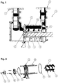
- Fig.1 shows as mentioned above a liquid ring pump solution 1 (motor not shown) according to the present invention. It includes a pump housing 2 and a helical screw rotor 4.
- the pump unit as such further includes an inlet part 3 with an inlet (inlet connection) 5.
- the screw rotor 4 with helically provided wings 16 is provided on a shaft 18 which may be an individual component or common for the motor and the pump.
- the rotor housing 2 is further connected to an outlet part or pressure chamber part 6 with an outlet (connection part) 7.
- the main parts of the pump unit 1, i.e. the inlet part 3, the rotor housing 2 and the outlet part 6 are provided with intermediate sealing elements 8, 9 (see Fig. 2 ) and are held together in a tight connection by means of suitable screws 10.
- the pump 1 further comprises a grinder 11 including a rotary cutter 12 attached to the outer end of the helical screw 4 shaft by means of a threaded screw 14 and a stationary part 13 attached to a grinder housing plate 15 by means of other suitable threaded screws 16.
- the rotary cutter 12 is freely rotating within the stationary cutter 13 and when the pump is running, liquid including any larger particles such as textiles etc. passes by the cutters, whereby the particles are ground (by the cutters) to fine pieces avoiding clogging and eventually stoppage of the pump.
- Figs. 3 and 4 respectively shows in larger scale the rotary cutter 12 and stationary cutter 13.
- the stationary cutter 13 is provided with inwardly (in relation to the helical screw) protruding fingers 17 with cutting edges or knifes with positive cutting angle edge19.
- the inventive feature of the rotating cutter 12 is the design of the cutting tools where each tool has cutting edges or knifes 20 provided on respective curved wings 21, which wings are shaped like the wings on a pump impeller.
- Each wing 21, as shown in Fig. 3 stretches from a front part of the cutter (inlet end relative to the pump) and ends in a flange or circular rear part 22 complimentary to a front part 24 (see Fig. 2 ) of the helical screw 4 on to which it is attached.
- the helical wings 21 of the rotary cutter 12 correspond to and have the same direction as the wings 16 of the helical screw rotor 4.
- the direction of grooves between the fingers 17 of stationary cutter 13 has the opposite direction.
- a knob or protrusion 23 stretching forward and beyond the wing cutter tools 21.
- the purpose of the protrusion 23 is to repel any compact pieces of metal or the like and thereby protect the grinder from being damaged.
- the rotary cutter 12 according to the present invention is not only shaped for grinding soft material but is as well designed to contribute to the pumping of the liquid through the macerator and thereby making the pump more efficient and effective.
- Tests were performed with a Jets' 95 MB pump comparing efficiency, capacity and grinding (cutting) ability for a pump with the old type of rotary cutter knives with the same pump but with the new type of rotary cutter knives according to the present invention.
- the two test pumps with the old and new macerator respectively were tested under the same conditions, i. e. with the same gas/liquid ratio and same operating conditions.
- a "particle" in the form of floor washing cloth or textile mop, 60 cm long was sucked into the pump and used as material for the grinding tests.
- the results of the grinding of the textile mop were investigated "manually", comparing by measuring the size of ground particles for each test, by visually comparing the outer appearance of the particles from each test and by inspection, by inspection of the interior of the pump and by measuring the time it took to macerate textile mop completely.
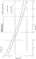
- FIG. 6 is a diagram showing the efficiency, Q/P, i. e. the fluid volume/effect vs. the degree (percentage) of vacuum.
- Fig. 7 shows the capacity Q, i.e. the fluid volume vs. the degree of vacuum for each of the pumps.
- Fig. 6 shows that the increase in Q/P relationship (fluid volume and effect relationship) vs. degree of vacuum varies between 10 % (at a vacuum of 10%) and 25% (at 60% vacuum).
- Fig. 7 the improvement of capacity, i.e. the pumped fluid volume vs. degree of vacuum varies between 8% (at 10% vacuum) and 15% (at 60% vacuum).
- the shape of the wings may, within the scope of the claims, vary depending among on the size of the pump and the angular velocity (RPM) for which the pump is designed.
- the wings 21 of the rotary cutter 12 may have a different length as well as curvature from what is shown in the drawings.
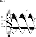
- the wings 21 of the cutter may correspond with the wings of the helical pump screw 4 thereby forming a continued screw design as indicated in Fig. 5 where arrows indicate the continued flow pattern of the combined cutter and helical screw rotor through the stationary and rotary cutter 13 resp. 12 and further along the pump screw 4.
Landscapes
- Engineering & Computer Science (AREA)
- Mechanical Engineering (AREA)
- General Engineering & Computer Science (AREA)
- Food Science & Technology (AREA)
- Environmental & Geological Engineering (AREA)
- Structures Of Non-Positive Displacement Pumps (AREA)
- Crushing And Pulverization Processes (AREA)
- Rotary Pumps (AREA)
- Disintegrating Or Milling (AREA)
Description
- The present invention relates to a screw type liquid ring pump with an integrated grinder or macerator, including a pump housing with an inlet and an outlet and an, inside the housing, rotating helical screw rotor, which rotor at one end, the inlet end of the pump housing is provided with the grinder an at the other end, the outlet end of the pump housing is connected to a shaft which may be commonly provided for the rotor as well as a driving unit in the form of a motor, preferably an electric motor.
- Liquid ring pumps with a grinder of the above kind are commonly known where the pump and the driving unit, usually an electric motor, are built together forming one unit. With such solution the production is simplified and the costs are reduced, mainly due to the fact that fewer constructional parts are required. These types of pumps are now the most used pumps in the market for the generation of vacuum and simultaneously grinding of the sewage in vacuum sewage systems.
- In the applicants own European patent No.
0 454 794 from which the features of the preamble ofclaim 1 are known, an example is shown of a conventional liquid ring type helical screw pump of the above-mentioned type driven by an electrical motor and being provided with an integrated macerator. The macerator includes a stationary part attached to the inlet end of the pump housing and a rotating part connected to the inlet end of the rotor shaft. Each of the stationary and rotating parts are provided with interacting cutting knives which are designed to cut larger pieces of material such as paper, fabric material or excrements to small pieces before entering the rotor and rotor housing of the pump. - This known type of macerator is very effective as regards macerating ability, but represents a hindrance for the flow of the sewage through the pump and thereby reduces the pumping efficiency of the pump.
-
WO 2006/058605 A1 discloses a pump having an axial impeller with helical blades for sucking liquid through an intake opening. - With the present invention is provided an improved macerator solution where the macerating ability and efficiency is maintained, but where the efficiency of the pump is vastly improved.
- The invention is characterized by the features as defined in the attached
independent claim 1. - Independent claims 2-3define preferred embodiments of the invention.
- The invention will be further described in the following with reference to the drawings in which:
-
Fig .1 shows a cross sectional view of a screw type liquid ring pump with integrated macerator according to the invention, -
Fig. 2 shows an expanded view of part of the pump shown inFig. 1 including the screw rotor, end lid and stationary and rotary part of the macerator, -
Fig. 3 shows in larger scale the rotary cutter of the macerator, and -
Fig. 4 shows the stationary part of the macerator as shown inFigs. 1 and 2 , -
Fig. 5 shows the combined rotary cutter and helical screw rotor design with an indication of the continued flow pattern of such design, -
Fig. 6 is diagram showing the pump efficiency of a pump with the old type of rotary cutter and with the rotary cutter according to the present invention, -
Fig. 7 is a diagram showing the capacity of a pump with the old type of rotary cutter and with the rotary cutter according to the present invention. -
Fig.1 shows as mentioned above a liquid ring pump solution 1 (motor not shown) according to the present invention. It includes apump housing 2 and ahelical screw rotor 4. The pump unit as such further includes aninlet part 3 with an inlet (inlet connection) 5. Thescrew rotor 4 with helically providedwings 16 is provided on ashaft 18 which may be an individual component or common for the motor and the pump. Therotor housing 2 is further connected to an outlet part orpressure chamber part 6 with an outlet (connection part) 7. - The main parts of the
pump unit 1, i.e. theinlet part 3, therotor housing 2 and theoutlet part 6 are provided withintermediate sealing elements 8, 9 (seeFig. 2 ) and are held together in a tight connection by means ofsuitable screws 10. - As seen in
Figs. 1 and 2 thepump 1 further comprises agrinder 11 including arotary cutter 12 attached to the outer end of thehelical screw 4 shaft by means of a threadedscrew 14 and astationary part 13 attached to agrinder housing plate 15 by means of other suitable threadedscrews 16. - The
rotary cutter 12 is freely rotating within thestationary cutter 13 and when the pump is running, liquid including any larger particles such as textiles etc. passes by the cutters, whereby the particles are ground (by the cutters) to fine pieces avoiding clogging and eventually stoppage of the pump. -
Figs. 3 and 4 respectively shows in larger scale therotary cutter 12 andstationary cutter 13. Thestationary cutter 13 is provided with inwardly (in relation to the helical screw) protrudingfingers 17 with cutting edges or knifes with positive cutting angle edge19. On the other hand, the inventive feature of the rotatingcutter 12 is the design of the cutting tools where each tool has cutting edges orknifes 20 provided on respectivecurved wings 21, which wings are shaped like the wings on a pump impeller. Eachwing 21, as shown inFig. 3 , stretches from a front part of the cutter (inlet end relative to the pump) and ends in a flange or circularrear part 22 complimentary to a front part 24 (seeFig. 2 ) of thehelical screw 4 on to which it is attached. Preferably thehelical wings 21 of therotary cutter 12 correspond to and have the same direction as thewings 16 of thehelical screw rotor 4. On the other hand the direction of grooves between thefingers 17 ofstationary cutter 13 has the opposite direction. - On the front part of one of the
wings 21 is in addition provided a knob orprotrusion 23 stretching forward and beyond thewing cutter tools 21. The purpose of theprotrusion 23 is to repel any compact pieces of metal or the like and thereby protect the grinder from being damaged. - Thus, with the above described novel design the
rotary cutter 12 according to the present invention is not only shaped for grinding soft material but is as well designed to contribute to the pumping of the liquid through the macerator and thereby making the pump more efficient and effective. - Tests were performed with a Jets' 95 MB pump comparing efficiency, capacity and grinding (cutting) ability for a pump with the old type of rotary cutter knives with the same pump but with the new type of rotary cutter knives according to the present invention.
- The two test pumps with the old and new macerator respectively were tested under the same conditions, i. e. with the same gas/liquid ratio and same operating conditions. Under each of the tests, a "particle" in the form of floor washing cloth or textile mop, 60 cm long was sucked into the pump and used as material for the grinding tests. The results of the grinding of the textile mop were investigated "manually", comparing by measuring the size of ground particles for each test, by visually comparing the outer appearance of the particles from each test and by inspection, by inspection of the interior of the pump and by measuring the time it took to macerate textile mop completely.
- Further, measurements were done to compare the capacity and efficiency of the pumps for the two tests.
Fig. 6 is a diagram showing the efficiency, Q/P, i. e. the fluid volume/effect vs. the degree (percentage) of vacuum.Fig. 7 shows the capacity Q, i.e. the fluid volume vs. the degree of vacuum for each of the pumps. - Visual inspection showed minor or no difference between the ground particles of the pump with the old cutter and old knives compared to the new cutter with its knives as the particle size as well as the outer appearance was basically the same. Demounting and visual inspection of the interior of each pump showed as well that there was no material particles left in the pumps, they were both completely empty. Further, the time it took to grind the textile mop for each of the pumps was approximately 90 seconds. Therefore the conclusion based on the manual inspection is that the grinding properties are the same for the new macerator as for the old macerator.
- As to efficiency and capacity, however, the new macerator shows vast improvements. Thus,
Fig. 6 shows that the increase in Q/P relationship (fluid volume and effect relationship) vs. degree of vacuum varies between 10 % (at a vacuum of 10%) and 25% (at 60% vacuum). Further, as is shown inFig. 7 the improvement of capacity, i.e. the pumped fluid volume vs. degree of vacuum varies between 8% (at 10% vacuum) and 15% (at 60% vacuum). - It should be noted, even though the example shown in the drawings and described above include
wings 21 with a particular curvature, length and visual design, the shape of the wings may, within the scope of the claims, vary depending among on the size of the pump and the angular velocity (RPM) for which the pump is designed. Thus, thewings 21 of therotary cutter 12 may have a different length as well as curvature from what is shown in the drawings. Further, thewings 21 of the cutter may correspond with the wings of thehelical pump screw 4 thereby forming a continued screw design as indicated inFig. 5 where arrows indicate the continued flow pattern of the combined cutter and helical screw rotor through the stationary androtary cutter 13 resp. 12 and further along thepump screw 4.
Claims (3)
- Screw type liquid ring pump (1) with an integrated grinder or macerator (11) including a pump housing (2) with an inlet (5) and an outlet (7) and a rotatable helical screw rotor (4) inside the pump housing (2), which helical screw rotor (4) at one end, the inlet end of the pump housing (2), is provided with the grinder or macerator (11) and at the other end, the outlet end of the pump housing (2), is communicating with a pressure chamber (6), the helical screw rotor (4) being provided on a shaft (18) connected to a driving unit in the form of a motor, preferably an electric motor,
wherein the grinder or macerator (11) includes a rotary cutter (12) attached to the inlet end of the helical screw rotor shaft (18) and a stationary cutter (13) attached to a housing part (15) of the grinder or macerator (11), wherein each of the rotary and stationary cutters (12, 13) are provided with cutting tools or knives (20, 19), wherein the rotary cutter (12) is freely rotating within the stationary cutter (13) when the pump is running, and wherein each cutting tool or knife (20) of the rotary cutter (12) has a cutting edge provided on a curved wing (21),
characterised in that the rotary cutter (12) is shaped like a pump impeller contributing to the pumping of the liquid through the grinder or macerator (11), and in that the stationary cutter (13) is provided with inwardly, in relation to the helical screw rotor (4), protruding fingers (7) with cutting edges with a positive cutting angle edge. - Screw pump according to claim 1, characterised in that the length and curvature of each wing (21) of the rotary cutter (12) varies depending on the pump size, capacity and angular velocity.
- Screw pump according to claim 1, characterised in that the curved wings (21) of the rotary cutter (12) correspond to and have the same direction as wings (16) of the helical screw rotor (4), whereas grooves between the fingers (17) of the stationary cutter (13) are directed in an opposite direction.
Priority Applications (2)
| Application Number | Priority Date | Filing Date | Title |
|---|---|---|---|
| HRP20171860TT HRP20171860T1 (en) | 2011-06-17 | 2012-06-12 | Screw type liquid ring pump with integrated macerator |
| PL12800220T PL2721299T3 (en) | 2011-06-17 | 2012-06-12 | Screw type liquid ring pump with integrated macerator |
Applications Claiming Priority (2)
| Application Number | Priority Date | Filing Date | Title |
|---|---|---|---|
| NO20110876 | 2011-06-17 | ||
| PCT/NO2012/000045 WO2012173488A1 (en) | 2011-06-17 | 2012-06-12 | Screw type liquid ring pump with integrated macerator |
Publications (3)
| Publication Number | Publication Date |
|---|---|
| EP2721299A1 EP2721299A1 (en) | 2014-04-23 |
| EP2721299A4 EP2721299A4 (en) | 2015-02-25 |
| EP2721299B1 true EP2721299B1 (en) | 2017-08-30 |
Family
ID=47357303
Family Applications (1)
| Application Number | Title | Priority Date | Filing Date |
|---|---|---|---|
| EP12800220.1A Active EP2721299B1 (en) | 2011-06-17 | 2012-06-12 | Screw type liquid ring pump with integrated macerator |
Country Status (11)
| Country | Link |
|---|---|
| US (1) | US9097257B2 (en) |
| EP (1) | EP2721299B1 (en) |
| CN (1) | CN103890402B (en) |
| CY (1) | CY1119630T1 (en) |
| DK (1) | DK2721299T3 (en) |
| ES (1) | ES2648162T3 (en) |
| HR (1) | HRP20171860T1 (en) |
| NO (1) | NO2721299T3 (en) |
| PL (1) | PL2721299T3 (en) |
| RU (1) | RU2602712C2 (en) |
| WO (1) | WO2012173488A1 (en) |
Families Citing this family (8)
| Publication number | Priority date | Publication date | Assignee | Title |
|---|---|---|---|---|
| US10030654B2 (en) * | 2013-05-16 | 2018-07-24 | Jets As | Liquid ring screw pump functional design |
| CN104533844B (en) * | 2014-12-25 | 2017-12-01 | 东营国安化工有限公司 | The dredge pump and medium separation method of a kind of sewage pump medium separation hood and its composition |
| US11338476B2 (en) * | 2018-12-07 | 2022-05-24 | Nilo Global Limited | Plastic processing apparatus and related methods |
| RU188713U1 (en) * | 2018-12-21 | 2019-04-22 | Общество с ограниченной ответственностью "КДС" | Liquid ring pump |
| LU102842B1 (en) * | 2021-06-24 | 2022-12-29 | Wilo Se | cutting head of a pump |
| LU102840B1 (en) * | 2021-06-24 | 2022-12-27 | Wilo Se | Cutting ring for a pump liquid loaded with solids |
| CN114319551A (en) * | 2021-11-30 | 2022-04-12 | 安徽扬基环保科技有限公司 | Integral type automatically regulated rainwater vatch basin |
| US12083527B2 (en) | 2022-10-04 | 2024-09-10 | Wilo Se | Cutting ring for a pump liquid loaded with solids |
Family Cites Families (14)
| Publication number | Priority date | Publication date | Assignee | Title |
|---|---|---|---|---|
| US2029766A (en) * | 1934-08-18 | 1936-02-04 | Chicago Pump Co | Screw feed centrifugal pump |
| US2658453A (en) * | 1950-07-22 | 1953-11-10 | Pacific Pumps Inc | Nonclogging pumping device |
| US3643877A (en) * | 1970-01-28 | 1972-02-22 | Robbins & Myers | Pump with macerator |
| US4141510A (en) * | 1977-06-15 | 1979-02-27 | Arthur Smith | Material reduction means for pumps |
| SE459877B (en) * | 1983-09-16 | 1989-08-14 | Hans Baeckstroem | DEVICE FOR THE TRANSPORT OF PAST PROTECTIVE DRUGS WITH THE PUMP PROTECTOR OF A ROTATING DEPLACEMENT TYPE |
| NO167931B (en) * | 1989-03-03 | 1991-09-16 | Jets Systemer As | VACUUM DRAINAGE SYSTEM |
| US5016825A (en) * | 1990-02-14 | 1991-05-21 | Mcneil (Ohio) Corporation | Grinding impeller assembly for a grinder pump |
| US5302082A (en) * | 1992-07-09 | 1994-04-12 | Arde, Inc. | Improved efficiency grinding pump for slurry |
| US20040234370A1 (en) * | 2002-09-26 | 2004-11-25 | Mark Simakaski | Chopping pump impeller assembly |
| NO318776B1 (en) * | 2003-05-07 | 2005-05-02 | Jets As | Screw-type liquid pump pump device |
| BRPI0518771B1 (en) * | 2004-12-03 | 2018-05-22 | Brinkmann Pumpen K.H. Brinkmann Gmbh & Co. Kg | PUMP HAVING AXIAL IMPULSOR WITH HELICAL BLADES AND METHOD FOR PUMPING COOLING AND LUBRICATION LIQUIDS |
| DE102004058458B3 (en) * | 2004-12-03 | 2006-05-18 | Brinkmann Pumpen K.H. Brinkmann Gmbh & Co. Kg | Pump with axial impeller e.g. for pump, has screw-shaped wings for sucking in liquid by inlet port arranged at lower surface of axial impeller with wings at lower surface have cutting edge |
| CN100404874C (en) | 2006-01-21 | 2008-07-23 | 阳江市新力工业有限公司 | A kind of stamping and welding food pump |
| CN101544460B (en) * | 2009-04-30 | 2011-06-15 | 深圳市新环机械工程设备有限公司 | Sludge cutting machine |
-
2012
- 2012-06-12 EP EP12800220.1A patent/EP2721299B1/en active Active
- 2012-06-12 PL PL12800220T patent/PL2721299T3/en unknown
- 2012-06-12 US US14/125,999 patent/US9097257B2/en active Active
- 2012-06-12 DK DK12800220.1T patent/DK2721299T3/en active
- 2012-06-12 ES ES12800220.1T patent/ES2648162T3/en active Active
- 2012-06-12 RU RU2013158608/06A patent/RU2602712C2/en active
- 2012-06-12 HR HRP20171860TT patent/HRP20171860T1/en unknown
- 2012-06-12 WO PCT/NO2012/000045 patent/WO2012173488A1/en not_active Ceased
- 2012-06-12 CN CN201280029908.4A patent/CN103890402B/en active Active
- 2012-06-12 NO NO12800220A patent/NO2721299T3/no unknown
-
2017
- 2017-11-27 CY CY20171101245T patent/CY1119630T1/en unknown
Non-Patent Citations (1)
| Title |
|---|
| None * |
Also Published As
| Publication number | Publication date |
|---|---|
| US9097257B2 (en) | 2015-08-04 |
| CN103890402B (en) | 2017-02-15 |
| DK2721299T3 (en) | 2017-12-11 |
| EP2721299A4 (en) | 2015-02-25 |
| NO2721299T3 (en) | 2018-01-27 |
| RU2602712C2 (en) | 2016-11-20 |
| ES2648162T3 (en) | 2017-12-28 |
| RU2013158608A (en) | 2015-07-27 |
| CY1119630T1 (en) | 2018-04-04 |
| CN103890402A (en) | 2014-06-25 |
| PL2721299T3 (en) | 2018-02-28 |
| HRP20171860T1 (en) | 2018-01-26 |
| EP2721299A1 (en) | 2014-04-23 |
| US20140119975A1 (en) | 2014-05-01 |
| WO2012173488A1 (en) | 2012-12-20 |
Similar Documents
| Publication | Publication Date | Title |
|---|---|---|
| US9097257B2 (en) | Screw type liquid ring pump with integrated macerator | |
| US7159806B1 (en) | Cutter assembly for a grinder pump | |
| JP6125794B2 (en) | Cutter assembly and high capacity submersible shredder pump | |
| KR100918876B1 (en) | Water grinder pump | |
| KR101775481B1 (en) | Filter Mechanism | |
| KR101562027B1 (en) | Underwater grinder pump | |
| JPS6354151B2 (en) | ||
| JP7193424B2 (en) | Cutter assembly and high capacity submersible shredder pump | |
| PL189274B1 (en) | Pump in particular for pumping polluted water | |
| US7510368B2 (en) | Screw-centrifugal pump | |
| KR102597700B1 (en) | A pump with cutting structure | |
| KR100722507B1 (en) | Submersible pump with foreign material cutting device | |
| EP0156845B1 (en) | Means for the handling of contaminated fluids | |
| CN201526460U (en) | Shear type sewage pump | |
| JP2008520889A (en) | Impeller wheel | |
| KR102597699B1 (en) | A pump with cutting structure | |
| US3120353A (en) | Rotary slurry pump | |
| CN209959474U (en) | Cutting type centrifugal submersible sewage pump | |
| CN208831253U (en) | A kind of sewage cutting pump | |
| KR102690588B1 (en) | A pump with cutting structure | |
| CN217974626U (en) | Kitchen garbage processor | |
| KR100508944B1 (en) | Sludge pump that is used to general | |
| KR102635073B1 (en) | A pump with cutting structure | |
| PL176596B1 (en) | Comminutig system for submersible pumps | |
| CN119801920A (en) | An environmentally friendly anti-clogging cam rotor pump with a chopping device |
Legal Events
| Date | Code | Title | Description |
|---|---|---|---|
| PUAI | Public reference made under article 153(3) epc to a published international application that has entered the european phase |
Free format text: ORIGINAL CODE: 0009012 |
|
| 17P | Request for examination filed |
Effective date: 20131216 |
|
| AK | Designated contracting states |
Kind code of ref document: A1 Designated state(s): AL AT BE BG CH CY CZ DE DK EE ES FI FR GB GR HR HU IE IS IT LI LT LU LV MC MK MT NL NO PL PT RO RS SE SI SK SM TR |
|
| RIN1 | Information on inventor provided before grant (corrected) |
Inventor name: OEVSTHUS, EIMUND Inventor name: OEVSTHUS, AKSEL |
|
| DAX | Request for extension of the european patent (deleted) | ||
| A4 | Supplementary search report drawn up and despatched |
Effective date: 20150126 |
|
| RIC1 | Information provided on ipc code assigned before grant |
Ipc: B02C 19/22 20060101ALI20150120BHEP Ipc: F04C 15/06 20060101ALI20150120BHEP Ipc: F04C 7/00 20060101AFI20150120BHEP Ipc: B02C 18/00 20060101ALI20150120BHEP Ipc: E03F 1/00 20060101ALI20150120BHEP |
|
| 17Q | First examination report despatched |
Effective date: 20160816 |
|
| STAA | Information on the status of an ep patent application or granted ep patent |
Free format text: STATUS: EXAMINATION IS IN PROGRESS |
|
| GRAP | Despatch of communication of intention to grant a patent |
Free format text: ORIGINAL CODE: EPIDOSNIGR1 |
|
| STAA | Information on the status of an ep patent application or granted ep patent |
Free format text: STATUS: GRANT OF PATENT IS INTENDED |
|
| INTG | Intention to grant announced |
Effective date: 20170406 |
|
| GRAS | Grant fee paid |
Free format text: ORIGINAL CODE: EPIDOSNIGR3 |
|
| GRAA | (expected) grant |
Free format text: ORIGINAL CODE: 0009210 |
|
| STAA | Information on the status of an ep patent application or granted ep patent |
Free format text: STATUS: THE PATENT HAS BEEN GRANTED |
|
| AK | Designated contracting states |
Kind code of ref document: B1 Designated state(s): AL AT BE BG CH CY CZ DE DK EE ES FI FR GB GR HR HU IE IS IT LI LT LU LV MC MK MT NL NO PL PT RO RS SE SI SK SM TR |
|
| REG | Reference to a national code |
Ref country code: GB Ref legal event code: FG4D |
|
| REG | Reference to a national code |
Ref country code: CH Ref legal event code: EP |
|
| REG | Reference to a national code |
Ref country code: AT Ref legal event code: REF Ref document number: 923829 Country of ref document: AT Kind code of ref document: T Effective date: 20170915 |
|
| REG | Reference to a national code |
Ref country code: IE Ref legal event code: FG4D |
|
| REG | Reference to a national code |
Ref country code: DE Ref legal event code: R096 Ref document number: 602012036696 Country of ref document: DE |
|
| REG | Reference to a national code |
Ref country code: SE Ref legal event code: TRGR |
|
| REG | Reference to a national code |
Ref country code: HR Ref legal event code: TUEP Ref document number: P20171860 Country of ref document: HR |
|
| REG | Reference to a national code |
Ref country code: CH Ref legal event code: NV Representative=s name: FELBER UND PARTNER AG, CH |
|
| REG | Reference to a national code |
Ref country code: NL Ref legal event code: FP |
|
| REG | Reference to a national code |
Ref country code: DK Ref legal event code: T3 Effective date: 20171206 |
|
| REG | Reference to a national code |
Ref country code: ES Ref legal event code: FG2A Ref document number: 2648162 Country of ref document: ES Kind code of ref document: T3 Effective date: 20171228 |
|
| REG | Reference to a national code |
Ref country code: LT Ref legal event code: MG4D |
|
| REG | Reference to a national code |
Ref country code: HR Ref legal event code: T1PR Ref document number: P20171860 Country of ref document: HR |
|
| PG25 | Lapsed in a contracting state [announced via postgrant information from national office to epo] |
Ref country code: LT Free format text: LAPSE BECAUSE OF FAILURE TO SUBMIT A TRANSLATION OF THE DESCRIPTION OR TO PAY THE FEE WITHIN THE PRESCRIBED TIME-LIMIT Effective date: 20170830 |
|
| REG | Reference to a national code |
Ref country code: NO Ref legal event code: T2 Effective date: 20170830 |
|
| PG25 | Lapsed in a contracting state [announced via postgrant information from national office to epo] |
Ref country code: RS Free format text: LAPSE BECAUSE OF FAILURE TO SUBMIT A TRANSLATION OF THE DESCRIPTION OR TO PAY THE FEE WITHIN THE PRESCRIBED TIME-LIMIT Effective date: 20170830 Ref country code: BG Free format text: LAPSE BECAUSE OF FAILURE TO SUBMIT A TRANSLATION OF THE DESCRIPTION OR TO PAY THE FEE WITHIN THE PRESCRIBED TIME-LIMIT Effective date: 20171130 Ref country code: LV Free format text: LAPSE BECAUSE OF FAILURE TO SUBMIT A TRANSLATION OF THE DESCRIPTION OR TO PAY THE FEE WITHIN THE PRESCRIBED TIME-LIMIT Effective date: 20170830 Ref country code: IS Free format text: LAPSE BECAUSE OF FAILURE TO SUBMIT A TRANSLATION OF THE DESCRIPTION OR TO PAY THE FEE WITHIN THE PRESCRIBED TIME-LIMIT Effective date: 20171230 |
|
| PG25 | Lapsed in a contracting state [announced via postgrant information from national office to epo] |
Ref country code: CZ Free format text: LAPSE BECAUSE OF FAILURE TO SUBMIT A TRANSLATION OF THE DESCRIPTION OR TO PAY THE FEE WITHIN THE PRESCRIBED TIME-LIMIT Effective date: 20170830 Ref country code: RO Free format text: LAPSE BECAUSE OF FAILURE TO SUBMIT A TRANSLATION OF THE DESCRIPTION OR TO PAY THE FEE WITHIN THE PRESCRIBED TIME-LIMIT Effective date: 20170830 |
|
| REG | Reference to a national code |
Ref country code: GR Ref legal event code: EP Ref document number: 20170403264 Country of ref document: GR Effective date: 20180420 |
|
| PG25 | Lapsed in a contracting state [announced via postgrant information from national office to epo] |
Ref country code: SK Free format text: LAPSE BECAUSE OF FAILURE TO SUBMIT A TRANSLATION OF THE DESCRIPTION OR TO PAY THE FEE WITHIN THE PRESCRIBED TIME-LIMIT Effective date: 20170830 Ref country code: SM Free format text: LAPSE BECAUSE OF FAILURE TO SUBMIT A TRANSLATION OF THE DESCRIPTION OR TO PAY THE FEE WITHIN THE PRESCRIBED TIME-LIMIT Effective date: 20170830 Ref country code: EE Free format text: LAPSE BECAUSE OF FAILURE TO SUBMIT A TRANSLATION OF THE DESCRIPTION OR TO PAY THE FEE WITHIN THE PRESCRIBED TIME-LIMIT Effective date: 20170830 |
|
| REG | Reference to a national code |
Ref country code: DE Ref legal event code: R097 Ref document number: 602012036696 Country of ref document: DE |
|
| REG | Reference to a national code |
Ref country code: FR Ref legal event code: PLFP Year of fee payment: 7 |
|
| PLBE | No opposition filed within time limit |
Free format text: ORIGINAL CODE: 0009261 |
|
| STAA | Information on the status of an ep patent application or granted ep patent |
Free format text: STATUS: NO OPPOSITION FILED WITHIN TIME LIMIT |
|
| 26N | No opposition filed |
Effective date: 20180531 |
|
| PG25 | Lapsed in a contracting state [announced via postgrant information from national office to epo] |
Ref country code: SI Free format text: LAPSE BECAUSE OF FAILURE TO SUBMIT A TRANSLATION OF THE DESCRIPTION OR TO PAY THE FEE WITHIN THE PRESCRIBED TIME-LIMIT Effective date: 20170830 |
|
| REG | Reference to a national code |
Ref country code: BE Ref legal event code: MM Effective date: 20180630 |
|
| REG | Reference to a national code |
Ref country code: IE Ref legal event code: MM4A |
|
| PG25 | Lapsed in a contracting state [announced via postgrant information from national office to epo] |
Ref country code: LU Free format text: LAPSE BECAUSE OF NON-PAYMENT OF DUE FEES Effective date: 20180612 Ref country code: MC Free format text: LAPSE BECAUSE OF FAILURE TO SUBMIT A TRANSLATION OF THE DESCRIPTION OR TO PAY THE FEE WITHIN THE PRESCRIBED TIME-LIMIT Effective date: 20170830 |
|
| PG25 | Lapsed in a contracting state [announced via postgrant information from national office to epo] |
Ref country code: IE Free format text: LAPSE BECAUSE OF NON-PAYMENT OF DUE FEES Effective date: 20180612 |
|
| PG25 | Lapsed in a contracting state [announced via postgrant information from national office to epo] |
Ref country code: BE Free format text: LAPSE BECAUSE OF NON-PAYMENT OF DUE FEES Effective date: 20180630 |
|
| REG | Reference to a national code |
Ref country code: HR Ref legal event code: ODRP Ref document number: P20171860 Country of ref document: HR Payment date: 20190530 Year of fee payment: 8 |
|
| PG25 | Lapsed in a contracting state [announced via postgrant information from national office to epo] |
Ref country code: MT Free format text: LAPSE BECAUSE OF NON-PAYMENT OF DUE FEES Effective date: 20180612 |
|
| REG | Reference to a national code |
Ref country code: DE Ref legal event code: R082 Ref document number: 602012036696 Country of ref document: DE Ref country code: DE Ref legal event code: R082 Ref document number: 602012036696 Country of ref document: DE Representative=s name: MAIWALD GMBH, DE Ref country code: DE Ref legal event code: R082 Ref document number: 602012036696 Country of ref document: DE Representative=s name: MAIWALD PATENTANWALTS- UND RECHTSANWALTSGESELL, DE |
|
| REG | Reference to a national code |
Ref country code: DE Ref legal event code: R082 Ref document number: 602012036696 Country of ref document: DE Representative=s name: MAIWALD GMBH, DE Ref country code: DE Ref legal event code: R082 Ref document number: 602012036696 Country of ref document: DE Representative=s name: MAIWALD PATENTANWALTS- UND RECHTSANWALTSGESELL, DE |
|
| REG | Reference to a national code |
Ref country code: NO Ref legal event code: CHAD Owner name: JETS AS, NO Ref country code: NO Ref legal event code: CREP Representative=s name: BRYN AARFLOT AS, STORTINGSGATA 8, 0161 OSLO, NORGE |
|
| PG25 | Lapsed in a contracting state [announced via postgrant information from national office to epo] |
Ref country code: HU Free format text: LAPSE BECAUSE OF FAILURE TO SUBMIT A TRANSLATION OF THE DESCRIPTION OR TO PAY THE FEE WITHIN THE PRESCRIBED TIME-LIMIT; INVALID AB INITIO Effective date: 20120612 Ref country code: PT Free format text: LAPSE BECAUSE OF FAILURE TO SUBMIT A TRANSLATION OF THE DESCRIPTION OR TO PAY THE FEE WITHIN THE PRESCRIBED TIME-LIMIT Effective date: 20170830 |
|
| REG | Reference to a national code |
Ref country code: HR Ref legal event code: ODRP Ref document number: P20171860 Country of ref document: HR Payment date: 20200608 Year of fee payment: 9 |
|
| PG25 | Lapsed in a contracting state [announced via postgrant information from national office to epo] |
Ref country code: MK Free format text: LAPSE BECAUSE OF NON-PAYMENT OF DUE FEES Effective date: 20170830 |
|
| PG25 | Lapsed in a contracting state [announced via postgrant information from national office to epo] |
Ref country code: AL Free format text: LAPSE BECAUSE OF FAILURE TO SUBMIT A TRANSLATION OF THE DESCRIPTION OR TO PAY THE FEE WITHIN THE PRESCRIBED TIME-LIMIT Effective date: 20170830 |
|
| REG | Reference to a national code |
Ref country code: HR Ref legal event code: ODRP Ref document number: P20171860 Country of ref document: HR Payment date: 20210608 Year of fee payment: 10 |
|
| REG | Reference to a national code |
Ref country code: AT Ref legal event code: UEP Ref document number: 923829 Country of ref document: AT Kind code of ref document: T Effective date: 20170830 |
|
| REG | Reference to a national code |
Ref country code: HR Ref legal event code: ODRP Ref document number: P20171860 Country of ref document: HR Payment date: 20220608 Year of fee payment: 11 |
|
| REG | Reference to a national code |
Ref country code: HR Ref legal event code: ODRP Ref document number: P20171860 Country of ref document: HR Payment date: 20230607 Year of fee payment: 12 |
|
| P01 | Opt-out of the competence of the unified patent court (upc) registered |
Effective date: 20230524 |
|
| REG | Reference to a national code |
Ref country code: HR Ref legal event code: ODRP Ref document number: P20171860 Country of ref document: HR Payment date: 20240521 Year of fee payment: 13 |
|
| REG | Reference to a national code |
Ref country code: HR Ref legal event code: ODRP Ref document number: P20171860 Country of ref document: HR Payment date: 20250514 Year of fee payment: 14 |
|
| PGFP | Annual fee paid to national office [announced via postgrant information from national office to epo] |
Ref country code: FI Payment date: 20250616 Year of fee payment: 14 |
|
| PGFP | Annual fee paid to national office [announced via postgrant information from national office to epo] |
Ref country code: PL Payment date: 20250514 Year of fee payment: 14 Ref country code: DE Payment date: 20250618 Year of fee payment: 14 |
|
| PGFP | Annual fee paid to national office [announced via postgrant information from national office to epo] |
Ref country code: GB Payment date: 20250618 Year of fee payment: 14 Ref country code: DK Payment date: 20250618 Year of fee payment: 14 |
|
| PGFP | Annual fee paid to national office [announced via postgrant information from national office to epo] |
Ref country code: NO Payment date: 20250618 Year of fee payment: 14 |
|
| PGFP | Annual fee paid to national office [announced via postgrant information from national office to epo] |
Ref country code: NL Payment date: 20250618 Year of fee payment: 14 |
|
| PGFP | Annual fee paid to national office [announced via postgrant information from national office to epo] |
Ref country code: HR Payment date: 20250514 Year of fee payment: 14 |
|
| PGFP | Annual fee paid to national office [announced via postgrant information from national office to epo] |
Ref country code: FR Payment date: 20250617 Year of fee payment: 14 |
|
| PGFP | Annual fee paid to national office [announced via postgrant information from national office to epo] |
Ref country code: GR Payment date: 20250619 Year of fee payment: 14 |
|
| PGFP | Annual fee paid to national office [announced via postgrant information from national office to epo] |
Ref country code: AT Payment date: 20250618 Year of fee payment: 14 |
|
| PGFP | Annual fee paid to national office [announced via postgrant information from national office to epo] |
Ref country code: TR Payment date: 20250523 Year of fee payment: 14 |
|
| PGFP | Annual fee paid to national office [announced via postgrant information from national office to epo] |
Ref country code: SE Payment date: 20250618 Year of fee payment: 14 |
|
| PGFP | Annual fee paid to national office [announced via postgrant information from national office to epo] |
Ref country code: ES Payment date: 20250710 Year of fee payment: 14 |
|
| PGFP | Annual fee paid to national office [announced via postgrant information from national office to epo] |
Ref country code: IT Payment date: 20250618 Year of fee payment: 14 |
|
| PGFP | Annual fee paid to national office [announced via postgrant information from national office to epo] |
Ref country code: CH Payment date: 20250701 Year of fee payment: 14 |
|
| PGFP | Annual fee paid to national office [announced via postgrant information from national office to epo] |
Ref country code: CY Payment date: 20250521 Year of fee payment: 14 |